
 Open Access Article
 This Open Access Article is licensed under a Creative Commons Attribution-Non Commercial 3.0 Unported Licence
Achieving strength and toughness limits of anisotropic microstructured alumina ceramics through interface engineering
Zezhou
He
 a,
Rohit Pratyush
Behera
a,
Huajian
Gao
*b and
Hortense
Le Ferrand
*ac
a,
Rohit Pratyush
Behera
a,
Huajian
Gao
*b and
Hortense
Le Ferrand
*ac
aSchool of Mechanical and Aerospace Engineering, Nanyang Technological University, 50 Nanyang avenue, 639798, Singapore. E-mail: hortense@ntu.edu.sg
bMechano-X Institute, Applied Mechanics Laboratory, Department of Engineering Mechanics, Tsinghua University, Beijing 100084, China. E-mail: gao.huajian@tsinghua.edu.cn
cSchool of Materials Science and Engineering, Nanyang Technological University, 50 Nanyang avenue, 639798, Singapore
First published on 4th December 2025
Abstract
Advanced ceramic composites face a critical challenge: achieving the combined strength and toughness as in natural materials like nacre. Bioinspired anisotropic microstructured ceramics (AMCs) address this by mimicking nacre's hierarchical architecture. However, the critical role of the ceramic–matrix interface is often overlooked, due to a fundamental conflict: the weak interfaces needed for toughening through crack deflection are naturally difficult to achieve with conventional sintering processes that prioritize densification. Here, we bridge this gap by establishing universal energy- and strength-governed criteria for crack deflection in staggered microstructures, revealing two key mechanisms to unlock the full potential of AMCs. First, a low-stiffness matrix redistributes stress to mitigate stress concentrations, thereby enhancing failure strength. Simultaneously, a low-toughness interface facilitates crack deflection, leading to crack branching, microplatelet bridging, and unstable crack growth. These mechanisms collectively amplify fracture toughness by enabling plastic-like deformation in brittle ceramics. In alumina AMCs, microplatelet thickness and interfacial toughness are identified as the primary factors reconciling experimental-theoretical discrepancies. By reducing microplatelet thickness to 300 nm and incorporating a compliant matrix, we predict a theoretical strength of 2.25 GPa. Critically, the matrix must strike a delicate balance: it must be weak enough to deflect cracks yet cohesive enough to operate near the crack-deflection threshold, thereby maximizing energy dissipation. Through systematic optimization of these parameters, we predict a 13.1- to 21.8-fold amplification in toughness for alumina AMCs. This performance surpasses most engineered ceramics and approaches the remarkable properties of nacre. By defining the precise interfacial properties required for optimal performance, our work provides clear screening criteria for mitigating the historical processing conflict, thereby establishing interface engineering as a cornerstone for designing next-generation ceramic composites capable of withstanding extreme environments.
New conceptsNacre-like all-ceramic metamaterials can be programmed by two interface descriptors: the stiffness ratio and the toughness/strength ratio between matrix and platelet. Adjusting these descriptors switches the dominant crack path (deflection versus penetration) and, in turn, the macroscopic crack-growth resistance. A compact design map, built from unit-cell analysis and discrete-element simulations, yields simple rules that are independent of platelet aspect ratio and transferable across different brittle ceramics. In this picture, interfacial properties redistribute stress and activate extrinsic dissipation through crack branching, bridging, and interlayer sliding, leading to plastic-like deformation in otherwise brittle ceramics. The framework shows how modest improvements in initiation toughness at the unit-cell scale can accumulate into large, size-dependent toughness amplification as the crack spans many repeats, and it identifies practical levers for fabrication, including matrix selection and platelet thickness, for heat-resistant, architected nacre-like ceramics. |
1. Introduction
Nacre-like composites with a brick-and-mortar hierarchical microstructure have attracted significant attention in recent years for their ability to combine exceptional strength and fracture toughness. Nacre, a nanocomposite composed of ∼95% brittle minerals and ∼5% ductile proteins arranged in a brick-and-mortar structure (Fig. 1a), achieves a fracture toughness of ∼10 MPa m0.5 (≈40 times higher than pure aragonite), while maintaining a strength of ∼140 MPa (versus ∼200 MPa for pure aragonite).1–3 This performance arises from the protein-based “mortar”, which redistributes stress, deflects cracks, and imparts damage tolerance to the brittle mineral phase.4–8 To replicate these properties, researchers have developed synthetic analogues using polymer or metallic mortars, such as polymethylmethacrylate (PMMA) mortar between alumina bricks,9 ethylene-vinyl acetate layers in glass bricks,10 and copper interlayers in alumina.11,12 However, these composites can degrade under extreme conditions, such as high temperature or oxidative environments, and often exhibit only moderate strength and fracture toughness. For instance, nacre-like composites with alumina bricks and polymer or metal mortar typically show strengths below 400 MPa and fracture toughness ≤10 MPa m0.5. This is far lower than the 600 MPa strength and 17.3 MPa m0.5 fracture toughness achieved by all-ceramic counterparts.13,14 Compared with polymer- and metal-based nacre-like composites, all-ceramic composites also offer greater resistance to environmental degradation, since oxide–oxide interfaces formed during sintering are far less sensitive to humidity and corrosion. Taken together, prior studies show that all-ceramic nacre-like composites can achieve high performance; however, delivering robust, environment-resistant operation with simultaneously high strength and high fracture toughness, particularly under severe thermal or oxidative conditions, remains unresolved. Here we adopt an interface-engineering design strategy in all-ceramic nacre-like composites: by tuning the ceramic–ceramic interface to control load transfer and crack-path selection, we aim to retain strength while increasing fracture toughness in a manner suitable for demanding environments. | ||
| Fig. 1 Microstructure and property benchmarks for nacre and nacre-like alumina. Representative microstructures of (a) natural nacre14 (electron micrograph; reproduced with permission from ref. 14; Copyright 2014, Springer Nature) and (b) nacre-like alumina (electron micrograph; this work). (c) Natural nacre demonstrates fracture toughness approximately 40 times higher than that of its mineral bricks, while its strength approaches the yield stress of the mineral bricks under uniform loading.3,7 (d) The specific strength and toughness of nacre-like alumina are still limited by an insufficient understanding of the roles of nacre microstructure and interfacial properties.9,14–17 Source data and digitized values used for panels (c) and (d) are provided in the SI in Table S1. Panel (a) reproduced with permission from ref. 14. The “specific” values denote normalization by density ρ: specific strength = σ/ρ and specific fracture toughness KIc/ρ; densities are expressed in g mL−1 (where 1 g mL−1 = 1000 kg m−3). | ||
Previous studies on all-ceramic nacre-like microstructures, or anisotropic microstructured ceramics (AMCs), in which ceramic microplatelets (“bricks”) are embedded in a ceramic matrix (“mortar”) (Fig. 1b), have reported high strength, elevated fracture toughness,14,15,18,19 and good high-temperature performance.13,19 These gains are commonly attributed to ceramic constituents and architecture-induced anisotropy, which promote microplatelet bridging and crack deflection.13 Yet, the realized fracture toughness gains in AMCs remain below bioinspired benchmarks. For example, the toughness amplification factor (TAF), defined as the ratio of AMC fracture toughness to that of its primary ceramic (KJc,AMC/KIc,brick), rarely exceeds 10 and often remains ∼5, while natural nacre achieves up to 40 (Fig. 1c).3,6,13 Although AMCs exhibit enhanced fracture toughness, their failure strength is significantly compromised due to the inherent strength–toughness trade-off. Fig. 1(d) shows that AMC failure strength may decline by up to 50% relative to alumina microplatelets, whereas natural nacre shows only a ∼30% decrease.9,14–17 This gap motivates interface-focused design and modeling to guide experiments toward more balanced strength–fracture–toughness performance (Fig. 1c).
Resolving the strength–toughness trade-off in nacre-like composites requires optimizing both microstructural geometry and ceramic–ceramic interfacial properties. In all-ceramic architectures, however, this goal is particularly challenging. Fracture surface observations reveal that ceramic microplatelets with large aspect ratios often fail by tensile fracture rather than interfacial sliding during crack propagation,5,8,11,12,20 thereby suppressing extrinsic toughening mechanisms such as crack bridging and lowering the TAF.4,21,22 This limitation can be addressed by balancing component properties. For instance, molecular mechanics simulations suggest that balancing matrix and brick stiffness, with a matrix-to-brick stiffness ratio of 0.3–0.6, can preserve structural rigidity while avoiding brittle failure.23 Additionally, a systematic optimization strategy for staggered composites has been proposed, offering guidelines for platelet dimensions, material properties, volume content, interface strength, and platelet overlap.7,24–26
The primary constraint to implementing these theoretical designs is processing. Historically, introducing weak interfaces to promote crack deflection increases apparent toughness, but conventional densification and sintering make such interfaces difficult to reproduce. This conflict between “interfaces that toughen” and “processes that densify” was recognized early and remains a practical constraint for modern all-ceramic systems.27 Consequently, many advances primarily apply to nacre-like composites with ductile polymer or metal matrices,28–30 leaving all-ceramic AMCs comparatively underexplored. Predictive, fabrication-aware models for their mechanical behavior remain limited,23,31–33 and high-temperature fabrication further complicates microstructure control through grain growth and diffusion, creating coupled constraints across material selection, processing, and architecture.11,13,18 To bridge fabrication and modeling, we employ interface engineering, defined within a mechanics-guided design framework that focuses on tuning effective interfacial stiffness and toughness at the mesoscale rather than prescribing a specific experimentally realized interface chemistry. This design framework selects a ceramic matrix and processing conditions to achieve interfacial properties that guide crack propagation while maintaining overall strength. This approach focuses on a small set of controllable parameters: platelet thickness, matrix layer thickness, and interfacial toughness and stiffness.34,35 A central question for all-ceramic AMCs is therefore: which matrix/interfacial combinations best reconcile deflection-driven toughening with strength retention under realistic sintering windows?
Here, we advance an interface-engineering design framework for AMCs viewed as mechanical metamaterials, in which the macroscopic fracture response is governed by the architected microstructure rather than by the homogeneous properties of the base ceramics. We posit that ceramic–ceramic interfaces, rather than platelet aspect ratio alone, govern crack-path selection and thus the attainable balance of strength and fracture toughness. First (Section 2), we formulate minimal both energy- and strength-based criteria for interface-guided crack deflection in staggered architectures and evaluate them with a simplified unit-cell model. Second (Section 3.1), we test these criteria using discrete-element simulations at the unit-cell level and identify a performance ridge near the deflection–penetration boundary that maximizes energy dissipation. Third (Sections 3.2 and 3.3), we track full-field crack evolution and rising R-curve behavior and then translate the design rules to alumina systems, identifying microplatelet thickness and interfacial toughness as actionable experimental levers. Fourth (Section 3.4), we discuss processing-aware guidance for matrix selection and interface control. Finally (Section 4), we summarize the implications for programmable, nacre-like metamaterials, where interface tuning directly programs the crack path and the rising resistance curve and thereby enables damage-tolerant responses in all-ceramic architectures.
2. Theoretical considerations
This section introduces the minimal unit-cell framework and notation, and derives the interface-engineered criteria used to predict whether a crack deflects or penetrates. Interface engineering here means selecting the matrix properties so that the interfacial stiffness, strength, and toughness can steer cracks along platelet–matrix interfaces, where deflection, sliding, and bridging can occur. The overall architecture, unit cell, and representative failure modes are summarized in Fig. 2. | ||
| Fig. 2 Structural model of bioinspired AMCs. (a) Schematic representation of staggered ceramic microplatelets embedded in a ceramic matrix. (b) Simplified load-transfer unit cell: the ceramic microplatelet carries most of the axial load, while the ceramic matrix transfers load via interfacial shear zones between adjacent microplatelets. The parameters L (length) and h (thickness) define the aspect ratio λ = L/h. (c) Comparison of the matrix-controlled unit-cell strength (σcm, eqn (1)), and the platelet-controlled unit-cell strength (σcp, eqn (3)). The critical aspect ratio λ* (eqn (2)) is indicated. (d) Schematic of crack-path modes (deflection vs. penetration) corresponding to the strength regimes in (c). | ||
At the microstructural level, bioinspired AMCs feature staggered ceramic microplatelets embedded in a ceramic matrix (Fig. 2a).25 When subjected to tensile stress, this staggered microstructure can be represented by a schematic unit cell shown in Fig. 2(b), where the ceramic microplatelet primarily bears tensile stresses, while the ceramic matrix transfers the shear load.7,36 The mechanical responses of this unit cell are analyzed using the widely applied load-transfer model for a brittle interface.33 We focus on the intrinsic unit-cell response under a locally uniform stress field. This assumption holds when external loading varies over length scales much larger than the platelet repeat. Under this standard scale separation in hierarchical composites, unit-cell results capture materials trends without prescribing a specific crack-tip solution.37 According to this model, when the aspect ratio λ of the microplatelet (λ = L/h, with L the microplatelet length and h its thickness) exceeds a critical value λ*, the unit-cell tensile strength governed by matrix failure becomes independent of λ and is given by (as detailed in the SI, Fig. S1)33
 | (1) |
 | (2) |
To ensure the structural integrity and optimize the strength and toughness of the bioinspired ceramics, the microplatelet must sustain high tensile stresses without fracturing, while the ceramic matrix dissipates energy through interfacial cracking and frictional resistance to interlayer sliding. For bioinspired AMCs, the tensile strength of microplatelets is not constant if the microplatelet thickness exceeds the critical value h* ≈ ΓpEp/σth2, where Γp is the critical energy release rate of the microplatelet and σth is the theoretical strength of the microplatelet.25 For alumina microplatelet with Γp = 20 J m−2, Ep = 380 GPa, and σth ≈ 5 GPa,38 we estimate h* ≈ 300 nm. This critical thickness is comparable to the thickness of mineral microplatelets in natural nacre, which are several hundred nanometers.39 When the microplatelet thickness exceeds this scale, the failure strength of unit cell becomes sensitive to structural size and stress distribution, as estimated by
 | (3) |
The first term of eqn (3) represents the fracture toughness component from the Griffith criterion,25 whereas the second term describes the effect of elastic mismatch between the microplatelet and the matrix, where the exponent η depends on the stress distribution in the tension zone (typically 0 ≤ η < 1/2). Physically, modulus mismatch modifies the shear-lag transfer length and the near-tip stress profile.40 In the limit of negligible mismatch (Ep/Em → 1), the mismatch contribution vanishes (η → 0), while for strong mismatch the shear-lag-controlled field gives η approaching 1/2.36 Accordingly, we express the platelet-controlled strength with a mismatch factor (Ep/Em)η, and determine η by fitting the log–log slope of σcp/Epversus Em/Ep from DEM simulations at fixed geometry and volume fraction. For the present architecture the fitted slope is −0.125, giving η ≈ 0.125 (see the SI, Fig. S2).
By comparing the failure strength of the matrix and microplatelet, we identify the critical condition that defines deformation modes in the unit cell. When the matrix-controlled unit-cell strength is lower than the platelet-controlled unit-cell strength (σcm < σcp), the unit cell undergoes crack deflection (Fig. 2c). We derive the energy criterion of crack deflection for staggered microstructures as
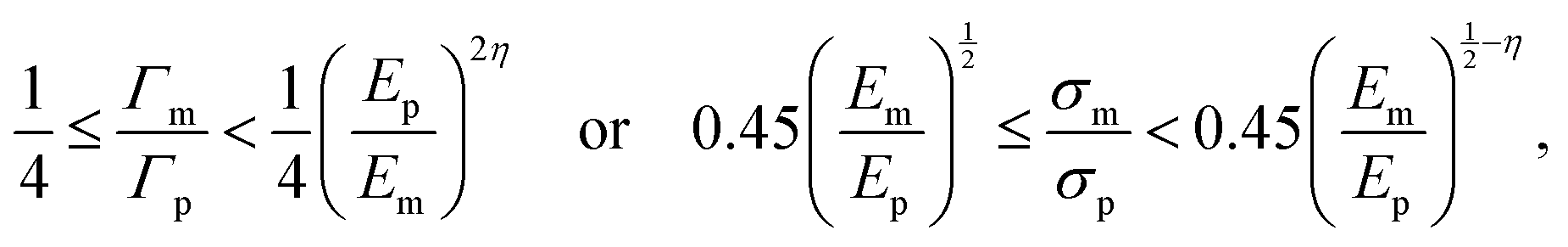
 | (4) |
If Em/Ep = 1, eqn (4) simplifies to Γm/Γp ≤ 0.25, corresponding to the criterion for interfacial crack deflection without elastic mismatch.41 For a crack approaching a platelet/matrix interface, we assess deflection versus penetration using eqn (4).41 Assuming constant matrix and microplatelet strengths at a given length scale, denoted as σm and σp, respectively, we estimate the energy release rate as Γ ∼ σ2/E. The strength criterion for crack deflection then becomes
 | (5) |
If Em/Ep = 1, eqn (5) reduces to σm/σp ≤ 0.5, closely matching the criterion for crack deflection at the interface obtained from FEM simulations.40 Conversely, when the matrix-controlled unit-cell strength exceeds that of the microplatelet (σcm > σcp), the microplatelet fails, leading to crack penetration within the unit cell (Fig. 2c). This strength-based criterion provides a simple design rule when detailed crack-tip fields are not evaluated.32,40
The above analysis indicates that the strength limit of bioinspired AMCs is governed by the failure strength of the microplatelet. The failure strength of AMCs is expressed by
 | (6) |
Fig. 2(c) also reveals an optimal ceramic matrix, corresponding to the condition in which both the matrix and the microplatelet fail simultaneously:
 | (7) |
3. Results and discussion
3.1. Optimization design based on unit cell
To validate the crack-deflection criteria, we systematically vary three key matrix properties: Young's modulus (E), failure strength (σ), and critical energy release rate (Γ). DEM simulations are performed on a representative staggered microstructure unit cell, modeling both matrix and microplatelets as linearly elastic, brittle materials (Fig. 3; see the SI for details). Although the cohesive bonds are brittle, post-failure interfacial mechanics are governed by frictional contact interactions. These interactions naturally capture the nonlinear behavior, specifically the process of interfacial cracking followed by sliding and platelet pull-out, which is responsible for toughening in AMCs. The material contrast between matrix and microplatelets is quantified using three dimensionless ratios: stiffness (Em/Ep), strength (σm/σp), and energy release rate (Γm/Γp). The energy release rate is defined as Γ = σ2l0/(2E), where l0 is the characteristic length in the DEM. To isolate intrinsic interfacial effects from structural factors, we fix the microplatelet aspect ratio at λ = 10, a value exceeding the critical aspect ratio (λ* ≈ 3.2, eqn (2)), beyond which variations become negligible. By eliminating geometric variability, our simulations clearly reveal how matrix and microplatelet property contrasts govern crack deflection. | ||
| Fig. 3 Deformation modes of bioinspired AMCs for different ceramic matrices. (a) Phase diagram based on the energy criterion and (b) phase diagram based on the strength criterion, both plotted against the ratio of Young's modulus (Em/Ep) between the ceramic matrix and microplatelets at an aspect ratio of λ = 10. Black lines are theoretical prediction from the load-transfer model, and red lines reflect modification due to elastic mismatch between the microplatelet and matrix. (c)–(e) Representative deformation modes obtained from DEM simulations: (c) crack deflection, (d) mixed crack, and (e) crack penetration. Markers: squares = deflection, triangles = mixed, circles = penetration. Labeled matrix points (e.g., SiO2, B2O3) are compiled from the literature; the underlying values and sources are provided in the Table 1. | ||
Fig. 3a illustrates the energy-governed phase diagram for crack-deflection behavior across ceramic matrices. Unlike conventional criteria, where crack deflection transitions to penetration at Γm/Γp = 0.25 regardless of stiffness, this boundary broadens significantly for low-stiffness matrices (Em/Ep < 1) due to elastic mismatch between matrix and microplatelets. Eqn (4) with η = 0.125 fits this widened boundary well, indicating that large elastic mismatch between microplatelet and matrix enhances the critical energy release rate of the matrix. Similarly, Fig. 3b presents the strength-governed phase diagram, where the transition boundary follows σm/σp ≈ 0.45(Em/Ep)0.375 (eqn (5)). For matched stiffness Em/Ep = 1, σm/σp ≈ 0.45 aligns with prior FEM results,40 but incorporating elastic mismatch reduces the exponent from 0.5 to 0.375, further raising the critical strength (σm) of the matrix. Consistent with these maps, the DEM snapshots in Fig. 3c–e show the corresponding crack paths in sequence: deflection (Fig. 3c), a mixed mode that combines interfacial deflection with kinked penetration (Fig. 3d), and penetration (Fig. 3e). The improvement in both critical release rate and failure strength for crack deflection reveals that optimal strength and toughness of AMCs are achieved with a low-stiffness matrix. At the optimal matrix condition defined by eqn (7), the mixed-crack mode in Fig. 3d lies on the boundary between deflection and penetration, representing the predicted balance of strength and toughness.
To validate this concept, we examine the load-displacement behavior of the unit cell using DEM simulations (Fig. 4). Fig. 4a presents representative stress–strain responses for three failure modes. In the crack penetration mode (σm/σp = 0.3), the unit cell exhibits linear-elastic behavior with high strength but abrupt failure. In the crack deflection mode (σm/σp = 0.2), nonlinear deformation occurs, featuring a brief plastic-like plateau and lower failure strength, attributed to interfacial crack propagation. By contrast, for the mixed-crack mode (σm/σp = 0.22), the unit cell combines high failure strength comparable to that of crack penetration with nonlinear deformation, enabling simultaneous strength and toughness enhancement. The critical length of interfacial cracks in the crack-deflection mode depends on the microplatelet aspect ratio and saturates at λ = 17λ*.33,42 Once cracks spread throughout the interface, the stress in the unit cell rapidly decreases to a low level due to limited interlayer sliding resistance. In the mixed-crack mode, the crack initiates and propagates along the interface (Fig. 4b), producing the plastic plateau in Fig. 4a, and then deflects into the microplatelet, causing a sudden stress increase. However, microplatelet fracture in this mode reduces interlayer sliding distances compared to pure crack deflection, which in turn lowers energy dissipation efficiency. These results demonstrate that mixed-crack behavior achieves an optimal compromise, balancing strength retention with moderate toughening.
 | ||
| Fig. 4 Mechanical responses of bioinspired AMCs derived from DEM simulations. (a) Normalized tensile stress–strain curves of the unit cell under various ratios of matrix-to-microplatelet fracture strength (σm/σp) at Em/Ep = 0.2. The vertical axis is σ/Ep (stress normalized by the platelet Young's modulus Ep). (b) Initial, propagating, and evolving stages of crack formation in the mixed-crack mode. (c) Normalized failure strength (σf/Ep) and (d) effective toughness (Te/Ep, defined as the area under the stress–strain curve) of the unit cell for different matrices at λ = 10. The white dashed lines mark the deflection–penetration boundary predicted by eqn (7) (the optimal matrix condition). (e) Strain colormap (εxx) under critical loading for various Em/Ep ratios in the unit cell. | ||
Building on the phase diagrams in Fig. 3, which define the regimes of crack deflection and penetration, we quantitatively map how these crack modes govern the failure strength and effective toughness of AMCs across a range of matrix properties (Fig. 4c and d). The contour plot for failure strength (Fig. 4c) reveals that low-stiffness matrices (Em/Ep < 0.2) maximize failure strength, a trend consistent with eqn (6), where strength scales inversely with (Em/Ep)0.125. This behavior stems from the inherent defect sensitivity of ceramics: low-stiffness matrices mitigate stress concentrations in tension zones, as evidenced by DEM-derived strain fields showing increasingly uniform stress distribution as matrix stiffness decreases (Fig. 4e). The effective toughness contour (Fig. 4d) peaks near the crack-deflection transition boundary (white dashed line, eqn (7)), where mixed-crack modes combine high strength with extended nonlinear deformation (Fig. 4b), enabling substantial energy dissipation. Notably, high-stiffness matrices within the crack-deflection regime yield suboptimal toughness despite extended interfacial crack propagation and sliding (eqn (S7)), as excessive stiffness restricts stress redistribution and limits strength.
By synergizing the complementary benefits of a low-stiffness matrix, which redistributes stress to mitigate concentration and improve failure strength, and a low-toughness matrix, which deflects cracks and dissipates energy through interfacial cracking, we demonstrate that bioinspired AMCs attain optimal strength and toughness when the matrix combines low stiffness and controlled low toughness (Fig. 4a and b). DEM simulations identify the ideal matrix properties as Em/Ep = 0.2 and σm/σp = 0.22 for λ = 10. Compared to bulk ceramics (Em/Ep = σm/σp = 1), this design yields a 15% strength improvement and a 2-fold toughness enhancement. Crucially, the small critical aspect ratio (λ* ≈ 3.2, eqn (2)) ensures that optimal performance is largely independent of the aspect ratio (λ) of the microplatelet, simplifying scalable fabrication. The optimal matrix must satisfy the following condition:
 | (8) |
With the optimal matrix condition identified from unit cell, we now examine how interface design controls crack propagation in finite domains, using DEM to resolve deflection, penetration, and mixed modes under tensile loading at fixed Em/Ep = 0.2 while varying σm/σp.
3.2. Tuning fracture propagation through interface design
Fig. 5a illustrates crack propagation under tensile loading (mode I crack) for matrices with Em/Ep = 0.2, simulated in a 6 × 18 unit-cell domain to capture full crack evolution. For a low-strength matrix (σm/σp = 0.2), crack deflection dominates, initiating branching and microplatelet bridging via pullout (Fig. 5b, Video S1), a hallmark of extrinsic toughening. For a transitional-strength matrix, (σm/σp = 0.22), mixed-crack modes emerge (Fig. 5c, Video S2), combining bridging, deflection, and microplatelet fracture to enhance both strength and toughness. However, for a high-strength matrix (σm/σp = 0.3), crack penetration prevails (Fig. 5d), though residual bridging in the low-stiffness matrix marginally improves toughness. Crack deflection angles θ depend on the microplatelet aspect ratio λ, following θ = arctan![[thin space (1/6-em)]](https://www.rsc.org/images/entities/char_2009.gif) λ/2, yielding θ = 78.7° for λ = 10, consistent with experimental observations.19,43 These results confirm that staggered microstructures, coupled with tailored interfaces, activate synergistic toughening mechanisms, such as crack deflection, branching, bridging, and interlayer sliding, to overcome the brittleness of ceramics.
λ/2, yielding θ = 78.7° for λ = 10, consistent with experimental observations.19,43 These results confirm that staggered microstructures, coupled with tailored interfaces, activate synergistic toughening mechanisms, such as crack deflection, branching, bridging, and interlayer sliding, to overcome the brittleness of ceramics.
 | ||
| Fig. 5 Crack propagation in bioinspired ceramics under different matrices with Em/Ep = 0.2. (a) DEM simulation model of a staggered structure subjected to mode I loading with an initial pre-crack of length a0, and b is the specimen width as labeled in the schematic. (b)–(d) Crack paths for σm/σp = 0.2 (b), 0.22 (c), and 0.3 (d), with the crack region highlighted in red. θ is the crack-deflection angle measured by averaging the initial three interface turns. All simulations share the same geometry and pre-crack a0 (aspect ratio λ = 10). An inset in panel (d) illustrates microplatelet bridging in the crack-penetrate case. | ||
To elucidate the toughening mechanisms, we analyze the fracture resistance (R-curves) of bioinspired AMCs with varying matrices (Em/Ep = 0.2) using DEM simulations (Fig. 6). Energy dissipation in staggered microstructures is quantified via the J-integral derived from stress–strain curves (Fig. 6a). Owing to the path independence of the J-integral, we compute it along contours surrounding the crack tip, avoiding stress singularities.19 Crack extension (Δa) is measured through image analysis of crack length at incremental strain steps. Compared to bulk ceramics, AMCs with low-stiffness matrices exhibit higher failure strains (σm/σp = 0.3), which further increase under crack deflection (σm/σp = 0.2, 0.22). While initial fracture toughness improves for σm/σp = 0.3 (Fig. 6b), limited crack extension reflects predominantly linear crack growth. Conversely, crack deflection amplifies Δa by up to 16-fold for σm/σp = 0.2 and 6-fold for σm/σp = 0.22, driving significant energy dissipation and pronounced R-curve toughening (Fig. 6b). Remarkably, despite employing brittle matrices, AMCs achieve plastic-like deformation through interfacial crack propagation and interlayer sliding—mechanisms that mimic ductility in inherently brittle systems. These findings align with experimental observations: pre-cracked AMC samples exhibit plastic-like stress–strain responses due to local toughening mechanisms, while flexural tests retain brittle failure dominated by bulk material behavior.44
 | ||
| Fig. 6 R-curve behavior of bioinspired ceramics under different matrices at Em/Ep = 0.2. (a) Normalized stress–strain curves for the notched staggered structure: vertical axis is σ/Ep (stress normalized by the platelet Young's modulus Ep). All simulations use an initial pre-crack of length a0. (b) Normalized J–R response: vertical axis is J/(Epb), where J is the J-integral, Ep is the platelet Young's modulus, and b is the specimen width (as in Fig. 5a). The horizontal axis is crack extension Δa, defined as the increase in the main-crack length measured by image analysis. (c) Damage ratio versus strain: vertical axis is 100× (broken bonds/total bonds) expressed as a percentage. The green region denotes stable crack growth, while the orange region denotes unstable crack growth. (d) Damage breakdown versus strain using the same color code as in (c): orange = total damage, green = platelet damage, purple = matrix damage. | ||
These trends are quantified by evaluating the damage ratio, defined as the fraction of broken bonds relative to the total number of bonds, from DEM simulations. Fig. 6c demonstrates stark contrasts: bulk ceramics exhibit minimal damage ratio (0.06%), consistent with a straight crack path; crack penetration raises damage ratio to 0.19% via localized microplatelet bridging; and crack deflection amplifies damage to 2.1% due to widespread crack paths and the damage processing zone. In the crack deflection mode (σm/σp = 0.22), we classify crack growth using an energy-consistent proxy based on the evolution of damage with applied strain rather than the force maximum: stable stage corresponds to a gradual, distributed increase in damage; unstable stage is identified by a sharp surge in damage within a small strain increment and the emergence of a spanning microcrack cluster (see Video S1). Using this criterion, about 10% of the total damage accrues in stable stage and ∼90% during unstable stage (Fig. 6c). Notably, exceeding the peak load does not by itself imply instability; stable extension can persist post-peak when the material's crack-growth resistance (R-curve) rises faster than the applied driving force. Within this framework, crack deflection achieves substantial energy dissipation through distributed interfacial damage and bridging prior to coalescence, consistent with toughening mechanisms reported for ceramics and layered composites.22,29,43 Critically, matrix damage ratio constitutes ∼70% of total damage ratio in crack-deflection modes (Fig. 6d), underscoring the decisive role of interfacial properties in enhancing fracture toughness.
Adopting a hierarchical toughening perspective for nacre-like composites,22,39 we estimate a size-dependent amplification by linking unit-cell work-of-fracture gains to the crack-extension window quantified in Fig. 6. Following this view, local gains accumulate as the crack engages successive repeats along its deflected path. Our DEM indicates a ∼2× local (unit-cell) gain for λ = 10; when deflection engages n repeats, the macroscopic amplification is roughly approximated by TAF ≈ 1 + 2nfs, where fs is the fraction of stable extension contributing to the rising R-curve. From Fig. 6b, deflection enlarges Δa by ∼6× relative to a straight path and allocates ∼10% of damage to the stable stage, giving TAF ≈ 1 + 2 × 6 × 0.10 ≈ 2.2 within our DEM window. As the process zone spans more repeats in larger AMCs (e.g., n ∼ 100), the same linear accumulation gives TAF ≈ 1 + 2 × 100 × 0.10 ≈ 21, consistent with hierarchical models in which cooperative deformation across repeats raises toughness with structural extent and with extrinsic toughening frameworks that link rising R-curves to process-zone growth.45
This hierarchical toughening perspective demonstrates that macroscopic performance scales with the number of engaged unit cells, indicating that the theoretical performance limits of AMCs are not solely intrinsic to the constituent materials but are emergent properties of the architectural design and the interface-engineered crack path. To translate this principle into practical guidelines, we next apply our optimization framework to a representative class of high-performance ceramic systems.
3.3. Application to nacre-like alumina ceramics
To illustrate the proposed optimization framework, we consider alumina AMCs integrating various brittle matrices, including TiO2, MgO, SiO2, ZrO2, and B2O3, systems extensively characterized in prior experimental studies (Table 1).9,14–17 For simplicity, the volume fraction of alumina microplatelets is fixed at Φ = 0.9, consistent with experimental ranges (85–95%).13 Given the prevalence of critical stress intensity factor (KIc) measurements in ceramics research, we approximate the energy release rate as Γ = KIc2/E for brittle ceramics under plane-stress condition. On this basis, the energy criterion can be recast as | (9) |
We first examine the strength limit of alumina AMCs. Eqn (6) indicates that the maximum strength of staggered microstructures depends on the intrinsic fracture strength of alumina microplatelets. For example, alumina-B2O3 AMCs exhibit flexural strengths of ∼710 MPa,15 significantly below the theoretical tensile strength of alumina microplatelets σth ≈ 5 GPa. This discrepancy arises because the experimental microplatelet thickness often exceeds 1 µm,13 far surpassing the flaw-insensitive critical thickness h* ≈ 300 nm, thereby introducing size-dependent weakening. Reducing microplatelet thickness below h* could elevate the strength limit of alumina AMCs to ∼2.25 GPa. By comparison, the fracture toughness of monocrystalline alumina is highly anisotropic, with a critical energy release rate of approximately 40 J m−2 or higher when cleaving along the c-plane (0001), yet in the range of 7–24 J m−2 when cleaving along the a-plane (1![[2 with combining macron]](https://www.rsc.org/images/entities/char_0032_0304.gif) 10) or m-plane (1
10) or m-plane (1![[1 with combining macron]](https://www.rsc.org/images/entities/char_0031_0304.gif) 00).49,50 Using Γp = 7–24 J m−2 and h = 1.2 µm,19eqn (6) predicts σf ≈ 893–1654 MPa for crack penetration. For alumina-B2O3 AMCs, the interface properties govern AMC failure strength. Using Γm = 2–4 J m−2,19eqn (1) yields σf ≈ 716–1013 MPa, slightly exceeding experimental values. This overestimation may stem from microplatelet misorientation, a random staggered microstructure, and porosity in actual experiments.
00).49,50 Using Γp = 7–24 J m−2 and h = 1.2 µm,19eqn (6) predicts σf ≈ 893–1654 MPa for crack penetration. For alumina-B2O3 AMCs, the interface properties govern AMC failure strength. Using Γm = 2–4 J m−2,19eqn (1) yields σf ≈ 716–1013 MPa, slightly exceeding experimental values. This overestimation may stem from microplatelet misorientation, a random staggered microstructure, and porosity in actual experiments.
To address the prevalent issue of microplatelet thickness exceeding the critical flaw-insensitive threshold (h* ≈ 300 nm) in AMCs, we propose three strategies to enhance failure strength: (1) introduce a low-stiffness matrix to redistribute stress and mitigate tension-zone concentrations (Fig. 2b). For example, DEM simulations predict a 30% strength increase in alumina-B2O3 AMCs via elastic mismatch. (2) Suppress grain growth during sintering through controlled thermal profiles, high-pressure processing, or matrices that promote anisotropic grain growth.14 This strategy aims for a final platelet thickness near 300 nm after densification. Current nacre-like alumina already uses sub-micrometer platelets, and high-pressure, low-temperature, short-dwell routes such as spark plasma sintering have produced final platelets of about 0.5 µm while maintaining a staggered architecture.11,14 Further grain growth suppression can be achieved by optimizing these sintering parameters and starting from thinner green platelets. (3) Employ moderately reinforced interfaces, such as SiO2 matrices or nanobridge-modified interlayers,32 to guide crack deflection while preserving strength. In alumina-B2O3 AMCs, the predicted strength disparity between crack penetration and deflection regimes suggests that interface reinforcement balances crack control and load-bearing capacity. Notably, the small critical aspect ratio of ceramic matrices ensures failure strength remains independent of microplatelet aspect ratio, simplifying scalable design.
We next assess the toughening limits of alumina AMCs, where crack deflection, enabled by crack branching, microplatelet bridging, and unstable crack growth, serves as the primary toughening mechanism. To activate crack deflection, the matrix must exhibit lower fracture resistance than the alumina microplatelets. Matrices, such as TiO2, MgO, SiO2, and B2O3, satisfy the strength criterion when the failure strength of alumina microplatelet is assumed as σp ≈ 1 GPa (Table 1). However, our theoretical modeling reveals that microplatelet strength depends on thickness, complicating strength criterion-based design. For instance, alumina microplatelets in AMCs (∼1 µm thick) remain flaw-sensitive, while thinner matrices (∼110 nm at Φ = 0.9) approach flaw insensitivity. Regarding the energy criterion, it is generally accepted that crack deflection occurs when Γm/Γp ≤ 0.25.4 Considering the anisotropic critical energy release rate of alumina, the matrix must have Γm ≤ 1.75–10 J m−2, thus leaving a narrow range for selection. Incorporating elastic mismatch broadens this range to Γm ≤ 2.4–13.7 J m−2, permitting only SiO2 and B2O3 as viable candidates. Thus, the energy criterion provides a conservative screening tool, identifying SiO2 and B2O3 as optimal matrices under both strength- and energy-based frameworks (eqn (4) and (9)).
Once crack deflection initiates in alumina AMCs, mechanisms such as crack branching, microplatelet bridging, and unstable crack growth induce nonlinear deformation, evidenced by stress–strain plateaus (Fig. 4a) and enhanced fracture resistance (R-curve) in J-integral assessments (Fig. 6b). Current alumina-SiO2 AMCs achieve fracture toughness KJ up to 17 MPa m0.5,14 corresponding to a toughness amplification factor (TAF) of 4.8 relative to bulk alumina. While this remains below 40-fold TAF of natural nacre,6 two strategies can narrow the gap: (1) adopting tougher matrices can elevate failure strength. For instance, the maximum σf predicted for h = 500 nm is 1.28 GPa, nearly triple the experimental value of 470 MPa in alumina-SiO2 AMCs.14 By adopting a tougher matrix, the maximum strength predicted by eqn (6) can be achieved, yielding TAF = 13.1, consistent with residual-stress-enhanced artificial nacre.6 (2) Expanding the number of engaged unit cells along the deflected crack path, which increases Δa and accumulates the stable-growth contribution to the rising R-curve; in our scaling, the amplification follows TAF ≈ 1 + 2nfs with fs ≈ 10.0% from Fig. 6c. In ASTM E1820 tests conducted on 14 × 2 × 2 mm3 samples and 0.5 µm microplatelet thickness,51 there are around 2000 unit cells along the crack direction, exceeding that modeled in our DEM simulations and prior numerical studies.28,31 If the microplatelet thickness is further reduced below 300 nm (assuming no grain growth), the number of unit cells rises by 1.67, leading to an estimated TAF ≈ 21.8, consistent with our DEM-based scaling. This size-coupled toughening agrees with experiments in which alumina AMCs show increasing fracture toughness with specimen size.43 Natural nacre further enhances TAF via nano-asperities at interfaces, which promote strain hardening and suppress localization during interlayer sliding,28,52 a design principle adaptable to ceramic composites through interface engineering.
To reconcile the trade-off between strength and toughness, optimizing alumina AMCs necessitates balancing the following mechanisms: (1) employing a low-stiffness matrix to redistribute local stresses and lessen stress concentrations, which favors low-modulus ceramics such as SiO2 and B2O3; (2) minimizing microplatelet thickness to curtail flaw sensitivity, thus requiring effective grain-growth control during sintering; (3) ensuring the matrix is sufficiently weak to induce crack deflection, yet strong and tough enough to approach the critical boundary defining crack deflection, thereby enhancing energy dissipation (eqn (8)); (4) recognizing that failure strength remains largely independent of aspect ratio, while plasticity increases at higher aspect ratios, implying λ ≈ 17λ* as optimal;33,42 (5) incorporating additional toughening mechanisms, for instance nano-asperities, residual stress, or phase transformations, to further increase the TAF.6,52,53
These design rules establish a set of target properties that directly address the historical conflict between designing “interfaces that toughen” and employing “processes that densify”.27 By specifying optimal ranges for matrix stiffness, interfacial toughness, and microplatelet thickness, this framework provides clear, quantitative targets to guide processing conditions. These targets are derived from the deflection and penetration criteria in eqn (4) and (5), which are parameterized with bulk properties like modulus, strength, and toughness to enable rapid screening of candidate materials. In this way, the present study provides a physics-based map that links target interfacial stiffness and fracture toughness to macroscopic strength–toughness combinations in AMCs. It does not resolve the detailed atomic structure or chemistry of alumina–matrix interfaces. Such information is typically obtained from HRTEM, XPS, nanoindentation or micro-cantilever tests and will be essential in future experimental work. These measurements can connect the effective parameters used here to specific processing routes and interphase compositions,11,14 and can also verify interphase chemistry and adhesion while guiding the design of nano-asperities or nanobridges that tune mechanisms and achieve the targeted bulk properties.16,17 The practical realization of these ideal interfaces in all-ceramic systems, however, introduces complexities related to sintering kinetics and interfacial bonding that we now discuss.
3.4. Additional remarks on interface design
While we emphasize the importance of interfacial toughness, defined here as the energy release rate of the ceramic-based matrix, the actual bonding strength between microplatelet and matrix, governed by sintering-driven diffusion, also critically influences the strengthening and toughening of alumina AMCs. This distinction, however, does not undermine our conclusions, as interfacial toughness can be approximated by the lower value of either matrix critical energy release rate or interfacial bond strength. Assuming robust microplatelet–matrix bonding, typical in high-density AMCs, equating interfacial toughness to matrix critical energy release rate simplifies the screening of optimal matrices. Besides, if crack deflection induces matrix deformation, the associated strain energy contributes to effective interfacial toughness. Under linear elasticity, this contribution is estimated as Γm ≈ σm2tm/2Em, where tm is the thickness of the matrix (see SI Fig. S1). Thus, minimizing matrix thickness reduces effective interfacial toughness,54 a strategy achievable through controlled sintering.Material selection is further constrained by the positive correlation between stiffness, strength, and toughness in ceramics, evident in Ashby plots.55 Thus, low-stiffness ceramics (e.g., B2O3, SiO2), typically with lower toughness, are preferred for matrices. Two strategies emerge: (1) prioritize amorphous interfaces (e.g., borosilicate glass) or induce localized amorphization. (2) For crystalline matrices, weaken interfaces via defect engineering (e.g., polycrystalline grain boundaries) or nanoscale porosity. For alumina AMCs, matrices like B2O3 and SiO2 exhibit fracture energies near the upper limit for crack deflection (Fig. 3a), leaving little margin for error.14,19 Local toughening mechanisms,19 such as residual stresses from thermal expansion mismatches,53,56 could expand this window and enable deflection even with stronger and tougher matrices, although further study is needed.
Our framework primarily applies to AMCs with uniform matrices and focuses on brittle fracture in oxide ceramics at the microplatelet scale. In this regime, strength and toughness are governed by elastic modulus and energy-release rate, and nonlinear response arises from interfacial cracking followed by sliding. Dislocation-mediated plasticity in nanostructured oxides, which becomes important below approximately 100 nm, is not considered here and is a direction for future work.18,32 Although high-strength and/or high-toughness ceramics like TiO2 and ZrO2 are unsuitable for crack deflection-dominated designs,16,54 crack control remains achievable by suppressing grain growth to maintain nanoscale matrix dimensions and by introducing nanobridges that locally reduce interfacial strength and toughness, which promotes deflection.16,17 These cases align qualitatively with our model but require quantitative refinement. Besides, our framework targets all-ceramic AMCs with oxide–oxide interfaces formed by sintering, which are less sensitive to ambient humidity and corrosion than polymer- or metal–matrix systems.57 Humidity can lower alumina strength through water-assisted slow crack growth, but the same criteria remain applicable, and environment-dependent strength and energy-release rates can be inserted into eqn (4) and (5) without changing the design logic. Ultimately, our analysis highlights the governing role of microplatelet thickness and interfacial toughness in balancing strength and toughness, and emphasizes that sintering conditions govern practical feasibility.
4. Conclusion
This study establishes universal strength and energy criteria for AMCs, derived through a simplified load-transfer model and DEM simulations. These criteria, independent of microplatelet aspect ratio, reveal that low-stiffness matrices (e.g., SiO2, B2O3) redistribute stress to mitigate localized concentrations, enhancing fracture strength, while weak interfaces promote crack deflection, activating extrinsic toughening mechanisms such as crack branching, microplatelet bridging, and unstable crack growth. Using alumina AMCs as a model system, we identify microplatelet thickness and interfacial toughness as the primary factors underlying experimental-theoretical discrepancies. Reducing microplatelet thickness toward about 300 nm, as suggested by our flaw insensitive thickness estimate, together with the use of low stiffness matrices would in principle enable AMCs to approach their theoretical strength limit of 2.25 GPa, provided that future processing routes can effectively suppress grain growth to this scale. Critically, the matrix must balance dual requirements: weak enough to enable crack deflection but sufficiently cohesive to operate near the crack-deflection threshold, maximizing energy dissipation. By optimizing matrix toughness and microplatelet thickness, our framework predicts a toughening amplification factor of up to 21.8 for alumina AMCs under current experimental protocols. Framed in the metamaterials context, these results show that tuning ceramic–ceramic interfaces directly programs the crack path and the rising R-curve, enabling programmable, damage-tolerant responses in all-ceramic, nacre-like architectures. The resulting design map provides actionable targets for materials selection and processing, helping bridge biological inspiration and scalable ceramic fabrication.Author contributions
Zezhou He: conceptualization, methodology, software, validation, investigation, writing – original draft, writing – review & editing. Rohit Pratyush Behera: experimental investigation, writing – original draft, writing – review & editing. Huajian Gao: conceptualization, writing – review & editing, supervision. Hortense Le Ferrand: conceptualization, writing – review & editing, supervision.Conflicts of interest
The authors declare that they have no known competing financial interests or personal relationships that could have appeared to influence the work reported in this paper.Data availability
The data supporting this article have been included as part of the supplementary information (SI). The supplementary information file contains additional details on the shear-lag model, fracture-mechanics derivations, and discrete-element simulations (including model parameters); Fig. S1–S2, which illustrate the staggered platelet–matrix unit cell, interface mechanics, and modulus-mismatch scaling from DEM; Tables S1–S2, which compile the specific strength and toughness data used in Fig. 1 and provide a glossary of symbols and variables; and supplementary videos S1–S2, which show representative crack paths and process-zone evolution in the DEM simulations. See DOI: https://doi.org/10.1039/d5mh01962a.Acknowledgements
The authors acknowledge funding from the Ministry of Education of Singapore (award MOE-T2EP50122-0021). The computational work for this article was fully performed on resources of the National Supercomputing Centre, Singapore (https://www.nscc.sg).References
- H. D. Espinosa, J. E. Rim, F. Barthelat and M. J. Buehler, Prog. Mater. Sci., 2009, 54, 1059–1100 CrossRef CAS.
- M. A. Meyers, J. McKittrick and P.-Y. Chen, Science, 2013, 339, 773–779 CrossRef CAS PubMed.
- U. G. K. Wegst, H. Bai, E. Saiz, A. P. Tomsia and R. O. Ritchie, Nat. Mater., 2015, 14, 23–36 CrossRef CAS PubMed.
- F. Barthelat, Z. Yin and M. J. Buehler, Nat. Rev. Mater., 2016, 1, 16007 CrossRef CAS.
- L.-B. Mao, H.-L. Gao, H.-B. Yao, L. Liu, H. Cölfen, G. Liu, S.-M. Chen, S.-K. Li, Y.-X. Yan, Y.-Y. Liu and S.-H. Yu, Science, 2016, 354, 107 CrossRef CAS PubMed.
- Y.-F. Meng, Y.-B. Zhu, L.-C. Zhou, X.-S. Meng, Y.-L. Yang, R. Zhao, J. Xia, B. Yang, Y.-J. Lu, H.-A. Wu, L.-B. Mao and S.-H. Yu, Adv. Mater., 2022, 34, 2108267 CrossRef CAS PubMed.
- Y. Ni, Z. Song, H. Jiang, S. Yu and L. He, J. Mech. Phys. Solids, 2015, 81, 41–57 CrossRef.
- E. Munch, M. E. Launey, D. H. Alsem, E. Saiz, A. P. Tomsia and R. O. Ritchie, Science, 2008, 322, 1516–1520 CrossRef CAS PubMed.
- L. J. Bonderer, A. R. Studart and L. J. Gauckler, Science, 2008, 319, 1069 CrossRef CAS PubMed.
- Z. Yin, F. Hannard and F. Barthelat, Science, 2019, 364, 1260–1263 CrossRef CAS PubMed.
- H. Le Ferrand, F. Bouville, T. P. Niebel and A. R. Studart, Nat. Mater., 2015, 14, 1172–1179 CrossRef CAS PubMed.
- A. Wat, J. I. Lee, C. W. Ryu, B. Gludovatz, J. Kim, A. P. Tomsia, T. Ishikawa, J. Schmitz, A. Meyer, M. Alfreider, D. Kiener, E. S. Park and R. O. Ritchie, Nat. Commun., 2019, 10, 961 CrossRef PubMed.
- F. Bouville, J. Mater. Res., 2020, 35, 1076–1094 CrossRef CAS.
- F. Bouville, E. Maire, S. Meille, B. Van de Moortèle, A. J. Stevenson and S. Deville, Nat. Mater., 2014, 13, 508–514 CrossRef CAS PubMed.
- P. I. B. G. B. Pelissari, F. Bouville, V. C. Pandolfelli, D. Carnelli, F. Giuliani, A. P. Luz, E. Saiz and A. R. Studart, J. Eur. Ceram. Soc., 2018, 38, 2186–2193 CrossRef CAS.
- M. Grossman, F. Bouville, K. Masania and A. R. Studart, Proc. Natl. Acad. Sci. U. S. A., 2018, 115, 12698–12703 CrossRef CAS PubMed.
- W. Woigk, E. Poloni, M. Grossman, F. Bouville, K. Masania and A. R. Studart, Proc. Natl. Acad. Sci. U. S. A., 2022, 119, e2118868119 CrossRef CAS PubMed.
- R. P. Behera, A. Y. R. Ng, M. J.-H. Reavley, Z. Du, C. L. Gan and H. Le Ferrand, Cell Rep. Phys. Sci., 2024, 5, 102140 CrossRef CAS.
- V. Vilchez, S. Rawson, S. Zhou, J. McGregor, M. Lawson, A. Rack, Y. Chen, P. J. Withers and F. Bouville, Acta Mater., 2024, 280, 120338 CrossRef CAS.
- O. T. Picot, V. G. Rocha, C. Ferraro, N. Ni, E. D’Elia, S. Meille, J. Chevalier, T. Saunders, T. Peijs, M. J. Reece and E. Saiz, Nat. Commun., 2017, 8, 14425 CrossRef CAS PubMed.
- Y. Shao, H.-P. Zhao, X.-Q. Feng and H. Gao, J. Mech. Phys. Solids, 2012, 60, 1400–1419 CrossRef.
- F. Barthelat and R. Rabiei, J. Mech. Phys. Solids, 2011, 59, 829–840 CrossRef.
- L. S. Dimas and M. J. Buehler, J. Mater. Res., 2013, 28, 1295–1303 CrossRef CAS.
- F. Barthelat, J. Mech. Phys. Solids, 2014, 73, 22–37 CrossRef.
- H. Gao, B. Ji, I. L. Jäger, E. Arzt and P. Fratzl, Proc. Natl. Acad. Sci. U. S. A., 2003, 100, 5597 CrossRef CAS PubMed.
- Z. Yu, J. Liu, W. Zhu and X. Wei, Compos. Struct., 2018, 206, 621–627 CrossRef.
- W. J. Clegg, K. Kendall, N. M. Alford, T. W. Button and J. D. Birchall, Nature, 1990, 347, 455–457 CrossRef CAS.
- N. Abid, M. Mirkhalaf and F. Barthelat, J. Mech. Phys. Solids, 2018, 112, 385–402 CrossRef.
- N. Abid, J. W. Pro and F. Barthelat, J. Mech. Phys. Solids, 2019, 124, 350–365 CrossRef.
- Z. He, Y. Zhu, J. Xia and H. Wu, J. Mech. Phys. Solids, 2019, 133, 103706 CrossRef CAS.
- K. Radi, D. Jauffres, S. Deville and C. L. Martin, Composites, Part B, 2020, 183, 107699 CrossRef CAS.
- K. Radi, D. Jauffrès, S. Deville and C. L. Martin, J. Mech. Phys. Solids, 2019, 126, 101–116 CrossRef CAS.
- Z. Yu, J. Liu and X. Wei, Compos. Sci. Technol., 2018, 156, 262–268 CrossRef CAS.
- F. Ma, J. H. Wu and M. Huang, J. Phys. D: Appl. Phys., 2015, 48, 465305 CrossRef.
- F. Ma, C. Wang, Y. Du, Z. Zhu and J. H. Wu, Mater. Horiz., 2022, 9, 653–662 RSC.
- Z. He, Y. Zhu and H. Wu, J. Mech. Phys. Solids, 2022, 158, 104560 CrossRef.
- H. Gao, Int. J. Fract., 2006, 138, 101 CrossRef.
- E. Feilden, T. Giovannini, N. Ni, C. Ferraro, E. Saiz, L. Vandeperre and F. Giuliani, Scr. Mater., 2017, 131, 55–58 CrossRef CAS.
- B. Ji and H. Gao, Annu. Rev. Mater. Res., 2010, 40, 77–100 CrossRef CAS.
- M. Ju, X. Li, X. Li and G. Zhang, Eng. Fract. Mech., 2022, 263, 108297 CrossRef.
- H. Ming-Yuan and J. W. Hutchinson, Int. J. Solids Struct., 1989, 25, 1053–1067 CrossRef.
- Z. Song, Y. Ni, L. Peng, H. Liang and L. He, Sci. Rep., 2016, 6, 23724 CrossRef CAS PubMed.
- V. Vilchez, P. I. B. G. B. Pelissari, V. C. Pandolfelli and F. Bouville, J. Eur. Ceram. Soc., 2023, 43, 4472–4481 CrossRef CAS.
- T. Magrini, S. Moser, M. Fellner, A. Lauria, F. Bouville and A. R. Studart, Adv. Funct. Mater., 2020, 30, 2002149 CrossRef CAS.
- Z. Zhang, Y.-W. Zhang and H. Gao, Proc. R. Soc. B, 2011, 278, 519–525 CrossRef PubMed.
- J. Cui, W. Zhao, K. Guan and P. Rao, J. Aust. Ceram. Soc., 2020, 56, 1229–1235 CrossRef CAS.
- D.-H. Chung, Philos. Mag., 1963, 8, 833–841 Search PubMed.
- J. Salem, Int. J. Appl. Ceram. Technol., 2023, 20, 938–950 CrossRef CAS.
- S. Graça, V. Trabadelo, A. Neels, J. Kuebler, V. Le Nader, G. Gamez, M. Döbeli and K. Wasmer, Acta Mater., 2014, 67, 67–80 CrossRef.
- T. Vodenitcharova, L. C. Zhang, I. Zarudi, Y. Yin, H. Domyo, T. Ho and M. Sato, J. Mater. Process. Technol., 2007, 194, 52–62 CrossRef CAS.
- ASTM Book of Standards, 2013, Copyright, pp. 1–54 DOI:10.1520/E1820-13.
- H. Li, K. Geng, B. Zhu, Q. Zhang, Y. Wen, Z. Zhang, Y. Yuan and H. Gao, J. Mech. Phys. Solids, 2024, 190, 105712 CrossRef.
- R. Bermejo and R. Danzer, Eng. Fract. Mech., 2010, 77, 2126–2135 CrossRef.
- K. Golovin, A. Dhyani, M. Thouless and A. Tuteja, Science, 2019, 364, 371–375 CrossRef CAS PubMed.
- M. F. Ashby, Materials Selection in Mechanical Design, Butterworth-Heinemann, Oxford, 3rd edn, 2005 Search PubMed.
- R. Henry, H. Saad, S. Dankic-Cottrino, S. Deville and S. Meille, J. Eur. Ceram. Soc., 2022, 42, 2319–2330 CrossRef CAS.
- S. Liu, J. Deng, H. Zhao, T. Wang, J. Lu, B. Ding, T. Guo, R. O. Ritchie and L. Guo, Nat. Commun., 2025, 16, 5980 CrossRef CAS PubMed.
| This journal is © The Royal Society of Chemistry 2026 |