DOI:
10.1039/D5MH01784J
(Review Article)
Mater. Horiz., 2026,
13, 2683-2700
Boosting mechanical-to-ionic transduction for self-powered piezoionic sensing
Received
18th September 2025
, Accepted 14th November 2025
First published on 5th December 2025
Abstract
In the realm of sensing, piezoionic systems have emerged as innovative tools for perceiving tactile sensations through mechanical-to-ionic transduction, mimicking biological signal production and transmission. To date, the biomimetic transduction mechanism and strategies for engineering the transduction efficiency remain not fully understood and underutilized. This review provides the fundamentals of mechanical-to-ionic transduction for efficient self-powered sensing, identifying the most crucial structural and operating parameters governing the generation of a transient signal output with respect to the migration and redistribution of ions upon mechanical stimulation. It also examines the recent strategies for efficiently converting mechanical keystrokes into electrical signals through performance-driven structural design, thereby maximizing piezoionic voltage generation. This involves engineering ion transport and fluid flow through porosity, microphase separation, conductive pathways and structural gradients. With respect to piezoionic effect-based applications, this review highlights the promising potential of polymeric, ionic materials in soft wearable electronics, ionic skins, tissue engineering, biointerfaces and energy harvesting.
Wider impact
Piezoionic materials operate through mechanical-to-ionic transduction, generating transient voltages as ions of different mobilities separate under mechanical stimulation. Although the piezoionic effect is relatively new and its working principle is not yet fully understood, this review provides both material structural design guidelines for enhancing device performance and fundamental insights into the underlying transduction mechanisms. In addition, it outlines conceptual frameworks for translating the piezoionic effect into practical devices, emphasizing the role of operating parameters in voltage generation and strategies for engineering fluid-driven ion transport to further boost piezoionic responses.
|
From cellular mechanotransduction to biomimetic electromechanical transducers
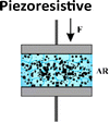
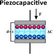
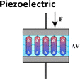
Mechanotransduction is the process by which cells sense a mechanical force and convert it into a biochemical response.1 As a cornerstone of the somatosensory system, this process supports critical physiological functions at various levels from whole-body systems to cellular and molecular processes including hearing, touch perception, and muscle contraction.1,2 Maksimovic et al.3 identified key proteins in skin mechanoreceptors that display touch-activated ionic currents, facilitating high spatio-temporal acuity for tactile perception. Under mechanical stimulation, the mechanosensitive ion-channel-based receptors transition between open and closed states. This creates an ion influx and generates an action potential which is relayed to the brain by the somatosensory system (Fig. 1).3–5 Low-threshold mechanoreceptors are adapted to detect a particular stimulus and have a working range of frequency.6–8 Merkel cell receptors optimally detect pressures below 2 Hz, Meissner corpuscles respond best to skin movement and dynamic motion at 2–40 Hz, and Pacinian corpuscles are tuned to vibrations within a 40–200 Hz range.8 Inspired by these natural mechanisms, soft electromechanical transducers have been designed for detecting small changes in force, displacement, or vibration, converting the resulting mechanical stimuli into electrical signals.9 While being increasingly valued for applications ranging from soft robotics to health monitoring, their most common transduction mechanisms include, until recently, piezoresistive, piezocapacitive, and piezoelectric mechanisms (Table 1).10–13 Despite their sensitivity to temperature, high hysteresis, poor linearity and long relaxation times, piezoresistive transducers are capable of functioning over a wide range of detection-measuring pressures (ca. 1 Pa–1 MPa) due to changes in resistance as a result of local mechanical deformations.14–19 Piezocapacitive transducers, are still prone to hysteresis and to interferences (such as parasitic charges or electromagnetic noise) and offer relatively high sensitivity to small pressures (ca. 1 Pa–1 MPa), good temperature independence, and low power consumption. These features rely on the formation of an electrical double layer (EDL) at the dielectric–electrode interface, which can detect changes in capacitance through alterations in plate distance or electrical permittivity.20–27 Distinguished by their high sensitivity, fast response time, mechanical flexibility, and chemical stability, piezoelectric transducers employ the ferroelectric properties of some (semi-)crystalline and glassy materials to generate electrical charges caused by stress-induced dipole rearrangement under dynamic or transient loads.28–35 However, to achieve optimal piezoelectric performance, these materials require a poling step to align the dipole within the materials, and the range of pressure detected is generally higher (ca. 100 Pa to 10 MPa).
 |
| | Fig. 1 Mechanisms underlying the tactile perception and the different low-threshold mechanoreceptors on skin. Human skin mechanoreceptors transduce tactile stimuli into action potentials, which are transmitted via the afferent nervous system to synaptic junctions. At the synapses, action potentials relay the information to the brain, giving rise to a complex multilevel feature of tactile perception. | |
Table 1 Conceptual distinction between piezoresistive, piezocapacitive, piezoelectric and piezoionic electromechanical transducers
|
|
|
|
|

|
| Transduction mechanism |
Change in the percolation or conductive pathways |
Alterations in plate distance or electrical permittivity |
Change in polarization |
Ion redistribution |
| Signal output |
Change in resistance (ΔR) |
Change in capacitance (ΔC) |
Voltage generation (V) |
Ionic potential change (ΔV) |
| Current change (ΔI) |
|
Current change (ΔI) |
Current change (ΔI) |
| Signal output range |
10–10![[thin space (1/6-em)]](https://www.rsc.org/images/entities/char_2009.gif) 000 Ω 000 Ω |
0.001–1 nF |
0.01–10 V |
1–500 mV |
| Detection pressure range |
1 Pa–1 MPa |
1 Pa–1 MPa |
100 Pa–10 MPa |
1 Pa–100 kPa |
| Sensitivity |
1–1000 kPa−1 |
1–100 kPa−1 |
0.1–100 kPa−1 |
0.001–100 kPa−1 |
| Response time |
ms–s |
ms–s |
ms–s |
ms–s |
| Recovery time |
ms |
ms |
ms |
0.1 s–10 s |
| Advantages |
Good stability |
Good temperature independence |
Self-powered |
Self-powered |
|
|
|
Mechanical and chemical stability |
Good linearity |
|
|
Low power consumption |
High output voltage |
Mechanically soft and deformable |
| Disadvantages |
Temperature sensitive |
Prone to hysteresis and to interferences |
Only detect dynamic or transient loads |
Moisture and temperature sensitive |
| High hysteresis |
External power supply required |
Poling required |
Low output voltage |
| Poor linearity |
|
Mechanically rigid |
|
| Long relaxation time |
|
|
|
| External power supply required |
|
|
|
Inspired by biological systems, ionotronic devices, which couple electron and ion movement, have led to the development of mechanical-to-ionic transducers, such as piezoionics. These transducers operate via the flow of ions in a fluid or solid electrolyte.9,10,36 The piezoionic effect relies on the newly discovered electromechanical conversion phenomenon that occurs when a non-uniform mechanical deformation is applied to ion-embedded materials. This generates a transient voltage based on the separation of ions (cations and anions of different mobilities in the fluid transport).37–39 Often mistaken for piezocapacitive transducers due to the similarity of materials employed, piezoionic transducers afford a highly sensitive mechanical detection (ca. 1 Pa to 100 kPa) with a reliable linear response when converting mechanical loads into a proportional self-powered voltage output.37–46 A fundamental distinction lies in the power dependence, as piezoresistive and piezocapacitive transducers require an external power supply to operate, whereas piezoelectric and piezoionic transducers are self-powered and generate an electrical signal autonomously. Additionally, piezoelectric transducers are rather rigid, crystalline materials that generate voltage (ca. 0.01–10 V) through an atomic dipole displacement. In contrast, piezoionic transducers rely on mechanically induced ion migration within soft, deformable, ionically conductive materials for generating a transient voltage (ca. 1–500 mV).37–46 Up to now, piezoionic transducers exhibit a response time in the range of milliseconds to seconds, but a slow recovery time in the range of tenths of a second to tens of seconds when compared to other types of electromechanical transducers. Overall, the electromechanical performance of soft electromechanical transducers is dictated by major parameters, such as the sensitivity, detection limit, operating pressure range, response time, self-powering and linearity. These attributes enable soft electromechanical transducers to be easily integrated and to continuously monitor and detect a wide range of mechanical loads with high resolution.10–13 To this end, Table 1 provides a conceptual comparison of different electromechanical transducers based on a survey of the current state-of-the-art developments in terms of their sensitivity and maximum pressure limit, as shown in Fig. 2. From an application standpoint, the detection pressure range of piezoionic transducers makes them promising candidates for wearable sensors and electronic skin technologies. Their high sensitivity to subtle forces, combined with their self-powered voltage output and good linearity, allows them to detect mechanical stimuli ranging from ultra-light touch to soft deformations, i.e., well within the sensitivity range of human skin, which typically begins to perceive pressure around 10–100 Pa.
 |
| | Fig. 2 Sensitivity (kPa−1) and maximum pressure limit (kPa) of common piezoresistive, capacitive, piezoelectric and piezoionic electromechanical sensors. | |
There are several reviews that previously introduced the piezoionic effect emphasizing their historical evolution, scientific description, methodology, application, and outlook.47,48 Ho et al.47 provided a holistic overview of the early conceptualization of piezoionics as a biomimetic mechanical–electrical transduction mechanism, and Chen et al.48 highlighted the different types of piezoionic materials and methods for enhancing the piezoionic response. In contrast, this review serves as a guide for newcomers to the field as it provides insights into the fundamentals of the mechanical-to-ionic transduction, including an up-to-date description of recently used polymeric ionic materials, and the crucial structural and operating parameters governing their voltage generation. Moreover, the recent innovative strategies for engineering ion transport, fluid flow for maximizing piezoionic performance and a brief exploration of relevant applications are addressed in the review.
Conceptual frameworks for mechanical-to-ionic transduction
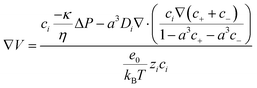
Initially identified within ionic gels by De Gennes et al.,49 the concept of mechanical-to-ionic transduction was coined as the piezoionic effect by Sarwar et al.37 The piezoionic effect is the transient separation between anionic and cationic species in response to an applied mechanical stress (Fig. 3).38,39 Under mechanical stimulation, a fluid pressure gradient is created, which drives fluid flow within a matrix. As a result, cations and anions are carried by the fluid flow, but at different speeds due to their different mobilities and interaction with the polymer matrix. This in turn generates a transient voltage according to the leading/dominant ion (the most mobile).38,39 Overall, the generated potential generally exhibits a linear relationship with the pressure gradient, as shown in eqn (1):where α is the piezoionic coefficient (change in output voltage per stress), ΔP is the pressure gradient, and ΔV is the generated potential.38 Yet, the working principle of piezoionics is not fully understood, and its theoretical foundations remain to be clarified. Nonetheless, several models have been proposed to explain the newly discovered mechanical-to-ionic transduction phenomenon. More particularly, the streaming potential44 and Poisson-Nernst-Planck coupled with fluid mechanics have been developed to describe the piezoionic effect.38,39 The streaming model describes the potential generated by electrolyte movement through a charged structure such as a capillary or porous medium, as defined in eqn (2):| |  | (2) |
where σ is the ionic conductivity, ΔP is the pressure gradient, κ is the permeability, η is the fluid viscosity, N is the concentration of ions per cubic meter, and e is the fundamental charge.44,49 The streaming model accurately predicts the electrical potential over a broad pressure range. The streaming potential primarily arises from convective flux, where fluid movement under pressure carries ions downstream, leading to charge accumulation and electrical potential generation.44,49 Although being effective for piezoionic systems built on a single mobile ion, this model is inaccurate for ion pairs (involving two mobile ions) since it only considers the transport of ions within the fluid flow due to the generation of a pressure gradient. As a result, the model suggests that the larger the fluid flow speed, the higher the piezoionic response.44,49
 |
| | Fig. 3 Structural parameters affecting the fluid-driven ion transport, including ion mobility, material dimensions, charge density, crosslinking density, material density (left, red to yellow for material selection), porosity, microphase separation, gradient structure and conductive pathways (right, green to purple for structural design). | |
The Poisson–Nernst–Planck (PNP) equations are another foundation for studying ion transport in fluids, describing ionic transport under the influence of gradients and electric fields.38,39,50,51 The Nernst–Planck equation considers ion transport based on the mass transport phenomena of diffusion, electromigration, and convection, whereas the Poisson equation explains the spatial charge distribution of ions, owing to an electric field; these equations are respectively shown in eqn (3) and (4), where Ji is the ion flux, Di is the diffusion coefficient of ion i, ci is the concentration of such ion, zi is the electron valence of the ion, kB is the Boltzmann constant, T is temperature, e is the fundamental charge, ν is the flow velocity, V is the electrical potential, and ε is the permittivity of the medium:38,39,50,51
| |  | (3) |
| |  | (4) |
This model can effectively capture ion movement in biological systems, such as cells and channels.
50,51 Nevertheless, the PNP model has limitations, such as neglecting ion–ion interactions, steric hindrance, and finite volume effects.
52,53 As such, a modified PNP model considering such effects led to
eqn (5) where the term
a3 is the spacing between densely packed ions, which correlates to the concentration limit,
a3 = 1/
cmax:
52,53| | 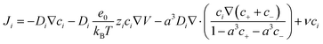 | (5) |
As mechanical-to-ionic transduction critically depends on fluid flow to generate a transient voltage with respect to the transient separation of cations and anions at different speeds, it can be mechanistically analyzed by Darcy's law. The latter describes the velocity of a fluid traveling through a porous medium with respect to
eqn (6), where
ν is the flow velocity,
κ is the permeability,
η is the viscosity, and Δ
P is the pressure gradient:
38| |  | (6) |
Dobashi
et al.38 combined the PNP equations (
eqn (3) and (4)) with Darcy's law (
eqn (6)) to better understand the mechanical-to-ionic transduction in dilute media, where ion–ion interactions are negligible, as well as for ion-pair systems (involving two mobile ions). This leads to
eqn (7), where
N is the number of ions,
e is the fundamental charge,
κ is the permeability,
η is the viscosity,
σ is the conductivity,
D0+ and
D0− are the diffusion coefficients of the cation and anion without drag forces and interactions with the matrix, respectively, while
D+ and
D− are the effective diffusion coefficients of the cation and anion, respectively:
38| |  | (7) |
In the present model, mechanical stress creates a fluid flow (convective flux) that drives ionic movement and induces charge separation due to differences in ion mobility.
38 Unlike the streaming model (
eqn (2)), the latter approach considers not only fluid-driven ion transport, but also the different mobilities of individual ions. As a result, the dominant ion (the most mobile) drives the voltage generation with respect to the diffusion coefficients, which in turn depend on ion size, matrix porosity, permeability, and ion–matrix interactions. Therefore, a larger fluid flow speed and larger mobility difference between the ions produce a higher output voltage.
38 Wang
et al.52 proposed a different model based, this time, on the modified PNP (
eqn (5)) coupled with Darcy's law (
eqn (6)), yielding
eqn (8):
| |  | (8) |
While the previous model considered the spacing of ions and ion–ion interactions, the latter equations (
eqn (7) and (8)) have been successfully applied to ion-pair systems, appropriately predicting their voltage generation.
52
Sensor composition and structural design factors affecting piezoionic performance
Piezoionic transducers operate by mechanically stimulating a polymer matrix or a gel, which generates a fluid pressure gradient that, in turn, drives ion flow within the matrix. As a result, a transient separation between the cations and anions takes place due to their different mobilities and interaction, breaking electrical neutrality and generating a transient voltage.38,39 Thus, the polymer matrix and the ions are among the key factors influencing the performance of a piezoionic sensor. Structural parameters, such as the type of polymer matrix, its dimensions, the nature and mobility of the ions, the presence of liquid ion transporters, the charge density, the crosslinking density, porosity, microphase separation, and the introduction of a predetermined gradient of ions, significantly affect fluid-driven ion transport (Fig. 3). In the following sections, we will examine and analyse each of these structural parameters in detail. Unfortunately, unlike to the well-established measurement of ionic conductivity or the cycling of batteries, there is no common practice for the assembly and testing of piezoionic sensors. This makes the comparison of the results and performance analysis of the reported sensors quite a challenging task. Thus, we propose evaluating their performance based on the generated voltage range and the levels of applied pressure or strain forces. The key considerations include the maximum generated voltage, which facilitates future sensor applications, and the minimum applied force, which determines the device's sensitivity. These performance parameters are summarized in Table 2. Another important parameter for evaluating sensor performance is the response speed, or relaxation time, that is, the time required for the sensor to return to its initial state and become ready to generate a new response. However, the majority of reported studies have concentrated on the dependence of generated voltage on the applied mechanical force, whereas only a limited number have examined repeated cycling, which is necessary for assessing the relaxation time. Consequently, this parameter was not considered in this current review. As a result, piezoionic sensors can be categorized as follows:
Table 2 Polymeric ionic materials and their electromechanical performance of piezoionic sensors
| Entry |
Composition of the sensor |
Performance of the sensor |
Ref. |
| Polymer matrix |
Mobile ions |
Electrodes |
Generated voltage range (mV) |
Applied mechanical stimulus range (kPa, N, %, ° or mm)a |
Notes |
|
|
Mechanical stimulus is either pressure in kPa, force in N, strain in %, bending angle in ° or displacement in mm.
Piezoionic sensors were tested in bending configuration.
Ionic liquid unspecified.
Ionic conductivity at 25 °C for some reported materials.
Morphological features.
Chemical composition of the top-performing piezoionic sensor (ionic moiety and neutral backbone weight, %).
|
| Neutral polymers with ionic liquids |
| 1 |
PVDF–HFP (55 wt%)f |
EMIm+ TFSI− (37 wt%)f |
Cu |
30–90 |
1.5–37.5 kPa |
EtMePyrr+TFSI− was added to the matrix as ionic plastic crystals σ = 3.0 × 10⁻³ S cm−1d |
46
|
|
|
|
|
|
|
Microphase separatede |
| 2 |
PVDF–HFP (77 wt%)f |
EMIm+ TFSI− (20 wt%)f |
Ag nanowires |
20–95 |
10°–60°b |
Sensor possessed bilayer configuration σ = 5.8 × 10⁻⁷ S cm−1d |
54
|
|
|
|
|
|
|
Gradient structuree |
| 3 |
TPU |
EMIm+ TFSI− |
RGO/CNT/Ag |
0.5–2.0 |
0.3–0.7%b |
|
55
|
| 4 |
TPU |
EMIm+ TFSI− |
Graphene |
0.5–4.5 |
0.4–1.6%b |
|
56
|
| 5 |
TPU (40 wt%)f |
Uc (60 wt%)f |
MXene |
210–290 |
0.6–1.3% |
|
57
|
| 6 |
TPU (15.3 wt%)f |
EMIm+ TFSI− (76.1 wt%)f |
Au/ITO glass |
1.0–2.5 |
Max 10 kPa |
Lowest detectable pressure was not reported |
58
|
| 7 |
TPU (50 wt%)f |
EMIm+ BF4− (50 wt%)f |
MXene/Ag |
1.5–11 |
0.3–0.7%b |
|
59
|
| 8 |
TPU |
EMIm+ TFSI− |
H-reduced graphene oxide (RGO)/carbon nanotubes (CNTs)/Ag |
0.6–2.6 |
0.3–1.8%b |
|
55
|
|
|
| Neutral hydrogels with metal salts |
| 9 |
PVDF–HFP (95 wt%)f |
Li+TFSI− (5 wt%)f |
Cu |
2.5–15 |
0.2–0.8 N |
LiTFSI/propylene carbonate solution σ = 1.0 × 10⁻³ S cm−1d |
40
|
| 10 |
Crosslinked PAAm |
Na+Cl− |
PEDOT:PSS |
0–0.6 |
0–100 kPa |
Crosslinked using methylene bisacrylamide (MBA) and poly(ethylene glycol) diacrylate (PEGDA) |
42
|
| 11 |
Crosslinked PAAm/AMPS |
Na+Cl− |
Cu |
8–150 |
12.25–36.75 kPa |
Crosslinked using methylene bisacrylamide (MBA) and poly(ethylene glycol) diacrylate (PEGDA) |
45
|
|
|
K+Fe[CN]63−/K+Fe[CN]64− |
|
|
|
|
| 12 |
PAAm/PVA (61.6 wt%)f |
Na+Cl− (38.4 wt%)f |
PEDOT:PSS |
6–700 |
1.4–20 N |
σ = 8.00 × 10⁻² S cm−1d |
52
|
|
|
|
|
|
|
Conductive pathwayse |
| 13 |
Crosslinked PAAm/PVDF–HFP |
Na+Cl− |
Cu |
4–600 |
3 N |
Crosslinked using methylene bisacrylamide (MBA) |
60
|
|
|
Li+Cl− |
|
|
|
Porous/microphase separatede |
|
|
Ca2+Cl− |
|
|
|
|
| 14 |
Crosslinked PAAm/AMPS |
Li+Cl− |
Au-plated Cu |
1.8–27.3 |
30–150 kPa |
Crosslinked using methylene bisacrylamide (MBA) |
61
|
|
|
|
|
|
|
Gradient structuree |
|
|
| Polyelectrolyte ion gels with ionic liquids |
| 15 |
Nafion |
EMIm+ TFSI− |
Au |
0.1–1.3 |
0.1–1.6%b |
|
56
|
| 16 |
Nafion |
EMIm+ TFSI− |
PEDOT:PSS |
0.3–2.9 |
0.5–3.0%b |
σ = 1.4 × 10⁻⁵ S cm−1d |
62
|
|
|
| Polyelectrolyte hydrogels |
| 17 |
PAAm-co-PAA (50 wt%)f |
H+ (50 wt%)f |
Au |
0.4–2.8 |
60–350 kPa |
15 wt% poly(acrylic acid-co-acrylamide) in DI water (AA:AAm = 50:50) |
38
|
| 18 |
Crosslinked PAA (40 wt%)f |
H+Li+Cl− (59.9 wt%)f |
Cu |
0–30 |
17.4–319.16 kPa |
Crosslinked using methylene bisacrylamide (MBA) |
41
|
| 19 |
Crosslinked gelatin-methacrylate/SPA |
K+ |
Pt |
0–35 |
1–50% |
Crosslinked using methylene bisacrylamide (MBA) σ = 4.34 × 10⁻⁴ S cm−1d |
43
|
|
|
|
|
|
0–120 kPa |
|
| 20 |
Crosslinked gelatin-methacrylate/AETA |
Cl− |
Pt |
0–15 |
1–50% |
Crosslinked using methylene bisacrylamide (MBA) σ = 2.09 × 10⁻⁴ S cm−1d |
43
|
|
|
|
|
|
0–60 kPa |
|
| 21 |
Crosslinked PAAm/SPA (23.1 wt%)f |
K+ (76.9 wt%)f |
Pt |
0–70 |
1–22.5 kPa |
Crosslinked using methylene bisacrylamide (MBA) σ = 1.05 × 10⁻³ S cm−1d |
43
|
|
|
|
|
|
|
Gradient structuree |
| 22 |
Crosslinked PAAm/AETA (26.5 wt%)f |
Cl− (73.7 wt%)f |
Pt |
0–70 |
1–22.5 kPa |
Crosslinked using methylene bisacrylamide (MBA) σ = 7.11 × 10⁻⁴ S cm−1d |
43
|
|
|
|
|
|
|
Gradient structuree |
|
|
| Solid-state polyelectrolytes |
| 23 |
Nafion |
H+ |
Au |
1.5–3.5 |
0.5–1.4%b |
|
63
|
| 24 |
Nafion |
H+ |
Au |
25–40 |
1.0–1.6%b |
Au electrode was deposited on polymer with specific technology allowing for the formation of fused tree-root-like structures |
64
|
| 25 |
Nafion |
H+ |
Graphdiyne |
28–116 |
0.2–0.8%b |
The ultrafast out-of-plane ion transfer was facilitated by the triangular pores in the graphdiyne electrodes |
65
|
| 26 |
PEO/PIL (60 wt%)f |
TFSI− (40 wt%)f |
PEDOT:PSS |
0.1–0.4 |
0.2–1 mmb |
Ionic semi-interpenetrated network was used as matrix σ = 8.7 × 10⁻⁵ S cm−1d |
66
|
Type of polymer matrix and ionic species
The known piezoionic sensors can be categorized into the five groups based on the type of polymer matrix used:
I. Neutral polymers with ionic liquids (Table 2, entries 1–8).
The first group consists of commercially available neutral polymers doped with ionic liquids (ILs). Poly(vinylidene fluoride-hexafluoropropylene) (PVDF–HFP)46,54 and thermoplastic polyurethanes (TPU)55–59 are the most commonly used matrices due to their ability to form tough, elastic films, even at high filler loadings that exceed the polymer mass. These sensors contain both mobile cations and anions, contributing to ion migration under mechanical stress. It is worth noting that 1-ethyl-3-methylimidazolium bis(trifluoromethylsulfonyl)imide (EMIm+ TFSI−) and 1-ethyl-3-methylimidazolium tetrafluoroborate (EMIm+ BF4−) are among the most commonly used ILs due to their high ionic conductivity, as well as their exceptional thermal and electrochemical stability.
II. Neutral hydrogels with metal salts (Table 2, entries 9–14).
The most commonly used hydrogels are based on water-soluble polyacrylamide (PAAm) matrices crosslinked with bisacrylamide or with various poly(ethylene glycol) diacrylates (PEGDA).40,42,45,52,60,61 To improve their mechanical stability in the swollen state, some linear polymers, such as poly(vinyl alcohol) (PVA) or PVDF–HFP were incorporated into a crosslinked PAAm network, forming semi-interpenetrating structures.52,55 Following synthesis, these crosslinked polymers were impregnated with aqueous solutions of different metal salts, including NaCl, LiCl, KCl, K4[Fe(CN)6], K3[Fe(CN)6] or CaCl2.42,45,52,60,61
III. Polyelectrolyte ion gels with ionic liquids (Table 2, entries 15 and 16).
The third group comprises polyelectrolyte-based sensors filled with ILs, with Nafion and its analogs being the most frequently used materials.56,62 Since anions are chemically bonded to the polyelectrolyte backbone, a stable ion concentration gradient is formed within the polymer matrix under an applied force, which is supposed to further enhance the piezoionic response.
IV. Polyelectrolyte hydrogels (Table 2, entries 17–22).
This class of polymer matrices is typically synthesized by crosslinking ionic monomers, either cationic or anionic, with multifunctional neutral crosslinkers in an aqueous solution.38,41,43,44 Commonly employed ionic monomers include [2-(acryloyloxy)ethyl]trimethylammonium chloride (AETA), 3-sulfopropyl acrylate potassium salt (SPA),43,44 and acrylic acid (AA),38,41 which provide mobile counterions, such as chloride (Cl−), potassium (K+), or protons (H+). To obtain hydrogels with controlled sizes and complex geometries, 3D printing techniques have been successfully applied, as demonstrated by Odent et al.43,44 Notably, these polyelectrolyte hydrogels typically contain only a single type of mobile ionic species, which simplifies the generation of ion gradients under applied mechanical deformation.
V. Solid-state polyelectrolytes (Table 2, entries 23–26).
The final category comprises fully solid-state sensors constructed exclusively from charged polymers, either anionic63–65 or cationic66 polyelectrolytes. Among polymers bearing covalently bound anions, the commercially available Nafion has been frequently employed.63–65 In other studies, anionic or cationic ionic liquid-like monomers (ILMs) were selected as precursors, as their polymerization yields poly(ionic liquid)s (PILs) with inherently high ion mobility, a key factor for efficient sensor response. A major challenge in PIL-based systems is balancing the ionic conductivity (ion mobility) with mechanical robustness (viscoelastic properties). To address this, Ribeiro et al.66 involved the design of semi-interpenetrating networks (semi-IPNs) combining a linear conductive PIL with a reinforcing polyethylene oxide matrix, specifically a synergistic composition was achieved with better mechanical properties and ionic conductivity compared with its individual components.
Single-ion vs. ion-pair mobility
The five categories mentioned can be further classified into two large classes: systems where both cations and anions are mobile (I–III, ion-pair mobility) and systems with only a single mobile ion (IV–V, single-ion mobility), as illustrated in Fig. 4. In the systems containing two mobile ionic species (metal salts or ILs), the mechanical-to-ionic transduction is dictated by the transient charge separation caused by the strain-driven ion flux and the preferential displacement of the cations over the anions, and vice versa. Enlarging the difference in mobility between the anions and cations results in an amplified ionic gradient, thereby generating an enhanced voltage response. In this context, an enhanced voltage response is typically observed in systems where the polymer matrix is modified to either selectively facilitate or hinder ion migration. Such modifications (Table 2, entries 1, 2 and 6) give rise to ion-selective transport, driven by specific ion–matrix interactions.46,54,58 For instance, Lee et al.58 showed that incorporating EMIm+ TFSI− ionic liquid into a TPU matrix resulted in a cation-driven piezoionic response (Table 2, entry 6). This behavior was attributed to stronger ion–dipole interactions between the TPU matrix and the TFSI− anion, rendering EMIm+ more mobile than TFSI−. Similarly, Weiyan et al.46 utilized a PVDF–HFP matrix for enhancing TFSI− mobility; strong dipole interactions preferentially immobilized EMIm+ (Table 2, entry 1). When different EMIm-based ILs were incorporated into a TPU matrix (Table 2, entries 3–8), the generated voltage remained low, regardless of the electrode type. Sensors with EMIm+ TFSI− produced voltages in the range of 0.5–4.5 mV,55,56,58 whereas replacing TFSI− with the BF4− anion (EMIm+ BF4−) increased the response up to 11 mV.59 This enhancement can be attributed to the smaller size of BF4−, which increased the relative mobility difference between BF4− and EMIm+ under the same strain. More generally, it can be speculated that the limited performance of TPU-based systems can result from the hard segments of the TPU chains, which restrict ion mobility and thus suppress voltage generation. In contrast, when EMIm+ TFSI− was embedded in a PVDF–HFP matrix (Table 2, entries 1 and 2), the sensors displayed significantly superior piezoionic responses.46,54 Remarkably, output voltages of 90–95 mV were reported, representing a substantial improvement over TPU-based systems. This enhanced performance can be attributed not only to the use of PVDF–HFP, but also to specific structural features embedded within these sensors. Even when EMIm+ TFSI− was replaced with the less conductive LiTFSI propylene carbonate solution (Table 2, entry 9),40 and PVDF–HFP was used without additional structural modifications, the resulting sensor still outperformed the TPU-based congeners, generating voltages of up to 15 mV. However, switching from neutral polymers to charged Nafion filled with EMIm+ TFSI− (Table 2, entries 15 and 16) did not lead to a significant improvement in output voltage, regardless of the electrode type.56,62 This limitation is likely due to ionic interactions and ion-exchange processes involving the covalently bound SO3− groups, H+ counterions, and the EMIm+ TFSI− ion pairs. Such interactions likely restricted ion mobility in response to mechanical stress, thereby diminishing the mechanical-to-ionic transduction.
 |
| | Fig. 4 Mechanical-to-ionic transduction of the single-ion and ion-pair based ionic materials, leading to transient voltage generation with respect to the transient separation of anionic and cationic species in response to an applied mechanical load. | |
Single-ion conducting matrices (Table 2, 17–26) are particularly attractive for piezoionic sensing, as they are expected to promote a relatively strong and stable ion-gradient formation under mechanical stress. Compared with ion-pair systems, single-ion systems offer distinct advantages, most notably the ability to differentiate between transient and static loads.38,44 Under a transient mechanical stimulus, the applied stress induces a voltage that relaxes once the load is released, resulting in a transient recovery. By contrast, a static load leads to a gradual reduction of the fluid pressure gradient, slowing down fluid flow and causing voltage decay over time.38 In ion-pair systems, this effect is exacerbated because the imbalance between cation and anion distributions is inherently short-lived,39 leading to significant voltage loss. However, the charge separation persists over longer timescales, thereby reducing voltage decay and enabling more reliable sensing performance. Finally, the performance of single-ion conducting systems strongly depends on the mobility of the free ions. This mobility is influenced by multiple factors, including the type of anions and cations, the nature and length of the spacer between the polymer backbone and the covalently bound ion, the type of crosslinker, and the presence of specific interactions between the polymer matrix and the mobile ions. For a more detailed discussion of these factors, readers are referred to recent reviews on PILs.67,68 Considering all the advantages of gradient ion distribution under mechanical load in single-ion conducting matrices, it was anticipated that well-designed polymer matrices would enable sensors with excellent performance. A notable example is system based on Nafion (Table 2, entry 25)65 which delivered some of the highest output voltages among the cases summarized in Table 2. Even when polyelectrolytes were combined with relatively less mobile ions, such as K+ and Cl− (compared with H+, BMIm+, or TFSI−), their formulation as hydrogels allowed water to act as an ion transporter, enabling the generation of voltages as high as 70 mV under a 22.5 kPa load.44
Hydrogels/ionogels vs. solid-state systems
When it comes to hydrogels and organogels,38–45,52,60,61 both the magnitude and response speed of the generated voltage depend not only on the transport of mobile ions, but also on the movement of solvent molecules and solvated ion-pairs.69 On one hand, the presence of water as an ion transporter greatly facilitates ion mobility, leading to unprecedented levels of ionic conductivity and in turn enables an ultrafast response and exceptionally high voltage output (Table 2, entries 11–13).45,52,60 Although direct comparison is complicated by differences in assembly and testing methodologies, both neutral polymers (Table 2, entries 11–13)45,52,60 and polyelectrolytes (Table 2 entries 21 and 22)44 when swollen in water or aqueous salt solutions were able to deliver high sensitivity and strong voltage responses. Since water readily evaporates, it has been partly substituted with the less volatile glycerol (Table 2, entries 21 and 22).44 This modification yields ionically conductive gels with enhanced stability under open-air conditions, while still achieving output voltages of up to 70 mV under a 22.5 kPa load. However, despite these impressive sensing performances, solvent evaporation remains a major limitation for the practical application of such systems in sensors. Unlike hydrogels or organogels, ionogels (Table 2, entries 15 and 16) are inherently non-volatile, as ionic liquids possess nearly zero vapor pressure.56,62 Consequently, the incorporation of ionic liquids imparts non-volatility and outstanding thermal stability.46,54–59 Still, a major drawback of these systems is the potential leaching of ionic liquids from the polymer matrix under mechanical stress, which poses a significant risk to long-term performance. The presence of ion transporters, such as water, glycerol, or ILs, within the polymer matrix significantly enhances sensor performance. Hydrogel-based polymeric ionic materials, in particular, have demonstrated outstanding results, generating voltages of up to 600–700 mV under loads of 3–20 N (Table 2, entries 12 and 13),52,60 a record among the reported values in Table 2. Notably, neutral hydrogels containing metal salts generally exhibited higher performance (Table 2, entries 11–13)45,52,60 compared to polyelectrolyte hydrogels (Table 2, entries 18–22).41,43,44 This difference can be attributed to variations in sensor assembly (see section Operating Parameters) and the types of ions employed.
Solid polymer electrolytes provide improved safety compared to hydrogels or ionogels, as they eliminate the risks of leakage, evaporation, or leaching associated with liquid phases. The absence of a liquid component is particularly critical for skin- and health-monitoring sensors, ensuring long-term stability, biocompatibility, and reliable performance under continuous wear. These factors have stimulated a growing trend toward the development of solid-state piezoionic sensors (Table 2, entries 23–26).63–66 It is particularly important to emphasize the critical role of polymer matrix design in this case. By carefully selecting optimal parameters, such as highly mobile ions, the nature of the polymer backbone, crosslinking density, strong interfacial contact with the electrode material, and the use of elastic electrodes, the solid-state systems can provide strong competition with hydrogels. As seen from the solid-state systems (Table 2, entry 25), they can deliver responses of up to 116–190 mV, ranking as the third- and fifth-highest results among all the piezoionic sensors reported.
Ion mobility
Ion mobility depends on the diffusion of ions within the matrix, which in turn depends on the ion's electronic charge, size, concentration, and electrophoretic mobility.38,39,44 According to the Stokes–Einstein equation (eqn (9)), where Di is the diffusion coefficient of ion i, kB is the Boltzmann constant, T is the absolute temperature, η is the viscosity, and ri is the hydrodynamic radius of the ion,70 larger ions would experience higher viscous drag force compared with smaller ions, thus decreasing the diffusion of ions within the direction of the fluid flow as follows:| |  | (9) |
This difference is well illustrated by comparing TPU-based systems incorporating EMIm+ TFSI−55,56,58 and EMIm+ BF4−59 ionic liquids (Table 2, entries 3, 4, 6 and 7). While the cation remains the same, the BF4− anion is considerably smaller than TFSI−, which enables higher ion mobility and, consequently, improved sensor performance. According to the Nernst–Einstein equation (eqn (10)) where μqi is ionic mobility of ion i, Di is the diffusion coefficient of ion i, kB is the Boltzmann constant, T is the absolute temperature, zi is the electron valence of ion i, e is the fundamental charge,70 the migration of ions is also under the influence of a transient electrical field during charge separation, referred to as the electrophoretic mobility, reducing ion transport within the direction of the fluid flow as follows:| |  | (10) |
Although ion–matrix, ion–ion, and ion–solvent interactions are not considered, the combination of eqn (9) and (10) leads to eqn (11), showing that the charge-to-ion size ratio clearly defines the ionic mobility.70| |  | (11) |
As a result, the total migration flux of an ion is mainly due to the convection flow, whereas the viscous flow (with respect to concentration gradient; diffusive flow) and the electrophoretic flow (with respect to the charge gradient) drive the migration of ions in a reverse direction, causing voltage decay.38
Material dimensions
Material dimensions like the material thickness affect the pressure distribution along the polymeric matrix. Specifically, the lower the material thickness, the higher the generated voltage and the response speed with respect to narrow force distribution, upon mechanical deformation.38,45,46 Poroelasticity describes the time-dependent behavior of fluid-containing materials during mechanical loading.38 Under mechanical stimulation, ions are transported with a fluid flow due to the generation of a pressure gradient, which subsides and redistributes within the material until the pressure is equilibrated. The characteristic time taken for a material to relax after deformation is applied is namely the poroelastic relaxation time, which is expressed as 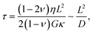 where L is the characteristic length, ν is the Poisson's ratio, G is the modulus, η is the fluid viscosity, κ is the material permeability and D is the effective diffusivity of the fluid, govern the piezoionic recovery time.38,71,72 As a result, longer poroelastic relaxation times result in a slower fluid flow, which in turn leads to longer recovery times.71,72
Charge density, crosslinking density and material density
These are key parameters affecting the charge separation and the resulting output voltage with respect to the flow of charges within a material. Charge density herein refers to the number of mobile ions (or charge) per unit volume; hence, the higher the charge density, the higher the generated output voltage. In contrast, the crosslinking density corresponds to the degree of crosslink points per unit volume, leading to higher resistance to flow within a material. Herein, the generated amplitude of the output voltage at a given applied pressure is approximately proportional to the charge density and inversely proportional to the crosslinking density.44 Dobashi et al.38 attributed a slight attenuation in the amplitude of the output voltage together with longer recovery time to the material density, namely the mass of a material per its unit volume. The latter more effectively leads to changes in the material permeability (ability for fluids to flow through media) and stiffness (modulus).38,39
Novel strategies for structural design towards enhanced piezoionic performance
Recently, several novel strategies for structural design have been proposed for enhancing the performance of piezoionic sensors. These include the introduction of porosity, microphase separation, gradient-like architectures, and the creation of conductive pathways or gates, as follows:
Porosity
Porosity refers to the ratio of the void space inside the total volume in a material, and is generally obtained by means of solvent casting or porogen leaching.60,73 Porosity directly influences the mechanical properties (stiffness) and the permeability of a material, which governs ion diffusion within a piezoionic material (Fig. 5).38,45,60 Consequently, porosity enhances the generated output voltage through two main mechanisms: (1) facilitating easier deformation (reduced stiffness), which increases electromechanical sensitivity, and (2) enhancing the dipole moment, which promotes more efficient charge separation.45,60 Using double-network nanocomposites embedded with an electrolyte (NaCl or K3Fe[(CN)6]/K4Fe[(CN)6]), Li et al.45 demonstrated that smaller pore sizes led to larger mobility differences between the ions, thus allowing for a higher output voltage. Lu et al.60 further demonstrated a three-fold increase in the output voltage (up to 14 mV under 3 N loading) from porous PAAm hydrogels embedded with electrolytes (CaCl2, NaCl or LiCl) compared to their nonporous counterparts together with a higher output voltage with respect to the size of the hydrated ions: Ca2+ (4.12 Å) > Li+ (3.82 Å) > Na+ (3.58 Å) due to higher mobility imbalance (Table 2, entries 11 and 13).
 |
| | Fig. 5 Influence of porosity upon addition of tin selenide nanosheets (SnSe) within polymeric ionic materials with respect to higher generated output voltage. Reproduced with permission from Adv. Funct. Mater.45; © 2023 Wiley-VCH GmbH. | |
Microphase separation
Microphase separation is a phenomenon in which a material organizes into distinct domains.74 This structural arrangement enables relatively high output voltage amplitudes under increased pressure gradients by concentrating stress within the hard phases, while simultaneously exploiting the high ionic mobility of the soft and intermediate phases (Fig. 6).46,60 For example, Lu et al.60 combined microscopic porosity and hydrophilic–hydrophobic phase separation into electrolyte-loaded PAAm networks for pronounced piezoionic performance, generating output voltages as high as 600 mV in response to a medical ultrasound stimulation (Table 2, entry 13). Additionally, Zhu et al.46 introduced EMIm+ TFSI− ionic liquid as a compatibilizer within a microphase-separated system based on ionic plastic crystals and PVDF–HFP for stress concentration and localized charge separation, yielding improved mechanical properties and effective voltage generation up to 90 mV under a 15 kPa loading.
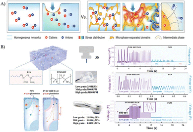 |
| | Fig. 6 Influence of microphase separation within polymeric ionic materials with respect to higher stress localization and enhanced ion separation in comparison to homogeneous networks (A). Reproduced with permission from Adv. Mater.46; © 2024 Wiley-VCH GmbH. Microphase-separated PAAm/PVDF–HFP leads to higher transient voltage generation compared to homogeneous PAAm network with respect to higher ion mobility difference (B). Reproduced with permission from Adv. Mater.60; © 2023 Wiley-VCH GmbH. | |
Gradient-like structures
Gradient-like structures refer to materials with gradually varying properties along their volume (Fig. 7).75 Odent et al.44 developed such polyelectrolyte hydrogels through the copolymerization of AAm with either anionic 3-sulfopropyl acrylate potassium salt (SPA) or cationic [2-(acryloyloxy)ethyl]trimethylammonium chloride (AETA) co-monomers (Table 2, entries 20 and 21). This was achieved using the stereolithography 3D printing of stacked ionic assemblies composed of discrete compartments with distinct ion transport properties. By varying the ion type, charge density, and crosslinking density across these compartments, the output voltage magnitude and polarity of the resulting piezoionic device could be precisely programmed (Fig. 7A). The generated voltage at a given applied pressure was found to be directly proportional to the hydrogel's charge density and inversely proportional to its crosslinking density. Gradient-like structures leverage this principle and allow for the programming of the signal magnitude, enabling controlled amplification or attenuation, through the flow of excess charges from the indented compartment to adjacent compartments with different ion transport properties. As a result, the resulting touch sensors can be integrated onto fingertips, enabling a tactile perception for object recognition applications. Recently, Li et al.61 dramatically enhanced the piezoionic outputs of LiCl-embedded PAAm hydrogels by leveraging the synergistic effects among geometry, modulus (stiffness), and charge gradients (Table 2, entry 14). While the geometry and modulus gradients enhanced the generation of a pressure gradient, the charge gradient increased the mobility difference between the ions, thus leading to a higher output voltage (Fig. 7B). Similarly, Kim et al.54 (Table 2, entry 2) developed bilayer-structured polymeric ionic materials that exhibited a significantly enhanced output signal and faster response time due to the presence of an ion accumulation interface (Fig. 7C). The material further demonstrated the capability to accurately detect both static and dynamic forces, including specific motions, such as bending and vibrations.
 |
| | Fig. 7 Gradient-like structures by means of variations in ion type, charge density, and crosslinking density within the piezoionic device via resin vat exchange during 3D printing (A). Reproduced with permission from Adv. Funct. Mater.44; © 2022 Wiley-VCH GmbH. Multi-gradient structures combining geometry, modulus (stiffness), and charge gradients (B). Reprinted with permission from Nano Energy61; © 2024 Elsevier Ltd. Bilayer polymeric ionic materials with enhanced piezoionic performance with respect to an ion accumulation interface (C). Reprinted with permission from Nano Energy54; © 2024 Elsevier Ltd. | |
Conductive pathways and gates
Conductive pathways and gates can boost the transport of ions within a material, thus improving its piezoionic performance. Dai et al.41 (Table 2, entry 18) introduced oriented polyethylene terephthalate (PET) fibers into LiCl-embedded polyacrylic acid to create conductive pathways that facilitated ion transport along the negatively charged fiber surfaces (Fig. 8). As a result, the output voltage measured parallel to the fiber orientation was significantly higher (27.5 mV vs. 4.3 mV under a 290 kPa load) and exhibited a much faster recovery time (1.5 s vs. 30 s) compared to that in the perpendicular direction. Wang et al.52 (Table 2, entry 12) employed a combination of PAAm, polyvinyl alcohol (PVA), and poly(3,4-ethylenedioxythiophene):poly(styrenesulfonate) (PEDOT:PSS) followed by a simple dry-annealing process to induce a gating effect. Under high pressure, this effect resulted in the accumulation of anions within the indented region. The resulting gate remained open under low deformation, but progressively closed once a threshold force was exceeded. Mechanistically, PEDOT forms crystalline aggregates through π–π stacking, which undergo oxidation, creating a conductive polymer network. This network contains excess positive charges (holes) that electrostatically interact with anions embedded in the hydrogel, thereby reducing their diffusivity.52 In contrast, PSS with its negatively charged sulfonate groups forms ordered nanostructures that act as pathways for embedded cations to move within the hydrogel.52
 |
| | Fig. 8 Conductive pathways by oriented PET fibers within piezoionic materials, providing higher mechanical-to-ionic transduction and resulting voltage generation along the fiber directions. Reprinted with permission from Device41; © 2024 Elsevier Inc. | |
Unveiling operating parameters for piezoionic voltage generation
The operating parameters associated with the sensor configuration and assembly can significantly influence fluid-driven ion transport in piezoionic sensors (Fig. 9). In the following sections, we examine in detail the most critical of these parameters:
 |
| | Fig. 9 Operating parameters affecting the fluid-driven ion transport and voltage generation in piezoionic sensors, including the electrode configuration, the electrode distance and the indentation characteristic (size and speed). | |
Electrode configuration
The two-electrode configuration is the most widely adopted assembly scheme for piezoionic sensors, typically implemented in two modes: coplanar and bending. In the coplanar mode, two electrodes are positioned on the same surface of the material, which is subjected to a compressive stimulus. This drives ion flow and charge transport perpendicular to the indentation. When the reference (ground) electrode is placed beneath the indented region and the working (sensing) electrode on the undeformed region, the resulting voltage polarity can be interpreted based on the ion species that are preferentially displaced: a positive output indicates cation-driven transport, whereas a negative output indicates anion-driven transport (and vice versa).44 By contrast, electrodes are placed on opposite faces of the material in the bending mode, where bending deformation drives ion flow and charge transport parallel to the deformation. Ko et al.54 suggested a bilayer-structured ionic materials for enhancing the output signal and the response time of the sensor, which was constructed after spraying silver nanowires on one side of a film and then half-cutting it; the two films were then assembled face-to-face (Table 2, entry 2).
Electrode composition
Various electrode materials were investigated (Table 2), including metal electrodes such as Cu,40,41,45,60 Au,38,62–64 Ag,54 reduced graphene oxide/carbon nanotubes/silver (RGO/CNT/Ag),55 gold and indium tin oxide glass (Au/ITO glass),59 graphene,56 two-dimensional titanium carbide/silver (MXene/Ag)57 and PEDOT:PSS.52,66 The range of choices in electrode materials is limited by some challenges related to contact with elastic polymer films or hydrogels, and precise current collection. Vapor-phase deposition is primarily employed for sensors operating in compression mode, where a thin conductive layer, typically of noble metals, is directly coated onto polymer films or ionogels, providing excellent conductivity and signal retention.55,62,63 Although noble metals have been widely used as electrodes, their poor mechanical compliance and limited stability under high deformation significantly restrict their effectiveness in bending-mode sensors, especially under large strains.55,62,76,77 In the bending mode, the electrode selection plays a more decisive role in determining the generated voltage, largely due to interfacial challenges between polymeric ionic materials and electrodes.55,56,58,63,64 To overcome these limitations, more flexible and conductive alternatives, such as Ag nanowires,54 graphene,56 MXene,57,59 graphdiyne,65 and PEDOT:PSS42,52,62,66 have been investigated (Table 2, entries 2, 4, 5, 7, 10, 12, 16, 25 and 26). For instance, Lu et al.56 (Table 2, entry 5) developed a trilayer sensor based on a TPU matrix with ILs and MXene electrodes, demonstrating superior electromechanical transduction. The improved performance was attributed to the ultrathin MXene layers with a larger surface area and a higher pore distribution compared to the bulk MXene, yielding output voltages up to 219 mV with excellent cycling stability (98% retention after 10000 cycles). In another study, Lu et al.65 (Table 2, entry 25) reported a trilayer sensor composed of Nafion and graphdiyne electrodes, which facilitated rapid in-plane and out-of-plane ion transport. This design achieved a high output voltage of 116 mV, along with robust stability (94.7% signal retention after 4000 cycles). Similarly, conductive polymers, such as PEDOT:PSS impart stability, high conductivity, and excellent stretchability to polymeric sensors.42,52,57 For example, Ribeiro et al.66 (Table 2, entry 26) fabricated highly stretchable, ionically conductive films coated with flexible PEDOT:PSS electrodes on both sides. At low scan rates, these devices demonstrated volumetric capacitances equivalent to, or even exceeding, those of systems employing ionic liquid electrolytes.
Electrode distance
The electrode spacing strongly influences both the magnitude of the output voltage and recovery time, as it determines the spatio-temporal variation of fluid flow that drives ion transport.39 Under mechanical stimulation, a pressure gradient induces fluid flow, which carries ions and establishes a spatio-temporal electric field within the piezoionic device. Xu et al.39 systematically investigated the effect of the electrode distance using both cationic and anionic single-ion based piezoionic sensors. They demonstrated that increasing the electrode distance led to higher output voltages, but also resulted in longer recovery times (Fig. 10). This behaviour can be explained by the spatial dependence of the electrical potential, described as  where V is the voltage, E is the electrical field, x is the distance between the electrodes and t is time. Consequently, a larger electrode distance results in a higher output voltage. In contrast, the longer the electrode distance, the greater the recovery time as a longer poroelastic relaxation pathway is required for the material to fully recover after deformation.39
 |
| | Fig. 10 Electrode distance effect on both cationically (P-type device) and anionically (N-type device) driven polymeric ionic material together with their respective output voltage as a function of time. Used with permission from Mater. Horiz.39; © 2024 The Royal Society of Chemistry. | |
Indentation size and speed
The indentation size and speed play crucial roles in the generation of a pressure gradient during mechanical loading. Larger indentation sizes result in higher voltage outputs.44 Additionally, Xu et al.39 showed that increasing the indentation speed enhances both the output voltage and reduces the recovery time. However, the voltage response eventually saturates at high indentation speeds, reaching a plateau that reflects an optimal characteristic fluid flow velocity.39 Similarly, the response and recovery times (FWHM) reach a plateau with further increases in the indentation speed. Dai et al.41 consistently reported a comparable trend, observing an increased output voltage with faster indentation speeds.
Applications
Soft wearable electronics
are increasingly being employed for the continuous, non-invasive health monitoring of physiological parameters, offering improved disease diagnosis, progression tracking, and treatment at a relatively low cost.78,79 Such electronics typically consist of a sensing unit combined with a data collection/transmission unit and a power supply.80 Piezoionic systems are self-powered and highly sensitive to mechanical stimuli, making them suitable for telehealth applications. This requires the detection of subtle signals and continuous monitoring over extended periods, such as in the case of cardiac monitoring.65 For example, cardiovascular monitoring, including heart rate and blood pressure monitoring, is crucial for the early detection of heart conditions and diseases.65 In this regard, piezoionic sensors readily allow for the continuous monitoring of patient deterioration.78,79 Lu et al.65 developed a wearable piezoionic sensor capable of distinguishing between systolic and diastolic blood pressures, with measurements consistent with those of commercial devices. Ma et al.42 introduced a dual piezoionic sensor for monitoring both the heart rate and sodium levels in sweat to provide heart parameter monitoring and homeostasis information. While others reported on piezoionic sensors for monitoring heart rate, blood pressure, and human motion,56,57,65 piezoionic sensors have also been used for respiratory and sleep monitoring.56,57,65
Ionic skins, tissue engineering, and biointerfaces
represent a promising avenue for the application of piezoionic sensors with respect to their biomimetic mechanical-to-ionic transduction mechanism, their ability to mimic the production of biological signals and their transmission.6–8 Particularly, complex tactile perception gives rise to the development of ionic-based systems able to mimic some of the functionalities of the skin, well-known as ionic skin.81 Wang et al.52 developed a piezoionic material able to discriminate between innocuous and harmful touch similar to skin receptors. Lu et al.60 developed a piezoionic sensor able to differentiate the spatial localization of pressure. Tissue engineering is an interdisciplinary field that focuses on the restoration of damaged or diseased tissues, and requires biocompatible materials that allow for cell attachment, proliferation, and differentiation. Burattini et al.43 proved the biocompatibility of gelatin-based, single-ion piezoionic systems with respect to cell proliferation and the differentiation of myoblasts, with no adverse effects. Biointerfaces are devices that interact with the neural system to treat a disorder or symptom.80,82 In that regard, Dobashi et al.38 demonstrated that the neuromodulation capabilities of a piezoionic system were able to elicit muscle excitation in mice. Lue et al.41 developed an artificial nerve system using a composite of PET microfiber and PAAc hydrogel, which neuromodulated stimuli in the peripheral sciatic nerve of mice. This proved its capabilities to communicate and be integrated with biological nerve systems. In general, polymeric ionic materials for ionic skin, biointerfaces, neuromodulation or neuroprosthetics must generate an electrical potential of approximately 15–20 mV (threshold potential) to trigger an action potential, enabling communication within the body.6–10,38,41 Focusing on ionic skin applications, piezoionic materials should be able to mimic the complex somatosensory system of the skin. Specifically, this includes mimicking the four low-threshold mechanoreceptors in the skin: Merkel cells, Meissner corpuscles, Pacinian corpuscles, and Ruffini endings. Firstly, the sensitivity of polymeric ionic materials to deformation should match the sensitivity of these mechanoreceptors in the skin, which can detect forces as subtle as 0.5 mN.6–8 As such, Fig. 11 illustrates the maximum output potential against the frequency response time for selected piezoionic sensors. Most current piezoionic systems exhibit frequency responses similar to those of Merkel cells and Meissner corpuscles, with maximum potentials exceeding 15 mV, rendering them able to trigger an action potential. Thus, they could be used for neuromodulation, ionic skin or biointerfaces. Nonetheless, piezoionic systems with a frequency response similar to that of Pacinian corpuscles are still missing. The development of piezoionic systems capable of mimicking each type of mechanoreceptor is a step toward producing a more complex ionic skin that is able to fully mimic the intricate touch perception of the skin.
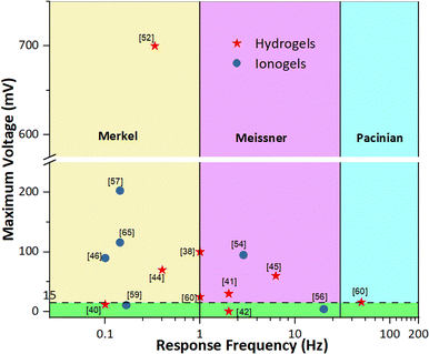 |
| | Fig. 11 Maximum voltage with respect to frequency response times of common polymeric ionic materials. Range of action potentials (green region), frequency range of Merkel cells (yellow region), frequency range of Meissner corpuscles (purple region) and frequency range of Pacinian corpuscles (teal region) are identified. | |
Energy harvesting
appears as a promising application for piezoionics owing to their ability to convert mechanical energy into electrical energy.48 Yet, piezoionic devices are less efficient than common energy harvesters with respect to their production of low output voltage in the few-hundred-millivolt range, with only a peak power per volume comparable to that of common harvesters.38,52,60 While piezoelectric devices produce power densities in the range of 0.4–30 µW cm−3,3,83 piezoionics are reported with power densities in the range of 0.85–1.3 µW cm−3.38,52,60 Despite these limitations, piezoionic systems offer substantial potential for further improvement and are competitive with some low-performance piezoelectric harvesters. Nevertheless, mechanical-to-ionic transduction is relatively novel and has not been extensively studied, especially for energy harvesting, suggesting a promising avenue for enhancing the capabilities of piezoionic systems as next-generation energy harvesters.
Limitations for real-sensing devices persist as several challenges must still be overcome before piezoionic transducers can be translated into practical and reliable sensing technologies. These constraints, such as a slower response, impact the device performance, depending on the specific application. In this regard, overcoming these limitations is the cornerstone for achieving functional integration and ensuring long-term operational stability in real-world sensing environments. The strategies that have previously been developed for mitigating these limitations in the realm of soft sensor technologies afford promising avenues for the future adaptation of piezoionic devices, as described hereafter.84,85 A primary limitation stems from the intrinsic water-dependent behaviour of piezoionic transducers, which can be mitigated through encapsulation strategies for minimizing water loss and enhancing environmental stability.38 However, the encapsulation must be judiciously designed to preserve mechanical compliance, maintain ionic conductivity, and ensure long-term durability. This consideration is particularly critical for ionic-skin applications, where the mechanical properties of the device must closely match those of biological tissues. An alternative approach consists of developing water-retaining materials86,87 that demonstrate remarkable stability under extreme temperature variations, thereby enabling reliable device performance through diverse environmental conditions. Aside from encapsulation and the development of water-retaining materials, deep eutectic solvent-based systems have emerged as a promising alternative for ionic skins, offering superior properties than regular ionogels.88 The implementation of all-solid-state systems represents another promising approach, offering liquid-free materials with moderate ionic conductivity, robust mechanical properties, and high thermal stability. As demonstrated by Ribeiro et al.,66 who reported a PIL-based piezoionic sensor, such materials exhibit exceptional compatibility for achieving stable piezoionic performance. The absence of liquids (e.g., water) can mitigate dehydration and leakage, substantially extending a device's operational lifetime. Of particular relevance to ionic skin, tissue engineering and biointerface applications are stringent biocompatibility requirements, which can severely constrain the selection of suitable materials that can be safely interfaced with tissues.80,84 While piezoionic transducers possess tissue-like mechanical softness and ionic transport characteristics comparable to those of biological tissues, their stable operation under physiological conditions remains challenging due to dehydration, leaching, and compositional instability. Achieving robust adhesion and seamless integration with biological systems without perturbing native physiological functions also constitutes a major frontier for these applications.49,84 Beyond hydration stability and biocompatibility, ensuring durability and long-term operational reliability certainly represent other crucial design objectives.84 Soft electromechanical sensors are subjected to repeated mechanical and environmental stresses, underscoring the need for resilient, self-healing materials that support the realization of stable, long-lasting sensing platforms. For instance, the incorporation of reversible bonding interactions (similarly to supramolecular materials) can substantially enhance durability, improve mechanical performance, and extend the overall device lifespan.89 For example, Hu et al.90 developed a supramolecular ionic gel with self-healing capability for soft sensor applications based on a deep eutectic solvent, while Kim et al.54 reported a piezoionic sensor (PVDF swollen in EMIM-TFSI) integrating a similar autonomous self-healing functionality. Both the response and recovery times are key determinants of the performance of piezoionic devices. They are influenced by mechanical hysteresis stemming from viscoelastic energy dissipation91 and ionic hysteresis arising from the temporal mismatch between pressure-driven ion transport and diffusion-mediated re-equilibration.38,49 Although piezoionic transducers typically exhibit response and recovery times on the order of seconds and are suitable for soft wearable electronics, mechanical hysteresis continues to pose a significant challenge. In particular, low mechanical hysteresis is an imperative characteristic for soft sensors, facilitating the swift recovery of deformed materials, swift electrical signal response, and the maintenance of signal cyclic stability.92 Among the strategies for reducing mechanical hysteresis, supramolecular architectures can distribute stress uniformly under repeated deformation, minimizing energy dissipation.91,93 For example, Sun et al.93 reported low-hysteresis supramolecular ionogels achieving ca. 11.7% hysteresis at 400% strain. Other strategies for reducing mechanical hysteresis include densely entangled polymer networks, phase separation, or the incorporation of controlled microstructures, such as microcracks and microchannels, which guide deformation and facilitate recovery of the original shape.85,91 To date, piezoionic devices for energy harvesting and biointerfaces applications require rapid response and recovery times, making ionic hysteresis a critical challenge. Conductive pathways, as demonstrated by Dai et al.,49 endow faster response and recovery times. For biointerfaces, particularly in neuromodulation, the stimulation frequencies of the device are crucial for achieving therapeutic efficacy (as determined by the response and recovery times).94 For energy harvesters, slow mechanical-to-ionic transduction limits operational frequency, restricting energy conversion efficiency compared with conventional electromechanical sensors. Therefore, structural design strategies including gradient-like structures, controlled porosity, and microphase separation can enhance output voltages and efficiency. Careful attention to data acquisition, calibration, and signal processing is essential as piezoionic transducers are sensitive to external noise, including capacitive and triboelectric interferences.38 Ultimately, the convergence of these advances will enable the development of piezoionic devices that are stable, reproducible, and fully compatible with the mechanical and operational demands of next-generation applications.
Conclusions
Polymeric ionic materials undoubtedly represent the base for the next-generation of iono–electromechanical sensors with respect to their biomimetic mechanical-to-ionic transduction mechanism, their ability to mimic the production of biological signals and their transmission. Overall, a fluid pressure gradient is created under mechanical stimulation which drives fluid flow within the matrix. As a result, a transient separation between cations and anions takes place due to their different mobilities and interactions, breaking electrical neutrality and generating a transient voltage. Although the working principle of mechanical-to-ionic transduction in polymeric ionic materials is not yet fully understood, a foundational framework has been established that outlines the underlying transduction mechanism and the key parameters governing voltage generation.
We classified these parameters into two groups based on their principle of action: structural parameters primarily relate to the design of the polymer matrix, while operational parameters concern sensor assembly and practical operation. Among the structural parameters, the most critical ones are the type of polymer matrix, the nature and mobility of the ionic species, the conduction mechanism (single-ion vs. ion-pair), material dimensions (including thickness), charge density, crosslinking density, porosity, microphase separation, as well as the presence of gradient-like structures or conductive pathways. The performance of piezoionic sensors is strongly governed by the type of polymer matrix and the mobility of the incorporated ionic species. While hydrogel- and ionogel-based systems offer exceptionally high voltage outputs due to the presence of liquid ion transporters, their long-term stability is limited by evaporation, leakage, or leaching. In contrast, solid-state polyelectrolyte systems eliminate these drawbacks, providing superior safety, durability, and suitability for skin- and health-monitoring applications. Importantly, single-ion conducting solid-state matrices, particularly those based on polyelectrolytes and poly(ionic liquid)s, are the most promising direction, as they enable stable ion-gradient formation, reduced voltage decay, and competitive output voltages (up to 190 mV). Ion mobility is governed by ion diffusion within the matrix, which is influenced by factors, such as ionic charge, size, concentration, and electrophoretic mobility. In single-ion conducting systems, optimal performance is achieved when the mobile ions are small, exhibit high charge delocalization, and show minimal coordination with the polymer matrix. By contrast, in ion-pair conducting systems, performance can be enhanced by selectively reducing the mobility of one ionic species, thereby facilitating the formation of stable charge gradients.
Thinner films are more favorable, as they enable higher voltage generation and faster response due to narrower force distribution and shorter poroelastic relaxation times. A high charge density is critical since a greater number of mobile ions per unit volume directly amplifies the generated output voltage. In contrast, the crosslinking density should be kept relatively low, because excessive crosslinking restricts fluid and ion transport, leading to a reduced voltage output and a slower response. A moderate degree may still be required to maintain mechanical robustness. Lower material density is preferable, as high density increases stiffness and reduces permeability, which slows fluid flow and extends recovery times. Overall, the most promising polymer matrices for piezoionic sensors are therefore thin, lightweight, and moderately crosslinked systems with a high charge density. Such a combination maximizes ion transport efficiency, enhances voltage generation, and ensures fast response and recovery times under mechanical loading.
When speaking about additional structural design, the highest-performing piezoionic polymer matrices based on their ion-pair mobility should combine small, well-distributed porosity and microphase-separated domains. An optimal porous structure is beneficial, as it reduces stiffness (enhancing electromechanical sensitivity) and increases charge separation efficiency. Smaller, well-distributed pores are especially effective, since they maximize ion mobility differences and improve voltage generation. The coexistence of hard and soft domains allows stress concentration in rigid phases, while enabling rapid ion transport in soft regions. For both single-ion and ion-paired systems, the creation of gradient-like architectures and the incorporation of directed conductive pathways and gating mechanisms are of great importance. By designing gradients for the ion type, charge density, stiffness, or geometry, the system can achieve controlled amplification, faster responses, and multifunctional sensing capabilities, such as discrimination between static and dynamic forces.
As mechanical-to-ionic transduction is relatively new and not yet extensively studied, there is currently no standardized approach for assembling and testing piezoionic sensors. Different authors employ diverse evaluation methods, making direct comparison of results challenging. While most studies report the generated voltage under varying mechanical loads, data on the relaxation time (how quickly the sensor can be reused without loss of sensitivity) and response time (how rapidly it responds to an applied load) are generally lacking. Despite these limitations, this review not only provides guidelines for designing efficient piezoionic devices with an enhanced performance, but also outlines optimal strategies for sensor assembly and offers fundamental insights into the underlying piezoionic mechanism. Ultimately, careful matrix design via the optimization of ionic mobility, crosslinking density, and electrode interfaces will be essential for advancing solid-state piezoionic sensors as the leading platform for future applications.
Author contributions
Conceptualization: J. A. G., C. P., J.-M. R., J. O.; investigation: J. A. G., V. S.; supervision: J.-M. R., J. O.; writing – original draft: J. A. G., J. O.; writing – review and editing: C. P., A. S., J.-M. R., J. O.; and funding acquisition: A. S., J.-M. R., J. O. All authors have read and agreed to the published version of the manuscript.
Conflicts of interest
There are no conflicts to declare.
Data availability
No primary research results, software or code have been included and no new data were generated or analysed as part of this review.
Acknowledgements
We gratefully acknowledge support from the Belgian Federal Government Office of Science Policy (SSTC-PAI 6/27) as well as both Wallonia and the European Commission “FSE and FEDER”. The authors also acknowledge the PDR project “INFINITE” supported by the Fonds de la Recherche Scientifique (F.R.S.-FNRS) and the Luxembourg National Research Fund (FNR) (agreement number INTER/FNRS/21/16555380/INFINITE). J.-M.R. is an FNRS Research Director and a WEL-T Researcher. Some figures in this work were created with https://biorender.com/.
Notes and references
- R. Cao, H. Tian, Y. Tian and X. Fu, Adv. Sci., 2024, 11(11), 2302327 CrossRef PubMed.
- S. Liu, S. Wang, L. Zou and W. Xiong, Cell. Mol. Life Sci., 2021, 78, 5083–5094 CrossRef CAS PubMed.
- S. Maksimovic, M. Nakatani, Y. Baba, A. M. Nelson, K. L. Marshall, S. A. Wellnitz, P. Firozi, S.-H. Woo, S. Ranade, A. Patapoutian and E. A. Lumpkin, Nature, 2014, 509, 617–621 CrossRef CAS PubMed.
- M. J. Caterina, J. Clin. Invest., 2021, 131, e156587I CrossRef.
- D. Julius, Annu. Rev. Cell Dev. Biol., 2013, 29, 355–384 Search PubMed.
- A. Yamada, J. Ling, A. I. Yamada, H. Furue and J. G. Gu, Neuron, 2024, 112(8), 1286–1301 CrossRef CAS PubMed.
- L. Wang, L. Ma, J. Yang and J. Wu, Cyborg Bionic Syst., 2021, 9843259 Search PubMed.
-
A. Roe, R. Friedman and L. Chen, in Handbook of Neurochemistry and Molecular Neurobiology: Sensory Neurochemistry, ed. D. A. Johnson and A. Lajtha, Springer Science & Business Media, 2007, pp. 1–16 Search PubMed.
- K. Xiao, C. Wan, L. Jiang, X. Chen and M. Antonietti, Adv. Mater., 2020, 32(31), 2000218 Search PubMed.
- G. Sun, P. Wang, Y. Jiang, H. Sun, C. Meng and S. Guo, Soft Sci., 2022, 2, 17 CrossRef CAS.
- K. H. Ha, H. Huh, Z. Li and N. Lu, ACS Nano, 2022, 16(3), 3442–3448 CrossRef CAS PubMed.
- J. Hu, G. Dun, X. Geng, J. Chen, X. Wu and T.-L. Ren, Nanoscale Adv., 2023, 12, 3131–3145 Search PubMed.
- Z. Zhang, SHS Web Conf., 2023, 157, 01026 CrossRef.
- X. Zhang, J. Xu, Z. Chen, G. Zhu, A. Wei and D. Chen, J. Alloys Compd., 2024, 1007, 176408 CrossRef CAS.
- J. Chen, T. Song, X. Wang, Y. Zhou, T. Wang, X. Zhang and W. Han, Nano Energy, 2024, 131, 110285 Search PubMed.
- L. Wang, H. Ning, S. Chen, Y. Huang, S. Chen, L. Wang and J. Peng, Appl. Mater. Today, 2024, 41, 102474 CrossRef.
- L. Liu, Y. Zhang, L. Tan, Y. Deng, X. Zheng, K. Tang and Y. Pei, Chem. Eng. J., 2024, 499, 155975 Search PubMed.
- Q. Li, Z. Zhang, L. Xu, X. Wang and Z. Li, Sens. Actuators, A, 2024, 378, 115849 Search PubMed.
- J. Wang, Y. Zhong, S. Dai, H. Zhu, L. Wu, F. Gu and J. Ding, ACS Appl. Nano Mater., 2022, 5(9), 13227–13235 CrossRef CAS.
- M. Cheng, Y. Yuan, Q. Li, C. Chen, J. Chen, K. Tian and H. Deng, J. Mater. Sci. Technol., 2025, 217, 60–69 CrossRef CAS.
- V. Amoli, J. S. Kim, E. Jee, Y. S. Chung, S. Y. Kim, J. Koo and D. H. Kim, Nat. Commun., 2019, 10(1), 4019 Search PubMed.
- J. S. Kim, H. Choi, H. J. Hwang, D. Choi and D. H. Kim, Macromol. Biosci., 2020, 20(11), 2000147 CrossRef CAS PubMed.
- H. Huang, X. Ran, S. Wan, Y. Wang and H. Bi, Nanoscale, 2024, 16(38), 17926–17933 Search PubMed.
- C. Liu, M. H. Uddin and K. Zhang, Sens. Actuators, A, 2024, 374, 115519 CrossRef CAS.
- Y. Zhou, L. Zhao, Q. Jia, T. Wang, P. Sun, F. Liu and G. Lu, ACS Appl. Mater. Interfaces, 2022, 14(49), 55109–55118 Search PubMed.
- N. Bai, L. Wang, Y. Xue, Y. Wang, X. Hou, G. Li and C. F. Guo, ACS Nano, 2022, 16(3), 4338–4347 CrossRef CAS PubMed.
- P. Lu, L. Wang, P. Zhu, J. Huang, Y. Wang, N. Bai and C. F. Guo, Sci. Bull., 2021, 66(11), 1091–1100 CrossRef.
- M. Zhong, L. Zhang, X. Liu, Y. Zhou, M. Zhang, Y. Wang and D. Wei, Chem. Eng. J., 2021, 412, 128649 CrossRef CAS.
- J. Luo, L. Zhang, T. Wu, H. Song and C. Tang, Extreme Mech. Lett., 2021, 48, 101279 CrossRef.
- L. Zhen, M. Cui, X. Bai, J. Jiang, X. Ma, M. Wang and B. Yang, Nano Energy, 2024, 131, 110188 CrossRef CAS.
- Y. Chen, C. Qin, Q. Sun and M. Wang, Sens. Actuators, A, 2024, 379, 115970 CrossRef CAS.
- Y. Zhang, C. Liu, B. Jia, D. Ma, X. Tian, Y. Cui and Y. Deng, npj Flexible Electron., 2024, 8(1), 23 Search PubMed.
- X. Sui, Q. Mu, J. Li, B. Zhao, H. Gu, H. Yu and D. Hu, Biosensors, 2024, 14(10), 508 Search PubMed.
- S. Zhao, C. Chen, Z. Wang, C. Pan and C. Yang, InfoMat, 2024, e12552 Search PubMed.
- J. Xu, H. Li, Y. Yin, X. Li, J. Cao, H. Feng and G. Zhu, Flexible Electron., 2024, 6(1), 62 Search PubMed.
- C. Wan, K. Xiao, A. Angelin, M. Antonietti and X. Chen, Adv. Intell. Syst., 2019, 1(7), 1900073 CrossRef.
- S. Mirza, Y. Dobashi, E. Glitz, M. Farajollahi, S. Mirabbasi, S. Naficy and J. D. Madden, Electroactive Polym. Actuators Devices (EAPAD), 2015, 9430, 505–513 Search PubMed.
- Y. Dobashi, D. Yao, Y. Petel, T. N. Nguyen, M. S. Sarwar, Y. Thabet and J. D. Madden, Science, 2022, 376(6592), 502–507 Search PubMed.
- J. Xu, Q. Li and D. Ho, Mater. Horiz., 2024, 11(22), 5709–5721 Search PubMed.
- Y. Dobashi, G. Allegretto, M. S. Sarwar, E. Cretu and J. D. Madden, MRS Adv., 2016, 1(1), 63–68 CrossRef CAS.
- J. Dai, Y. Xue, X. Chen, Z. Cao, L. Wang, J. Zhang and K. Xiao, Device, 2024, 2(7), 100436 CrossRef.
- B. Ma, K. Huang, G. Chen, Y. Tian, N. Jiang, C. Zhao and H. Liu, Soft Sci., 2024, 4, 8 CAS.
- M. Burattini, R. Lippens, N. Baleine, M. Gerard, J. Van Meerssche, C. Geeroms and L. Thorrez, Macromol. Biosci., 2023, 23(7), 2300019 CrossRef CAS.
- J. Odent, N. Baleine, V. Biard, Y. Dobashi, C. Vancaeyzeele, G. T. Nguyen and J. M. Raquez, Adv. Funct. Mater., 2023, 33(3), 2210485 CrossRef CAS.
- F. Li, X. Cai, G. Liu, H. Xu and W. Chen, Adv. Funct. Mater., 2023, 33(32), 2300701 CrossRef CAS.
- W. Zhu, B. Wu, Z. Lei and P. Wu, Adv. Mater., 2024, 36(18), 2313127 CrossRef CAS.
- D. Ho, ChemElectroChem, 2024, 11(3), e202300268 CrossRef CAS.
- K. Chen and D. Ho, Aggregate, 2024, 5(1), e425 CrossRef CAS.
- P. G. De Gennes, K. Okumura, M. Shahinpoor and K. Kim, J, Europhys. Lett., 2000, 50(4), 513 CrossRef CAS.
- Z. Song, X. Cao and H. Huang, Phys. Rev. E, 2018, 97(1), 012411 CrossRef CAS.
- Z. Song, X. Cao and H. Huang, Phys. Rev. E, 2018, 98(3), 032404 CrossRef CAS.
- S. Wang, T. Yang, D. Zhang, Q. Hua and Y. Zhao, Adv. Mater., 2024, 36(36), 2405391 CrossRef CAS PubMed.
- M. Kilic, M. Bazant and A. Ajdari, Phys. Rev. E: Stat. Phys., Plasmas, Fluids, Relat. Interdiscip. Top., 2007, 75, 021503 CrossRef.
- Y. R. Kim, G. Lim, H. Cho, J. Kim, J. Kim, J. Yeom and H. Ko, Nano Energy, 2024, 127, 109749 Search PubMed.
- J. Zhao, S. Han, Y. Yang, R. Fu, Y. Ming, C. Lu and W. Chen, ACS Nano, 2017, 11(9), 8590–8599 Search PubMed.
- Y. Liu, Y. Hu, J. Zhao, G. Wu, X. Tao and W. Chen, Small, 2016, 12(36), 5074–5080 Search PubMed.
- C. Lu, X. Yu, Y. Chen, X. Chen and X. Zhang, Chem. Eng. J., 2023, 463, 142523 Search PubMed.
- J. I. Lee, H. Choi, S. H. Kong, S. Park, D. Park, J. S. Kim and M. S. Kang, Adv. Mater., 2021, 33(29), 2100321 CrossRef CAS PubMed.
- L. Li, J. Pan, L. Chang, Z. Liu, G. Wu and Y. Hu, Chem. Eng. J., 2024, 482, 148988 CrossRef CAS.
- X. Lu, Y. Chen, Y. Zhang, J. Cheng, K. Teng, Y. Chen and Q. An, Adv. Mater., 2024, 36(2), 2307875 CrossRef CAS PubMed.
- L. Li, Y. Shao, L. Jia, Z. H. Guo, Z. Li, Z. L. Wang and X. Pu, Nano Energy, 2025, 133, 110477 CrossRef CAS.
- A. Adjaoud, G. T. Nguyen, L. Chikh, S. Péralta, L. Trouillet-Fonti, N. Uguen and C. Plesse, Smart Mater. Struct., 2021, 30(10), 105027 CrossRef CAS.
- Y. Ming, Y. Yang, R. P. Fu, C. Lu, L. Zhao, Y. M. Hu and W. Chen, Adv. Mater. Technol., 2018, 3(12), 1800257 CrossRef.
- C. Lu, X. Chen and X. Zhang, ACS Sens., 2023, 8(4), 1624–1629 CrossRef CAS.
- C. Lu and X. Zhang, Carbon, 2024, 222, 118956 Search PubMed.
- F. Braz Ribeiro, B. Ni, G. T. Nguyen, E. Cattan, A. S. Shaplov, F. Vidal and C. Plesse, Adv. Mater. Interfaces, 2023, 10(10), 2202381 CrossRef CAS.
- A. S. Shaplov, R. Marcilla and D. Mecerreyes, Electrochim. Acta, 2015, 175, 18–34 CrossRef CAS.
- C. Shan, Y. Wang, M. Liang, K. Lu, C. Xiong, W. Hu and B. Liu, Energy Storage Mater., 2023, 63, 102955 Search PubMed.
- Z. Zhu, L. Chang, T. Horiuchi, K. Takagi, A. Aabloo and K. Asaka, J. Appl. Phys., 2016, 119(12), 124901 CrossRef.
- A. Gray-Weale, Aust. J. Chem., 2009, 62(4), 288–297 CrossRef CAS.
- Y. Hu and Z. Suo, Acta Mech. Solida Sin., 2012, 25(5), 441–458 CrossRef.
- Q. M. Wang, A. C. Mohan, M. L. Oyen and X. H. Zhao, Acta Mech. Sin., 2014, 30, 20–27 CrossRef CAS.
- J. Grenier, H. Duval, F. Barou, P. Lv, B. David and D. Letourneur, Acta Biomater., 2019, 94, 195–203 Search PubMed.
- Y. Matsushita, Encycl. Polym. Nanomater., 2014, 1–6 Search PubMed.
- H. Wang, Y. Xia, Z. Zhang and Z. Xie, J. Mater. Chem. B, 2023, 11(37), 8883–8896 RSC.
- G. Liu, Y. Deng, B. Ni, G. T. Nguyen, C. Vancaeyzeele, A. Brûlet and M. H. Li, Small, 2024, 20(12), 2307565 Search PubMed.
- F. Hu, Y. Xue, J. Xu and B. Lu, Front. Rob. AI, 2019, 6, 114 CrossRef PubMed.
- H. C. Ates, P. Q. Nguyen, L. Gonzalez-Macia, E. Morales-Narváez, F. Güder, J. J. Collins and C. Dincer, Nat. Rev. Mater., 2022, 7(11), 887–907 CrossRef.
- J. V. Vaghasiya, C. C. Mayorga-Martinez and M. Pumera, npj Flexible Electron., 2023, 7(1), 26 CrossRef.
- H. J. Yoon, D. M. Lee, Y. J. Kim, S. Jeon, J. H. Jung, S. S. Kwak and S. W. Kim, Adv. Funct. Mater., 2021, 31(23), 2100649 CrossRef CAS.
- T. Denison and M. J. Morrell, Neurology, 2022, 98(2), 65–72 CrossRef.
- A. Gupta, N. Vardalakis and F. B. Wagner, Commun. Biol., 2023, 6(1), 14 CrossRef.
- N. Sezer and M. Koç, Nano Energy, 2021, 80, 105567 CrossRef CAS.
- Z. Lei, W. Xu and G. Zhang, Smart Med., 2023, 2(1), e20220026 CrossRef.
- R. Papani, Y. Li and S. Wang, Wiley Interdiscip. Rev.: Nanomed. Nanobiotechnol., 2024, 16(3), e1961 Search PubMed.
- Z. Shen, J. Ma, Y. Cai, S. Li, D. Ruan, S. Dai and Z. Jia, Cell Rep. Phys. Sci., 2023, 4(12), 101741 Search PubMed.
- J. Wen, J. Tang, H. Ning, N. Hu, Y. Zhu, Y. Gong and T. Huang, Adv. Funct. Mater., 2021, 31(21), 2011176 CrossRef CAS.
- B. B. Hansen, S. Spittle, B. Chen, D. Poe, Y. Zhang, J. M. Klein and J. R. Sangoro, Chem. Rev., 2020, 121(3), 1232–1285 CrossRef PubMed.
- M. Khatib, O. Zohar and H. Haick, Adv. Mater., 2021, 33(11), 2004190 CrossRef CAS.
- J. Hu, X. Yao, T. Li, X. Li, W. Wei and J. Liu, ACS Appl. Polym. Mater., 2023, 5(11), 9650–9658 CrossRef CAS.
- F. X. Liu, X. Jing, J. Yang, H. Y. Mi, F. Y. Feng and Y. J. Liu, Nano Today, 2025, 61, 102601 CrossRef.
- Z. Zhang, L. Qian, J. Cheng, C. Ma and G. Zhang, Adv. Funct. Mater., 2024, 34(37), 2402115 CrossRef CAS.
- B. Sun, K. Liu, B. Wu, S. Sun and P. Wu, Adv. Mater., 2024, 36(44), 2408826 CrossRef CAS Low hysteresis.
- I. Ezeokafor, A. Upadhya and S. Shetty, Front. Neurosci., 2021, 15, 671767 CrossRef PubMed.
|
| This journal is © The Royal Society of Chemistry 2026 |
Click here to see how this site uses Cookies. View our privacy policy here. 
 Open Access Article
 This Open Access Article is licensed under a Creative Commons Attribution-Non Commercial 3.0 Unported Licence
 a,
Cédric
Plesse
a,
Cédric
Plesse


 where L is the characteristic length, ν is the Poisson's ratio, G is the modulus, η is the fluid viscosity, κ is the material permeability and D is the effective diffusivity of the fluid, govern the piezoionic recovery time.38,71,72 As a result, longer poroelastic relaxation times result in a slower fluid flow, which in turn leads to longer recovery times.71,72


 where V is the voltage, E is the electrical field, x is the distance between the electrodes and t is time. Consequently, a larger electrode distance results in a higher output voltage. In contrast, the longer the electrode distance, the greater the recovery time as a longer poroelastic relaxation pathway is required for the material to fully recover after deformation.39

