
 Open Access Article
 This Open Access Article is licensed under a Creative Commons Attribution-Non Commercial 3.0 Unported Licence
Detection, identification, and quantification of polymer additives: a review of techniques, approaches, challenges, and a possible roadmap in analysis
Tanmay
Rahman
 a,
Daniel
Meadows
a,
Ke
Zhan
b,
Harrish Kumar
Senthil Kumar
a,
Marshall
Smith
c,
Virginia A.
Davis
a,
Bryan S.
Beckingham
a,
Yucheng
Peng
b and
Edward
Davis
*c
a,
Daniel
Meadows
a,
Ke
Zhan
b,
Harrish Kumar
Senthil Kumar
a,
Marshall
Smith
c,
Virginia A.
Davis
a,
Bryan S.
Beckingham
a,
Yucheng
Peng
b and
Edward
Davis
*c
aDepartment of Chemical Engineering, Auburn University, Auburn, AL 36849, USA
bCollege of Forestry, Wildlife and Environment, Auburn University, Auburn, AL 36849, USA
cDepartment of Mechanical Engineering, Auburn University, Auburn, AL 36849, USA. E-mail: ewd0001@auburn.edu
First published on 21st January 2026
Abstract
The type and concentration of additives in polymer systems play a crucial role in determining the physical, mechanical, and chemical properties of these materials, as well as influencing their processing and performance in end-use applications. However, polymer additive detection, identification, and quantification are challenging due to the very low concentrations used and the poor solubility of some additives in solvents required for testing. In addition, polymer degradation products can interact with the additives during testing. To address these challenges, various techniques have been developed. Each method offers unique advantages and challenges, including sensitivity, specificity, and limitations in the polymer systems to which it is applicable. Understanding the advantages and limitations of these methods is essential for selecting the appropriate technique for the polymer additive system under analysis. This article reviews the primary methods used for polymer additive detection, identification, and quantification, including Fourier transform infrared (FTIR) spectroscopy, Raman spectroscopy, nuclear magnetic resonance (NMR) spectroscopy, gas chromatography (GC), mass spectrometry (MS), high performance liquid chromatography (HPLC), carbon/hydrogen/nitrogen/sulfur (CHNS) analysis, inductively coupled plasma (ICP) analysis, energy dispersive X-ray spectroscopy (EDS), thermogravimetric analysis (TGA), differential scanning calorimetry (DSC), and X-ray diffraction (XRD). This review critically examines the challenges of qualitatively and quantitatively evaluating additive content using these methods, while highlighting their strengths and limitations, and how combinations of techniques can be used synergistically to enhance capabilities. This review aims to provide foundational insights and a potential roadmap for researchers and engineers who are beginning to explore polymer additives.
 Tanmay Rahman | Tanmay Rahman is a Ph.D. researcher in the Department of Chemical Engineering at Auburn University. His research focuses on multilayer food packaging recycling, developing strategies to recover and repurpose complex polymer structures, and investigating the processability of recycled polymers for circular economy applications. In addition, he explores the structure–property–process relationships of bio-derived nanomaterials, such as cellulose nanocrystals (CNC), for mass sensing applications to advance towards sustainability. |
 Daniel Meadows | Daniel Meadows is currently a research engineer at ReLogic Research. He obtained both his Ph.D. and B.S. in chemical engineering from Auburn University. During his Ph.D. work, he focused on polymer engineering leveraging analytical laboratory techniques like FTIR, Raman, rheology, and thermal analysis. |
 Ke Zhan | Ke Zhan received his PhD in Forestry from Auburn University in 2025 and his master's degree in Wood Science and Technology from Southwest Forestry University in 2021. His research focuses on utilizing forest-based feedstocks to develop sustainable polymer composites, aiming to address critical environmental challenges. |
 Harrish Kumar Senthil Kumar | Harrish Kumar Senthil Kumar is a 4th-year PhD candidate in the Chemical engineering department at Auburn University. His work specializes in the recycling/recovery and characterization of multilayered packaging plastics. In addition, he also works on the innovative use of 3D printing technologies to create reactive porous media, a key component in studying subsurface systems. Through this interdisciplinary approach, he aims to enhance the understanding of material behavior in both environmental and sustainable engineering contexts. |
 Marshall Smith | Marshall Smith is currently a PhD student in Dr Edward Davis's lab at Auburn University in the Materials Engineering Program. He is researching the dissolution of multilayer polymer structures and thermal degradation characteristics, mixed with gas chromatography and mass spectrometry. His research interests are polymer composites, 3D printing, and space-based materials. |
 Edward Davis | Edward W. Davis (Ph.D., University of Akron) is an Associate Professor of Materials Engineering at Auburn University. Following an 11-year career in the plastics industry at Shell Chemicals and EVALCA, his research now focuses on the environmental and biological applications of polymeric nanomaterials and polymer recycling. Dr Davis is also a dedicated STEM education researcher, specifically investigating how integrating global societal challenges into the curriculum can motivate engineering interest among high school students. His work bridges advanced polymer science with pedagogical strategies to promote engineering as a viable and impactful career. |
1. Introduction
Polymer additives are indispensable components of plastic formulations, serving a critical role throughout the material lifecycle. They are essential for preserving material integrity under the thermal and mechanical stresses of melt processing, modulating functional properties such as elasticity, mechanical strength, and barrier resistance to meet specific application requirements, and extending operational lifespan through long-term environmental stabilization. By enabling this precise tuning of chemical and physical characteristics, additives have transformed polymers from simple commodities into highly engineered materials, driving the continuous advancement and diversification of plastic technologies.1–3 The type and concentration of additives incorporated in polymer materials vary with application area, e.g., automotive, smart devices, healthcare, energy storage, and food packaging. Additives encompass a diverse range of chemical structures, each serving specific functions. However, they can generally be categorized into three types: those that preserve the inherent properties of polymers during polymer synthesis and processing, those that prolong the lifespan of the plastic application, and those that modify the polymer's material properties, enabling use in some applications.4 The first category includes additives that facilitate shaping of plastics and protect them from degradation caused by heat, oxidation, mechanical stress, or chemical exposure during processing. These additives help maintain the integrity of the polymer chains and preserve molecular weight. Typical examples in this group include plasticizers (PL), antioxidants (AO), heat stabilizers (HS), processing aids (PA), and slip additives (SA). Another category of additives is those that prolong the service life of plastic products during end-use applications. These include UV/light stabilizers (UVS), antimicrobials, and some antioxidants (AO). Such additives help preserve a polymer's molecular structure and maintain its performance over time, especially under challenging conditions like outdoor exposure, UV radiation, microbial attack, and electrostatic discharge. The third category of additives includes nucleating agents, clarifiers, surface modifiers, impact modifiers, pigments, optical brighteners, fillers, phosphorus-based modifiers, boron-based electrolytes, flame retardants (FR), and antifogging or antistatic agents. These additives modify the mechanical, thermal, electrical, and surface properties of the polymer, enabling its use in applications requiring a specific property set, for example, transparent PP jars or flame-retardant clothing. In most cases, these additives improve polymer properties without altering their molecular weight or backbone structure. However, chain extenders, cross-linking, and branching agents react with the polymer chains, leading to significant changes in the polymer's molecular structure and mechanical behavior.4–6Another broad classification of polymer additives is whether they are organic or inorganic. Organic additives are carbon-based compounds, while inorganic additives are composed of mineral or metallic elements. The choice between organic and inorganic additives depends on the intended application, required performance, and environmental or regulatory considerations. The following paragraphs review several common additive categories, their chemical structures, and functions.
Among the many additive categories, plasticizers (PL) are one of the most widely used, playing a role in tailoring polymer flexibility and processability. They work by increasing the free volume of the system, thus decreasing characteristic relaxation times of the material.7 PL are usually grouped into two different classes: phthalate esters and non-phthalate esters (Table 1). Around 85% of all PLs used worldwide are phthalate esters. Chemical structures of phthalate and non-phthalate esters are shown in Fig. 1. Approximately 90% of PLs are used in the production of plasticized or flexible polyvinyl chloride (PVC) products. Smaller quantities of plasticizers are also incorporated into other polymer systems such as polyvinyl butyral, acrylic polymers, polyvinylidene chloride, nylon, polyolefins, polyurethanes, and certain fluoroplastics.8–11 The global plasticizer market is a significant segment of the polymer additives market. Recent reports estimate the market at approximately $17.0 billion in 2022, with projections indicating growth to $22.5 billion annually by 2027.12
 | ||
| Fig. 1 (A) A general chemical formula of phthalate ester plasticizer, and (B) the non-phthalate ester plasticizer (DMA). | ||
| Additive type | Examples | Function |
|---|---|---|
| Plasticizer | Phthalate esters: di(2-ethylhexyl) phthalate (DEHP), dibutyl phthalate (DBP), diisononyl phthalate (DINP), diisodecyl phthalate (DIDP), diphenyl phthalate (DPHP), dimethyl phthalate (DMP) | Tailor polymer flexibility7,29 |
| Non-phthalate esters: dimethyl adipate (DMA), diethyl adipate (DEA), and tributyl citrate (TBC)8–11 | ||
| Antioxidants | Lactones, acrylated bis-phenols, hindered phenols, aromatic amines, organophosphorous compounds, diestearyl thiodipropionate (DSTDP)13–15 | Provide long-term thermal stability13–15 |
| Heat stabilizers | Calcium/zinc salts, organotin compounds15 | Provide long-term thermal stability15 |
| Slip additives | Fatty acid amides, especially primary, erucamide, oleamide16,17 | Reduce friction at the polymer surface16,17 |
| Processing aids | Amide waxes, hydrocarbon waxes, fatty acids, fatty alcohols, and esters, vinylidene fluoride, hexafluoropropylene18–20 | Reduce friction between polymer chains18–20 |
| Fire retardants | Halogenated phenols, diphenyl esters, cyclododecane, phosphates, phosphonic acid derivatives, hydroxides of aluminum and magnesium21–23 | Suppress ignition and reduce flame spread21–23 |
| UV stabilizers | Hindered amine light stabilizers (HALS), metal complexes such as nickel chelates, or avobenzones24–26 | Protect against UV light24–26 |
While plasticizers primarily enhance flexibility, maintaining the long-term stability of polymers requires the addition of antioxidants (AO) (Table 1), which inhibit oxidative degradation during processing and service life.13–15 Some examples of commercial AO are shown in Fig. 2(A and B). The primary thermal degradation pathway for halogen-containing polymers such as polyvinyl chloride (PVC), polyvinylidene chloride (PVDC), and chlorinated polyethylene (PE) is dehydrochlorination, rather than oxidation, leading to HCl release, polyene and carbenium formation, and discoloration. Since AOs are ineffective against this mechanism, heat stabilizers (HS) are used instead (Table 1). These compounds scavenge the released HCl and stabilize the formed defects. The chemical structure of a heat stabilizer is shown in Fig. 2(C). They function by neutralizing HCl, reacting with polyenes, and eliminating carbenium salts. Costabilizers like organic phosphites, epoxides, polyols, and β-diketones are also commonly used to enhance the performance of primary stabilizers by regenerating consumed stabilizers.15 Together, these systems provide long-term thermal stability and extend the service life of PVC products under processing and end-use applications.
 | ||
| Fig. 2 Antioxidants such as (A) Irganox 1010 (hindered phenols), (B) DPPD-N,N′-diphenyl-p-phenylenediamine (aromatic amines), and (C) an organotin heat stabilizer. | ||
Beyond enhancing flexibility and maintaining stability, additives can also modify surface properties. For example, slip additives (SA) (Table 1) reduce friction between polymer films and equipment, aiding extrusion and packaging processes.16,17 The chemical structure of a commonly used SA is shown in Fig. 3(A). It is advantageous for these additives to “bloom” to the surface, forming microcrystalline layers that lower friction.17 Processing aids (PA) (Table 1) are additives that enhance the handling and melt processability of high-molecular-weight polymers. They mainly function during the melt stage and fall into two categories: lubricants and fluoropolymer-based additives. These additives reduce melt viscosity, limit melt fracture, and minimize material sticking to metal surfaces. Internal lubricants help polymer chains slide past each other, improving flow.18–20 The chemical structures of a lubricant and fluoropolymer-based additives are shown in Fig. 3(B and C).
 | ||
| Fig. 3 Structure of (A) erucamide (a common slip additive), (B) metal soap (lubricant), and (C) vinylidene fluoride-hexafluoropropylene copolymers (fluoroelastomers). | ||
In applications where fire safety is critical, flame retardants (FR) are incorporated to suppress ignition, reduce flame spread, and limit the release of heat and smoke during combustion. There are a wide variety of compounds used as FR (Table 1).21–23 For polymers used in outdoor applications, the absorption of sunlight, including ultraviolet (UV), visible, and infrared radiation, is unavoidable. This exposure eventually leads to the oxidative degradation of photosensitive molecules in the polymer. This weathering can result in yellowing, embrittlement, and other unwanted property changes in the material. To reduce the rate of degradation, UV stabilizers (UVS) (Table 1) are used.24–26 The structures of common UVS (avobenzone and hindered amine light stabilizers (HALS), partial structure) are shown in Fig. 4. All HALS contain this partial structure as part of their overall chemistry.
 | ||
| Fig. 4 UV stabilizers: (A) partial structure of HALS, (B) avobenzone. | ||
As the preceding discussion illustrates, the diversity and functional scope of additives within the polymer industry are extensive. Additive incorporation is rarely a singular event; instead, different additives may be added at various points in the polymer production and conversion process. In addition, understanding additive levels is essential for the valorization of reclaimed materials and for assessing the environmental impacts of microplastics. Thus, the necessity of detecting, identifying, and quantifying polymer additives spans the entire material lifecycle from synthesis to processing to end-of-life reclamation.
At the earliest stages, inhibitors may be introduced to the monomer to prevent premature polymerization, while post-reactor operations such as solvent flushing or drying may require stabilization to protect the base resin. Following synthesis, the melt-processing and compounding stage represents the most intensive period for additive introduction. During extrusion, the polymer is subjected to high shear and thermal stress, necessitating the precise dosing of primary and secondary antioxidants. Functional masterbatches containing pigments, flame retardants, or UV stabilizers may be added to the melt. Determining additive concentrations in the compounded material is critical to ensuring it performs as intended. The last possibility of additive introduction before the polymer product is in use is during the conversion step, where the polymer is shaped into the final product by injection molding, blow molding, film molding, thermoforming, casting, or a host of other specialized processes. During all these stages, additives should be uniformly dispersed within the polymer. Poor dispersion, side reactions, volatilization, or partial degradation can lead to defects such as discoloration, brittleness, loss of stability, or inconsistent mechanical properties. For this reason, quality control necessitates additive tracking at multiple points in the value chain. In addition, while the polymer product is in service, additives can leach or degrade over time, and understanding this behavior is an important aspect for ensuring the long-term performance of these products.
The analytical challenge intensifies during recycling and end-of-life processing. As plastics enter the circular economy, additive analysis becomes vital for ‘technical traceability’. Recycled streams often contain unknown ‘legacy additives’, such as certain brominated flame retardants or heavy-metal stabilizers that were once standard but are now restricted by modern regulations (e.g., REACH or RoHS).27 Quantifying these additives is necessary to determine the safety and compatibility of the recyclate for high-value applications, such as food-contact packaging. Furthermore, because additives can migrate or leach over time, measuring their residual concentration is a key predictor of a material's remaining service life and mechanical viability after multiple heat histories.
Finally, the analytical scope has broadened to include the characterization of microplastics in environmental matrices. Additive profiles act as ‘chemical fingerprints’ that allow researchers to trace microplastic fragments back to their original industrial sources or applications (e.g., heat stabilizers in glass-reinforced nylon engine components versus optical brighteners and softeners in nylon textile fibers). Understanding the additive concentration within microplastics is also critical for toxicological assessments, as these chemicals may desorb into the environment or bioaccumulate in the food chain.28 Consequently, robust analytical protocols are required not only for quality control in manufacturing but as essential tools for environmental forensic analysis and the advancement of global plastic sustainability.
In polymer synthesis, compounding, and conversion, the chemical identities and loadings of both the polymer and its additives are typically well-defined. In contrast, the recycling stage often presents significant unknowns regarding additive chemistry, while environmental testing may lack certainty regarding the polymer matrix itself. Generally, researchers face four primary scenarios based on the degree of prior knowledge concerning the polymer, the additives, and their respective concentrations (Table 2). The amount of information known and thus the ability to rationally select analytical methods varies significantly between these scenarios, complicating additive analysis.
| Polymer identity | Additive identity | Additive concentration | Typical context |
|---|---|---|---|
| Known | Known | Unknown | Polymer production, compounding, or converting operations |
| Lab-produced samples for leaching, migration, or distribution studies where additive quantification is required | |||
| Known | Unknown | Unknown | Commercial products in which the formulation is proprietary, and the presence of additives is not disclosed |
| Recycling operations where the broad class of polymer may be known, but the specific grade is not | |||
| Unknown | Unknown | Unknown | Common in microplastics and occasionally in the recycling stream. Materials may contain degraded additives |
| Unknown | Known | Known or unknown | A rare situation that can occur when a known additive marker is detected first, but the polymer identity remains unresolved |
Despite advancements in analytical techniques, polymer additive analysis remains a critical challenge due to the typically low concentrations and complex interactions with the polymer matrix. In addition, while a plethora of methods is available, there is no single technique that can be applied to all additive chemistries. Each method applies only to a few additive chemistries and is often limited to a narrow concentration range.4 As a result, detecting, identifying, and quantifying polymer additives is challenging, particularly when little to no information is available, such as in recycled materials and microplastic analysis.
To navigate these complexities, we propose a strategic analytical roadmap (Section 8) that matches specific techniques to these states of knowledge. While individual methods are reviewed in the following sections to establish their technical capabilities, the roadmap integrates these findings into a systematic framework for analyzing polymer additive systems.
Throughout this paper, the terms detection, identification, and quantification are used with precision. Detection refers to determining whether an additive is present in a sample (i.e., what types (plasticizers/antioxidants) of additives are present). Identification refers to determining which specific additive is present (i.e., which antioxidant is present). Quantification refers to measuring the amount of a particular additive present. These distinctions will be maintained consistently. The term “additive analysis” will refer to either detection, identification, quantification, or a combination of these activities.
The most common techniques for detecting, identifying, and quantifying polymer additives are listed in Table 3. The methods of additive analysis are broadly classified as spectroscopic, chromatographic, elemental, polymer property, and evolved gas analysis methods. Spectroscopic methods can identify typical molecular structures, which are then correlated to additive structures and used to deduce which additives are present in the material. Spectroscopic methods such as Fourier transform infrared (FTIR) and Raman spectroscopy provide molecular insights.30 Nuclear magnetic resonance (NMR) spectroscopy further enhances structural understanding by revealing the chemical environment.31 In all cases, these methods have low sensitivity and may not detect additives in low concentrations. To obtain detailed chemical structural information, chromatographic techniques are employed to separate and characterize additives from one another, from the polymer matrix, and from polymer degradation products, which may be present. Chromatographic methods separate the sample, typically by size, reducing the polymer's confounding effects on the additive's measurement. As a result, these methods vary in their ability to detect and identify additive classes. Chromatographic techniques for additive analysis can be broadly divided into gas chromatography and liquid chromatography. Gas chromatography (GC) with single response detectors such as flame ionization detectors (FID), flame photometric detectors (FPD), and nitrogen-phosphorus detectors (NPD) allows quantification of compound classes by detecting general signal intensities. Coupling GC with detectors such as mass spectrometry (MS), atomic emission detection (AED), or FTIR spectrocopy allows for more detailed structural and elemental analysis. Overlapping degradation products from both polymer and additives can complicate interpretation.32 In comparison, elemental techniques such as, inductively coupled plasma (ICP), carbon/hydrogen/nitrogen/sulfur (CHNS) analysis, and energy dispersive X-ray spectroscopy (EDS) have relatively high sensitivity, but do not provide information regarding the chemical structure. Elemental methods, as the name suggests, identify the elements present. Comparing these to additive chemistry can be used to deduce the type of additive and is particularly useful in identifying inorganic additives. While elemental methods reveal the elements present in additives, they often provide limited insight into the full molecular structure. In contrast to other approaches, polymer property-based methods assess changes in the bulk polymer's behavior to infer additive presence. As a result, they are useful in detecting if a particular type of additive is present, for example, a plasticizer, but not as helpful in identifying the specific chemistry of the additive. Thermal analysis, such as thermogravimetric analysis (TGA) and differential scanning calorimetry (DSC), can be used to infer the presence of additives by analyzing thermal decomposition profiles or phase changes in the polymer. Structural analysis, such as X-ray diffraction (XRD), can be used to infer the presence of additives by evaluating changes in crystalline content and structure. However, these methods have low quantitative sensitivity and do not elucidate the chemistry of the additives. Although they may indicate that an additive, such as a nucleating agent or a flame retardant, is present, they cannot identify the type or quantify the concentration. When both additive analysis and assessment of their thermal behavior are required, evolved gas analysis (EGA) provides a valuable bridge, coupling controlled thermal decomposition with a range of detection systems. Common EGA approaches include TGA-MS, which links mass loss to molecular ion information; TGA-FTIR, which identifies evolved gases based on their infrared spectra; and TGA-GC/MS, which separates volatile products before detailed mass spectrometric identification.
| Technique classification | Methods | Applicable additive classa | Sensitivityb |
|---|---|---|---|
| a AO = antioxidants, CMB = compatibilizers, FL = fillers, FR = flame retardants, HS = heat stabilizers, IM = impact modifiers, IA = inorganic additives, OPA = organic polymer additives PL = plasticizers, PA = processing aids, SA = slip additives, UVS = light stabilizers. b Techniques capable of detecting additives only at concentrations above ∼100 ppm are considered to have low sensitivity. By contrast, methods that can detect additives at concentrations below ∼100 ppm are regarded as high sensitivity.72 This cutoff is not an absolute standard but provides a benchmark for comparing the detection capabilities of different techniques. | |||
| Spectroscopic | FTIR | PL,33 HS,34 SA,35 PA,36 IM,36 FL36 | Low |
| Raman | PL37,38 | Low | |
| NMR | AO,39 SA,40 P based modifier,41 B and F based electrolyte42 | High | |
| Chromatographic | GC-single response detectors | PL,43 AO,44 UVS,45 HS43 | Low |
| GC-spectral detectors | FR,46 AO,45 UVS,45 OPA47 | High | |
| HPLC | AO,48–51 UVS,49,50 PL50 | High | |
| Elemental | CHNS | N and S based additives52–54 | High |
| ICP | As, Bi, Cd, Co, Cu, Hg, Mn, Mo, Ni, Pb, Sb, Sr, Ti, V, Zn, B, P based IA55,56 | High | |
| SEM-EDS | FR,57,58 IA,59 FL60 | Low | |
| Polymer property | TGA | FR,61 FL,62 IA52 | Low |
| DSC | CMB,63,64 PL65 | Low | |
| XRD | UVS,66 PL67,68 | Low | |
| Evolved gas analysis | TGA-FTIR | AO,52 PA52 | Low |
| TGA-MS | OPA69 | High | |
| TGA-GC/MS | FL,70 FR71 | High | |
This review assesses these techniques and establishes basic governing principles for their application to additive analysis. The discussion is structured into five main categories: spectroscopic, chromatographic, elemental, polymer property, and evolved gas analysis methods. Each section begins with a general overview of the category, followed by a detailed discussion of the individual techniques within it. The working principles, capabilities, and limitations are discussed. Recent literature applying each method to additive analysis is then reviewed. This paper also introduces a proposed roadmap for improving additive analysis by strategically combining multiple methods. By providing a detailed assessment of each method and a proposed roadmap for analysis, this paper lays a foundation for future research. It enables researchers to conduct more accurate, robust analysis of polymer additives.
2. Methodology for selecting papers to review
The literature reviewed in this article was selected to provide a comprehensive and balanced overview of analytical techniques used for polymer additive detection, identification, and quantification. Priority was given to recent publications (within the past 10–15 years) to capture the latest methodological developments, applications, and challenges reported in the field. These studies were sourced from peer-reviewed journals and reputable scientific databases, ensuring coverage of contemporary advances in spectroscopic, chromatographic, thermal, and elemental analysis methods. At the same time, it was recognized that several chromatographic and hyphenated techniques have a long history of application to polymer additive analysis. Consequently, earlier landmark papers were also included, where they provided essential background, introduced techniques that remain widely used today, or established reference points for later methodological development.3. Spectroscopic techniques
Spectroscopic techniques such as Fourier transformed infrared (FTIR) spectroscopy, Raman spectroscopy, and nuclear magnetic resonance (NMR) spectroscopy are widely employed for detecting and characterizing polymer additives. These techniques provide complementary insights into the molecular composition, structural arrangement, and chemical interactions of additives within polymer matrices. Both FTIR and Raman spectroscopy use vibrational transitions to identify molecules. FTIR spectroscopy detects changes in a molecule's dipole moment, whereas Raman spectroscopy measures changes in its polarizability, the molecule's ability to develop an induced dipole. Together, these two techniques can be used to map out the molecule's vibrational fingerprint. NMR spectroscopy probes the magnetic properties of atomic nuclei; the resonance frequency of these nuclei’ spins is affected by the local chemical environment (i.e., nearest neighbor atoms). Thus, NMR spectroscopy can reveal information related to molecular configuration.3.1. FTIR spectroscopy for polymer additive analysis
 | ||
| Fig. 5 (A) Two typical modes of FTIR spectroscopy: ATR, and transmission; (B) IR interacting with different vibrational modes that create a change in dipole moment of the bonds and result in an interferogram and finally a FTIR spectra; (C) deconvolution of a FTIR spectra within a wavenumber range b to c to identify four peaks at different positions. | ||
Typically, a molecule is “IR active” if there is a change in its dipole moment during its vibration, as this vibration produces its own oscillating electric field, which interacts with the oscillating electric field of the incoming IR. If the frequencies of the incoming IR and molecular vibration match, the incoming IR wave is absorbed. While FTIR spectroscopy is a powerful characterization tool for identifying functional groups and additives in polymers, several factors hinder its usefulness in detection, identification, and quantification. In general, chemical applications of group theory suggest that symmetric vibrations are not usually detected by IR spectroscopy, limiting the detection of molecules that do not exhibit a change in dipole moment during vibration.75,76 FTIR spectra often exhibit broad or merged peaks that may contain multiple vibrational modes from different chemical groups within the polymer matrix and the additives. The deconvolution of an FTIR spectrum within a wavenumber range is shown in Fig. 5(C). The deconvolution of these peaks is quite challenging and requires access to reference databases. Prior knowledge of the sample composition enables the selection of appropriate reference spectra or databases for accurate peak assignment.
For a known polymer with unknown additives, broader, more comprehensive spectral libraries must be employed, leading to greater uncertainty in signal interpretation. Multivariate curve resolution (MCR) in FTIR spectroscopy can be useful in such cases. MCR refers to a technique used to decompose complex spectral data into individual component spectra and their corresponding concentrations without knowing the exact identity or number of components in advance. The identification of trace components in the bulk polymer becomes increasingly challenging when more than one additive is present, considering the quite poor detection limit of FTIR spectroscopy (∼100 ppm) compared to other techniques such as mass spectroscopy.77,78 Again, the quantification of additives with FTIR spectroscopy relies on the fact that the absorbance of a specific IR band is proportional to the concentration of the species of interest and the path length of the interacting IR beam. In contrast to transmission-FTIR spectroscopy (where the path length is fixed and known), the path length in ATR-FTIR spectroscopy depends on the refractive indices of the sample and the crystal, the penetration depth of the evanescent wave, and the quality of contact between the sample and the crystal. These factors make ATR-FTIR spectroscopy less suitable for direct absolute quantification. However, relative quantification remains highly effective in ATR-FTIR spectroscopy, which focuses on comparing changes in peak intensities between samples. In this approach, the analysis determines how much more or less an additive is present relative to a reference or control sample. This is commonly achieved using internal standards and calibration curves that relate peak ratios to known concentration differences.
FTIR spectroscopy can identify classes of additives such as heat stabilizers, slip additives, and plasticizers in various polymers, but it is not useful when certain fillers are present. Inorganic pigments like titanium dioxide or carbon black can strongly absorb or scatter infrared light, distorting or obscuring the signals of other substances. Some inorganic fillers, like calcium carbonate may produce identifiable peaks, but their presence in high concentrations or in combination with pigments can still lead to overlapping signals or baseline distortions. In these cases, other analytical techniques such as thermogravimetric analysis (TGA), differential scanning calorimetry (DSC), and X-ray diffraction (XRD), or other coupled techniques can be used to provide additional insight. While there are drawbacks to using FTIR spectroscopy for additive detection in polymers, there are still some benefits. For instance, FTIR spectroscopy is a common instrument found in many analytical labs, making it widely accessible. Likewise, it is a simple, non-destructive technique that can provide rapid spectra for bulk samples. When coupled with other techniques such as TGA, significantly more information about trace components can be obtained. Moreover, subtractive FTIR spectroscopy can be used to detect subtle spectral changes between a reference sample and one containing additives or trace components of interest.79
Similarly, PVCs used as films and gaskets for bottle corks contain heat stabilizers such as Irgastab 17 MOK (dioctyl tin bis(2-ethylhexylthioglycolate)) that can migrate to food, potentially causing toxicological effects. Zeddam et al. studied this migration effect by adding 4.5 wt% of this heat stabilizer to PVC during solution casting in tetrahydrofuran, followed by drying to produce PVC films with additives to simulate a typical formulation.34 The prepared PVC films were exposed to fatty food simulants (96% ethanol and hexane). Transmission-FTIR spectroscopy analysis of the PVC film revealed a decrease in the carbonyl absorption band at 1732 cm−1 over time, indicating the migration of Irgastab 17 MOK out of the film. The extent of this migration was quantified by calculating the ratio of the area under the carbonyl peak at 1732 cm−1 to the area under a stable CH2 reference peak at 1432 cm−1 in the PVC matrix.34 Agustina et al. used ATR-FTIR spectroscopy to identify and quantify slip additives such as erucamide as part of an evaluation of the effects of antiblock as migration control of the slip additive.35 For this, erucamide and anti-blocks (including talc, silica mineral, and synthetic silica) were blended with a low-density polyethylene (LDPE) carrier resin to achieve a final concentration of 1500 ppm erucamide. To characterize erucamide migration to the film surface, the amide absorption peak in the 3200–3400 cm−1 range, specifically at 3407 cm−1, was measured using FTIR spectroscopy over time. The concentration of the additive on the surface was determined by comparing the area under the absorbance curve at 3407 cm−1 to that of an erucamide standard.35 Both of these studies were effective at monitoring the migration of known additives within known polymer matrices. In contrast, Cuthbertson et al. explored using ATR-FTIR spectroscopy to detect unknown additives in three types of commercial ethylene vinyl acetates (EVA).52 They noted the presence of C–Cl deformation modes in the 550–850 cm−1 region, which implied the possibility of chloride-based additives; however, FTIR spectroscopy alone could not identify or quantify the specific additives.52
While these studies suggest that FTIR spectroscopy can be useful for identifying known additives in known polymers, identifying unknown additives remains challenging and requires FTIR spectroscopy coupled with peak deconvolution. Li et al. used an MCR on ATR-FTIR spectroscopy to identify unknown additives in low concentrations in two unknown elastomeric polymer materials.36 The additives included zinc stearate (processing aids), trans-polysoprene (TPI) (impact modifier), and fillers like calcium carbonate (CaCO3) and talc. The authors successfully applied their MCR strategy, using reference spectra, to elucidate the components in their samples, thereby enabling the identification of the additives.36 However, this study did not establish a quantitative method, suggesting that quantifying additives in polymers remains difficult, even when using advanced FTIR spectroscopy analysis.
Overall, the literature demonstrates that while FTIR spectroscopy is highly effective for monitoring migration in well-defined systems where characteristic absorption bands are known, its utility is significantly compromised in commercial materials with unknown additive packages. In complex formulations, spectral overlap and matrix interference often preclude confident identification through standard library matching. Although the integration of multivariate strategies, such as MCR, has advanced the qualitative identification of unknown additives, the literature indicates that achieving robust quantification remains a significant challenge due to the lack of standardized, matrix-independent methodologies.
3.2. Raman spectroscopy for polymer additive analysis
 | ||
| Fig. 6 (A) Interactions of a laser with a Raman active molecule resulting in Stokes and anti-Stokes Raman shifts, (B) schematic of a Raman spectrometer resulting in Raman spectra. | ||
In a typical Raman spectroscopy setup, a monochromatic laser in the near-IR or visible range serves as the excitation source. It is directed toward the sample using mirrors and a dichroic beam splitter. The beam splitter reflects the incoming laser light toward the sample while allowing the scattered light to pass through. When the laser light interacts with the sample, most of it is elastically scattered (Rayleigh scattering), but a small fraction undergoes inelastic scattering (the Raman effect), where the scattered light shifts in energy due to molecular vibrations. The scattered light, containing both Rayleigh and Raman components, returns through the same optical path and passes through the beam splitter. Optical filters are then used to remove the strong Rayleigh component, allowing only the weak Raman-scattered light to proceed. This light is focused through a lens system and directed onto a diffraction grating, which disperses it based on wavelength. Finally, a CCD detector captures the dispersed spectrum, revealing the vibrational information of the molecules in the sample. The software can automatically compare the acquired spectrum with built-in spectral libraries to suggest possible compound identifications. However, in complex samples such as polymer blends or materials with multiple additives, peak overlap can make identification difficult. In these cases, running known standards (i.e., pure additives within the same matrix) is essential for verifying peak assignments and improving accuracy.82
Compared to FTIR spectroscopy, Raman spectroscopy usually has less sensitivity. This can be attributed to the lower prevalence of inelastic scattered light compared to elastic scattered light, with Raman scattering occurring at an estimated ratio of about one in 108 scattered photons relative to Rayleigh scattering, thereby limiting the instrument's sensitivity.83 Another key challenge is spectral overlap, where different additives may have similar or overlapping Raman bands, making it difficult to distinguish individual components, especially when they belong to the same chemical family (e.g., various phthalate esters), making deconvolution protocols a critical necessity. Likewise, many commercial additives are found in low concentrations and may produce weak signals that are easily masked by the more intense bands of the polymer matrix or other additives.
a. Poor scattering and high fluorescence of certain materials
b. Questionable reproducibility of spectra with similar instrumentation
c. Lack of libraries or databases for additives
High fluorescence in Raman spectroscopy is often due to a polymer's low melting point or excessive laser energy, which can ablate the sample. Both issues cause interference with the measurement by creating broad bands of noise in the spectrum.
While Raman spectroscopy effectively identifies specific plasticizers within PVC matrices, its utility for broader additive analysis is restricted. This limitation stems from the inherently low Raman scattering cross-sections of many additives, which are frequently obscured by the dominant polymer signal. Furthermore, persistent challenges, including intense fluorescence, inconsistent spectral reproducibility, and a deficit of standardized reference libraries, hinder its adoption for universal application. Expanding these databases through quantitative material studies represents a critical and promising frontier for future research.
3.3. NMR for polymer additive analysis
A simplified diagram of NMR spectroscopy is shown in Fig. 7. Quantification can be performed by analyzing the integrals of the peaks (areas under the peaks), which are proportional to the number of nuclei that contribute to each signal. The known peak's integral value is normalized (usually an internal standard) and is used to determine the relative ratios of the nuclei contributing to the peak.
 | ||
| Fig. 7 A simplified diagram of NMR spectrometer, showing the magnet, RF transmitter, detector, and the resulting spectra plotted as chemical shift from downfield to upfield. | ||
One key challenge with NMR spectroscopy is its sensitivity for very dilute samples (e.g., lower concentrations of the additives in the solution) or those with low natural abundance of NMR-active nuclei, leading to low resolution. Advanced NMR spectroscopy methods address these limitations in two main ways. First, correlation-based techniques such as two-dimensional (2D) NMR spectroscopy that correlate two NMR spectra, either of the same or different nuclei. This 2D NMR spectroscopy enables detailed structural analysis of molecules compared to 1D NMR spectroscopy. There are many 2D NMR spectra analysis techniques, such as proton–proton correlation spectroscopy (COSY), nuclear overhauser enhancement spectroscopy (NOESY), and heteronuclear single quantum correlation (HSQC), among others. However, while these methods improve resolution, they do not substantially overcome the fundamental sensitivity limitation and typically require longer acquisition times compared to 1D NMR spectroscopy. The hardware-based strategies, such as cryoprobes, dynamic nuclear polarization (DNP), and higher-field magnets, directly enhance sensitivity by increasing signal-to-noise ratios, making them more effective for low-concentration samples.94
Zygadło-Monikowska et al. synthesized difluoroalkoxyboranes and trialkoxyboranes additives and identified their structures using boron and fluorine NMR spectroscopy before adding them to solid polymeric electrolytes comprising PEO as polymer matrix and 10 mol% of lithium salt.42 In this case of the difluoro derivatives, the fluorine NMR spectrum showed signals around 58 ppm in chloroform and a characteristic quartet near −150 ppm in acetonitrile, indicating fluorine atoms directly bonded to boron. In contrast, the boron NMR spectra of these compounds gave signals at low chemical shifts (0–6 ppm), consistent with difluoroborane species. In contrast, the trialkoxyboranes displayed no fluorine resonance but gave boron NMR signals much further downfield, at about 18 ppm in chloroform and 23 ppm in acetonitrile, characteristic of fully alkoxylated boron centers. Together, these differences in boron and fluorine chemical shifts enabled clear identification of the di- and tri-substituted boron compounds.42 These studies demonstrate that NMR spectroscopy is a reliable tool for distinguishing structurally similar additives in polymers.
Miknis et al. studied polyphosphoric acid (PPA) as a modifier in bitumen by preparing samples containing 1.5 wt% PPA.41 Phosphorous NMR spectra of the blended material showed resonances for orthophosphoric acid as well as for middle and end groups of phosphate chains, confirming the initial presence of polyphosphoric structures. At 135 °C, the chain group signal diminished, and the orthophosphoric acid resonance became dominant, indicating that PPA gradually reverted to its monomeric form.41 This study suggests that phosphorus NMR spectroscopy provides a direct and sensitive means of tracking the chemical environment of phosphorus atoms, making it crucial for identifying structural transformations and monitoring additive stability for phosphorus-containing additives.
NMR spectroscopy is a definitive tool for the structural identification of additives, yet its application to polymer matrices involves significant practical constraints. The literature highlights that while NMR spectroscopy provides unmatched chemical specificity, its utility for additive analysis is often limited by poor sensitivity and the broadening of signals caused by the polymer environment. These challenges, combined with the requirement for specialized instrumentation and lengthy acquisition times, have prevented NMR spectroscopy from becoming a primary tool for rapid additive screening. Consequently, recent studies suggest that NMR spectroscopy is most effective when used as a complementary technique for the structural confirmation of unknown additives rather than a standalone method for high-throughput quantification.
In summary, spectroscopic techniques offer a spectrum of capabilities, ranging from high-throughput screening with FTIR spectroscopy to definitive structural confirmation with NMR spectroscopy. While each provides critical data, their effectiveness is often mediated by the complexity of the polymer matrix. These tools are thus positioned within the proposed roadmap (Section 8) as either primary filters or verification steps, depending on the initial state of knowledge regarding the sample.
4. Chromatographic techniques
Chromatographic techniques are essential tools for detecting and identifying polymer additives due to their ability to separate complex mixtures and resolve additive signals from those of the polymer matrix. Broadly, chromatographic techniques fall into two categories: gas chromatography (GC) for volatile or thermally stable compounds, and high-performance liquid chromatography (HPLC) for non-volatile or thermally sensitive species. GC, when paired with single-response detectors such as the flame ionization detector (FID), flame photometric detector (FPD), or nitrogen phosphorus detector (NPD), enables quantitative determination of specific classes of organic additives based on combustion products. Its capability can be further enhanced by pairing GC with spectral detectors – such as mass spectrometry (GC-MS), Fourier transform infrared spectroscopy (GC-FTIR), or atomic emission detection (GC-AED), which combine chromatographic separation with molecular, functional group, or elemental composition analysis. These systems overcome the limited chemical specificity of single-response detectors. For additives embedded within the polymer, pyrolysis can be employed to thermally decompose the matrix and release volatile fragments for GC analysis, making it suitable for antioxidants, plasticizers, and stabilizers that survive or form identifiable products upon heating. In contrast, HPLC separates additives in the liquid phase based on their solubility and interactions with the stationary phase, allowing high-sensitivity detection-often with UV-Vis, fluorescence, or MS for compounds such as UV stabilizers, flame retardants, and processing aids without subjecting them to thermal stress. Together, GC and HPLC provide complementary pathways for detecting and quantifying a wide range of polymer additives according to their volatility, stability, and chemical nature.4.1. Gas chromatography with single-response detectors for polymer additive analysis
One significant challenge with GC is that the pyrolysis process generates a wide range of products, especially when the sample is a polymer, many of which can interfere with the detection of low-concentration additives. This interference makes it difficult to identify and quantify minor additives using FID. More selective detection methods, such as AED or mass-selective detectors, offer better sensitivity for detecting these low-level additives by focusing on specific elements or fragments.46 For accurate detection, the pyrolysis products must be volatile and have sufficient vapor pressure to travel through the column. High-molecular-weight, polar, or unstable products often cannot be separated or detected through conventional gas chromatography. One approach to mitigate this is online derivatization during pyrolysis, which increases the volatility of certain pyrolysis products and improves their detectability. Additionally, shorter columns, though they sacrifice resolution, have been shown to pass some polar large molecules that otherwise would not be detected.98 Another critical requirement in GC is the standardization of experimental conditions. Factors such as pyrolysis temperature, duration, sample size, and carrier gas flow rate must be strictly controlled to ensure reproducibility of results. Small variations in these parameters can lead to inconsistencies in the pyrolysis products formed and detected, affecting both qualitative and quantitative analysis. Lastly, for GC to be effective in quantitative analysis, proper calibration of the detection system is required. Calibration ensures that the detector's response is proportional to analyte concentration, enabling accurate quantification. This process typically involves using internal or external standards, or even polymer-based “pyrolytical standards”, to calibrate the detector. Advanced techniques, such as principal component analysis (PCA), can further enhance the accuracy of quantitative data by considering more complex relationships between the detector response and analyte concentration.99
Another method, known as Curie point pyrolysis GC, has been used by Perlstein et al. to analyze different low-molecular-weight light stabilizers and HALS extracted from low-density polyethylene (LDPE) and polypropylene (PP) matrices.45 Curie point pyrolysis is a specialized technique in which a sample is rapidly heated to a specific, constant temperature known as the “Curie point”. By rapidly reaching and maintaining this temperature, the technique ensures highly reproducible thermal degradation of the sample, minimizing thermal gradients and uncontrolled overheating. They found that the pyrolysis products of HALS exhibited distinct and reproducible chromatographic patterns. However, the samples analyzed were formulated with a known amount of additives.45 This study supports the idea that GC can be used to identify and differentiate HALS based on their thermal degradation profile. While the analysis of high-molecular-weight stabilizers can be challenging due to their thermal instability, in pyrolysis this instability can be utilized to generate distinctive fragments.
GC has been applied to commercial rubbers, allowing simultaneous detection of polymers, heat stabilizers, and plasticizers in a single experiment. For example, step-wise pyrolysis GC-FID has detected and identified butadiene-acrylonitrile rubber, Neozone D stabilizer, and phthalate plasticizers.43 Step-wise pyrolysis is a thermal degradation approach in which the sample is progressively heated in controlled temperature intervals, releasing volatile components at each stage for GC analysis. This method can also detect differences in the same type of rubber produced by different manufacturers.101 Moreover, GC is effective in identifying organic binders in paint and detecting various additives like phthalates in automotive and architectural paints, and industrial finishes.102 These efforts demonstrate the versatility and diagnostic power of GC techniques for comprehensive compositional analysis of complex polymer systems, enabling both qualitative identification and quantitative assessment of additives and polymer types across diverse material sources.
GC paired with single-response detectors, such as FID, NPD, and FPD, remains an effective tool for the analysis of various additive classes, including antioxidants and UV stabilizers. When combined with pyrolysis or selective detection, these setups provide sensitive and reproducible quantification from both solid samples and extracts. While these detectors offer valuable information for monitoring known additives, the literature indicates that their utility is highest when used in conjunction with known reference standards, as they do not provide the structural identification capabilities required for characterizing unknown additive packages in complex commercial materials.
4.2. Gas chromatography with spectral detectors for polymer additive analysis
 | ||
| Fig. 8 (A) A simplified schematic of GC showing the pyrolysis chamber, GC column, and detector. The detector can be single response or spectral. (B) Schematic of the GC-MS system where volatiles get separated in a GC column, ionized on exit, and captured and analyzed via MS. | ||
GC-spectroscopic methods remain central to characterizing additives in polymers because they convert non-volatile or difficult-to-extract compounds, such as catalysts and flame retardants, into identifiable fragment patterns. While element-specific detection with AED and structural elucidation with MS help mitigate the complexity of overlapping signals, interference from abundant polymer fragments continues to limit confident identification in complex materials. Multi-step pyrolysis has significantly improved this analytical bottleneck by temporally separating additive desorption from bulk polymer degradation. This separation produces cleaner chromatograms and more interpretable data, which facilitates both qualitative identification and quantitative accuracy in the analysis of real-world polymer formulations.
4.3. HPLC for polymer additive analysis
 | ||
| Fig. 9 Simplified schematic of an HPLC system showing the mobile phase that carries the injected sample through the stationary column, where analytes are separated before detection and recording of retention times. | ||
HPLC-UV has also been used to analyze polymers with unknown additives. For example, El Mansouri et al. successfully extracted and detected di-tert-butyl phenol (DTBP), hindered amine light stabilizers (Tinuvin 326), hindered phenolic antioxidants (Irganox 1010), and phosphorous antioxidants (Irgafos 168 and Ultranox 626), along with their degradation products from commercial polypropylene. They were able to quantify the additives by comparing signal intensities with those of standards.49 In contrast to detectors that monitor only one UV wavelength, a photodiode array (PDA) detector can scan a range of wavelengths. Li et al. used UV PDA detectors to detect and quantify unknown additives in commercial food packaging films of different polymer types, including PE, PP, and multilayer composites. A wide range of standards representing antioxidants, UV stabilizers, and phthalate plasticizers were prepared in methanol or toluene/methanol to generate calibration curves and establish retention times and UV spectra. Detection was carried out at 276 nm, and additives in the film extracts were identified and quantified by matching retention times and spectra with standards. This workflow enabled the accurate determination of multiple additives in real-world packaging matrices.50
HPLC serves as a critical alternative for the analysis of non-volatile, thermally unstable, or polar additives where GC-based techniques are fundamentally limited. The literature demonstrates that by pairing selective extraction with UV or PDA detection, researchers can achieve reliable quantification and identification of unknown additives and their degradation products within complex matrices. However, a comparative look at the literature reveals a significant adoption gap. While hyphenated techniques such as HPLC-MS provide superior structural detail and shorter analysis times, their higher operational costs and lower accessibility compared to standard HPLC configurations remain a primary constraint. Consequently, standard HPLC remains the most widely implemented tool for routine quantification, while HPLC-MS is reserved for scenarios requiring high-resolution structural elucidation.
Chromatographic methods represent the most robust approach for the separation and quantification of complex additive packages. Because these techniques resolve the molecular-level overlaps that frequently hinder spectroscopic analysis, they serve as the definitive characterization stage within the proposed roadmap (section 8). In this framework, the strategic selection between GC and HPLC is based on additive volatility and thermal stability; consequently, these methods are best employed after the specific additive, or its chemical family, has been tentatively identified. Ultimately, coupling chromatography with spectroscopic detectors allows for confident molecular identification even in complex, unknown systems.
5. Elemental analysis
Elemental analysis, such as carbon/hydrogen/nitrogen/sulfur (CHNS) analysis, inductively coupled plasma (ICP) analysis, and energy dispersive X-ray spectroscopy (EDS) is widely employed to quantify the loading and distribution of elements in polymeric materials. These techniques can reveal information about polymer additives that contain the specific element or elements detected. CHNS analysis relies on combustion-based techniques to determine the relative amounts of carbon, hydrogen, nitrogen, and sulfur in a sample, making it useful for verifying the presence of stabilizers, plasticizers, or flame retardants containing these elements. ICP techniques, including ICP-OES (Optical Emission Spectroscopy) and ICP-MS (Mass Spectrometry), involve the ionization of elements in a high-temperature plasma, allowing for highly sensitive and precise detection of additives containing trace amounts of metals. EDS, often integrated with scanning electron microscopy (SEM-EDS), provides spatially resolved elemental composition by detecting characteristic X-rays emitted from a sample upon electron beam excitation, making it particularly effective for mapping inorganic additives and fillers in a polymer matrix.5.1. CHNS for polymer additive analysis
 | ||
| Fig. 10 Simplified diagram of CHNS elemental analyzer, where the sample is combusted, the resulting gases are separated by a gas chromatography column eluting to a thermal conductivity detector. | ||
Liang et al. measured the sulfur content in recycled styrene-butadiene rubber ground tire rubber using a CHNS analyzer.53 Sulfur content serves as a reliable indicator correlated with cross-link density, providing valuable insight into the quality and performance of recycled tire rubber.53 Similarly, CHNS analysis has been employed to quantify sulfur-containing flame retardants in polymeric materials. Jia et al. conducted elemental analysis on a synthesized sulfur-containing cyclophosphazene and correlated the effects of phosphazene derivatives on the polymer's refractive index and flame retardancy by determining the elemental content.119 This study demonstrates that the CHNS technique is a valuable tool for guiding the synthesis of sulfur-containing flame retardants. Moreover, Hu et al. also utilized CHNS analysis to determine drug loading in polymeric prodrugs.54
Elemental analysis (CHNS) provides a reliable means for the quantitative monitoring of additive loading and the tracking of chemical transformations within polymer systems. While these techniques provide precise measurements of total elemental content, such as sulfur or oxygen levels, they remain fundamentally inferential regarding specific chemical identities. For example, elemental data can indicate changes in cross-link density, guide the synthesis of flame retardants, or monitor the formation of degradation products, but it cannot distinguish between different molecular species without the support of complementary structural elucidation tools. Consequently, elemental analysis is best utilized as a foundational quantitative method to establish an elemental fingerprint, which must then be integrated with qualitative techniques to achieve definitive additive identification in complex formulations.
5.2. ICP for polymer additive analysis
 | ||
| Fig. 11 (A) A simplified schematic of ICP-MS/OES, where the sprayed sample is introduced into an ICP torch and analyzed by a mass or optical spectrometer, (B) processes occurring after the torch, with ion formation leading to mass spectrometry (MS) or photon emission leading to optical emission spectrometry (OES), (C) a simplified diagram of LIBS, where plasma emission is collected and analyzed spectroscopically. | ||
However, most polymers are highly resistant to chemical breakdown, resulting in incomplete digestion and reduced nebulization efficiency. To analyze these materials, solid-sampling techniques like Laser Ablation Inductively Coupled Plasma Spectrometry (LA-ICP-MS/OES) and Laser-Induced Breakdown Spectroscopy (LIBS) are typically used. This technique eliminates the need for sample preparation, offering rapid and spatially resolved analyses. However, in these techniques, the absence of certified reference materials for polymers poses challenges for calibration, leading to the common practice of using polymer samples characterized by alternative methods.124–127 LA-ICP-MS/OES begins by directing a focused laser beam onto the surface of the solid sample, where it ablates material to form fine particles. An inert gas then carries these particles into the inductively coupled plasma, where they are vaporized, atomized, and ionized before being analyzed by a mass spectrometer or an optical spectrometer for elemental analysis.
In LIBS, a short laser pulse is focused onto the sample surface, ablating a small amount of material and forming a high-temperature plasma that can exceed 30,000 K. This plasma contains free electrons, excited atoms, and ions. Once the laser pulse ends, the plasma begins to cool rapidly. As it cools, the excited atoms and ions return to their ground states, emitting light at element-specific wavelengths. This emitted light is then collected and analyzed by a spectrograph and detector to determine the sample's elemental composition. A simplified diagram of LIBS is shown in Fig. 11(C).
Although ICP can be used to infer the presence of additives at very low concentrations in polymers, it is an elemental analysis technique. It thus provides no information about the molecular structure. In ICP-MS, mass spectral interferences from matrix elements, polyatomic species, isobaric overlaps, and multiply charged ions can complicate the accurate quantification of some analytes. ICP-OES, on the other hand, may suffer from spectral interferences if emission lines of different elements are too close or overlap. Halogen determination by ICP-MS is analytically challenging due to their high ionization energies, low ionization efficiencies in argon plasma (particularly for fluorine), and numerous spectral interferences formed in the Ar plasma.128 In particular, Ar-based polyatomic ions such as 36Ar1H+ (mass 37) and 40Ar40Ar1H+ (mass 81) directly overlap with and interfere with the detection of 37Cl+ and 81Br+, respectively. These interferences can compromise accuracy when using conventional ICP-MS. However, many of these limitations can be addressed with modern instrumentation. High-resolution ICP-MS and sector-field (HR-ICP-SF-MS) instruments can resolve key overlaps by operating at medium or high mass resolution (m/Δm ≈ 4000–10![[thin space (1/6-em)]](https://www.rsc.org/images/entities/char_2009.gif) 000), allowing interference-free measurement of halogen isotopes such as 35Cl+, 37Cl+, 81Br+, and even 19F+.129 Collision/reaction cell systems, alternative plasma gases (e.g., He plasma for fluorine), and improved ion optics further enhance sensitivity and reduce background signal.130 Contrary to ICP-MS/OES, ICP-LIBS primarily analyzes the surface or near-surface region of the sample. While it can perform depth profiling, this requires multiple pulses and careful control and may not accurately represent the bulk composition. However, these techniques are useful for detecting metals and other elements associated with the additives that could not be extracted from the polymer matrix for HPLC analysis or vaporized for GC-MS detection.
000), allowing interference-free measurement of halogen isotopes such as 35Cl+, 37Cl+, 81Br+, and even 19F+.129 Collision/reaction cell systems, alternative plasma gases (e.g., He plasma for fluorine), and improved ion optics further enhance sensitivity and reduce background signal.130 Contrary to ICP-MS/OES, ICP-LIBS primarily analyzes the surface or near-surface region of the sample. While it can perform depth profiling, this requires multiple pulses and careful control and may not accurately represent the bulk composition. However, these techniques are useful for detecting metals and other elements associated with the additives that could not be extracted from the polymer matrix for HPLC analysis or vaporized for GC-MS detection.
On the other hand, Hemmerlin et al. prepared a series of six in-house PVC reference materials by incorporating various additives at increasing concentrations and utilized LA-ICP-OES to obtain satisfactory results and good agreement for seven of the ten incorporated elements (Al, Ca, Cd, Mg, Sb, Sn, and Ti).56 They also confirmed sample homogeneity and presented calibration graphs for several elements using LA-ICP-OES.56 However, techniques such as LA-ICP-MS/OES and LIBS are highly sensitive to matrix effects, where differences in the chemical and physical properties of different polymers can significantly affect the accuracy of analyte determination within the polymer. As a result, accurate quantification with these methods typically requires matrix-matched reference materials. This becomes a major limitation when analyzing unknown polymers, as it is often impractical to prepare or obtain reference standards tailored to each possible polymer. Bonta et al. studied a tandem LA-ICP-MS/LIBS procedure enhanced with statistical analysis.131 While LIBS is particularly prone to matrix effects, they leveraged its complete broadband spectra as signatures for the analyzed polymer types, including polyimide, polymethylmethacrylate, and polyvinylpyrrolidone, to mitigate these effects. This approach enabled the detection of alkali metals and other trace metals, resulting in multivariate calibration models with reasonable accuracy, with validation showing relative average deviations from the actual elemental content of just 4.4% and no more than 9.6%.131
The literature indicates that while ICP-MS and ICP-OES can reliably quantify trace elemental additives across diverse polymers, their success depends heavily on rigorous sample preparation, particularly microwave-induced combustion. In contrast, laser-based methods such as LA-ICP-OES and LA-ICP-MS offer the advantage of direct elemental profiling but are constrained by significant matrix effects. Consequently, meaningful quantification with laser-based techniques generally requires polymer-specific reference materials. While emerging multivariate strategies that combine LA-ICP-MS and LIBS can mitigate these matrix dependencies and improve predictive accuracy, such approaches remain contingent upon the availability of well-characterized calibration sets. Collectively, these findings suggest that the choice between solution-based and laser-based elemental analysis involves a direct trade-off between processing speed and the necessity for matrix-matched standards.
5.3. SEM-EDS for polymer additive analysis
 | ||
| Fig. 12 Simplified schematic of an energy-dispersive X-ray spectroscopy (EDS), showing the generation of X-rays from an electron beam–sample interaction, detection of the emitted X-rays, and conversion into an electrical signal for spectral analysis. | ||
Again, EDS is also frequently used to quantify mineral fillers, such as calcium carbonate (CaCO3), zinc oxide (ZnO), and silica (SiO2), in polymers. These fillers are often added to improve mechanical properties and reduce costs. Won et al. prepared additively manufactured resin nanoceramics (RNCs) with varying proportions of barium silicate filler: 0 wt% barium silicate and 100 wt% polymer (B0/P10, control group), 50 wt% barium silicate and 50 wt% polymer (B5/P5), 60 wt% barium silicate and 40 wt% polymer (B6/P4), and 67 wt% barium silicate and 33 wt% polymer (B6.7/P3.3).60 These specimens were then examined using scanning electron microscopy (SEM) and energy-dispersive X-ray spectroscopy (EDS) to investigate filler distribution within the polymer matrix. The B6/P4 group showed elliptical ceramic crystal aggregates with higher Si and O concentrations and lower C compared to the surrounding matrix, indicating localized enrichment of silicate phases. By contrast, the B6.7/P3.3 group exhibited a more uniform mixing pattern, with EDS confirming higher overall Si and O contents and lower C content than the B6/P4 group. Although the authors did not provide absolute quantification of elemental content, they conducted a comparative assessment across groups, allowing them to distinguish between localized enrichment and more uniform filler distribution.60 These findings highlight the utility of SEM-EDS for comparative quantification of additive dispersion in polymer composites.
These findings indicate that SEM-EDS is most effectively used for elemental screening and mapping additive dispersion, rather than as a primary tool for definitive additive identification. While the technique can confirm the presence of diagnostic elements such as bromine or titanium and evaluate the spatial distribution of mineral fillers, it cannot distinguish among different chemical compounds that contain the same elemental markers. Consequently, SEM-EDS serves a specialized role in evaluating phase compatibility and filler uniformity, but it remains a non-definitive method for structural characterization. This limitation necessitates integrating molecular techniques, such as GC-MS or vibrational spectroscopy, to move from localized elemental detection to precise chemical identification in complex polymer formulations.
Elemental techniques provide a necessary quantitative foundation by establishing an ‘elemental fingerprint’ of the polymer system. While they lack molecular specificity, they significantly narrow the search space for unknown additives. In the systematic framework in Section 8, these methods serve as a vital bridge between initial physical screening and final molecular identification, particularly when the additive is unknown prior to analysis.
6. Polymer property methods
While spectroscopic, elemental, and chromatographic methods provide direct identification of polymer additives, property-based methods offer a distinct category of analytical insight. Rather than determining specific chemical structures or elemental compositions, these techniques infer the presence of additives by measuring their influence on the polymer's thermal, mechanical, or structural properties. This category encompasses methods such as thermogravimetric analysis (TGA), differential scanning calorimetry (DSC), and X-ray diffraction (XRD). For instance, TGA monitors mass loss as a function of temperature to infer the presence of thermal stabilizers or flame retardants, while DSC detects shifts in glass transition (Tg) or melting (Tm) temperatures that suggest plasticization or nucleation. However, these techniques provide indirect evidence and cannot definitively identify a specific chemical entity without complementary analytical data. Similarly, XRD reveals modifications in crystalline structure or the formation of new phases, reflecting additive-induced effects rather than direct chemical identity. Collectively, these property-based techniques provide an inferential framework for additive analysis by characterizing the resulting modifications to the polymer matrix.6.1. TGA for polymer additive analysis
 | ||
| Fig. 13 (A) Basic schematic of TGA where the sample is heated under controlled conditions and weight changes are recorded by a balance. (B) The resulting data is displayed as a TGA curve (weight loss vs. temperature) and its derivative (DTG curve). | ||
In contrast to these studies where the additive was known, Cuthbertson et al. utilized TGA to detect if any additives were present in the commercial polymers polyethylene, polyethylene terephthalate, polypropylene, polyvinyl chloride, polystyrene, polyurethane, acrylonitrile butadiene styrene, nylon, polymethyl methacrylate, polycarbonate, polyvinyl acetate, ethylene vinyl acetate, polyvinyl alcohol, ethylene vinyl alcohol, polycarbonate, polylactic acid, polyacrylonitrile, polybutylene terephthalate, polyketone, polyhydroxybutyrate, and styrene acrylonitrile.52 They compared the mass loss in air and nitrogen environments as an indication of the presence of additives. Residual mass after thermal degradation suggested the presence of inorganic or thermally stable components such as flame retardants or metal-based additives. By comparing weight loss under nitrogen and air environments, the study distinguished between carbonaceous residues and inorganic materials. Most polymers showed high residue under nitrogen but dropped to <0.3 wt% under air, indicating that the residues were mainly combustible carbon-based materials. However, one of the EVA samples and one of the PVC samples retained significant residue even under air (11% and 8%, respectively), suggesting the presence of oxidatively stable flame retardants or inorganic additives. This was supported by ICP-MS analysis, which confirmed high concentrations of titanium in these samples, indicating the presence of Ti-based flame-retardant additives.52
These studies suggest that TGA can be effectively used to screen polymer samples for the presence of additives based on thermal stability and residual mass. However, the technique remains fundamentally inferential; it does not explicitly identify the chemical structure of an additive but instead indicates the presence of thermally stable or inorganic components through observed thermal anomalies. While advanced DTG fingerprinting with appropriate standards can detect specific fillers at low concentrations, the additive's identity is still inferred from its decomposition pattern rather than from direct molecular measurement. Consequently, TGA serves as a foundational screening tool that must be complemented by other techniques, such as elemental analysis or evolved gas spectroscopy, to identify the specific molecular composition of the residual mass or the additives present.
6.2. DSC for polymer additive analysis
 | (1) |
 represents the heat flow and
  represents the change in enthalpy. The following equation gives the heat flow difference between the sample and the reference.
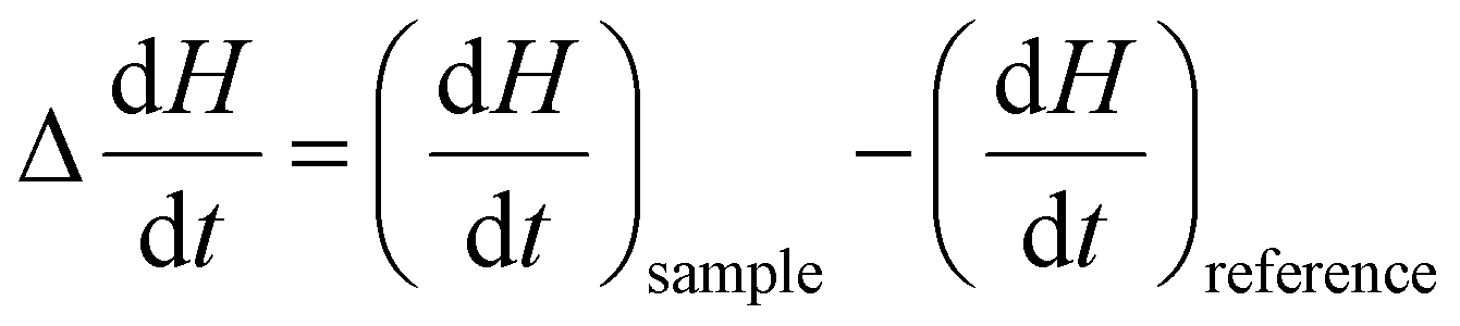 | (2) |
Typically, DSC is used to determine the melting temperature (Tm), crystallization temperature (Tc), glass transition temperature (Tg), and the corresponding enthalpy of these phase changes. The heat flow value can be either positive or negative based on the nature of the process. In an endothermic process, such as melting, heat is absorbed by the process. As a result, the value is positive. Conversely, in exothermic processes, such as crystallization or many cross-linking reactions, heat is released. In contrast, the glass transition is not associated with heat absorption or release but instead involves a change in heat capacity as the polymer transitions from a glass to a rubbery state.141 Crystallinity can be estimated by comparing the measured enthalpy of melting (ΔHm) to the enthalpy of melting for a 100% crystalline polymer  , using the equation:
 | (3) |
A simplified diagram of DSC, along with a representative DSC curve, is shown in Fig. 14.
 | ||
| Fig. 14 (A) Basic schematic of a DSC showing sample and reference pans with a heat sensor, (B) a representative DSC curve indicating glass transition (Tg), crystallization (Tc), and melting (Tm) events. | ||
In practice, DSC experiments are often carried out in a heat–cool–heat cycle. The first heating removes thermal history and processing effects (such as residual stress or incomplete crystallization), the controlled cooling step, and the second heating provides reproducible data on thermal transitions. Typical heating and cooling rates range from 5 to 20 °C min−1, depending on the sensitivity required, while sample sizes are usually 5–10 mg.
Like TGA, DSC detects the presence of copolymers or additives through shifts in thermal properties. Unlike TGA, which focuses on degradation and volatilization, DSC examines phenomena such as melting, glass transition, and crystallinity. DSC alone cannot be used to quantify the amount of an additive or the specific additive. Therefore, it is better to use DSC as a secondary validation characterization tool in identifying any polymer or additive.
In contrast to examining the crystallization and melting behavior of semicrystalline polymers, Rahman and Brazel utilized DSC to evaluate changes in the glass transition temperatures of poly (vinyl chloride) from traditional and ionic liquid (IL) plasticizers at 20 wt% loading.65 They found a significant reduction in the glass transition temperatures of PVC when traditional plasticizers were present compared to IL plasticizers. However, differences among the plasticization effects of ILs were also evident: imidazolium-based ILs showed the least reduction in Tg, reflecting stronger secondary bonding and partial incompatibility compared to other ILs. Thus, DSC served as a sensitive tool to quantify plasticization and distinguish the relative efficiency of different additives through shifts in Tg.65 This work suggests DSC could be used to infer the presence of compatibilizers that are used to increase the stability of polymers that do not blend. The addition of compatibilizers can result in additional peaks or glass transitions in the DSC results. An example is the study by Ferrarezi et al.63 DSC results showed that PLA exhibited a glass transition near 83 °C with crystallinity (∼18%). Blending with thermoplastic starch (TPS) or polyethylene glycol (PEG) resulted in additional glass transitions, with blends generally presenting two Tg values: a lower Tg (1) associated with TPS or PEG and a higher Tg (2) associated with PLA. The detection of two distinct transitions indicated phase separation in most blends, except TPS/PEG, which behaved as a miscible system. The PLA/TPS blend showed a reduced Tg (2) compared to neat PLA due to the plasticizing effect of glycerol, while ternary PLA/TPS/PEG blends exhibited even lower Tg (2) values, confirming the combined plasticization effects of glycerol and PEG.63 This study suggests that in the case of immiscible systems, the presence of additional Tg transitions may indicate the presence of additives.
The literature indicates that DSC serves as a powerful tool for monitoring phase behavior, yet it remains a fundamentally indirect and inferential method for additive analysis. As the discussed studies show, DSC does not directly detect or identify additives; instead, their presence is inferred from measurable shifts in crystallization kinetics, melting temperatures, or the appearance of secondary glass transitions. While these thermal signatures are sensitive enough to distinguish the efficiency of different plasticizers or the compatibility of blends, their interpretation depends heavily on prior knowledge of the additive system and the availability of calibration data. Furthermore, because overlapping transitions and complex thermal histories can obscure these effects, DSC lacks the structural specificity required for independent identification. Consequently, DSC is best utilized as a comparative technique to assess the influence of known additives on polymer performance, requiring support from spectroscopic and chromatographic methods to resolve the chemical identities of the additives responsible for changes in phase behavior.
6.3. XRD for polymer additive analysis
| nλ = 2dsin(θ) | (4) |
 | ||
| Fig. 15 (A) Simplified schematic of an X-ray diffraction (XRD) instrument, showing the X-ray source, sample, detector, and resulting diffraction pattern; (B) illustration of Bragg's law, relating diffraction angle (θ) and interplanar spacing (d). | ||
When additives are incorporated into a polymer matrix, they can influence the material's crystallinity, interplanar spacing, and overall molecular organization. Changes such as peak shifts, broadening, or intensity variations in the XRD diffractogram can indicate the presence of additives and reflect an altered crystal structure. Additionally, if the additives themselves are crystalline, they can contribute their own characteristic diffraction peaks to the XRD pattern. In this case, the additional diffraction peaks can be used to identify the additives themselves.
XRD requires careful sample preparation, and characterizing amorphous and weakly crystalline polymers using XRD is particularly challenging. This is because the diffraction patterns primarily arise from the crystalline regions in the sample, where atomic planes produce well-defined Bragg diffraction peaks. In contrast, amorphous regions lack long-range order and therefore produce broad humps instead of true diffraction peaks. Sample thickness also plays an important role, as thicker samples tend to absorb more X-rays and minimize observed diffraction.142–144 Thus, XRD can be used to monitor conformational changes only when the polymeric materials being analyzed are crystalline or semi-crystalline. For quantitative analysis, XRD can be used to estimate the relative concentration of additives in polymers by assessing changes in the polymer's degree of crystallinity. However, this method is not directly quantitative; it only offers an indirect, comparative measure based on how additives influence polymer crystallinity, and requires an understanding of which additives are present.
Conversely, if the additives are crystalline, their XRD peaks tend to be very weak relative to the intense peaks of the polymer matrix, making them difficult to identify. However, if the peaks are sufficiently distinct from the polymer background, various XRD analysis software can be used to compare experimental data with standard diffraction patterns from the ICDD (International Centre for Diffraction Data) PDF-4+ database or similar databases to identify these peaks. Compared to other characterization techniques, XRD has a poor limit of detection for additives within the sample. Thus, information provided by this technique needs to be coupled with other techniques to validate the findings.
An example of the use of XRD for additive studies in amorphous polymer is the work by Deraman et al.67 They studied the effect of plasticizers on the PVC-salt samples using XRD where PVC was blended with an added salt to form a polymer-salt complex, and then two plasticizers were introduced at known concentrations. The plasticizers used were ethylene carbonate (EC) and Bu3MeNTf2N (butyltrimethyl ammonium bis(trifluoromethylsulfonyl)imide). XRD was instrumental in revealing how varying plasticizer concentrations influenced the crystallinity of the PVC-salt samples. In both the EC and Bu3MeNTf2N-based systems, XRD patterns showed broad humps instead of sharp peaks, indicating predominantly amorphous structures. By analyzing the position and intensity of these amorphous humps, changes in crystallinity were evaluated. For example, in the EC system, increasing the plasticizer concentration from 5 to 15 wt% shifted the center of the hump from 2θ = 23° to 18°, along with changes in intensity indicating increased amorphous character and disrupted crystalline order. Similarly, in the Bu3MeNTf2N system, changes in the 2θ position and relative intensity of the hump were used to quantify the additive content of the sample, which correlated with the known concentration.67 The study conducted by Dankar et al. revealed that additives such as glycerol and lecithin influenced the crystallinity of potato puree by altering peak intensity.68 Glycerol significantly reduced crystallinity, indicating substantial disruption of starch structure, while lecithin enhanced order at higher concentrations. These changes demonstrated that XRD effectively inferred the presence of additives in the polymer matrix.68
The literature indicates that XRD serves as a specialized structural probe for monitoring additive-induced changes in polymer crystallinity, yet its effectiveness is fundamentally tied to the physical state of the components. As the discussed studies show, XRD provides valuable data on the presence of crystalline additives—such as mineral pigments and stabilizers—and can infer the influence of plasticizers by tracking shifts in amorphous humps or peak intensities. However, a significant comparative conclusion emerges: the utility of XRD is primarily restricted to additives that either possess inherent crystallinity or significantly disrupt the polymer's semi-crystalline order. Because many organic additives are amorphous or present at concentrations below the technique's detection limits, they often remain invisible against the dominant amorphous halo of the host polymer. Consequently, XRD is best utilized as a complementary tool for structural assessment rather than a primary identification method. It requires support from molecular spectroscopy to characterize unknown or non-crystalline additive packages.
Physical and thermal analyses provide inferential evidence of the presence of an additive by monitoring changes in the host polymer's behavior. While these methods are non-definitive for structural identification, their ability to detect anomalies at low concentrations makes them indispensable screening tools. The roadmap (Section 8) utilizes these thermal and structural signatures to assist with screening for potential additive content when the polymer is known.
7. Evolved gas analysis for polymer additive analysis
Evolved gas analysis (EGA) is an analytical approach used to study the gases released by a material as it is heated, along with the temperatures at which thermal decomposition or other chemical changes occur. In a typical EGA experiment, the sample is heated in a controlled manner while its mass loss is continuously monitored (thermogravimetry). As volatile compounds evolve, they are transferred directly to a suitable analyzer, such as a mass spectrometer or a FTIR spectrometer. These detectors provide complementary information: MS characterizes the molecular masses and fragmentation patterns of the gases, while FTIR spectroscopy identifies their functional groups. The combined thermal and analytical data yield a detailed profile of the material's composition and decomposition behavior.7.1. Fundamentals and limitations
The way volatile products are generated from a polymer strongly influences analytical resolution, specificity, and applicability for additive identification. The primary gas-generation approaches are flash pyrolysis (Py), multi-shot pyrolysis (MPy), and thermogravimetric analysis (TGA). Py employs rapid heating-often to 500–800 °C within seconds- to break polymer chains and release volatile fragments. Thermogravimetric analysis (TGA) uses slow, controlled heating under a specified atmosphere to monitor real-time weight loss as gases evolve from a sample. Multi-shot pyrolysis bridges the gap between flash pyrolysis and TGA by applying a programmed sequence of discrete pyrolysis temperatures. The advantage of using TGA to produce the gaseous product is that the thermal degradation profile is simultaneously obtained, allowing specific compounds in the evolved gas to be correlated with degradation events observed in the TGA degradation profile. Coupling TGA to spectral detectors enables simultaneous thermal and chemical characterization of the volatiles produced during the TGA analysis. A simplified diagram of evolved gas analysis is shown in Fig. 16. For instance, TGA-MS transfers the evolved gases directly into a mass spectrometer, providing rapid, highly sensitive detection and allowing determination of molecular masses and fragmentation patterns. This makes TGA-MS particularly useful for detecting low-level or inorganic gaseous products, although the absence of chromatographic separation can lead to overlapping signals in complex mixtures. In contrast, TGA-GC/MS introduces the evolved gases into a gas chromatograph prior to mass spectrometric detection, enabling correlation of each weight-loss event with well-resolved chromatographic peaks and associated mass spectra. These spectra can be compared against established reference databases, such as the NIST mass spectral library, to identify specific compounds. TGA-FTIR can likewise link mass-loss steps to infrared spectral features, providing direct information on the functional groups present in the released species. While TGA-GC/MS and TGA-MS approaches are powerful for mechanistic studies or pinpointing the precise temperatures at which additives volatilize, they are less commonly used for routine additive identification due to broader peaks from slower heating rates and the limited availability of libraries for TGA-derived products compared to pyrolysis GC/MS. TGA-FTIR, on the other hand, serves as an alternative for functional group assignment without chromatographic separation. It is quite common due to its relatively quick acquisition times and breadth of applications. It is often used to characterize polymers and inorganic materials, with about 50% of applications focused on these two classes.145,146 The off-gas produced during heating can lead to convoluted signals in the TGA data.147 The Gram-Schmidt plot contains all of the FTIR spectral information, showing signal intensity versus temperature (or time).148 From this, major thermal events can be identified and analyzed by examining the associated FTIR spectral data over a given temperature interval or time window. However, there are a few significant limitations related to TGA-FTIR. The FTIR spectroscopy must be done as quickly as possible to avoid secondary reactions in the gas phase during transfer. Moreover, there are often significant temperature differences between the furnace and transfer lines, which can lead to condensation and, as a result, clogging by higher-molecular-weight compounds. Aside from the technical limitations, coupled instrumentation is not nearly as common as merely having a TGA or FTIR spectrometer available. | ||
| Fig. 16 Basic schematic of evolved gas analysis (EGA), where gases released during TGA are transferred to spectral detectors such as FTIR, MS, or GC-MS for real-time analysis. | ||
7.2. Recent advances and current trends
The study by Fedelich et al. utilized TGA-MS to quantify a small number of known additives in a polymer.69 They spiked butyl rubber (BR, 130 mg) with methyl salicylate (0.5, 1, and 5 μL). Using these samples, TGA-MS was performed by heating the rubber up to 300 °C while monitoring both the mass loss and the ion signals by MS. Although the TGA curves of low-concentration samples closely resembled that of pure rubber, the MS provided enhanced sensitivity, showing a clear ion signal corresponding to the release of methyl salicylate. By integrating this signal and comparing it to calibration curves, the researchers quantified the additive in the microgram range and determined a detection limit of 0.5 μL.69 This demonstrates that TGA-MS can identify and quantify trace volatile additives in polymers even when TGA alone cannot resolve them.Tomiak et al. used TGA-GC/MS to determine changes in the decomposition of polyamide 6 mixed with expandable graphite or a mixture of aluminum diethylphosphinate (AlPi) and melamine polyphosphate (MPP).71 They analyzed the gaseous products at two heating rates, 20 K min−1 and 100 K min−1, and found a difference in peak-area percentages. A slight reduction in the elution temperature of certain gaseous products was also noted when PA6 was mixed with AlPi/MPP.71 Yousef et al. added carbon black to glass fiber-reinforced polymers to assess the pyrolysis recyclability of the composites.70 They found that phenol products were abundant during pyrolysis and suggested that a high phenol content would make the material viable for recycling for energy and recovering the glass fibers at low temperatures.70
These studies show that TGA-GC/MS is a facile method to determine the gaseous components of polymer degradation steps. However, it is quite difficult to determine the specific additives in polymers based solely upon TGA-GC/MS analysis because many additives degrade simultaneously with the polymer matrix, producing overlapping signals that complicate interpretation. Another related approach, TGA-FTIR, has also been explored for additive detection. While it shares many of the same advantages of real-time evolved gas monitoring, its application to polymer additives remains relatively limited. One notable exception is a comprehensive polymer additive identification study reported by Cuthbertson et al., using various techniques, including TGA-FTIR.52 They analyzed 21 different polymers from various classes using TGA-FTIR to detect and identify additives. They were able to identify monomers, typical degradation products, and additives in the evolved gases. For instance, they found alkanes in PE; benzene, hydrogen chloride, and 1-chloro-octance in PVC; styrene in PS; acetic acid in PVOH, EVOH, and EVA; and methyl methacrylate in PMMA. They identified butylated hydroxytoluene (BHT) within one of their PE samples, which is commonly used as an antioxidant to prevent degradation of polyolefins by UV or thermal mechanisms. One of the PVC samples evaluated was determined to contain 5-norbornene-2,3-dicarboxylic anhydride (NBDCA), a compound used primarily as a processing aid. They detected the presence of pentane in one PS sample and later confirmed from the vendor the use of pentane as a blowing agent.52
Evolved-gas analysis (EGA) provides high sensitivity for detecting volatile degradation products and trace additives, particularly when mass-loss curves alone are insufficient. However, the literature indicates that EGA remains less widespread than techniques such as Py-GC/MS for identifying unknown additive packages. This disparity stems from a significant analytical bottleneck: in complex polymer systems, many additives and polymer matrices decompose within similar temperature ranges. Such simultaneous decomposition produces overlapping signals that are difficult to interpret without the chromatographic separation provided by Py-GC/MS. Furthermore, the broader adoption of EGA is currently constrained by systemic factors, including high instrumentation costs, the requirement for specialized workflows, and a lack of comprehensive evolved-gas spectral libraries dedicated to polymer additives. Consequently, while EGA is a powerful tool for monitoring thermal behavior, its role in definitive additive identification is often relegated to a complementary rather than a primary technique.
Evolved gas analysis bridges the gap between thermal behavior and chemical identity by monitoring degradation products in real-time. Despite challenges with signal overlap and library availability, it provides a unique dimension of data for volatile components. This technique is integrated into the roadmap (Section 8) as a specialized path for characterizing additives that are otherwise inaccessible via traditional extraction methods.
8. Proposed roadmap
The analytical roadmap for evaluating additives in a polymer sample is rarely a “one-size-fits-all” approach; instead, it must be tailored to the specific level of prior knowledge of the sample's composition. In practice, researchers, analysts, quality engineers, and regulatory specialists typically encounter one of four scenarios, each requiring a distinct entry point into the analytical pathway:• Case 1: Known polymer and known additive. The analyst possesses significant prior knowledge of the material's composition. The primary objective is to determine the additive's relative concentration for quality control or performance verification.
• Case 2: Known polymer with unknown additive presence. The matrix has been identified, but it is unclear whether additives were introduced intentionally or accidentally. This is common when troubleshooting production defects or evaluating “equivalent” resin grades from new suppliers.
• Case 3: Unknown polymer and unknown additives. This represents a “blind” analysis in which both the host matrix and additives must be determined from scratch, as in competitor product deconstruction or environmental microplastics research.
• Case 4: Unknown polymer with a suspected or detected additive. This occurs when a specific additive signal, such as the white opacity of TiO2, a characteristic leaching product, or a distinct odor, is observed before the host matrix is identified.
As outlined in Fig. 17, these starting points determine the sequence of screening and characterization techniques employed. While the entry points differ, the workflows are intrinsically linked: the effort in Cases 3 and 4 includes analysis to determine the polymer type, while Cases 2 and 3 utilize techniques to detect and identify additives. Ultimately, all pathways converge on Case 1 once the chemical identities are established, enabling rigorous quantification.
 | ||
| Fig. 17 Flowchart outlining the roadmap for detection, identification, and quantification of polymer additives. | ||
Case 1 exhibits the highest level of certainty and is frequently a starting point for analysis in polymer production, compounding, and converting operations. Because chemical identities are established, the analytical objective is focused entirely on quantification. For additives such as antioxidants (AO), UV stabilizers (UVS), plasticizers (PL), processing aids (PA), slip additives (SA), compatibilizers (CMB), and impact modifiers (IM), selective solvent extraction followed by GC or HPLC enables specific quantification using calibration curves generated from known reference standards. When additives contain distinctive elemental markers such as phosphorus-based flame retardants (FR), metal-containing heat stabilizers (HS), inorganic additives (IA), or mineral fillers (FL), the workflow preferentially routes to ICP-based techniques or CHNS for elemental quantification. Spectroscopic techniques such as FTIR or NMR are incorporated only when additives exhibit strong, isolated signals that enable reliable calibration. In contrast, Py/TGA-GC methods serve as complementary routes for non-extractable or thermally unstable additives.
Case 2 prioritizes detection and chemical classification before attempting concentration measurements. The workflow begins with non-targeted spectroscopic screening using FTIR, Raman, and NMR. Because the polymer background is known, deviations from expected polymer signatures can be attributed to additives, enabling class-level inference for organic additives. When spectroscopic contrast is insufficient due to low loadings or spectral overlap, thermal and evolved-gas techniques (Py-GC/MS, TGA-FTIR) are used to provide characteristic fragments of FR, HS, IM, and other additives. Elemental screening can be used to reveal heteroatoms not present in the base polymer. Once the additive chemistry is narrowed, the scenario reverts to the Case 1 framework for quantification.
Case 3 is the most analytically challenging scenario, often involving materials that contain degraded polymers and additive byproducts. Because no chemical baseline exists, the strategy must first establish polymer identity. The effort begins with FTIR, Raman, and NMR spectroscopy to identify the polymer family and detect copolymers or blends. Property-based techniques (TGA, DSC, and XRD) can be integrated at this stage to differentiate polymer classes based on thermal behavior and crystallinity. Py-GC/MS and evolved gas analysis provide complementary polymer fingerprints while simultaneously revealing additive-related pyrolysis products. Once the polymer is identified, the system reverts to a Case 2 scenario to characterize the specific additive package.
Case 4 is triggered when additive-specific markers are identified during initial handling or preliminary screening. Examples include visual detection of inorganic fillers such as TiO2, identification of phosphorus-based flame retardants during elemental screening, and observation of additive migration into a surrounding medium. In this pathway, identifying the polymer matrix is the immediate priority to provide a quantitative baseline. By establishing the polymer identity through spectroscopic and thermal techniques, the analyst can define the matrix's contribution to spectroscopic and elemental analysis signals. Pyrolysis-based techniques (Py-GC/MS) are especially effective here, as they simultaneously confirm the polymer's pyrolysis fragments and the additive's marker compounds. Once the matrix is identified and its interference potential is understood, the workflow converges into Case 1 for final quantification.
Ultimately, the choice of an analytical entry point is a strategic decision based on the balance of known and unknown variables within a sample. While the initial stages of each case differ, prioritizing either rapid quantification, “blind” screening, or matrix identification, the overarching goal remains a complete chemical and physical characterization. By following this tiered approach, the analyst avoids the inefficiencies of redundant testing and ensures that the final quantification is grounded in an accurate understanding of the polymer matrix. Whether driven by industrial quality control, competitive benchmarking, or regulatory necessity, this integrated workflow provides a robust framework for navigating the inherent complexity of modern polymer-additive analysis.
9. Conclusion
Growing industrial demands for high-performance polymers, combined with increasing environmental pressures from global sustainability goals and recycling mandates, have made accurate additive analysis more critical than ever. As this review illustrates, the necessity for additive tracking spans the entire material lifecycle, beginning with polymer production, where inhibitors are used to control synthesis. During compounding operations, primary and secondary antioxidants must be precisely dosed to protect the resin from thermal stress, while converting operations introduce pigments and stabilizers as the polymer is shaped into final products. In both cases, quality assurance requires the careful monitoring of additive content and distribution. Beyond manufacturing, analytical methods are essential for determining the life span of materials by monitoring the leaching or degradation of these additives during service.The analytical challenge reaches its peak at the end-of-life stage, where the detection of restricted legacy additives is vital for technical traceability and the forensic analysis of environmental microplastics. Furthermore, the precise measurement of residual additives in reclaimed polymers is essential for determining the safety, quality, and potential for valorization of recycled streams. To navigate these complexities, our proposed roadmap provides a framework for selecting appropriate techniques based on the analysis's specific goal and the initial state of knowledge about the material. This strategic framework is structured around four primary scenarios, ranging from well-defined industrial formulations to completely unknown environmental fragments. By using the roadmap, researchers can determine whether to employ inferential screening tools such as TGA and DSC for rapid assessment or more resource-intensive molecular methods such as GC-MS and NMR spectroscopy for definitive characterization. Ultimately, the systematic application of these methodologies supports the development of safer materials and the valorization of reclaimed plastics, providing a foundation for a more transparent and sustainable polymer value chain.
Author contributions
Tanmay Rahman: writing – original draft, writing – review & editing, preparation of figures. Daniel Meadows: writing – review & editing, preparation of figures. Ke Zhan: writing – review & editing, preparation of figures. Harrish Kumar Senthil Kumar: writing – review & editing, preparation of figures. Marshall Smith: writing – review & editing, preparation of figures. Virginia A. Davis: writing – review & editing, supervision, funding acquisition. Bryan S. Beckingham: writing – review & editing, supervision, funding acquisition. Yucheng Peng: writing – review & editing, supervision, funding acquisition. Edward Davis: writing – review & editing, supervision, funding acquisition, conceptualization.Conflicts of interest
The authors declare no competing financial interest.Data availability
No primary research results, software or code have been included and no new data were generated or analysed as part of this review.Acknowledgements
The authors are grateful for the financial support provided by NSF #2132093 and NIST #60NANB24D018. The authors thank Zachary Bradford for drawing all chemical structures displayed in this work.References
- J. Brady, T. Dürig, P. Lee and J.-X. Li, in Developing solid oral dosage forms, Elsevier, 2017, pp. 181–223 Search PubMed.
- C. A. Harper, Handbook of plastics technologies: the complete guide to properties and performance, McGraw-Hill, 2006 Search PubMed.
- K. Zhan, D. Meadows, L. Levy, R. Hou, T. Rahman, V. Davis, E. Davis, B. S. Beckingham, B. Via and T. Elder, Polym. Degrad. Stab., 2024, 222, 110710 CrossRef CAS.
- R. Pfaendner, in Handbook of Polymer Synthesis, Characterization, and Processing, ed. E. Saldívar-Guerra and E. Vivaldo-Lima, John Wiley & Sons, Inc., 2013, ch. 11, pp. 225–247 Search PubMed.
- J. George, M. S. Sreekala and S. Thomas, Polym. Eng. Sci., 2001, 41, 1471–1485 CrossRef CAS.
- V. Marturano, P. Cerruti and V. Ambrogi, Phys. Sci. Rev., 2017, 2, 20170138 Search PubMed.
- M. Ahmad, D. Shukla, Y. Zhu and O. D. Velev, ACS Appl. Mater. Interfaces, 2025, 17, 17316–17329 CrossRef CAS PubMed.
- U. Heudorf, V. Mersch-Sundermann and J. Angerer, Int. J. Hyg. Environ. Health, 2007, 210, 623–634 Search PubMed.
- Y. Guo and K. Kannan, Anal. Bioanal. Chem., 2012, 404, 2539–2554 CrossRef CAS PubMed.
- G. Song, J. Tao, L. Cui, S. Ma, Q. Lv, H. Chen, X. Liu, Y. Yang and D. Chen, Environ. Sci. Technol. Lett., 2024, 11, 23–28 Search PubMed.
- A. D. Godwin, in Applied Plastics Engineering Handbook, ed. M. Kutz, Elsevier, 3rd edn, 2024, ch. 26, pp. 595–618 Search PubMed.
- Plasticizers Market by type (phthalate and non-phthalate), Application (Floorings & Wall Coverings, Films & Sheets, Coated Fabrics, Wires & Cabals, Consumer Goods), and Region (North America, Europe, Middle East, and Africa)-Global, Forecast to 2027 Search PubMed , https://www.marketsandmarkets.com/Market-Reports/plasticizers-market-688.html (accessed 23 December, 2025).
- E. Kriek, Biochim. Biophys. Acta, Rev. Cancer, 1974, 355, 177–203 CrossRef CAS PubMed.
- X. Meng, W. Chen, Z. Xin and C. Wu, J. Vinyl Addit. Technol., 2018, 24, 124–129 Search PubMed.
- K. Schwetlick, Pure Appl. Chem., 1983, 55, 1629–1636 CrossRef CAS.
- J. Ngunjiri, P. Michaeleen and S. Rahul, Microsc. Microanal., 2021, 27, 2010–2010 CrossRef.
- R. Höfer, in Polymer Science: A Comprehensive Reference, ed. K. Matyjaszewski and M. Möller, Elsevier, 2012, vol. 10, ch. 10.21, pp. 369–381 Search PubMed.
- C. Ye, Z. Liu, J. Li, Y. Ni, Z. Xin and S. Zhao, J. Polym. Res., 2023, 30, 7 CrossRef CAS.
- R. Li, S. Xu, J. Xu, T. Pan, B. Sun and L. Dang, Polymers, 2023, 15, 2575 CrossRef CAS PubMed.
- J. G. Drobny, in Handbook of Thermoplastic Elastomers, ed. J. G. Drobny, William Andrew, 2nd edn, 2014, ch. 3, pp. 17–32 Search PubMed.
- C. A. De Wit, Chemosphere, 2002, 46, 583–624 Search PubMed.
- S. V. Levchik and E. D. Weil, J. Fire Sci., 2006, 24, 345–364 CrossRef CAS.
- C. A. Wilkie and A. B. Morgan, Fire Retardancy of Polymeric Materials, CRC Press, Boca Raton, 3rd edn, 2024 Search PubMed.
- E. Yousif and R. Haddad, SpringerPlus, 2013, 2, 398 Search PubMed.
- P. Gijsman, J. Hennekens and D. Tummers, Polym. Degrad. Stab., 1993, 39, 225–233 Search PubMed.
- D. Lala and J. F. Rabek, Polym. Degrad. Stab., 1981, 3, 383–396 Search PubMed.
- S. Kemmlein, D. Herzke and R. J. Law, J. Chromatogr. A, 2009, 1216, 320–333 CrossRef CAS PubMed.
- P. Fauser, K. Vorkamp and J. Strand, Mar. Pollut. Bull., 2022, 177, 113467 Search PubMed.
- Y. Liu, M. Ahmad, R. A. Venditti, O. D. Velev and Y. Zhu, Adv. Electron. Mater., 2024, 10, 2300792 Search PubMed.
- R. Valand, S. Tanna, G. Lawson and L. Bengtström, Food Addit. Contam.,: Part A, 2020, 37, 19–38 Search PubMed.
- J. Schmidt, M. Haave and W. Wang, RSC Adv., 2025, 15, 13041–13052 Search PubMed.
- N. Singh, B. Mann, R. Sharma, A. Verma, N. R. Panjagari and K. Gandhi, Food Packag. Shelf Life, 2022, 34, 100975 CrossRef CAS.
- L. Bernard, D. Bourdeaux, B. Pereira, N. Azaroual, C. Barthélémy, C. Breysse, P. Chennell, R. Cueff, T. Dine, T. Eljezi, F. Feutry, S. Genay, N. Kambia, M. Lecoeur, M. Masse, P. Odou, T. Radaniel, N. Simon, C. Vaccher, C. Verlhac, M. Yessaad, B. Décaudin and V. Sautou, Talanta, 2017, 162, 604–611 CrossRef CAS PubMed.
- C. Zeddam and N. Belhaneche-Bensemra, Int. J. Polym. Mater., 2010, 59, 318–329 Search PubMed.
- L. A. Agustina, Y. D. Lestari, A. A. Adhinanda, M. N. Ariesta, J. Choi, Y. P. Prananto and R. Febriani, Acta Chim. Asiana, 2024, 7, 366–376 Search PubMed.
- Q. Li, Y. Tang, Z. Yan and P. Zhang, Spectrochim. Acta, Part A, 2017, 180, 154–160 CrossRef CAS PubMed.
- T. Nørbygaard and R. W. Berg, Appl. Spectrosc., 2004, 58, 410–413 CrossRef PubMed.
- R. W. Berg and A. D. Otero, Vib. Spectrosc., 2006, 42, 222–225 CrossRef CAS.
- J. Ehret-Henry, J. Bouquant, D. Scholler, R. Klinck and A. Feigenbaum, Food Addit. Contam., 1992, 9, 303–314 CrossRef CAS PubMed.
- F. Coelho, L. F. Vieira, R. Benavides, M. M. d. S. Paula, A. M. Bernardin, R. F. Magnago and L. d. Silva, Int. Polym. Process., 2015, 30, 574–584 Search PubMed.
- F. P. Miknis and K. P. Thomas, Road Mater. Pavement Des., 2008, 9, 59–72 CrossRef.
- E. Zygadło-Monikowska, Z. Florjańczyk, A. Tomaszewska, M. Pawlicka, N. Langwald, R. Kovarsky, H. Mazor, D. Golodnitsky and E. Peled, Electrochim. Acta, 2007, 53, 1481–1489 CrossRef.
- K. V. Alexeeva and L. S. Solomatina, J. Chromatogr. A, 1986, 364, 105–112 CrossRef.
- J. W. Sinclair, L. Schall and N. T. Crabb, J. Chromatogr. Sci., 1980, 18, 30–34 Search PubMed.
- P. Perlstein and P. Orme, J. Chromatogr. A, 1985, 325, 87–93 CrossRef CAS.
- F. C.-Y. Wang and A. D. Burleson, J. Chromatogr. A, 1999, 833, 111–119 Search PubMed.
- J. C. J. Bart, J. Anal. Appl. Pyrolysis, 2001, 58–59, 3–28 Search PubMed.
- P. G. Demertzis and R. Franz, Food Addit. Contam., 1998, 15, 93–99 CrossRef CAS PubMed.
- H. El Mansouri, N. Yagoubi and D. Ferrier, Chromatographia, 1998, 48, 491–496 CrossRef CAS.
- B. Li, Z.-W. Wang, Q.-B. Lin, C.-Y. Hu, Q.-Z. Su and Y.-M. Wu, J. Chromatogr. Sci., 2014, 53, 1026–1035 Search PubMed.
- M. Thilén and R. Shishoo, J. Appl. Polym. Sci., 2000, 76, 938–946 CrossRef.
- A. A. Cuthbertson, C. Lincoln, J. Miscall, L. M. Stanley, A. K. Maurya, A. S. Asundi, C. J. Tassone, N. A. Rorrer and G. T. Beckham, Green Chem., 2024, 26, 7067–7090 RSC.
- H. Liang, D. Rodrigue and J. Brisson, J. Appl. Polym. Sci., 2015, 132, 42692 Search PubMed.
- Y. Hu, D. M. Stevens, S. Man, R. M. Crist and J. D. Clogston, Drug Delivery Transl. Res., 2019, 9, 1057–1066 Search PubMed.
- J. S. F. Pereira, C. L. Knorr, L. S. F. Pereira, D. P. Moraes, J. N. G. Paniz, E. M. M. Flores and G. Knapp, J. Anal. At. Spectrom., 2011, 26, 1849 Search PubMed.
- M. Hemmerlin, J. M. Mermet, M. Bertucci and P. Zydowicz, Spectrochim. Acta, Part B, 1997, 52, 421–430 CrossRef.
- H. Dvir, M. Goldraich, M. Gottlieb, S. Daren and J. Lopez Cuesta, Polym. Degrad. Stab., 2001, 74, 465–474 CrossRef CAS.
- R. D. Holbrook, J. M. Davis, K. C. K. Scott and C. Szakal, J. Microsc., 2012, 246, 143–152 CrossRef CAS PubMed.
- E. Fries, J. H. Dekiff, J. Willmeyer, M.-T. Nuelle, M. Ebert and D. Remy, Environ. Sci.: Processes Impacts, 2013, 15, 1949–1956 RSC.
- S. Won, K.-H. Ko, C.-J. Park, L.-R. Cho and Y.-H. Huh, J. Adv. Prosthodont., 2022, 14, 315 CrossRef PubMed.
- K. Sałasińska, M. Borucka, M. Celiński, A. Gajek, W. Zatorski, K. Mizera, M. Leszczyńska and J. Ryszkowska, Adv. Polym. Technol., 2017, 37, 2394–2410 CrossRef.
- D. Losic, F. Farivar, P. L. Yap and A. Karami, Anal. Chem., 2021, 93, 11859–11867 CrossRef CAS PubMed.
- M. M. F. Ferrarezi, M. de Oliveira Taipina, L. C. Escobar da Silva and M. d. C. Gonçalves, J. Polym. Environ., 2012, 21, 151–159 CrossRef.
- S.-G. Hong, T.-K. Gau and S.-C. Huang, J. Therm. Anal. Calorim., 2010, 103, 967–975 CrossRef.
- M. Rahman and C. S. Brazel, Polym. Degrad. Stab., 2006, 91, 3371–3382 CrossRef CAS.
- B. Papajanı, E. Vataj, A. Hasımı and A. Sinanaj, in Published in part at RAD Conf. Proc., 2018, vol. 3, pp. 236–240.
- S. K. Deraman, N. A. Tajuddin and H. Hanibah, Sci. Lett., 2024, 18, 78–91 Search PubMed.
- I. Dankar, A. Haddarah, F. E. L. Omar, M. Pujolà and F. Sepulcre, Food Chem., 2018, 260, 7–12 CrossRef CAS PubMed.
- N. Fedelich, Evolved Gas Analysis Hyphenated Techniques, Hanser Publishers, Munich, Germany, 2019 Search PubMed.
- S. Yousef, J. Eimontas, N. Striūgas and M. A. Abdelnaby, Energy, 2021, 233, 121167 CrossRef CAS.
- F. Tomiak, A. Schoeffel, K. Rathberger and D. Drummer, Polymers, 2021, 13, 2712 CrossRef CAS PubMed.
- Analytical Resolution vs. Detection Limit, https://www.eag.com/wp-content/uploads/2016/11/M-006916-Bubble-Chart.pdf, (accessed 23 December, 2025).
- J. D. Schuttlefield and V. H. Grassian, J. Chem. Educ., 2008, 85, 279 CrossRef CAS.
- G.-L. Liu and S. G. Kazarian, Analyst, 2022, 147, 1777–1797 RSC.
- C. Berthomieu and R. Hienerwadel, Photosynth. Res., 2009, 101, 157–170 CrossRef CAS PubMed.
- K. Vrieze, Recl. Trav. Chim. Pays-Bas, 1991, 110, 97–97 CrossRef.
- A. Gonzalvez, S. Garrigues, M. De La Guardia and S. Armenta, Anal. Methods, 2011, 3, 43–52 Search PubMed.
- L. Lux, Y. Phal, P.-H. Hsieh and R. Bhargava, Appl. Spectrosc., 2022, 76, 105–117 Search PubMed.
- J. C. J. Bart, Plastics Additives: Advanced Industrial Analysis, IOS Press, 2006 Search PubMed.
- P. Griffiths and J. M. Chalmers, Handbook of Vibrational Spectroscopy, John Wiley & Sons, Ltd, 2006 Search PubMed.
- R. S. Das and Y. K. Agrawal, Vib. Spectrosc., 2011, 57, 163–176 CrossRef CAS.
- G. S. Bumbrah and R. M. Sharma, Egy. J. Forenic Sci., 2016, 6, 209–215 Search PubMed.
- A. Orlando, F. Franceschini, C. Muscas, S. Pidkova, M. Bartoli, M. Rovere and A. Tagliaferro, Chemosensors, 2021, 9, 262 CrossRef CAS.
- A. Klisińska-Kopacz, B. Łydżba-Kopczyńska, M. Czarnecka, T. Koźlecki, J. del Hoyo Mélendez, A. Mendys, A. Kłosowska-Klechowska, M. Obarzanowski and P. Frączek, J. Raman Spectrosc., 2019, 50, 213–221 CrossRef.
- D. O. Hummel, Atlas of Plastics Additives Analysis by Spectroscopic Methods, Springer Berlin, Heidelberg, Germany, 1st edn, 2002 Search PubMed.
- G. J. Martin, M. L. Martin and J.-P. Gouesnard, 15N-NMR Spectroscopy (NMR Basic Principles and Progress), Springer-Verlag, Berlin, Heidelberg, ed. P. Diehl, 1989, pp. 1–69 Search PubMed.
- F. Hammerath, Magnetism and Superconductivity in Iron-based Superconductors as Probed by Nuclear Magnetic Resonance, Vieweg+Teubner Verlag Wiesbaden, 2012 Search PubMed.
- H. Günther, NMR spectroscopy: basic principles, concepts and applications in chemistry, John Wiley & Sons, 2013 Search PubMed.
- M. D. Reily and J. C. Lindon, Metabonomics Toxic. Assess., 2005, 75–104 CAS.
- I. Y. Slonim, The NMR of polymers, Springer Science & Business Media, 2012 Search PubMed.
- S. B. Chakrapani, M. J. Minkler and B. S. Beckingham, Analyst, 2019, 144, 1679–1686 RSC.
- S. B. Chakrapani, PhD thesis, Auburn University, 2019.
- H. K. Senthil Kumar, Y. Noh, A. L. Bachmann and B. S. Beckingham, Magn. Reson. Chem., 2024, 62, 619–628 CrossRef CAS PubMed.
- H. Kessler, M. Gehrke and C. Griesinger, Angew. Chem., Int. Ed. Engl., 1988, 27, 490–536 Search PubMed.
- D. A. Meadows, H. K. S. Kumar, E. W. Davis, B. S. Beckingham and V. A. Davis, Polym. Degrad. Stab., 2025, 232, 111099 CrossRef CAS.
- C. B. Crawford and B. Quinn, in Microplastic Pollutants, ed. C. B. Crawford and B. Quinn, Elsevier, 2017, ch. 10, pp. 219–267 Search PubMed.
- R. Evers, PhD thesis, University of Portsmouth, 2014.
- J. P. Dworzanski, L. Berwald, W. H. McClennen and H. L. C. Meuzelaar, J. Anal. Appl. Pyrolysis, 1991, 21, 221–232 CrossRef CAS.
- T. Mitsui, M. Hida and Y. Fujimura, J. Anal. Appl. Pyrolysis, 1995, 32, 205–212 CrossRef CAS.
- R. Milina, J. Anal. Appl. Pyrolysis, 1981, 3, 179–183 Search PubMed.
- H. Nakagawa, S. Tsuge and K. Murakami, J. Anal. Appl. Pyrolysis, 1986, 10, 31–40 CrossRef CAS.
- T. P. Wampler, Applied Pyrolysis Handbook, CRC Press, Boca Raton, 2006 Search PubMed.
- O. D. Sparkman, Z. Penton and F. G. Kitson, Gas chromatography and mass spectrometry: a practical guide, Academic press, 2011 Search PubMed.
- S. Mao, S. Tsuge, H. Ohtani, S. Uchijima and A. Kiyokawa, Polymer, 1998, 39, 143–149 CrossRef CAS.
- F. C.-Y. Wang, J. Chromatogr. A, 2000, 883, 199–210 CrossRef CAS PubMed.
- C. M. Rochman, Marine anthropogenic litter, 2015, pp. 117–140 Search PubMed.
- M. Herrera, G. Matuschek and A. Kettrup, J. Anal. Appl. Pyrolysis, 2003, 70, 35–42 CrossRef CAS.
- S. H. d. l. Torre, in Recent Perspectives in Pyrolysis Research, ed. M. Bartoli and M. Giorcelli, IntechOpen, London, UK, 2022, ch. 15 Search PubMed.
- L. Hermabessiere, J. Receveur, C. Himber, D. Mazurais, A. Huvet, F. Lagarde, C. Lambert, I. Paul-Pont, A. Dehaut and R. Jezequel, Sci. Total Environ., 2020, 749, 141651 Search PubMed.
- B. Prathap, A. Dey, P. Johnson and P. Arthanariswaran, Int. J. Novel Trends Pharm. Sci., 2013, 3, 15–23 CAS.
- V. Gupta, A. D. K. J. Jain, N. Gill and K. Guptan, Int. Res. J. Pharm. Appl. Sci., 2012, 2, 17–25 Search PubMed.
- B. K. Sharma, Instrumental Methods of Chemical Analysis, Krishna Prakashan, Meerut, India, 1981 Search PubMed.
- J. Gilbert, M. J. Shepherd, J. R. Startin and M. A. Wallwork, J. Chromatogr. A, 1982, 237, 249–261 CrossRef CAS.
- M. Bird, C. Keitel and W. Meredith, in Biochar: A Guide to Analytical Methods, ed. B. Singh, M. Camps-Arbestain and J. Lehmann, CSIRO Publishing, Clayton South, Australia, 2017, pp. 39–50 Search PubMed.
- Analytical Methods Committee, Evaluation of analytical instrumentation. Part XIX. CHNS elemental analysers, Accredit. Qual. Assur., 2006, 11, 569–576 Search PubMed.
- V. P. Fadeeva, V. D. Tikhova and O. N. Nikulicheva, J. Anal. Chem., 2008, 63, 1094–1106 CrossRef CAS.
- R. F. André, J. Brandt, J. Schmidt, N. López-Salas, M. Odziomek and M. Antonietti, Carbon, 2024, 223, 118946 CrossRef.
- N. Z. Habib, I. Kamaruddin, I. M. Tan and M. Napiah, in Presented in part at 7th RILEM International Conference on Cracking in Pavements, Delft University of Technology, The Netherlands, June 2012.
- Y. Jia, J. Li, Y. Wang, J. Jin and H. Liu, Prog. Org. Coat., 2021, 156, 106249 CrossRef CAS.
- J. W. Olesik, Anal. Chem., 1991, 63, 12A–21A CrossRef CAS.
- S. R. Khan, B. Sharma, P. A. Chawla and R. Bhatia, Food Anal. Methods, 2022, 15, 666–688 CrossRef.
- G. Tyler and J. Yvon, ICP Optical Emission Spectroscopy Technical Note, 1995, vol. 5 Search PubMed.
- P. W. J. M. Boumans and N. W. Barnett, Anal. Chim. Acta, 1987, 201, 365 CrossRef.
- P. K. Booth and C. W. McLeod, Microchim. Acta, 1989, 99, 283–289 CrossRef.
- J. Marshall, J. Franks, I. Abell and C. Tye, J. Anal. At. Spectrom., 1991, 6, 145–150 RSC.
- D. R. Anderson, C. W. McLeod and T. A. Smith, J. Anal. At. Spectrom., 1994, 9, 67–72 RSC.
- P. J. Fordham, J. W. Gramshaw, L. Castle, H. M. Crews, D. Thompson, S. J. Parry and E. McCurdy, J. Anal. At. Spectrom., 1995, 10, 303–309 RSC.
- E. M. M. Flores, P. A. Mello, S. R. Krzyzaniak, V. H. Cauduro and R. S. Picoloto, Rapid Commun. Mass Spectrom., 2020, 34, e8727 Search PubMed.
- X. Bu, T. Wang and G. Hall, J. Anal. At. Spectrom., 2003, 18, 1443 RSC.
- D. Clases and R. Gonzalez de Vega, Anal. Bioanal. Chem., 2022, 414, 7337–7361 Search PubMed.
- M. Bonta and A. Limbeck, J. Anal. At. Spectrom., 2018, 33, 1631–1637 RSC.
- D. Shindo and T. Oikawa, in Analytical Electron Microscopy for Materials Science, ed. D. Shindo and T. Oikawa, Springer Tokyo, Japan, 2002, ch. 4, pp. 81–102 Search PubMed.
- A. V. Girão, G. Caputo and M. C. Ferro, in Compr. Anal. Chem, ed. T. A. P. Rocha-Santos and A. C. Duarte, Elsevier, 1st edn, 2017, vol. 75, pp. 153–168 Search PubMed.
- D. Son, S. Cho, J. Nam, H. Lee and M. Kim, Polymers, 2020, 12, 1053 CrossRef CAS PubMed.
- L. S. Birnbaum and F. S. Daniele, Environ. Health Perspect., 2004, 112, 9–17 CrossRef CAS PubMed.
- N. S. Allen and M. Edge, J. Vinyl Addit. Technol., 2021, 27, 211–239 Search PubMed.
- X. Llovet, A. Moy, P. T. Pinard and J. H. Fournelle, Prog. Mater. Sci., 2021, 116, 100673 CrossRef CAS.
- H.-K. Kim, H.-Y. Ha, J.-H. Bae, M. K. Cho, J. Kim, J. Han, J.-Y. Suh, G.-H. Kim, T.-H. Lee, J. H. Jang and D. Chun, Sci. Rep., 2020, 10, 13699 CrossRef CAS PubMed.
- M. Tiwari, S. K. Sahu, T. Rathod, R. C. Bhangare, P. Y. Ajmal, V. Pulhani and A. Vinod Kumar, Trends Environ. Anal. Chem., 2023, 40, e00221 CrossRef CAS.
- N. Saadatkhah, A. Carillo Garcia, S. Ackermann, P. Leclerc, M. Latifi, S. Samih, G. S. Patience and J. Chaouki, Can. J. Chem. Eng., 2019, 98, 34–43 CrossRef.
- C. Schick, Anal. Bioanal. Chem., 2009, 395, 1589–1611 CrossRef CAS PubMed.
- J. Epp, in Materials characterization using nondestructive evaluation (NDE) methods, Elsevier, 2016, pp. 81–124 Search PubMed.
- A. A. Bunaciu, E. G. UdriŞtioiu and H. Y. Aboul-Enein, Crit. Rev. Anal. Chem., 2015, 45, 289–299 CrossRef CAS PubMed.
- A. Ali, Y. W. Chiang and R. M. Santos, Minerals, 2022, 12, 205 CrossRef CAS.
- B. H. Stuart, Infrared spectroscopy: fundamentals and applications, John Wiley & Sons, 2004 Search PubMed.
- S. Materazzi and S. Vecchio, Appl. Spectrosc. Rev., 2013, 48, 654–689 CrossRef.
- T. Hatakeyama and F. i. Quinn, Thermal analysis: fundamentals and applications to polymer science, Wiley, 1999 Search PubMed.
- C. A. Smith, Polym. Test., 2016, 52, 234–245 CrossRef CAS.
| This journal is © The Royal Society of Chemistry 2026 |