
 Open Access Article
 This Open Access Article is licensed under a
 Creative Commons Attribution 3.0 Unported Licence
High-speed liquid switching and on-chip force sensing reveal the transient mechanical response of MscL in Synechocystis sp. PCC 6803
Xu
Du
 ab,
Masaru
Tsujii
c,
Nobuyuki
Uozumi
c and
Fumihito
Arai
*bd
ab,
Masaru
Tsujii
c,
Nobuyuki
Uozumi
c and
Fumihito
Arai
*bd
aKey Laboratory of Intelligent Flexible Actuation and Control in Universities of Jiangsu Province and School of Mechanical Engineering, Jiangsu University, Zhenjiang 212003, China
bDepartment of Micro-Nano Mechanical Science and Engineering, Nagoya University, Furo-cho, Chikusa-ku, Nagoya 464-8603, Japan. E-mail: arai-fumihito@g.ecc.u-tokyo.ac.jp; Tel: +81 3 5841 8818
cDepartment of Biomolecular Engineering, Tohoku University, 6-6-07 Aobayama, Aoba-ku, Sendai 980-8579, Japan
dDepartment of Mechanical Engineering, The University of Tokyo, 7-3-1 Hongo, Bunkyo-ku, Tokyo 113-8656, Japan
First published on 12th March 2026
Abstract
How cells mechanically respond to rapid stimulation in the extracellular microenvironment is a key question for understanding the physiological functions of mechanosensitive (MS) channels. In this study, we investigated the single Synechocystis sp. PCC 6803 cell transient mechanical response under osmotic downshock using a microfluidic system that assembles a robot-integrated microfluidic chip with a synchronized injection–aspiration liquid switching module. Through theoretical analysis and system optimization, we achieved high-speed, localized liquid switching on the millisecond scale while simultaneously measuring cell deformation and reactive force. Using this system, we compared the Young's modulus of wild-type (WT) and MS channel-deficient mutant (ΔmscL) cells in hypoosmotic and hyperosmotic conditions, and quantified their transient mechanical responses under millisecond-scale liquid switching times. In particular, we compared the response time and key deformation parameters (expansion and shrinkage rates) of the two strains when the cells were compressed under osmotic downshock. Multi-parameter analysis suggests that the differences between WT and ΔmscL cells are consistent with a transient contribution of MscL during osmotic downshock, which may mitigate membrane tension buildup and delay the mechanical response under compression. These findings advance the understanding of cellular mechanical adaptation under rapid environmental transitions and demonstrate the broad applicability of this integrated microfluidic system for high-speed liquid switching and synchronous force sensing in single-cell mechanobiological studies.
Introduction
Mechanosensitive (MS) channels are membrane proteins that enable cells to sense and respond to mechanical stimulation from the external environment.1 These channels are involved in physiological processes such as touch sensation, hearing, cancer cell migration, and osmotic regulation.2–5Synechocystis sp. PCC 6803 is a unicellular cyanobacterium with an approximately spherical geometry and a typical diameter of about 1.5–3 μm (average ∼2 μm).6 As a Gram-negative bacterium, its cell envelope consists of an inner cytoplasmic membrane, a thin peptidoglycan layer, and an outer membrane. Synechocystis has a simple cellular organization and can be easily cultivated in the laboratory. It is widely used as a model organism in studies of photosynthesis, nitrogen fixation, and MS channel-mediated osmotic regulation.7–9 When Synechocystis cells experience a rapid decrease in extracellular osmolarity (osmotic downshock), water influx causes the cells to swell. To prevent membrane rupture, MS channels open within the sub-second timescale in response to membrane tension, releasing intracellular solutes and allowing the cell volume to adjust rapidly to the new osmotic condition (Fig. 1).10 | ||
| Fig. 1 Schematic illustration of the osmotic downshock process. When extracellular osmolarity suddenly decreases, water influx induces rapid cell swelling, and MS channels such as MscL open to release intracellular solutes, reducing membrane tension and preventing rupture. | ||
Given the critical role of MS channels, developing effective methods to detect cellular responses to extracellular stimulation is essential for uncovering their gating mechanisms. At present, patch-clamp electrophysiology remains the most widely used approach for studying ion channels, including MS channels. In conventional protocols, negative pressure is applied to membrane patches to induce localized membrane tension, thereby triggering channel opening.11,12 The resulting transmembrane ionic currents are recorded to characterize gating behavior, conductance states, and activation kinetics. In addition, small-molecule compounds such as IRS-16 can directly activate MS channels, and their opening can be detected through patch-clamp recordings.13 MS channels have also been reconstituted into droplet interface bilayers (DIBs), where periodic compression of the droplets generates membrane tension to induce gating.14 Furthermore, voltage-induced activation has been reported in supported lipid bilayers.15
While these methods have provided important insights into the biophysical properties of MS channels, they largely rely on excised membrane patches or artificial bilayer systems, and most operate under quasi-static or low-speed stimulation conditions. As a result, these approaches have limited ability to capture the dynamic, whole-cell mechanical responses that occur during rapid osmotic stimulation in native environments.
In contrast, osmotic stimulation methods can rapidly change extracellular osmolarity, inducing whole-cell deformation and avoiding non-physiological shear stress associated with local stretching. Among them, stopped-flow methods have been widely used at the cell population level to investigate osmotic shocks.16,17 However, they lack precise detection capability for mechanical responses at the single-cell level, and the rapid mixing of solutions in these systems often causes flow disturbances that impede integration with force sensors.
Given that MS channels such as the mechanosensitive channel of large conductance (MscL) respond to osmotic downshock within tens of milliseconds, changing the extracellular environment on the millisecond scale would make it possible to reveal how these channels respond during the early stage of activation.17 Currently, the transient mechanical response of single cells to millisecond-scale extracellular stimulation remains unclear, and experimental studies are limited.
Microfluidic chip technology, which utilizes micro-scale channels and fluid control, has been widely applied in biomedical and chemical analysis owing to its advantages of high throughput, small sample volume, ease of observation, and integration of functional components.18–21 By integrating driving, sensing, cell manipulation, and liquid switching functions into microfluidic chips (robot-integrated microfluidic chip), cells can be simultaneously stimulated and detected within a precisely controlled microenvironment.22 This enables real-time, non-destructive measurement of single-cell mechanical responses under dynamic extracellular stimulation.23 Traditional microfluidic chips integrated with force sensors primarily achieve liquid switching by directly injecting new solutions around the cell.24,25 However, precise control of fluid injection and flow velocity remains challenging. This often leads to long switching times and undesired disturbances to force-sensing structures, limiting the ability to continuously measure the dynamic response of a single cell. Our group previously developed a closed robot-integrated microfluidic chip that used laminar flow to measure the mechanical response of single cells under osmotic downshock.26 Nevertheless, the liquid switching time of approximately 0.5 s was much longer than the characteristic mechanical response time of Synechocystis cells under osmotic downshock.17 Therefore, the system was unable to observe the response process of cells, and the difficulty in balancing pressure within the sensing region of the closed chip caused significant interference to the integrated force sensor. To achieve high-speed liquid switching, we subsequently designed an external dual-pump system. However, the actual liquid switching time fluctuated between the millisecond and second range, which made it impossible to perform a reliable statistical analysis of the transient mechanical responses of cells.27
In this study, we investigate the single Synechocystis cell transient response under osmotic downshock using the microfluidic system that assembles a liquid switching function with on-chip force and displacement sensing. Through theoretical analysis and optimization of the liquid switching module, we achieved high-speed, localized liquid switching within the millisecond scale. This advancement enabled the first quantitative investigation of single-cell transient mechanical responses under different liquid switching times. We investigated the mechanical behavior of Synechocystis cells under osmotic downshock, focusing on the influence of liquid switching time on single-cell mechanical response. Multi-parameter analysis of Young's modulus, response time, expansion rate, and shrinkage rate revealed the mechanical regulation mediated by the MscL. This work provides new insight into the role of MS channels in maintaining mechanical stability under rapid osmotic stimulation and demonstrates the capability of this system for single-cell mechanobiological analysis.
Methods
Experimental setup
The experimental setup is shown in Fig. 2. The microfluidic chip was fixed onto the microscope stage using a jig, and the original solution was added to its surface using a pipette. Target single cells were manipulated into position between the sensing and pushing probes (on-chip probes) of the microfluidic chip using optical tweezers and subsequently compressed by an external piezo-actuator. For the liquid switching module, the syringe pump was used to preload switched solutions into the channels of the liquid switching module. A 3D manipulator was employed to adjust the relative position between the 3D-printed probe and the chip surface. A signal generator with a trigger function was used to apply synchronized injection and aspiration signals to the two piezo-stacks, enabling dynamic liquid switching around the target cell. The liquid switching process and on-chip probes were recorded using a high-speed camera. | ||
| Fig. 2 Experimental setup of the integrated platform for millisecond liquid switching and synchronous on-chip force sensing. Top: Photograph of the assembled system. Bottom: Schematic of the integrated system showing the microfluidic system, actuation, fluid delivery, manipulation, and imaging modules. | ||
Microfluidic chip and mechanical property measurement method
Characterizing the mechanical properties of cells remains difficult because of their micrometer-scale dimensions, inherent heterogeneity, and the necessity to maintain physiological activity. Atomic force microscopy (AFM) offers piconewton-scale force resolution. However, it requires immobilizing cells on rigid substrates, which can disturb their native microenvironment and alter their mechanical behavior. In addition, assembling the functional components of AFM systems is technically demanding.28 In comparison, robot-integrated microfluidic chip systems enable precise mechanical measurements of suspended cells and facilitate the integration of complementary functions such as optical tweezers and force measurement.The open microfluidic chip was fabricated using MEMS processes, as shown in Fig. 3A and S1.27 Suspended sensing and pushing probes were designed on the chip, with the sensing probe connected to a folded-beam structure (sensing beam) that served as the force detection function (Fig. 3B). The spring constant of the sensing beam was calibrated, as shown in Fig. S2.
 | ||
| Fig. 3 Structure and working process of the chip and liquid switching module. (A) Schematic diagrams showing the three-layer microfluidic chip. (B) Schematic diagrams of the on-chip probes and sensing beam. (C) The compression process of a single cell. (D) Working principle of the liquid switching module. (E) Photograph of a liquid switching module. (F) Photograph of the 3D-printed probe. (G) Trajectory of polystyrene beads showing the flow direction during injection and aspiration. (H) Observation of the liquid switching range under synchronized injection–aspiration. (I) Schematic showing the relative position of the 3D-printed probe and the microfluidic chip. (J) Schematic diagrams of the liquid switching process. | ||
One single-cell measurement procedure was illustrated in Fig. 3C and Video S1. The target cell was manipulated to the space between the on-chip probes using optical tweezers. The pushing probe was then driven by an external piezoelectric actuator to compress the single cell, while the sensing probe was displaced by the reactive force from the cell. The optical tweezers were kept on during positioning and compression. After mechanical contact was established, the cell motion was governed by mechanical confinement between the pushing and sensing probes. The displacement of on-chip probes was detected using the moiré fringe method, and the corresponding reactive force was calculated from the calibrated spring constant of the sensing beam.29
This integrated force sensor provides an accessible displacement range of 0–60 μm and a corresponding force range of approximately 0–4.56 μN under linear operation. The force resolution is 3.10 nN, determined from the 3σ displacement noise.27 More detailed descriptions of chip fabrication, calibration, and characterization are provided in the SI.
Composition and working principle of the liquid switching module
The liquid switching module consists of two piezo-stacks, glass capillaries, deformation segments (silicone tubes), and a 3D-printed probe. The basic working principle is illustrated in Fig. 3D. The 3D-printed probe is positioned above the microfluidic chip or substrate surface, forming a parallel gap. The glass capillaries are filled with solutions. When the piezo-stack compresses the silicone tube, the switched solution is pushed through the tube and ejected from the outlet hole at the tip of the 3D-printed probe into the parallel gap. Conversely, when the piezo-stack stretches the silicone tube, a negative pressure is generated at the probe tip, drawing the original solution from the chip surface back into the channel of the 3D-printed probe. By synchronizing the injection and aspiration of solutions and leveraging the principles of hydrodynamically confined flow, a localized flow field can be formed at the parallel gap, enabling high-speed liquid switching on the chip surface.30–33 Compared with direct injection or laminar flow-based exchanging methods, this approach creates a pressure-balanced localized flow, which reduces mechanical disturbance to the force sensors. The fabricated liquid switching module is shown in Fig. 3E, and the 3D-printed probe tip is shown in Fig. 3F.Liquid switching time
Achieving millisecond-scale liquid switching is required because MS channels respond within tens of milliseconds during osmotic downshock. The liquid switching time depends on both the response time of the system and the degree of diffusion resulting from contact between the switching and original solutions. Although the piezo stack itself can respond on a microsecond scale, the response time of the system is limited by fluid inertia, elastic deformation of the deformation segment, and hydraulic resistance in the microchannel.To reveal the governing factors, the dynamic behavior of the liquid switching module was modeled as a second-order mass–spring–damper system, in which the effective fluid mass m, viscous damping c, and elastic stiffness k represent the inertial, resistive, and compliant behaviors of the liquid column, respectively. This model enables evaluation of how structural and material parameters determine the system response.
For a second-order hydraulic–mechanical system, the transient response can be characterized by two dominant timescales corresponding to inertia-dominated and viscous-dominated regimes.
The acceleration-dominated behavior can be characterized by the inertial time constant τd:
 | (1) |
The viscous-dominated time τv constant can be approximated as:
 | (2) |
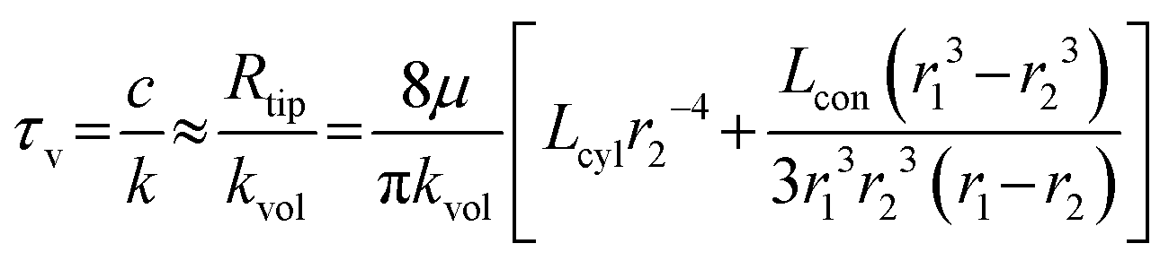
The analysis shows that the inertial time constant τd is influenced by both the effective fluid mass in the main flow channel and the stiffness of the deformation segment. Specifically, τd increases with the channel length and fluid density but decreases with the channel radius and the effective stiffness of the deformation segment. In addition, the viscous time constant τv is mainly influenced by the hydraulic resistance of the channels in the probe tip, which consists of a conical segment and a short cylindrical segment. The viscous time constant τv increases with the lengths of the conical and cylindrical segments and decreases sharply with the outlet radius at the probe tip. This strong dependence arises from the fourth-power relationship between the hydraulic resistance and the outlet radius.
In our previous micropipette studies, the models used to analyze the factors influencing the response time of the system were based on impedance formulations and neglected the inertia term.34 In this work, the model incorporates fluid inertia, hydraulic resistance, and elastic deformation, thereby providing deeper guidance for structural optimization. To identify the dominant time constant, we substituted the structural and material parameters into the damping ratio expression. The calculated damping ratio (ζ ≈ 0.3–0.4) indicates that the system operates in a slightly underdamped regime, where inertial and viscous contributions are of the same order. The liquid switching time is defined as the duration for the concentration to reach 63.2% of its total change, which mainly reflects the initial stage of the concentration increase. Although the present system exhibits second-order dynamics, we adopt this 63.2% criterion as an operational time constant to enable direct comparison with prior studies that report response times using the same definition.17 In this initial period, the displacement of the switched solution (injected solution) is largely influenced by inertial effects. As a result, the inertial time constant τd contributes most to the response time of the system.
Based on the above analysis, several structural adjustments were made. To reduce the response time of the system and thereby shorten the liquid switching time, the main channel was reduced in length, and stiffer glass capillaries were used for solution delivery. A thicker and stiffer silicone tube was also selected for the deformation segment to increase its effective stiffness. To further reduce the effective deformation length of the deformation segment, axial preload was applied to the glass capillaries before fixation, which shortened the distance between the two glass capillaries' end faces inside the silicone tube (Fig. 4). During tube connection, a minimal amount of adhesive was used to prevent it from entering the main channel and narrowing the flow path. These modifications improved the liquid switching time to the millisecond scale.
 | ||
| Fig. 4 Representative example showing that preloading shortens the effective deformation length of the silicone tube (deformation segment), as indicated by the inset images above the liquid-switching module schematics, thereby reducing the liquid switching time from 9 ms to 2 ms. | ||
Liquid switching range
Theoretically, continuous and low-speed injection–aspiration through the liquid switching module can generate a confined flow field on the chip surface. This confinement arises from the hydrodynamic balance between the injection and aspiration streams in the parallel gap between the probe and the chip surface, as reported previously.35 However, it has not been experimentally verified whether the synchronized injection–aspiration used in this study can also achieve localized liquid switching. To examine this, a droplet containing polystyrene (PS) microspheres (∼5 μm in diameter) was placed on the chip surface. When synchronized opposite-phase voltages were applied to the two piezo-stacks, solution was injected through one channel and aspirated through the other at the 3D-printed probe tip, generating a local flow field above the chip surface. Microspheres suspended in this region were displaced by the resulting hydrodynamic forces, and their motion indicated the local flow direction. The trajectories of the particles were visualized by superimposing sequential image frames, as shown in Fig. 3G, where the flow path from the inlet of the 3D-printed probe to the outlet is clearly observed.To evaluate the liquid switching region, the solution on the chip surface was colorless and transparent, and Rhodamine B was added to the switched solution. The spatial boundary of the liquid switching was determined by comparing the grayscale level distribution in images acquired before and after liquid switching, as shown in Fig. 3H. Although repeated experiments led to adhesion of microspheres and Rhodamine staining on the probe surface, which reduced image clarity, the approximate extent of the liquid switching region could still be identified. The results confirm that the synchronized injection–aspiration generates a flow field whose boundary remains far from the sensing beam. As a result, the influence of liquid switching on force measurement is effectively reduced, the residual disturbance was estimated to be on the order of 10−2 μm, remaining within the baseline noise level of the sensor.26,27
Liquid switching and measurement steps
The liquid switching and cell measurement process consists of the following steps (Video S2): first, the microfluidic chip is fixed onto the microscope stage. The original solution (hyperosmotic solution containing cells) is then dropped onto the open chip, and optical tweezers are used to position a single cell between the on-chip probes. A preloading force is applied to the cell by actuating the external piezo-actuator. Subsequently, the original solution and the switching solution (the hypoosmotic solution containing Rhodamine B) are injected into two separate channels of the liquid switching module, and the tip of the 3D-printed probe is positioned above the on-chip probes using a 3D manipulator (Fig. 3I). As introduced above, the liquid switching time is determined by the response time of the system and the diffusion of the solutions. To reduce the delay caused by diffusion, we use a pre-positioning and one-click return operation so that the probe tip can quickly reach the target position, thereby shortening the contact time between the two solutions. Even after reducing the contact time, diffusion still broadens the contact interface and increases the volume required for the complete solution change. Therefore, the switched solution volume was set to be much larger than this characteristic volume to ensure complete replacement of the original solution around target cells. A rising trapezoidal waveform (0–30 V) was applied to the piezo-stack at the injection side while a synchronized falling trapezoidal waveform (10–0 V) was applied to the aspiration side, both with a rise time of 1 ms. This achieves a rapid change in the microenvironment surrounding the cell on the chip, transitioning from the original solution to the switching solution (Fig. 3J). During this process, the cell's volume and Young's modulus dynamically change. By monitoring the displacement of on-chip probes, the dynamic changes in cell size and reactive force can be obtained. Additionally, the timing of the liquid switching is determined by analyzing the grayscale level changes. Finally, the piezo-actuators are driven to release the cell.36Results and discussion
Young's modulus of WT and ΔmscL Synechocystis cells
In this study, we used the model cyanobacterium Synechocystis sp. PCC 6803, including the wild-type strain and the MscL-deficient mutant (ΔmscL) provided by Tohoku University. The procedures for cell preparation are shown in Fig. S3. As introduced above, the reactive force on the single cell was obtained from the displacement of the sensing probe measured using the moiré fringe method, and the cell deformation was determined from the relative displacement between the on-chip probes. The Hertz model provides the force–indentation relation for elastic contact between the probe and the cell.37,38 Because the Hertz model applies only to small elastic deformations, we used the initial 10% of the deformation data to calculate the Young's modulus. The detailed force measurement & calibration method and cell culture & preparation process are provided in the SI.It should be emphasized that the present loading configuration differs fundamentally from sharp-tip AFM indentation commonly modelled as a pressurized elastic shell.39 In our system, single cells are compressed symmetrically between two flat on-chip probes, resulting in global deformation of the entire cell rather than localized membrane bending. As demonstrated in our previous work, flat compression under small deformation (<10%) provides a measurement of whole-cell stiffness under defined boundary conditions.24 In contrast, sharp-tip indentation primarily probes local surface stiffness and can yield substantially different Young's modulus values depending on the model.40 Therefore, the Young's modulus reported here should be understood within the context of flat whole-cell compression and interpreted when comparing WT and ΔmscL cells under identical loading conditions.
Fig. 5A shows two representative fitted curves illustrating the relationship between the relative deformation of a single cell and the reactive force under hypoosmotic and hyperosmotic conditions, depicted in pink and blue, respectively. The Young's modulus of individual cells was obtained from these fitted curves. The horizontal axis represents the relative deformation, defined as the ratio of single cell deformation to the initial cell diameter. This dimensionless quantity describes the normalized extent of cell compression during loading. We further statistically analyzed the Young's modulus of WT and ΔmscL cells under hypoosmotic and hyperosmotic conditions (Fig. 5B), with at least 15 individual cells measured for each group. The results showed that, for both WT and ΔmscL cells, the Young's modulus was significantly higher under hypoosmotic conditions than under hyperosmotic conditions (two-tailed Welch's t-test: WT (hyperosmotic vs. hypoosmotic), p = 0.022; ΔmscL (hyperosmotic vs. hypoosmotic), p = 0.023). Under the same osmotic condition, ΔmscL cells consistently exhibited a higher Young's modulus than WT cells. The difference between the two strains was more pronounced under hyperosmotic conditions (p = 0.049), indicating that MS channels are involved in the mechanical adaptation of cells to osmotic stress. Under hypoosmotic conditions, the difference was not statistically significant (p = 0.496), although the mean modulus of ΔmscL cells was still higher than that of WT cells. One possible explanation is that, in the absence of MscL, the cells already maintain a relatively high stiffness under hyperosmotic conditions, so the additional increase in stiffness during hypoosmotic swelling is limited and more easily masked by cell-to-cell variability. In contrast, WT cells show a larger change in Young's modulus between the two conditions.
 | ||
| Fig. 5 Young's modulus of Synechocystis cells under different osmotic conditions. (A) Representative force–deformation curves of single WT cells fitted using the Hertzian model under hypoosmotic (pink triangles) and hyperosmotic (blue circles) conditions. (B) Statistical analysis of the Young's modulus of WT and ΔmscL cells (n ≥ 15 for each group) under the two osmotic conditions. The Young's modulus of both cell types increased under hypoosmotic conditions, and ΔmscL cells exhibited higher Young's modulus values than WT cells under the same osmotic conditions. | ||
It should be noted that the Young's modulus analyzed here reflects the steady-state mechanical properties of cells under hypoosmotic and hyperosmotic conditions. Under these steady-state osmotic conditions, MscL in WT cells are not expected to be actively gated. Therefore, the higher Young's modulus observed for ΔmscL cells under hyperosmotic conditions does not indicate MscL activity, but rather reflects a baseline mechanical state associated with deletion of MscL. Similar differences in Young's modulus between WT and ΔmscL cells under hyperosmotic conditions were also observed in our previous work.24
Transient response of a single cell during osmotic downshock
During osmotic downshock, cells undergo rapid volume change and large deformation, under which classical contact mechanics models are no longer strictly applicable. Therefore, time-resolved Young's modulus is not used to describe the transient response. Instead, the transient mechanical behavior is characterized by deformation dynamics, including response time, reactive force, and deformation rates of cells. It should be noted that the present measurements provide whole-cell mechanical phenotypes and do not directly read out MscL gating events. Therefore, the involvement of MS channels discussed below is inferred from the differences between WT and ΔmscL cells measured under identical liquid switching and mechanical loading conditions.As described above, the hypoosmotic solution containing Rhodamine B was introduced into the switched solution, while the chip surface was initially filled with the original hyperosmotic solution. The cell was held between on-chip probes and immersed in the hyperosmotic environment. At time tL, the 3D-printed probe simultaneously injected and withdrew the solution, causing a rapid change in the extracellular environment from the hyperosmotic to the Rhodamine B-labeled hypoosmotic solution. The timing of the liquid switching was determined by analyzing the grayscale level within the detection region, while the cell's transient mechanical response to osmotic shock was evaluated by measuring the relative displacement of the sensing probe.
An example is shown in Fig. 6. The upper panel shows the temporal change in grayscale level within the detection region, which reflects the variation in solution concentration during liquid switching. The lower panel shows the normalized cell size as a function of time, where “size of cell” is defined as the ratio of the instantaneous cell width measured along the compression direction to its initial diameter. The same trace in the lower panel is displayed with dual y-axes. The right axis indicates the normalized cell size, and the left axis indicates the corresponding reactive force obtained by linear scaling. During liquid switching, the pushing probe remains stationary. Hence, as the cell deforms, the sensing probe is displaced, and a corresponding reactive force is measured, leading to a linear correspondence between the two axes.
 | ||
| Fig. 6 An example of transient deformation of a single Synechocystis cell during osmotic downshock. The upper panel shows the temporal variation of grayscale level within the detection region, reflecting the concentration change during high-speed liquid switching. The lower panel shows the normalized size of cell (the ratio of the instantaneous cell width measured along the compression direction to its initial diameter) and reactive force versus time. The synchronous onset of the grayscale level change and cell deformation confirmed that the liquid switching time was shorter than the cell's response time. | ||
The time constant τ is defined as the time required for the signal to reach approximately 63.2% of its final value, and is used to quantitatively characterize both the liquid switching time and the response time of cells. By comparing the two curves, we found that the decrease in grayscale level occurred almost simultaneously with the onset of cellular deformation but finished much earlier. This shows that the liquid switching time was much shorter than the cell's response time to osmotic shock. This means that the measured mechanical response mainly reflects the cell's intrinsic response to osmotic stress under millisecond-scale liquid switching.
The size–time curve shows two distinct parts. Before the peak, the response rises in a nonlinear manner and reaches the maximum within a few milliseconds after the onset of osmotic downshock. This nonlinear rise is expected because the osmotic driving force changes with time: as the cell volume increases, intracellular solutes are diluted and the effective osmotic gradient decreases. After the peak, the signal decreases continuously, with a fast initial decrease followed by a slower relaxation. This behaviour is consistent with a rapid release of membrane tension after the peak, where MS channel opening under high tension may play a role. The later slower relaxation may involve slower recovery processes, such as osmotic re-equilibration, intracellular solute redistribution, and mechanical relaxation under compression. The maximum expansion before shrinkage is defined as the expansion rate Lexp, representing the relative increase in cell size compared with the initial diameter. The reductions in normalized cell size within 100 ms and 1 s after the peak are defined as the short-term shrinkage rate Ls1 and long-term shrinkage rate Ls2, respectively (Fig. 6). Here, 100 ms and 1 s after the peak are used as fixed reference time points to describe the early and late parts of the post-peak decrease for comparison across cells. They are not intended to define a uniquely determined transition time of the curve or to represent channel gating kinetics.
Although Fig. 6 mainly presents the temporal change in cell size, this size–time response is only physically meaningful when the cell is mechanically constrained. For non-adherent cells, millisecond-scale liquid switching inevitably induces transient flow, which would displace the cell in the absence of on-chip probes. Holding the cell between the on-chip probes can ensure that the observed size change originates from cellular deformation rather than flow-induced motion. Moreover, the force sensing provides a well-defined mechanical loading condition during transient measurements, which is necessary for quantitative comparison of deformation dynamics.
Statistical comparison of transient responses between WT and ΔmscL cells
We statistically analyzed the response times of WT and ΔmscL cells under different liquid switching times, with no fewer than 20 cells measured in each group. And cells were collected from more than ten independent liquid culture batches (Fig. 7). Benefiting from the integrated system capable of millisecond-scale liquid switching and synchronized force detection, this study for the first time statistically compared the transient mechanical response of single WT and ΔmscL cells under compression. Linear fitting of the data indicated that the response times of both strains increased with longer liquid switching times (Fig. 7A). It should be noted that we added the linear fit only as an empirical guide to visualize the overall trend within the tested switching time range; it is not intended as a mechanistic model. | ||
| Fig. 7 Comparison of the response times between WT and ΔmscL cells under different liquid switching times. (A) Relationship between the liquid switching time and response time for WT and ΔmscL cells. (B) Box plots showing the distributions of liquid switching time and response time for both strains. (C) Reactive force of WT and ΔmscL cells under high-speed liquid switching. (D) Statistical results of relative cell deformation parameters (expansion rate Lexp, short-term shrinkage rate Ls1, and long-term shrinkage rate Ls2) under high-speed liquid switching. | ||
Recent molecular dynamics simulations have shown that MscL opens faster and reaches a larger pore size when the membrane tension is higher, as the energy barrier for gating decreases with increasing tension.41 Therefore, rapid osmotic transitions that produce higher transient membrane tension are likely to facilitate quicker MscL activation, which explains the shorter response time observed in WT cells under high-speed liquid switching.
Under comparable switching conditions, the response times showed substantial overlap across individual cells, while the group mean was higher for WT than for ΔmscL. To summarize the distributions, we compared the distributions of response times using box plots (Fig. 7B). The mean liquid switching time was 3.43 ± 1.66 ms for WT cells and 3.08 ± 2.27 ms for ΔmscL cells, showing no significant difference between the two groups (p = 0.576), indicating that the switching conditions were comparable for both strains. In contrast, the mean response time was 13.15 ± 5.12 ms for WT cells and 9.41 ± 5.48 ms for ΔmscL cells (p = 0.030).
The slower mechanical response observed in WT cells may reflect the contribution of MS channels during liquid switching under continuous compression. In our setup, each cell was held between two on-chip probes while the external solution was rapidly replaced to induce osmotic downshock under a fixed mechanical constraint. The different responses between WT and ΔmscL cells are consistent with a contribution from MscL in relieving membrane tension under high tension. In WT cells, MscL transiently opened under the increased membrane tension, releasing intracellular solutes and partially relieving membrane stress. This transient tension release moderated the buildup of membrane strain, resulting in a delayed deformation response detected by the on-chip probes. In contrast, ΔmscL cells lack this high-threshold release mechanism and mainly rely on low-threshold channels such as MscS, which can be activated more easily under moderate tension and subsequently inactivate as tension relaxes. Previous studies reported that MscS is activated at 5–7 mN m−1 and exhibits adaptive inactivation, whereas MscL activates near 10–14 mN m−1 and remains open under sustained stress.16,42 These results suggest that MscL serves as a mechanical buffer to regulate membrane tension and maintain mechanical stability during rapid osmotic transitions under external compression.
To further understand how the presence or absence of MscL affects the mechanical response of cells beyond the response time, we analyzed the deformation behavior during and after liquid switching, including the reactive force, the expansion rate Lexp, and the short-term shrinkage rates Ls1 and long-term shrinkage rates Ls2 (Fig. 7C and D).
As shown in Fig. 7C, the mean reactive force was 0.27 ± 0.08 μN for WT cells and 0.28 ± 0.05 μN for ΔmscL cells, indicating that the applied mechanical compression was nearly identical between the two strains. Under this condition, ΔmscL cells showed a larger expansion rate than WT cells (p = 0.024), suggesting that the presence of MscL helps limit excessive cell deformation during osmotic stress. Although the difference in shrinkage rates was not statistically significant (Ls1, p = 0.226; Ls2, p = 0.610), WT cells tended to shrink more slowly than ΔmscL cells (Fig. 7D).
In addition, this trend is opposite to our previous results obtained under second-scale switching in a closed chip, where WT cells exhibited faster shrinkage after expansion.26 In our previous study, the slow liquid switching extended the osmotic change period while the cells remained compressed between the on-chip probes. Under these conditions, the membrane tension of WT cells may have remained above the activation threshold of MscL for a longer period, which could keep MscL active and promote continued solute release. As a result, WT cells showed a larger shrinkage after expansion than ΔmscL cells.
In this work, the liquid switching module operated more than 100 times faster than our previous setup. During such a rapid downshock, the sudden rise in membrane tension could exceed the release capacity of the remaining MS channels in ΔmscL cells. In some cells, the membrane tension may have reached the rupture limit before it could be relieved, leading to partial rupture and cytoplasmic leakage, which resulted in stronger shrinkage. In contrast, WT cells have the MscL, which may facilitate tension relief under strong downshock and thereby reduce the likelihood of rupture. This interpretation is consistent with previous reports that osmotic downshock can cause membrane rupture.22,43
Nevertheless, the difference in post-peak shrinkage between WT and ΔmscL was not significant. These post-peak shrinkage values vary substantially across cells, likely due to differences in the initial cell condition and small variations in probe contact. With this level of variability, a small difference between WT and ΔmscL can be difficult to detect. In addition, Ls1 and Ls2 are taken from the latter part of the response. During this period, the osmotic driving force weakens and time-dependent mechanical relaxation of the cell envelope becomes more influential; other ion-transport pathways may also contribute on this time scale, so the difference between WT and ΔmscL is less pronounced in Ls1 and Ls2 than in Lexp. Occasional rupture in ΔmscL cells also increases the scatter.10,15
Although this work focuses on MS channels in cyanobacteria, the integrated millisecond liquid switching and on-chip force sensing strategy is general and may be adapted to other single-cell studies and potentially to food and environmental applications where microfluidic platforms and related microscale analytical approaches have been explored for controlled handling and rapid assays.44–47
Conclusions
In this study, we developed a microfluidic system that integrates high-speed liquid switching with on-chip force sensing to measure single-cell mechanical responses under osmotic downshock. The system achieved localized liquid switching on a millisecond scale. This allowed direct detection of the transient mechanical response of single cells under controlled extracellular conditions.We measured the Young's modulus, response time, expansion rate, and shrinkage rate of WT and ΔmscL cells. The Young's modulus of both strains increased in hypoosmotic conditions compared with hyperosmotic conditions. Compared with ΔmscL cells, WT cells exhibited a longer response time, a smaller expansion rate, and a slower shrinkage rate under high-speed liquid switching. These results suggest that MscL may contribute to limiting excessive deformation during osmotic downshock under our loading configuration, consistent with a tension-buffering role inferred from the WT and ΔmscL cells comparison.
This work provides an experimental approach for analyzing transient cellular mechanical responses under rapid environmental changes. The ability to achieve millisecond-scale liquid switching with synchronized force measurement provides a foundation for understanding how mechanosensitive channels regulate cellular mechanics and maintain mechanical homeostasis. The platform can be further applied to various cell types and microenvironmental conditions, offering broad potential for mechanobiological research and related applications.
In future work, we will pursue simplification and tighter integration by leveraging 3D-printed microfluidic chips and integrated interfaces to reduce dependence on external subsystems.
Conflicts of interest
There are no conflicts to declare.Data availability
The data supporting this article have been included as part of the paper and the supplementary information (SI).Supplementary information: equipment, chip fabrication, force detection and calibration, response time of the liquid switching module, and cell culture & preparation (PDF); Video S1: mechanical property measurement of a single cell using a robot-integrated microfluidic chip (MP4); Video S2: an example of single-cell compression and liquid switching process (MP4). See DOI: https://doi.org/10.1039/d6lc00004e.
Acknowledgements
This work was partially supported by Grants-in-Aid for Scientific Research from the Ministry of Education, Culture, Sports, Science, and Technology (18H03762 and 21H04543 to F. A. and N. U.) and the Jiangsu Provincial Natural Science Foundation of China (Grant BK20250842). We thank Prof. Hisataka Maruyama of Nagoya University, Dr. Shingo Kaneko of the University of Tokyo, and Prof. Hirotaka Sugiura of the University of Tokyo for their assistance with device fabrication and instrument operation.Notes and references
- Y. Zhang, C. Daday, R. Gu, C. Cox, B. Martinac, B. de Groot and T. Walz, Nature, 2021, 590, 509–514 CrossRef CAS PubMed.
- M. Baghdadi, R. Houtekamer, L. Perrin, A. Rao-Bhatia, M. Whelen, L. Decker, M. Bergert, C. Pérez-Gonzàlez, R. Bouras, G. Gropplero, A. Loe, A. Afkhami-Poostchi, X. Chen, X. Huang, S. Descroix, J. Wrana, A. Diz-Muñoz, M. Gloerich, A. Ayyaz, D. Vignjevic and T. Kim, Science, 2024, 386, eadj7615 CrossRef CAS PubMed.
- L. Salameh, S. Bitzenhofer, I. Hanganu-Opatz, M. Dutschmann and V. Egger, Science, 2024, 383, eadk8511 CrossRef PubMed.
- K. Bera, A. Kiepas, I. Godet, Y. Li, P. Mehta, B. Ifemembi, C. Paul, A. Sen, S. Serra, K. Stoletov, J. Tao, G. Shatkin, S. Lee, Y. Zhang, A. Boen, P. Mistriotis, D. Gilkes, J. Lewis, C. Fan, A. Feinberg, M. Valverde, S. Sun and K. Konstantopoulos, Nature, 2022, 611, 365–373 CrossRef CAS PubMed.
- K. Morishita, K. Watanabe and H. Ichijo, Cancer Sci., 2019, 110, 2337–2347 CrossRef CAS PubMed.
- T. Zavřel, P. Očenášová and J. Červený, PLoS One, 2017, 12, e0189130 CrossRef PubMed.
- P. Sánchez-Baracaldo and T. Cardona, New Phytol., 2020, 225, 1440–1446 CrossRef PubMed.
- S. Lucius and M. Hagemann, Front. Plant Sci., 2024, 15, 1417680 CrossRef CAS PubMed.
- Y. Kato, K. Kamasaka, M. Matsuda, H. Koizumi, R. Ohbayashi, H. Ashida, A. Kondo and T. Hasunuma, J. Biosci. Bioeng., 2025, 139, 187–193 CrossRef CAS PubMed.
- E. Perozo, D. Cortes, P. Sompornpisut, A. Kloda and B. Martinac, Nature, 2002, 418, 942–948 CrossRef CAS PubMed.
- R. Buda, Y. Liu, J. Yang, S. Hegde, K. Stevenson, F. Bai and T. Pilizota, Proc. Natl. Acad. Sci. U. S. A., 2016, 113, E5838–E5846 CrossRef CAS PubMed.
- Y. Sawada, T. Nomura, B. Martinac and M. Sokabe, Front. Chem., 2023, 11, 1175443 CrossRef CAS PubMed.
- R. Wray, J. Wang, P. Blount and I. Iscla, Antibiotics, 2022, 11, 970 CrossRef CAS PubMed.
- J. Najem, M. Dunlap, I. Rowe, E. Freeman, J. Grant, S. Sukharev and D. Leo, Sci. Rep., 2015, 5, 1–11 Search PubMed.
- M. Andersson, G. Okeyo, D. Wilson, H. Keizer, P. Moe, P. Blount, D. Fine, A. Dodabalapur and R. Duran, Biosens. Bioelectron., 2008, 23, 919–923 CrossRef CAS PubMed.
- K. Ramsey, M. Britt, J. Maramba, B. Ushijima, E. Moller, A. Anishkin, C. Häse and S. Sukharev, iScience, 2024, 27, 110001 CrossRef CAS PubMed.
- K. Nanatani, T. Shijuku, M. Akai, Y. Yukutake, M. Yasui, S. Hamamoto, K. Onai, M. Morishita, M. Ishiura and N. Uozumi, Channels, 2013, 7, 238–242 CrossRef CAS PubMed.
- X. Zhang, F. Bian, Y. Wang, L. Hu, N. Yang and H. Mao, Foods, 2022, 11, 3462 CrossRef CAS PubMed.
- S. Gebreyesus, A. Siyal, R. Kitata, E. Chen, B. Enkhbayar, T. Angata, K. Lin, Y. Chen and H. Tu, Nat. Commun., 2022, 13, 37 CrossRef CAS PubMed.
- M. Saito, F. Arai, Y. Yamanishi and S. Sakuma, Proc. Natl. Acad. Sci. U. S. A., 2024, 121, e2306182121 CrossRef CAS PubMed.
- M. Hassan, X. Yi, M. Zareef, H. Li and Q. Chen, Trends Food Sci. Technol., 2023, 142, 104230 CrossRef CAS.
- S. Kaneko, S. Hirotaka, M. Tsujii, H. Maruyama, N. Uozumi and F. Arai, Lab Chip, 2024, 24, 281–291 RSC.
- Q. Zhang, S. Feng, L. Lin, S. Mao and J. Lin, Chem. Soc. Rev., 2021, 50, 5333–5348 RSC.
- D. Chang, S. Sakuma, K. Kera, N. Uozumi and F. Arai, Lab Chip, 2018, 18, 1241–1249 RSC.
- Y. Takayama, G. Perret, M. Kumemura, M. Ataka, S. Meignan, S. Karsten, H. Fujita, D. Collard, C. Lagadec and M. Tarhan, Micromachines, 2018, 9, 275 CrossRef PubMed.
- X. Du, D. Chang, S. Kaneko, H. Maruyama, H. Sugiura, M. Tsujii, N. Uozumi and F. Arai, Engineering, 2023, 24, 94–101 CrossRef.
- X. Du, S. Kaneko, H. Maruyama, H. Sugiura, M. Tsujii, N. Uozumi and F. Arai, Micromachines, 2023, 14, 1210 CrossRef PubMed.
- Y. Hao, S. Cheng, Y. Tanaka, Y. Hosokawa, Y. Yalikun and M. Li, Biotechnol. Adv., 2020, 45, 107648 CrossRef CAS PubMed.
- H. Sugiura, S. Sakuma, M. Kaneko and F. Arai, Micromachines, 2015, 6, 660–673 CrossRef.
- P. Liu, Q. Huang, M. Khan, N. Xu, H. Yao and J. Lin, Anal. Chem., 2020, 92, 7900–7906 CrossRef CAS PubMed.
- E. Delamarche, I. Pereiro, A. Kashyap and G. Kaigala, Langmuir, 2021, 37, 9637–9651 CrossRef CAS PubMed.
- A. Rane, S. Tate, J. Sumey, Q. Zhong, H. Zong, B. Purow, S. Caliari and N. Swami, ACS Biomater. Sci. Eng., 2024, 10, 3470–3477 CrossRef CAS PubMed.
- N. Ostromohov, M. Bercovici and G. Kaigala, Lab Chip, 2016, 16, 3015–3032 RSC.
- Y. Kasai, S. Sakuma and F. Arai, Microfluid. Nanofluid., 2019, 23, 1–9 CrossRef.
- D. Taylor, P. Mathur, P. Renaud and G. Kaigala, Lab Chip, 2022, 22, 1415–1437 RSC.
- X. Du, S. Kaneko, H. Maruyama, H. Sugiura and F. Arai, in 36th IEEE International Conference on Micro Electro Mechanical Systems (MEMS), Munich, Germany, 2023 Search PubMed.
- H. Hertz, J. Reine Angew. Math., 1881, 92, 156–171 Search PubMed.
- K. L. Johnson, Contact Mechanics, Cambridge University Press, Cambridge, UK, 1987 Search PubMed.
- D. Vella, A. Ajdari, A. Vaziri and A. Boudaoud, J. R. Soc., Interface, 2012, 9, 448–455 CrossRef CAS PubMed.
- D. Chang, T. Hirate, C. Uehara, H. Maruyama, N. Uozumi and F. Arai, Microsc. Microanal., 2021, 27, 392–399 CrossRef CAS PubMed.
- T. Rajeshwar, A. Anishkin, S. Sukharev and J. Vanegas, Biophys. J., 2021, 120, 232–242 CrossRef PubMed.
- E. Moller, M. Britt, A. Schams, H. Cetuk, A. Anishkin and S. Sukharev, J. Gen. Physiol., 2023, 155, e202213168 CrossRef CAS PubMed.
- U. Çetiner, I. Rowe, A. Schams, C. Mayhew, D. Rubin, A. Anishkin and S. Sukharev, J. Gen. Physiol., 2017, 149, 595–609 CrossRef PubMed.
- J. Wang, F. Jing, Y. Zhao, Z. You, A. Zhang and S. Qin, Trends Pharmacol. Sci., 2025, 46, 752–770 CrossRef CAS PubMed.
- H. Jayan, R. Zhou, Y. Zheng, S. Xue, L. Yin, H. R. El-Seedi, X. Zou and Z. Guo, Food Chem., 2025, 471, 142800 CrossRef CAS PubMed.
- W. Yang, L. Cao, H. Lu, Y. Huang, W. Yang, Y. Cai, S. Li, S. Li, J. Zhao and W. Xu, J. Food Sci., 2024, 89, 5980–5992 CrossRef CAS PubMed.
- S. Y.-S. S. Adade, H. Lin, N. A. N. Johnson, X. Nunekpeku, J. H. Aheto, J.-N. Ekumah, B. A. Kwadzokpui, E. Teye, W. Ahmad and Q. Chen, Trends Food Sci. Technol., 2025, 156, 104851 CrossRef CAS.
| This journal is © The Royal Society of Chemistry 2026 |