
 Open Access Article
 This Open Access Article is licensed under a Creative Commons Attribution-Non Commercial 3.0 Unported Licence
Clog-free all-aqueous microfluidic fabrication of hydrogel microfibers governed by a universal scaling law
Jinchang
Zhu†
a,
Yi
He†
d,
Jing
Wang†
b,
Isabella
Powell
b,
Pu
Zhang
e,
Anthony
Ouertani
b,
Yong
Wang
d and
Li-Heng
Cai
 *abc
*abc
aSoft Biomatter Laboratory, Department of Materials Science and Engineering, University of Virginia, Charlottesville, VA 22904, USA. E-mail: liheng.cai@virginia.edu
bDepartment of Chemical Engineering, University of Virginia, Charlottesville, VA 22904, USA
cDepartment of Biomedical Engineering, University of Virginia, Charlottesville, VA 22904, USA
dDepartment of Surgery, University of Virginia, Charlottesville, VA 22904, USA
eDepartment of Mechanical and Aerospace Engineering, University of Virginia, Charlottesville, VA 22904, USA
First published on 26th November 2025
Abstract
Hydrogel microfibers provide a versatile platform for cell encapsulation and tissue engineering, but their fabrication typically involves harsh or clog-prone processes that limit cytocompatibility or scalability. Here, we report a clog-free, all-aqueous water-in-water-in-water microfluidic approach for continuous and cytocompatible fabrication of hydrogel microfibers. This approach uses immiscible aqueous polymer solutions to enable fiber formation and controlled crosslinking without organic solvents and rapid solidification, preventing channel clogging during continuous operation. Using alginate as a model biomaterial, we generate meter-long microfibers that can be spun into macroscopic films. Systematic experiments and laminar flow modeling reveal a universal scaling law,  , showing that the fiber diameter Df depends solely on the collection capillary diameter Dc and the ratio of inner flow rate Qi to the total flow rate of the middle and outer phases Qsum. Finally, we demonstrate encapsulation of pancreatic β-cells, which retain glucose-responsive insulin secretion comparable to that of unencapsulated cells. This work establishes the physical basis of all-aqueous microfiber fabrication and provides a robust, scalable, and cytocompatible approach for cell encapsulation.
Introduction
Encapsulating cells in a thin layer of hydrogel allows for mimicking in vivo microenvironment, which is essential for engineering complex tissue mimics1 and delivery of therapeutic cells.2–4 Compared to spherical microparticles,5,6 one-dimensional (1D) microfibers emulate the geometry of important biological tissues such as blood vessels.7 Moreover, they are relatively easy to handle and sometimes can be used to create complex three-dimensional (3D) structures without sacrificing the advantages of microencapsulation. These advantages enable a wide range of biomedical applications for hydrogel microfiber including vascular tissue engineering, islet transplantation, and nerve regeneration.8–10The fabrication of hydrogel microfibers typically involves two steps: generating a continuous thread of a polymer or oligomer solution and solidifying it into stable fiber. For instance, in wet spinning, a micronozzle extrudes prepolymer threads into a coagulation bath containing crosslinking agents, where the threads rapidly crosslink and solidify.11,12 In water-in-water (W/W) microfluidics, a microfluidic chip generates a prepolymer thread sheathed by a surrounding flow. Because both the dispersion and the continuous phases are aqueous, the prepolymer thread is miscible with the sheath flow. Thus, the prepolymer thread must solidify rapidly upon contact with crosslinking agents in the sheath phase or upon UV exposure.8,13–19 Because of their mild and cell-friendly conditions, both wet spinning and W/W microfluidics are well suited for fabricating cell-laden hydrogel microfibers. Common examples include alginate fibers crosslinked with calcium ions,8,13–17 and poly(ethylene glycol) (PEG) or gelatin methacrylate (GelMA) hydrogel fibers crosslinked via photopolymerization.18,20 However, in these approaches, prepolymer solidification often clogs micronozzles or microchannels, as rapid crosslinking inevitably occurs near the thread outlet, disrupting continuous and scalable fabrication. Alternatively, electrospinning uses electric force to draw a charged thread of prepolymer solution that solidifies upon entering a coagulation bath. Although separating the nozzle and bath with an electric field mitigate clogging, the high voltages required, typically >10 kV,21,22 are undesirable for in situ cell encapsulation. These limitations highlight the need for a fully aqueous, clog-free, and cytocompatible approach to fabricate hydrogel microfibers without premature solidification.
Here, we report a clog-free, all-aqueous water-in-water-in-water (W/W/W) microfluidic approach for continuous and cytocompatible fabrication of hydrogel microfibers. The system consists of an inner biopolymer phase, a middle sheath phase, and an outer crosslinker phase. Unlike conventional W/W systems, fiber formation in W/W/W configuration relies on the immiscibility between the inner and the middle aqueous phases, each enriched with distinct solutes such as dextran and PEG, which spontaneously phase separate into two thermodynamically stable aqueous phases.23–26 The middle sheath enables controlled diffusion of crosslinkers from the outer phase, allowing controlled solidification of the inner phase without clogging, and thereby supporting stable, continuous operation. This approach yields meter-long hydrogel microfibers that can be further assembled into macroscopic films.
We further elucidate the physical principles governing fiber formation by systematically examining the dependence of fiber diameter on device geometry and flow rates. Combining experiments with a laminar flow model, we identify a universal scaling relation: 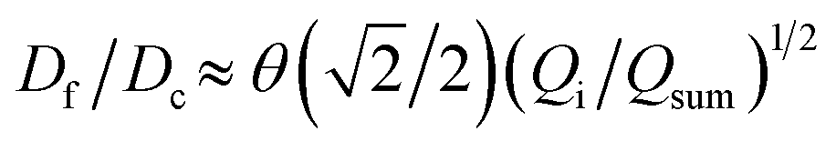 , where Df is the fiber diameter, Dc is the inner diameter of the collection capillary, Qi is the inner flow rate, and Qsum is the total flow rate of the middle and outer phases. This relationship shows that fiber diameter is independent of the inner capillary tip size and is determined solely by Dc and the flow rate ratio. Finally, as a proof of concept, we encapsulate pancreatic beta cells within the fibers and observe insulin secretion comparable to that of unencapsulated cells. Together, these results establish the physical basis of all-aqueous microfiber fabrication and demonstrate a scalable, cytocompatible route for cell encapsulation.
Results and discussion
We use a glass capillary microfluidic device to generate a transient W/W/W core–shell cylindrical fluid that serves as the template for the fabrication of alginate microfibers. The device comprises two tapered cylindrical capillaries that are inserted into the opposite ends of a square capillary (Fig. 1a). We use the left capillary to inject the inner phase consisting of 2.5% (w/v) sodium alginate and 15% (w/v) dextran with a viscosity of 44.5 mPa·s. The middle phase, 17% (w/v) PEG with a viscosity of 11.5 mPa·s, is injected from the left through the interstices between the left cylindrical capillary and the square capillary. The outer phase is injected from the right interstices; it is essentially the same PEG solution as the middle phase but contains 50 mM calcium chloride (CaCl2), which is enough for crosslinking alginate yet low enough without impairing cell viability.27 Importantly, the middle phase PEG solution and the inner phase dextran solution are immiscible yet with a small interfacial tension γ of ∼0.1 mNm−1. The small interfacial tension ensures that the inertial force from the inner liquid is on the same order of the surface tension force, as evidenced by the value of Weber number Win = ρindinu2in/γ ∼ O(1), in which ρin is the density of the inner liquid, din is the diameter of the inner capillary, and uin is the speed of the inner phase flow at the tip. At such conditions, the inner fluid forms a stable, cylindrical jet, as visualized in Fig. 1b. Subsequently, the cylindrical jet of alginate solution is solidified by the calcium ions that diffuses from the concentrated continuous outer phase, resulting in alginate microfibers, as visualized in Fig. 1c and shown by the optical microscopy images in Fig. 1d. | ||
| Fig. 1 All-aqueous continuous microfluidic fabrication of alginate hydrogel microfibers. (a) A schematic of the glass capillary microfluidic device for making alginate hydrogel microfibers. The device is operated in jetting regime to ensure a cylindrical fluid in the collection capillary. (b) An optical image of an alginate microfiber formed in the microfluidic device. Scale bar: 500 μm. (c) A meter-long alginate microfiber with a diameter of 70 μm made by the microfluidic device: (i) continuous fabrication process, (ii) final product, and (iii) a dry film made of woven microfibers. Scale bars: 1 cm. (d) Representative phase-contrast microscopy images of alginate microfibers with a diameter of (i) 70 μm and (ii) 140 μm. Scale bars: 100 μm. | ||
The existence of the middle phase is critical to the continuous production of alginate microfibers. Although the middle phase is essentially the same as the outer phase, it is the middle phase that prevents immediate contact between the inner alginate solution and the calcium ions at the entrance of the right capillary, thereby preventing the microfluidic device from clogging. For example, the time it takes for calcium ions to diffuse across the barrier formed by the middle phase is about td ≈ l2/D ≈ 40 s, in which D ≈ 10−9 m2 s−1 is the diffusion coefficient of Ca2+ in water, and l ≈ 200 μm is the thickness of the shell formed by the middle phase, as shown in Fig. 1b. This suggests that it takes at least 40 s to solidify the alginate; this is much longer than the time it takes for the alginate solution to pass the orifice of the collection capillary. Consequently, the separation from the middle phase ensures a continuous production of transient W/W/W core–shell cylindrical fluids that serve as templates for the fabrication of alginate microfibers. Indeed, this method enables the fabrication of meter-long alginate microfibers (Fig. 1c, i and ii) with a diameter from 70 to 140 μm (Fig. 1d). In practice, the system can operate for at least 30 min without clogging, producing a single fiber about 35 meters in length. During fabrication, the long fiber can be simultaneously woven into a macroscopic ribbon-like structure about 3 mm wide, demonstrating the scalability and robustness of the process (Fig. 1c, iii). Taken together, these results demonstrate all-aqueous continuous production of alginate microfibers.
The capability of a hydrogel fiber to encapsulate biologically active contents is determined by its smallest dimension – fiber diameter. Thus, we explore methods to control the fiber diameter Df. We identify two classes of parameters important to fiber diameter. One is the geometry of the microfluidic device that includes the tip diameter Di of the inner capillary and the diameter Dc of the collection capillary, and the other is the flow rates of the inner, middle, and outer phases, as illustrated in Fig. 2a. We start with exploring the effects of the inner phase flow rate Qi on the fiber diameter. To do so, we fix Di = 100 μm, Dc = 580 μm, the outer phase flow rate at Qo = 2.5 mL h−1, and the middle phase flow rate at Qm = 3.3 mL h−1, while increasing Qi from 0.1 to 0.7 mL h−1. Interestingly, at small Qi of 0.1 mL h−1, the fiber diameter is about half of the inner tip diameter with Df/Di ≈ 0.5 (left green circles, Fig. 2b). As Qi increases by 7 times from 0.1 to 0.7 mL h−1, the fiber diameter increases by about 3 times with Df/Di becoming 1.5 (right green circles, Fig. 2b). Yet, Df/Di increases nearly linearly with Qi, and a similar linear trend is observed for a smaller inner tip diameter Di = 70 μm (red squares, Fig. 2b). These results suggest that the fiber diameter can be precisely controlled within a few times of the inner tip diameter by changing the inner phase flow rate only.
 | ||
| Fig. 2 Dependencies of alginate microfiber diameter on the inner tip diameter and flow rates. (a) A schematic for the parameters involved in microfluidic fabrication of alginate microfibers. Qi, Qm, and Qo are the inner, middle, and outer phase flow rates, respectively. Di: inner tip diameter; Do: diameter of the outer capillary; Df: fiber diameter. (b) The dependence of Df/Di on the inner phase flow rate Qi. Fibers are fabricated at fixed Qo = 2.5 mL h−1 and Qm = 3.3 mL h−1 but various Qi. Red squares: Di = 70 μm; green circles: Di = 100 μm. (c) The dependence of Df/Di on the middle phase flow rate Qm. Fibers are fabricated at fixed Qo = 2.5 mL h−1, Qi = 0.36 mL h−1, and Di = 100 μm but various Qm. (d) The dependence of Df/Di on the outer phase flow rate Qo. Fibers are fabricated at fixed Qi = 0.36 mL h−1 and Qm = 3.3 mL h−1 but various Qo. Red squares: Di = 70 μm; green circles: Di = 100 μm. Error bar: standard deviation for n = 20. | ||
Next, we explore the dependence of fiber diameter on the middle and outer phase flow rates. We fix Di = 100 μm, Qi = 0.36 mL h−1, and Qo = 2.5 mL h−1 while changing the middle flow rate Qm only. As Qm increases from 3 to 10 mL h−1, Df/Di decreases slightly by 30% from 1 to 0.7 (Fig. 2c). Similarly, fixing the flow rates of the inner and middle phases respectively at Qi = 0.36 mL h−1 and Qm = 3.3 mL h−1 while increasing the outer phase flow rate from 3 to ∼6 mL h−1 results in a slight decrease of Df/Di from 0.91 to 0.75, as shown by the green circles in Fig. 2d. As the tip diameter decreases from 100 to 70 μm, the value of Df/Di becomes larger, but the relative change of Df/Di with respect to Qo is not much altered. Specifically, as Qo increases by four times from 2 to 8 mL h−1, Df/Di decreases by nearly 30% from 1.3 to 1 (red squares, Fig. 2d). Moreover, at relatively high outer phase flow rates with Qo > 6 mL h−1, the value of Df/Di becomes nearly a constant regardless of the outer phase flow rate. Nevertheless, the change of Df/Di achieved by altering the middle or the outer phase flow rates is about 30%, much less than the 300% achieved by changing the inner flow rate only (Fig. 2b). These results suggest that compared to the inner phase flow rate, the Df/Di is much less sensitive to the outer and middle phase flow rates.
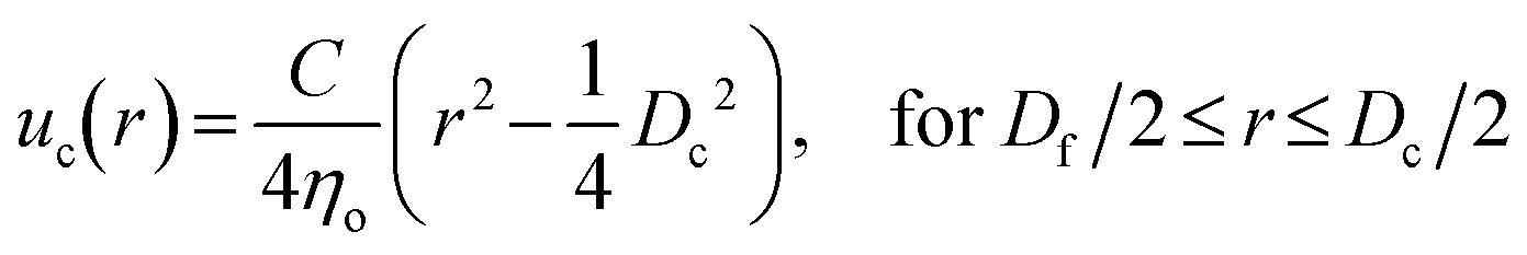
To better understand the dependence of fiber diameter on the flow rates, we consider the fluid mechanics associated with the microfluidic fabrication of alginate fibers. Unlike typical multiphase flows that are immiscible, in our approach the outer phase is essentially the same as the middle phase. Thus, the middle and outer phases together can be considered as a single phase with the total flow rate of Qsum = Qo + Qm. Consequently, the microfluidic system becomes a two-phase flow system, in which the dextran solution as the inner phase and the PEG solution as the outer phase form a co-centric flow through a cylindrical channel. Within the channel, the fluid velocity profile ![[u with combining right harpoon above (vector)]](https://www.rsc.org/images/entities/i_char_0075_20d1.gif) can be described by the Stokes–Navier equation, η∇2 = ∇P, where η is the fluid viscosity and ∇P is the pressure gradient along the channel. Because at each fabrication condition the flow rates are fixed, ∇P = C is a constant. Moreover, considering that the fluids form a stable, one-dimensional flow and the symmetry of the cylindrical capillary, the Stokes–Navier equation can be simplified in cylindrical coordinates:
can be described by the Stokes–Navier equation, η∇2 = ∇P, where η is the fluid viscosity and ∇P is the pressure gradient along the channel. Because at each fabrication condition the flow rates are fixed, ∇P = C is a constant. Moreover, considering that the fluids form a stable, one-dimensional flow and the symmetry of the cylindrical capillary, the Stokes–Navier equation can be simplified in cylindrical coordinates:
 | (1) |
 | (2) |
 | (3) |
 and
and  , which yield:
 | (4) |
 | (5) |
We test the prediction [eqn (5)] by plotting Df/Dc against Qi/Qsum, which collapses all data points regardless of tip diameter and various combinations of flow rates, as shown by the symbols in Fig. 3. Moreover, the best fit of the data, Df/Dc = (0.65 ± 0.7)(Qi/Qsum)1/2, agrees very well with the theoretical prediction (solid line in Fig. 3). Yet, we notice that there is a slight deviation of experimental data from theoretical prediction at low inner-phase flow rates. This may be attributed to an unstable co-flow and the extended diffusion time of calcium ions across the outer phase, resulting in a less controllable fiber diameter. Nevertheless, these results show that the fiber diameter can be precisely controlled by adjusting the flow rates; moreover, the absolute value of the fiber diameter can be further increased by using a collection capillary of larger diameters.
 | ||
Fig. 3 Universal dependence of fiber diameter on fabrication conditions. Df/Dc: the ratio between the fiber diameter and the inner diameter Dc = 580 μm of the collection capillary. Qi/(Qo + Qm): the ratio between the inner phase flow rate and the sum of the outer and middle phase flow rates. Solid line: best fit to the data: 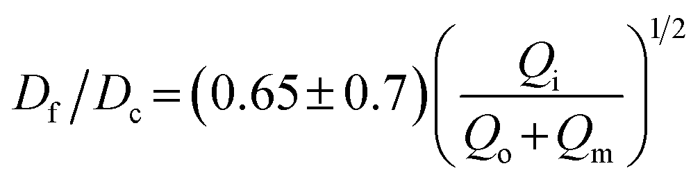 , which agrees very well with the theoretical prediction [eqn (5)]. Fibers are fabricated using an inner tip of diameter Di = 70 μm (empty symbols) and Di = 100 μm (filled symbols). The shapes of symbols represent various flow conditions in Fig. 2. Error bar: standard deviation for n = 20 for each condition. , which agrees very well with the theoretical prediction [eqn (5)]. Fibers are fabricated using an inner tip of diameter Di = 70 μm (empty symbols) and Di = 100 μm (filled symbols). The shapes of symbols represent various flow conditions in Fig. 2. Error bar: standard deviation for n = 20 for each condition. | ||
The microfibers are fabricated under aqueous conditions without the use of any biologically hazardous reagents. Moreover, alginate hydrogel is known to be porous for efficient transport of nutrients and biomolecules. Therefore, it should be possible to use these fibers to encapsulate cells without impairing their viability and activity. To demonstrate this possibility, we encapsulate MIN6 cells, a pancreatic beta cell line that retains glucose-stimulated insulin secretion response,28 and test their viability and function (see Materials and methods). After encapsulation, the cells maintain a viability greater than 80% in 48 h, a typical waiting time before transplantation in clinical settings,29,30 as shown by live/dead assay in Fig. 4a and b. The slight decrease in survival rate compared to naked cells is likely due to shear force-induced cell death during fabrication. Nevertheless, this survival rate is comparable to previously reported survival rates for MIN6 cells in alginate microcapsules and meets the standards for most applications.31,32
 | ||
| Fig. 4 Microfibers generated by the all-aqueous microfluidic system are cytocompatible and allow for responsive insulin release. (a) A representative fluorescence confocal microscopy image of microfibers encapsulated with MIN6 cells from live/dead assay. The image is generated by stacking two images of the same region of interest yet different focus planes. Scale bar: 100 μm. (b) Viability of naked and encapsulated MIN6 cells up to 48 h. (c) Glucose stimulation index of the naked and encapsulated MIN6 cells in response to high glucose. Error bar, standard deviation for n = 3 in (b) and (c). ***p < 0.001; n.s., not significant with p > 0.05 (Student's t-test). (d) Time-lapse confocal microscopy images showing the intracellular Ca2+ level of encapsulated MIN6 cells 60 min after being stimulated by high glucose. The signal intensity is defined as the ratio between the fluorescence intensity of Fura-2 calcium imaging dye activated at 340 and 380 nm light. Scale bar: 100 μm. (e) Normalized fluorescence intensity of encapsulated MIN6 cells in (d) and naked MIN6 cells. | ||
To test the function of encapsulated MIN6 cells, we perform static glucose-stimulated insulin stimulation (GSIS) test, in which the cells are stimulated by glucose and then the bulk insulin release is measured. After being stimulated by glucose, fiber encapsulated MIN6 cells exhibit a glucose stimulation index of 2, comparable to that of their naked counterpart (Fig. 4c); this suggests that the hydrogel microfiber has negligible impact on glucose and insulin transport. To characterize the kinetics of insulin secretion, we use Fura-2 calcium imaging to monitor in real-time the intracellular Ca2+ level, which indicates the extent of activation of the cellular pathway for insulin secretion. Within 1 h after stimulation, the insulin release of the encapsulated MIN6 cells increases, as visualized by the time-lapse confocal images in Fig. 4d. Importantly, the insulin release rate is nearly the same for the encapsulated and naked MIN6 cells, as shown by the solid lines in Fig. 4e. Moreover, both the two samples have nearly the same response time, about only 3 min (inset, Fig. 4e). These results show that the W/W/W microfluidic system provides a cytocompatible approach for cell encapsulation, maintaining high cell viability and cell function during the fabrication.
Conclusion
In summary, we have demonstrated a clog-free all-aqueous microfluidic fabrication of hydrogel microfibers and elucidated the mechanism governing fiber diameter. Experimentally, we have systematically investigated the dependence of fiber diameter on device geometry and flow rates. Our experiments, combined with a laminar flow model, reveal a universal scaling law that the fiber diameter Df is independent of the inner capillary tip size and is determined solely by the collection capillary diameter Dc and the ratio of inner flow rate Qi to the total flow rate of the middle and outerphases Qsum: . Thus, the fiber diameter can be increased by increasing the flow rate of the inner phase or by using a collection capillary of larger diameter and vice versa. These results establish the physical basis of W/W/W-assisted microfiber fabrication and may be extended to assist the assembly of protein fibers using an all-aqueous two-phase system.33 Given the clog-free nature of all-aqueous microfluidic fabrication, the developed technology will broaden the application of hydrogel microfibers in biomedical applications.
Materials and methods
Materials
Alginic acid sodium salt was a gift from FMC Biopolymer. Dextran at clinical grade with MW of 60![[thin space (1/6-em)]](https://www.rsc.org/images/entities/char_2009.gif) 000 to 90000 Da (Cat. No. 0218014080) was purchased from MP Biomedicals. Poly(ethylene glycol) (PEG, Cat. No. 43443-A3) with MW of 8000 was purchased from Thermo Fisher. Dulbecco's modified Eagle medium (DMEM, high glucose, GlutaMax, Cat. No. 10566-016), DMEM (high glucose, without calcium, Cat. No. 21068-028), FBS (Cat. No. 10438-018), pen/strep (Cat. No. 15140-122), and 2-mercaptoethanol (Cat. No. 21985-023) were purchased from Gibco, Fisher Scientific, USA. The chemical dye for live/dead assay including fluorescein diacetate (Cat. No. F7378) and propidium iodide (Cat. No. P4170) were purchased from Sigma-Aldrich, USA. MIN6 cells were received as a gift from Dr. Yong Wang, which was purchased from the American Type Culture Collection (Cat. No. CRL-11506).
000 to 90000 Da (Cat. No. 0218014080) was purchased from MP Biomedicals. Poly(ethylene glycol) (PEG, Cat. No. 43443-A3) with MW of 8000 was purchased from Thermo Fisher. Dulbecco's modified Eagle medium (DMEM, high glucose, GlutaMax, Cat. No. 10566-016), DMEM (high glucose, without calcium, Cat. No. 21068-028), FBS (Cat. No. 10438-018), pen/strep (Cat. No. 15140-122), and 2-mercaptoethanol (Cat. No. 21985-023) were purchased from Gibco, Fisher Scientific, USA. The chemical dye for live/dead assay including fluorescein diacetate (Cat. No. F7378) and propidium iodide (Cat. No. P4170) were purchased from Sigma-Aldrich, USA. MIN6 cells were received as a gift from Dr. Yong Wang, which was purchased from the American Type Culture Collection (Cat. No. CRL-11506).
Microfluidic device fabrication
The microfluidic device consists of two cylindrical capillaries (World Precision Instruments, inner diameter 0.58 mm, outer diameter of 1 mm) and one square capillary (AIT Glass, inner width 1.05 mm). Since the inner diameter of the square capillary is only slightly larger than the outer diameter of the cylindrical capillary, the cylindrical capillaries can be inserted into the square capillary and aligned coaxially. Both the cylindrical capillaries are tapered using a micropipette puller (Sutter Instrument), producing one with a tip diameter of 100 μm and the other with 500 μm. To assemble the device onto a glass slide, we first glue the square capillary to the slide using epoxy (Loctite). Next, we insert the two tapered cylindrical capillaries into opposite ends of the square capillary, placing the capillary with smaller diameter on the left and the capillary with larger diameter on the right. The two capillaries are aligned under a bright-field microscope until their tips converge, after which they are fixed to the glass slide with epoxy. Finally, we place dispensing needles (20G, McMaster-Carr) at the junctions between the cylindrical and square capillaries and seal with epoxy. These needles serve as inlets of the different aqueous phases.Fabrication of microfibers
Solutions of alginate/dextran, PEG, and PEG/CaCl2 are respectively loaded in three syringes as the inner, middle, and outer aqueous phase for fabrication. These syringes are connected to the inlets on the microfluidic device via microfluidic tubing (Scientific Commodities, inner diameter 0.86 mm) and driven by syringe pumps (Harvard Apparatus) with precise control over the flow rate of each phase. During microfiber fabrication, the middle and outer phases are first injected to establish a continuous lamellar flow in the main channel, after which the inner phase is introduced to form the microfibers. The resulting microfibers exit the device with the flow and are collected in a Petri dish or wound onto a roller.Viscosity
Viscosity measurements are performed using a stress-controlled rheometer (Anton Paar MCR 302) equipped with a parallel-plate geometry of diameter 50 mm at 20 °C. We measure the dependence of solution viscosity on shear rate in the range of 1 to 1000 s−1. For all solutions, the viscosity is nearly constant at shear rates >1 s−1. We take the value at the lowest shear rate 1 s−1 as the viscosity of the polymer solution.Encapsulation of MIN6 cells
We culture MIN6 cells in multiple T75 flasks to obtain relatively large number of cells required by the fabrication. To harvest the cells, we rinse each flask using 1× phosphate buffered saline (PBS), apply 3 mL trypsin–EDTA for 3 min to detach the cells from the substrate, followed by adding 6 mL DMEM culture medium to neutralize the trypsin–EDTA. The cell pellet is collected by centrifuging the cell suspension at 600g for 5 min.To prepare the solution of the inner phase, we dissolve the sterilized alginate sodium salts at 2.5% (w/v) and dextran at 15% (w/v) in DMEM (high glucose, without calcium) and suspend the cell pellet to reach a concentration of 10 million per mL. To prepare the middle and outer phases, PEG was dissolved at 17% (w/v) in DI water with 60 mM NaCl for the middle phase, and with 50 mM CaCl2 for the outer phase, yielding a physiological osmotic pressure of approximately 750 kPa at 20 °C. Using the fabrication approach described above, we fabricate MIN6 cell-encapsulated microfibers and transfer them to MIN6 culture medium for subsequent cytocompatibility test and intracellular Ca2+ level test.
Cytocompatibility of all-aqueous continuous microfluidic fabrication
We use live/dead assay to characterize the cytocompatibility of microfiber encapsulated MIN6 cells. To prepare the dye solution for the assay, we dilute the stock propidium iodide solution, 750 μM in Dulbecco's phosphate buffered saline (DPBS), and stock fluorescein diacetate solution, 1 mM in DMSO, in HBSS without calcium to make a mixture with a final concentration of 3.75 μM and 0.2 μM, respectively. To stain naked and encapsulated MIN6 cells, the culture medium was replaced with 0.5 mL of dye solution per well in a 24-well plate. To clearly observe the edge of the microfibers and encapsulated cells, we use a 10× phase contrast objective with a numerical aperture of 0.3 on a confocal microscope (Leica SP8) to obtain bright-field and fluorescence images simultaneously under the multitrack mode. Specifically, we use a HeNe laser (552 nm) and argon laser (488 nm) to activate propidium iodide and fluorescein diacetate, respectively. The fluorescence emission is collected by PMT detectors with a filter bandpass of 600/700 nm for propidium iodide and 500/540 nm for fluorescein diacetate.Although microfibers spread on the flat bottom of a 24-well plate, the encapsulated cells are not on the same focus plane due to the thickness of the microfibers. Therefore, we use fluorescence confocal microscopy to obtain a stack of images along the z-axis to capture all cells and generate a stacking picture by z-projecting the representative slices (Fig. 4a). Further, we quantify and take the average of the fraction of live cells on each representative slice, which is defined as the ratio between the number of green pixels to the total number of green and red pixels.
Glucose-stimulated insulin secretion (GSIS) test
We use Krebs–Ringer buffer (KRB) as the medium for the test. Before the test, we first incubate the naked and encapsulated MIN6 cells in the basal-glucose solution (KRB supplemented with 2 mM D-glucose) twice with an interval of 0.5 h to suppress the cell pathway for insulin release and to remove the residual insulin trapped in the fibers. Following the pre-incubation cycles, we replace the washing solution with 1 mL fresh basal-glucose solution and incubate for an additional hour. The entire medium is then collected into 1.5 mL centrifuge tubes. Subsequently, 1 mL high-glucose solution (KRB supplemented with 25 mM D-glucose) is added to each well, followed by a 1-h incubation and medium collection once again. All the collected solutions are centrifuged at 600g for 3 min, and a 600 μL aliquot is collected from the supernatant for analysis. This approach ensures the removal of any potential cell debris. The insulin concentration is measured using a mouse insulin ELISA kit (Mercodia, Fisher Scientific, Cat. No. 10124710) and the release index is calculated by normalizing the insulin concentration upon stimulation to the basal value.Glucose-stimulated intracellular Ca2+ level of encapsulated MIN6
The washing step is performed as described in the GSIS test. Next, we exchange the washing solution with high-glucose solution (KRB supplemented with 25 mM D-glucose and 5 mM Ca2+ imaging dye), immediately start the time-lapse imaging, and monitor in real-time the intracellular Ca2+ level for 60 min. We use Fura-2 calcium imaging assay (Thermo Fisher, Cat. No. F1221) to detect the intracellular Ca2+ level, where the intracellular Ca2+ level is indicated by the ratio between the fluorescence intensities under an excitation wavelength of 340 and 380 nm. We use a 20× dry objective with a numerical aperture of 0.4 on a confocal microscope (Leica SP8) to obtain the fluorescence images. Specifically, we use a fluorescence emitter to respectively activate the Fura-2 dye with fluorescence at 340 and 380 nm. The fluorescence emission is collected by PMT detectors through a filter bandpass of 510/550 nm.Image processing and statistical analysis
All the cell images are processed by FIJI software. Fiber characterization results are shown as mean ± S.D. with sample size n = 20. Biological test results are shown as mean ± S.D. with sample size n = 3.Author contributions
L. H. C. conceived and oversaw the research. L. H. C., J. W., J. Z., and Y. H. designed the research. J. W. and J. Z. performed the research including fiber fabrication, characterization, and data analysis. Y. H. and J. Z. performed cell culture and biological characterization. I. P. and A. O. helped with device fabrication. P. Z., and Y. W. helped with research design. J. Z., J. W., and L. H. C. wrote the paper. All authors reviewed and commented on the paper.Conflicts of interest
There are no conflicts to declare.Data availability
All data supporting this article have been included in the manuscript.Acknowledgements
L. H. C. acknowledges the support from National Institutes of Health (1R35GM154912), the University of Virginia LaunchPad for Diabetes Fund, and Virginia Innovation Partnership Corporation (CCF24-0268-HE).References
- M. P. Lutolf and J. A. Hubbell, Nat. Biotechnol., 2005, 23, 47–55 CrossRef CAS PubMed.
- F. Lim and A. M. Sun, Science, 1980, 21, 908–910 CrossRef PubMed.
- G. Orive, R. M. Hernández, A. R. Gascón, R. Calafiore, T. M. S. Chang, P. De Vos, G. Hortelano, D. Hunkeler, I. Lacík, A. M. J. Shapiro and J. L. Pedraz, Nat. Med., 2003, 9, 104–107 CrossRef CAS PubMed.
- S. S. Liu, S. Shim, Y. Kudo, C. L. Stabler, E. D. O'Cearbhaill, J. M. Karp and K. Yang, Nat. Rev. Bioeng., 2025, 3, 83–102 CrossRef CAS.
- A. J. Vegas, O. Veiseh, J. C. Doloff, M. Ma, H. H. Tam, K. Bratlie, J. Li, A. R. Bader, E. Langan, K. Olejnik, P. Fenton, J. W. Kang, J. Hollister-Locke, M. A. Bochenek, A. Chiu, S. Siebert, K. Tang, S. Jhunjhunwala, S. Aresta-Dasilva, N. Dholakia, R. Thakrar, T. Vietti, M. Chen, J. Cohen, K. Siniakowicz, M. Qi, J. McGarrigle, S. Lyle, D. M. Harlan, D. L. Greiner, J. Oberholzer, G. C. Weir, R. Langer and D. G. Anderson, Nat. Biotechnol., 2016, 34, 345–352 CrossRef CAS PubMed.
- M. A. Bochenek, O. Veiseh, A. J. Vegas, J. J. McGarrigle, M. Qi, E. Marchese, M. Omami, J. C. Doloff, J. Mendoza-Elias, M. Nourmohammadzadeh, A. Khan, C. C. Yeh, Y. Xing, D. Isa, S. Ghani, J. Li, C. Landry, A. R. Bader, K. Olejnik, M. Chen, J. Hollister-Lock, Y. Wang, D. L. Greiner, G. C. Weir, B. L. Strand, A. M. A. Rokstad, I. Lacik, R. Langer, D. G. Anderson and J. Oberholzer, Nat. Biomed. Eng., 2018, 2, 810–821 CrossRef CAS PubMed.
- L. Moroni, J. A. Burdick, C. Highley, S. J. Lee, Y. Morimoto, S. Takeuchi and J. J. Yoo, Nat. Rev. Mater., 2018, 3, 21–37 CrossRef CAS.
- H. Onoe, T. Okitsu, A. Itou, M. Kato-Negishi, R. Gojo, D. Kiriya, K. Sato, S. Miura, S. Iwanaga, K. Kuribayashi-Shigetomi, Y. T. Matsunaga, Y. Shimoyama and S. Takeuchi, Nat. Mater., 2013, 12, 584–590 CrossRef CAS PubMed.
- D. An, A. Chiu, J. A. Flanders, W. Song, D. Shou, Y. C. Lu, L. G. Grunnet, L. Winkel, C. Ingvorsen, N. S. Christophersen, J. J. Fels, F. W. Sand, Y. Ji, L. Qi, Y. Pardo, D. Luo, M. Silberstein, J. Fan and M. Ma, Proc. Natl. Acad. Sci. U. S. A., 2017, 115, E263–E272 Search PubMed.
- E. Kang, Y. Y. Choi, S.-K. Chae, J.-H. Moon, J.-Y. Chang and S.-H. Lee, Adv. Mater., 2012, 24, 4271–4277 CrossRef CAS PubMed.
- Y. Yang, J. Sun, X. Liu, Z. Guo, Y. He, D. Wei, M. Zhong, L. Guo, H. Fan and X. Zhang, Regener. Biomater., 2017, 4, 299–307 CrossRef CAS PubMed.
- G. Chen, G. Wang, X. Tan, K. Hou, Q. Meng, P. Zhao, S. Wang, J. Zhang, Z. Zhou, T. Chen, Y. Cheng, B. S. Hsiao, E. Reichmanis and M. Zhu, Natl. Sci. Rev., 2021, 8, nwaa209 CrossRef CAS PubMed.
- T. Takei, S. Sakai, H. Ijima and K. Kawakami, Biotechnol. J., 2006, 1, 1014–1017 CrossRef CAS PubMed.
- T. Takei, S. Sakai, T. Yokonuma, H. Ijima and K. Kawakami, Biotechnol. Prog., 2007, 23, 182–186 CrossRef CAS PubMed.
- T. Takei, N. Kishihara, S. Sakai and K. Kawakami, Biochem. Eng. J., 2010, 49, 143–147 CrossRef CAS.
- Y. Liu, S. Sakai and M. Taya, J. Biosci. Bioeng., 2012, 114, 353–359 CrossRef CAS PubMed.
- Z.-J. Meng, W. Wang, R. Xie, X.-J. Ju, Z. Liu and L.-Y. Chu, Lab Chip, 2016, 16, 2673–2681 RSC.
- M. A. Daniele, S. H. North, J. Naciri, P. B. Howell, S. H. Foulger, F. S. Ligler and A. A. Adams, Adv. Funct. Mater., 2013, 23, 698–704 CrossRef CAS.
- C.-H. Choi, H. Yi, S. Hwang, D. A. Weitz and C.-S. Lee, Lab Chip, 2011, 11, 1477–1483 RSC.
- X. Shi, S. Ostrovidov, Y. Zhao, X. Liang, M. Kasuya, K. Kurihara, K. Nakajima, H. Bae, H. Wu and A. Khademhosseini, Adv. Funct. Mater., 2015, 25, 2250–2259 CrossRef CAS.
- C. Chen, J. Tang, Y. Gu, L. Liu, X. Liu, L. Deng, C. Martins, B. Sarmento, W. Cui and L. Chen, Adv. Funct. Mater., 2019, 29, 1806899 CrossRef.
- Y. Ji, K. Ghosh, X. Z. Shu, B. Li, J. C. Sokolov, G. D. Prestwich, R. A. F. Clark and M. H. Rafailovich, Biomaterials, 2006, 27, 3782–3792 CrossRef CAS.
- P.-A. Albertsson, Partition of Cell Particles and Macromolecules, 1960 Search PubMed.
- Y. Chao and H. C. Shum, Chem. Soc. Rev., 2020, 49, 114–142 RSC.
- Y. Song, U. Shimanovich, T. C. T. Michaels, Q. Ma, J. Li, T. P. J. Knowles and H. C. Shum, Nat. Commun., 2016, 7, 12934 CrossRef CAS.
- L. Zhang, L.-H. Cai, P. S. Lienemann, T. Rossow, I. Polenz, Q. Vallmajo-Martin, M. Ehrbar, H. Na, D. J. Mooney and D. A. Weitz, Angew. Chem., Int. Ed., 2016, 55, 13470–13474 CrossRef CAS PubMed.
- W.-H. Tan and S. Takeuchi, Adv. Mater., 2007, 19, 2696–2701 CrossRef CAS.
- J.-I. Miyazaki, K. Araki, E. Yamato, H. Ikegami, T. Asano, Y. Shibasaki, Y. Oka and K.-I. Yamamura, Endocrinology, 1990, 127, 126–132 CrossRef CAS PubMed.
- A. M. J. Shapiro, J. R. T. Lakey, E. A. Ryan, G. S. Korbutt, E. Toth, G. L. Warnock, N. M. Kneteman and R. V. Rajotte, N. Engl. J. Med., 2000, 343, 230–238 CrossRef CAS PubMed.
- W. J. Hawthorne, L. Williams and Y. V. Chew, Clinical Islet Isolation, Pancreatic Islet Isolation, Advances in Experimental Medicine and Biology, ed. M. Ramírez-Domínguez, Springer International Publishing, Springer, Cham, 2016, vol. 938 Search PubMed.
- T. Qin, S. Hu, A. M. Smink, B. J. de Haan, L. A. Silva-Lagos, J. R. T. Lakey and P. de Vos, Acta Biomater., 2022, 146, 434–449 CrossRef CAS PubMed.
- S. Sakai, T. Ono, H. Ijima and K. Kawakami, Int. J. Pharm., 2004, 270, 65–73 CrossRef CAS PubMed.
- A. Kamada, N. Mittal, L. D. Söderberg, T. Ingverud, W. Ohm, S. V. Roth, F. Lundell and C. Lendel, Proc. Natl. Acad. Sci. U. S. A., 2017, 114, 1232–1237 CrossRef CAS.
- A. S. Utada, E. Lorenceau, D. R. Link, P. D. Kaplan, H. A. Stone and D. A. Weitz, Science, 2005, 308(5721), 537–541 CrossRef CAS.
Footnote |
| † These authors contributed equally to this work. |
| This journal is © The Royal Society of Chemistry 2026 |