
 Open Access Article
 This Open Access Article is licensed under a Creative Commons Attribution-Non Commercial 3.0 Unported Licence
The long road to outdoor stability: real-world challenges for controlling perovskite materials for solar cells
Juan José Patiño
López†
 a,
Kelly G.
Rivera Botia†
a,
Kevin
Ballestas
a,
Esteban
Velilla
ab,
Juan Felipe
Montoya
ac,
Franklin
Jaramillo
a and
Daniel
Ramirez
*a
a,
Kelly G.
Rivera Botia†
a,
Kevin
Ballestas
a,
Esteban
Velilla
ab,
Juan Felipe
Montoya
ac,
Franklin
Jaramillo
a and
Daniel
Ramirez
*a
aCentro de Investigación, Innovación y Desarrollo de Materiales – CIDEMAT, Universidad de Antioquia UdeA, Medellín, Colombia. E-mail: estiben.ramirez@udea.edu.co
bGrupo de Manejo Eficiente de la Energía – GIMEL, Departamento de Ingeniería Eléctrica, Facultad de Ingeniería, Universidad de Antioquia UdeA, Calle 70 No. 52-21, Medellín, Colombia
cGrupo de Catalizadores y Adsorbentes-CATALAD, Instituto de Química, Facultad de Ciencias Exactas y Naturales, Universidad de Antioquia UdeA, Medellín, Colombia
First published on 18th March 2026
Abstract
Perovskite photovoltaics have demonstrated impressive performance in controlled laboratory tests, with power conversion efficiencies as high as 27%, positioning them as promising alternatives to conventional silicon-based solar cells for various applications. However, despite these major advances, operational stability remains a limiting factor for commercial applications. Large-scale implementation requires addressing challenges such as susceptibility to environmental stressors and the need for long-term outdoor stability, which few standardized outdoor testing studies and publications have accurately assessed. In this review, it is suggested that several stressors, such as temperature and irradiance fluctuations, UV-light, humidity, and precipitation have a significant relevance on the long-term stability. The main degradation reactions initiated by these stressors are reviewed for different compositions of perovskite absorbers and charge transport layers. Furthermore, we reviewed recent in situ and/or in operando studies of perovskite materials and devices under controlled conditions, which intend to elucidate reaction mechanisms and/or interactions among the device's layers in state-of-the-art perovskite compositions, which pave the way for a more rational design of stable devices and highlight the importance of developing in situ or in operando studies for each perovskite composition interacting with other materials within the cell stack. For controlling perovskite solar cells (PSCs) and improving outdoor stability, we emphasize strategies such as bulk modifications, interface engineering, and back electrode design, and discuss each specific strategy used in the literature that has been proved in outdoor conditions and its direct effect on device real-world stability. Moreover, additional strategies such as optimized interconnection layouts, protective functional layers, and advanced encapsulation materials are discussed. Additionally, in this work, an assessment of different measurement approaches aligned with international standards such as IEC 61215 and ISOS was carried out across different climate zones. Our analysis reveals a predominant focus on temperate climates in outdoor testing, along with growing interest in correlating indoor accelerated aging data with measured outdoor performance. In particular, tropical climates, with consistently high humidity, temperature, and solar radiation, provide an ideal setting for exhaustive and accelerated stability tests to evaluate strategies for improving perovskite devices. This review also emphasizes the need for expanding outdoor testing in diverse climates, particularly those enabling rapid feedback and decision-making, as a critical step towards ensuring PSC stability and commercial viability.
 Juan José Patiño López | Juan José Patiño López obtained his BSc in Materials Engineering from the Universidad de Antioquia (UdeA), where he began research on perovskite solar cells under the supervision of Dr Daniel Ramírez. He is currently a PhD student in the same group at UdeA, supervised by Dr Franklin Jaramillo and Dr Juan Felipe Montoya. His work focuses on scaling-up perovskite precursors, from ink design to defining deposition parameters for meniscus-guided coating techniques. He develops flexible p–i–n devices and addresses the key challenges associated with large-area and scalable processing. |
 Kelly G. Rivera Botia | Kelly G. Rivera Botia is a Materials Engineer and a candidate for the Master's degree in Materials Engineering at the Universidad de Antioquia (UdeA) under the supervision of Dr Daniel Ramirez. Her research focuses on the development and optimization of carbon-based electrodes for perovskite solar cells, with an emphasis on solution-processable formulations compatible with scalable fabrication techniques, aiming to improve device stability and performance. |
 Esteban Velilla | Esteban Velilla earned his MSc in Engineering from the University of Antioquia (UdeA) in 2007 and his PhD in Materials Engineering in 2021, where his research addressed the fabrication, characterization, and modeling of large-area perovskite solar cells (PSCs). He currently serves as a full professor at UdeA and his research focuses on energy management, artificial intelligence, emulation, simulation, and the characterization of devices for energy applications, with particular emphasis on renewable-energy technologies. |
 Juan Felipe Montoya | Juan Felipe Montoya obtained his BSc in Chemical Engineering from the University of Antioquia (UdeA) and PhD in Chemistry from the Autonomous University of Barcelona (Spain). Since 2023, he has been an Associate Professor at the Institute of Chemistry (UdeA) and conducts his research in the CIDEMAT and CATALAD research groups. His research mainly focuses on the development of materials and precursors for scalable perovskite solar cells, and perovskite-based photoanodes for water splitting. |
 Franklin Jaramillo | Franklin Jaramillo has been a Full Professor at the Faculty of Engineering, University of Antioquia (UdeA), since 2006. He holds a degree in Chemical Engineering from UdeA and a PhD in Chemistry from the University of Manchester. He currently serves as the Scientific Director for the “Perseo” Program (2024–2026), focusing on developing an intelligent network for the management, utilization, and storage of Unconventional Renewable Energies and Green Hydrogen in residential and industrial sectors. His expertise includes nanostructured and flexible solar cells, semiconductor solution processing, PV applications in BIPV and precision agriculture, materials for energy, green hydrogen, and energy sustainability. |
 Daniel Ramirez | Daniel Ramirez is an Assistant Professor in the Faculty of Engineering at the University of Antioquia (UdeA). He earned his doctorate in Materials Engineering from UdeA in 2018, where his research focused on the synthesis and advanced characterization of nanostructured semiconductor materials, as well as the development of both lab-scale and large-area perovskite solar cells (PSCs). Currently, he leads research into semiconductor nanostructures with a focus on advancing energy and optoelectronic applications through the development of photoelectrochemical (PEC) devices and perovskite solar cells (PSCs). His research specifically addresses achieving high stability and large-area scalability by using full-solution processing techniques. |
1. Introduction
The exceptional properties of metal-halide perovskite (MHP) semiconductors, including high charge mobility,1–3 tunable bandgap,4–8 long diffusion lengths,5,9 and the ability to be processed at relatively low temperatures (<150 °C),2 have enabled their use in the development of one of the most promising emerging photovoltaic solar technologies: PSCs. Although, during the initial years, the devices exhibited relatively low stability and power conversion efficiency (PCE), the effort of the scientific community led to the fabrication of devices with current record PCEs of 26.95% for single-junction cells and 30.1% for full-perovskite tandem devices,10 matching and even surpassing in some cases the performance of commercial technologies. For context, within these, top performing silicon-based panels using n-type substrates for household applications can deliver PCEs of 24–25% under AM1.5,11,12 triple-junction GaInP/GaAs/Ge and quadruple-junction AlInGaP/AlInGaAs/InGaAs/Ge modules for aerospace applications display PCEs approaching 30 and 32% respectively under AM0,13 light-weight CdTe panels show PCEs exceeding 19%,14 and flexible CIGS modules can deliver 17% PCE under AM1.5.15The progress of PSCs has been made possible through continuous improvements in manufacturing processes,16 compositional optimization,17 development of passivation of the perovskite absorber,18–20 interface engineering,21–24 and encapsulation strategies.25–28 Particularly, encapsulation of the devices remains a key area of study for PSCs, as silicon (the market leader) has demonstrated operational stability of up to 25 years under real-world operating conditions, due to better intrinsic stability, but mainly to the use of proper encapsulation materials.29–32
The performance and stability of PSCs can be evaluated under controlled laboratory conditions (Indoor) or outdoor (uncontrolled) conditions. The second one is difficult to replicate in the laboratory because of the variability and unpredictable nature of climatic conditions worldwide,33,34 however, both approaches are essential and have provided valuable knowledge for developing this technology. Indoor stability evaluations are intended for accelerated testing and the emulation of certain outdoor conditions,35,36 while outdoor stability testing demonstrates device performance under real-world operating conditions; which is crucial for deploying this technology in different countries and climates, as performance may vary significantly in tropical, desert, or temperate regions, where factors such as device and environment temperature, humidity, solar irradiance, and spectral distribution fluctuate continuously and interact in complex ways.37
As a result of the rapid increase in efficiency and the need of having stable PSCs, nowadays more effort has been placed on stability evaluations, both indoor and outdoor, which motivated the scientific community to rapidly adopt consensus methodologies for assessing the stability of emerging photovoltaic technologies, where the proposed protocol during the International Summit on Organic Photovoltaic Stability (ISOS) in 2011,33,38 served as a base for a broader consensus for PSCs in 2023.39 These protocols encourage the comparison of results across laboratories, to promote a deeper understanding of degradation processes, and ultimately extend the device lifetime. ISOS protocols are primarily designed for testing small cells or minimodules in laboratory environments and do not replace industry testing standards. For modules, stability assessments must adhere to the International Electrotechnical Commission (IEC) standard 61215.35 A significant difference is that IEC standardized testing involves more rigorous assessments of device stability compared to individual laboratory tests. In fact, in the case of PSCs, according to the Perovskite Database, more than 43![[thin space (1/6-em)]](https://www.rsc.org/images/entities/char_2009.gif) 000 devices were reported and published between 2015 and 2025, most of which do not include associated stability data. Even so, more than 7000 devices have been identified with stability information referenced to ISOS protocols.40,41 Of these, only 5 reports use the ISOS-O protocol, 3 reports use the ISOS-LC-1 protocol, and 2 reports use the ISOS-T-3 protocol (Table S1). These ISOS tests are particularly relevant for any photovoltaic technology intended for outdoor use, as they reproduce realistic conditions and trigger failure mechanisms related to layer or contact delamination.42 Furthermore, these tests are included in the international qualification standards for photovoltaic technologies.43 To determine how many studies assessed stability under real-world operating conditions, we performed a bibliographic search using the Scopus database, complemented by articles already registered in the Perovskite database. This search returned 248 documents. A systematic review of the title, abstract, and keywords of each article was subsequently performed, with the aim of identifying those that explicitly reported outdoor stability tests. As a result, it was found that less than 30% of the articles (around 60 relevant publications) met this criterion. The complete procedure is described in greater detail in Note S1 and Table S2.
000 devices were reported and published between 2015 and 2025, most of which do not include associated stability data. Even so, more than 7000 devices have been identified with stability information referenced to ISOS protocols.40,41 Of these, only 5 reports use the ISOS-O protocol, 3 reports use the ISOS-LC-1 protocol, and 2 reports use the ISOS-T-3 protocol (Table S1). These ISOS tests are particularly relevant for any photovoltaic technology intended for outdoor use, as they reproduce realistic conditions and trigger failure mechanisms related to layer or contact delamination.42 Furthermore, these tests are included in the international qualification standards for photovoltaic technologies.43 To determine how many studies assessed stability under real-world operating conditions, we performed a bibliographic search using the Scopus database, complemented by articles already registered in the Perovskite database. This search returned 248 documents. A systematic review of the title, abstract, and keywords of each article was subsequently performed, with the aim of identifying those that explicitly reported outdoor stability tests. As a result, it was found that less than 30% of the articles (around 60 relevant publications) met this criterion. The complete procedure is described in greater detail in Note S1 and Table S2.
Meanwhile, as illustrated in Fig. 1a, evaluations under outdoor conditions are relatively scarce, but have demonstrated that PSCs are steadily moving closer to achieve operational stability within the several years range. The first report on outdoor stability evaluation of PSCs was published in 2015 for a small area mesoscopic carbon electrode (printable) PSCs, which remained stable during 1 week of outdoor exposure,44 with few reports or remarkable improvements until 2022. However, after 2023 more reports have been published for small labcells with sizes (0.05–10 cm2), minimodules (10–200 cm2), sub-modules (200–800 cm2) and even modules (>800 cm2)45 with total evaluation times for several thousand hours, reaching a maximum of 4 years of outdoor evaluation, as reported by Remec et al.46 This is the longest and most comprehensive stability result reported for PSCs to date. In this work, the authors monitored encapsulated p–i–n devices for four years under real-world operating conditions in Berlin, Germany. The results showed exceptional stability, with an efficiency loss of only ∼2% during the first two summers and 15% over the entire evaluation time. However, changes in device behavior were observed. During the summer months, efficiency levels dropped by as much as 30% compared to winter. These decreases are attributed to changes in the solar spectrum, operating temperature, losses in maximum power point (MPP) tracking, as well as metastability effects. In contrast, in the winter, the devices experienced efficiency recovery cycles demonstrating that some efficiency drops were reversible. Thus, recovery and degradation cycles were evident for the winter and summer seasons, respectively, evidencing the particular behavior of perovskite materials degradation. These results confirm the potential of long-term stability of PSCs and highlight the need for extended outdoor testing in diverse climate zones to accurately assess their real-world performance and potential for commercial applications.
 | ||
| Fig. 1 Overview of outdoor stability evaluations for perovskite solar cells. (a) Evolution of the total outdoor evaluation time per device as a function of its size and the publication year. (b) Geographical distribution of reported studies on the stability of PSCs under outdoor conditions. Each country is shaded according to the number of reported evaluations. Country abbreviations: USA (United States), COL (Colombia), ESP (Spain), ITA (Italy), KSA (Saudi Arabia), IND (India), CHN (China), JPN (Japan), KOR (South Korea), AUS (Australia), NOR (Norway), POL (Poland), UKR (Ukraine), UK (United Kingdom), GRC (Greece), FRA (France), SVN (Slovenia), BEL (Belgium), ISR (Israel), QAT (Qatar), DEU (Germany), CYP (Cyprus). | ||
As real-world operating conditions are dependent on the climate conditions (the country of evaluation), it becomes essential to understand where the devices are tested as this will lead to different performances according to the geographical location. Fig. 1b shows a world map of stability evaluations of PSCs under real-world operating conditions. Few reports are available in the Equator zone and Tropics, while most evaluations have been concentrated in Europe (Germany, France, Spain, Italy, Cyprus), some countries in Asia (China, India, Saudi Arabia, Japan) and Australia. These regions cover a variety of climates, from temperate (Europe) to more extreme and hotter climates (Mediterranean in Cyprus and Israel, desert in Saudi Arabia, tropical and monsoon in India, and subtropical zones in China). Different climatic conditions offer relevant information on various degradation mechanisms, as evidenced in the comparative study conducted in Cyprus, Germany, and Israel47 that highlights the importance of multi-climatic testing, as delamination of encapsulated devices occurred in Cyprus and Israel within weeks, while in Germany it was not detected after 2.5 years of exposure. This suggests that extreme climatic conditions, such as high temperatures and intense radiation, accelerate some degradation mechanisms, such as encapsulant-induced delamination. Therefore, to understand the stability of PSCs, the results indicate the need to conduct evaluations under real-world operating conditions in more locations around the world, particularly in tropical environments. Collecting data under different environmental conditions can help identify specific degradation patterns enabling the development of more robust encapsulation strategies and materials, a key approach for the successful commercialization of this technology. This reinforces the need to promote research in understudied locations to better understand the stability of PSCs under the full range of possible environmental conditions.
The intrinsic instability of perovskite devices has been identified as an issue since the early stages of research in the field.48–57 Correspondingly, it has been tackled by numerous investigations for over 10 years now, and excellent reviews on the topic can be found in the literature.58–62 Most of them correspond to strategies evaluated on controlled laboratory conditions, which have significantly contributed to making perovskite materials more stable. For bringing PSCs closer to commercialization, it is required to continue research studies on long-term evaluation under real-world operating conditions as it provides data from a complex environment that is difficult to replicate under laboratory conditions. On the other hand, the interaction of each cell component, according to the nature of the materials and their interfaces, also needs to be studied. Consequently, this work provides a comprehensive overview of the stability of PSCs under real-world operating conditions. We discuss the primary factors contributing to device degradation, including exposure to variable environmental stressors such as moisture, light, and heat. Furthermore, we collect recent advancements in fabrication strategies aimed at enhancing the intrinsic and extrinsic stability of PSCs. We highlight methods such as bulk compositional engineering, interface engineering, and optimized electrode architecture that can be implemented during device fabrication. Other strategies include the application of functional barrier layers, climate-adapted encapsulation techniques, and robust interconnect designs. Additionally, we summarized different parameters and protocols to be considered when performing outdoor evaluations. By compiling this information, this review aims to guide future research toward the development of durable and efficient PSCs suitable for widespread deployment.
2. Factors that trigger device degradation under real-world operation
The issue of PSC stability is a complex matter that depends on numerous variables that are typically categorized as intrinsic or extrinsic. The following section will examine the extrinsic degradation factors that impact the stability of PSC devices during outdoor testing. The fluctuating environmental conditions to which devices are exposed during the ageing process when subjected to outdoor conditions are considered here as extrinsic stressors. The intrinsic characteristics and thermodynamic stability of perovskite materials must be briefly discussed before examining how external stressors affect PSCs. The ABX3 structure consists of a monovalent cation (usually cesium (Cs), methylammonium (MA), formamidinium (FA) or mixtures), a divalent metal (usually Pb or Sn), and pure or mixed halides (I, Br, Cl).40 This family of materials has been considered “soft crystalline materials” due to their low formation energy and stability dictated by a delicate thermodynamic equilibrium.63Even under dry, solvent-free conditions, methylammonium lead iodide (MAPbI3) and other organic–inorganic hybrid perovskites exhibit thermodynamically favorable synthesis and rapid crystallization.64 This spontaneous formation is because MAPbI3 has a lower Gibbs free energy than the precursor materials because it is more stable under synthesis conditions than its constituents (methylammonium iodide (MAI) and lead iodide (PbI2)).65 Though, this favorable formation energy should not be mistaken for long-term thermodynamic stability. After formation, MAPbI3 is in the Gibbs free energy landscape in a shallow local minimum.66 Despite being more thermodynamically stable than the precursors, this state is not always the global thermodynamic minimum. Under certain degradation conditions, MAPbI3 can decompose into PbI2, water, methyl amine (CH3NH2), and molecular iodine (I2), which exhibits the lowest total Gibbs free energy.67 The volatility of CH3NH2 and I2 makes the process irreversible in the presence of open or semi-open conditions because it facilitates their removal from the system and shifts the equilibrium in favor of decomposition. Thus, the degradation processes affecting MAPbI3, should be understood in the context of its thermodynamically favored formation and inherent metastability, as discussed above. As a result, the concept of intrinsic instability addresses fundamental instability of the perovskite itself without the influence or contributions of the external environment. Examples of these include ion migration, vacancy diffusion, and defect assisted non-radiative recombination.68,69 These processes occur mostly due to physical, chemical, and thermodynamic reasons inherent to the properties of perovskites, such as soft ionic lattice, dynamically evolving structure, and low defect formation energy.70–72 It has been shown that these events shorten device lifespans and performance due to internal reorganization, phase segregation, and structural instability.73 Environmental isolation alone cannot stop intrinsic degradation since it is governed by the material's basic thermodynamic and kinetic landscape, in contrast to extrinsic degradation.74 Otherwise, environmental stressors lead to chemical reactions of the perovskite phase that can accelerate degradation. The conversion of iodide (I−) into molecular iodine (I2) upon exposure of the perovskite to light and oxygen, which results in the collapse of the active phase structure, is an example of these processes.75–77
Since PSCs frequently function at high temperatures in real-world settings, thermal instability is the main extrinsic degradation factor for most compositions, especially MAPbI3. Outdoors, device temperatures can average between 70 °C and 75 °C during the summer in warm climates or under high irradiance. These are already considerably high values for MAPbI3-based perovskites. This material degrades slowly at operating temperatures between 65 and 85 °C and decomposes rapidly at the temperatures normally used to encapsulate solar cells (135–150 °C).50,78,79 These results suggest that MAPbI3 is not suitable for long-term outdoor stability. In such demanding applications, stabilization by device-level mitigation techniques or compositional engineering strategies may be necessary.
For instance, formamidinium lead iodide (FAPbI3), which is more thermally stable and does not permanently disintegrate below 95 °C, is formed when methylammonium is substituted with formamidinium.80,81 Thermodynamically, the black α-phase of FAPbI3 requires 150 °C to form.82 However, despite its good optoelectronic properties at room temperature, over time it spontaneously transforms (due to its high formation temperature) into the yellow δ-phase.82 This phase transition is driven solely by enthalpy and can occur without environmental stress. To preserve the photoactive phase, FAPbI3 must be both kinetically trapped and thermodynamically stabilized. Effective strategies include A-site alloying with MA+ or Cs+,83 halide mixing, and dimensional or interfacial confinement.84,85 Reports from specific studies indicate that FAPbI3 can undergo reversible gaseous degradation at moderate temperatures, remaining reversible up to about 100 °C; above this temperature, some studies have observed polymerization of the organic cation, which may lead to the formation of carbon nitride species.86–88 Consequently, FAPbI3 exhibits potential for practical use as a stable PSC material in the range of −40 to 75 °C, suitable for PSC operating outdoors. Other compositions such as cesium lead iodide (CsPbI3), a wholly inorganic perovskite, have shown promising stability but less PCE. In general, one of the most promising methods for enhancing the intrinsic thermodynamic stability of perovskite absorbers is compositional engineering at either the A or X site.89,90 Apart from compositional approaches, other strategies have been suggested and evaluated, such as the use of stable support materials, additive engineering, and the introduction of barrier layers at interfaces that block moisture and protect perovskite.91–94
Most of these strategies have been indoor tested, which does not accurately represent the overall degradation behavior of the devices.40 In the real environment, there are several simultaneous factors such as temperature, humidity, light, and oxygen that place considerable demands on the integrity of the PSCs. These factors may operate jointly or independently. In the following, we examine the effects of these factors on stability and strategies that can be employed to mitigate them. First, we discuss the effect on PSCs stability of each environmental stressor separately to understand each correspondent degradation pathway. Then, we discuss the synergic effect on device stability of combined environmental stressors, focusing on the combination of the most critical for PSCs stability. Note that outdoor operating PSCs are simultaneously submitted to a combination of environmental stressors depending on the quality of device encapsulation. Moreover, according to our literature survey on stability testing some environmental factors contribute more than others to the irreversible degradation of PSCs. Below we will discuss environmental factors in order of importance.
2.1. Temperature
PSCs are submitted to thermal stress in different stages of their fabrication and operation. First, an annealing step is required to form the perovskite film and other transport layers, then typical encapsulation process requires temperatures higher than 140 °C.95 During outdoor operation, the high temperatures can activate degradation processes on the active absorber or transport layers.96 Unlike other environmental stressors such as humidity or oxygen, thermal degradation cannot be avoided with high quality encapsulation. Thus, it is important to understand the timescale of stability of PSCs under periods of thermal stress experimented during their fabrication and operation. It is of particular importance to understand device degradation upon exposure to seasonal and diurnal temperature cycles. Recently, Abate et al. reviewed effective strategies for improving PSCs stability under temperature cycling, a key subject for the development of PSCs with exceptional real-world outdoor operating stability.97 Since most of the strategies rely on modifications to the perovskite absorber layer and controlling the interaction and/or reactions among the stacked layers, we briefly discuss what are the main effects of thermal stress on these layers. One of the main concerns regarding the perovskite absorber is the phase stability which is the ability to maintain the desired photoactive structure under thermal stress without transforming into a non-photoactive phase or segregating into several phases. Given the size of Cs and FA cations they tend to form non-photoactive yellow delta phase CsPbI3 and FAPbI3 perovskites at room temperature.90 Thus, quenching a metastable black perovskite phase at room temperature is the major challenge for using CsPbI3 and FAPbI3 as absorber layers despite they are more stable than MAPbI3 to decomposition reactions at outdoor operational temperatures as discussed above. Hence, for the successful implementation of compositional tuning, it is necessary to consider the phase stability of the perovskite compound according to the degree of A-site o X-site alloying. The temperature range of phase stability for several perovskite compounds have been summarized elsewhere.59 In consequence, studies examining long-term structural stability against phase segregation or phase transition across operational temperatures must be developed to find highly stable perovskite absorbers under real world operating conditions. Another critical point to reach higher thermally stable PSCs is to understand degradation reactions triggered by interactions among the stacked layers. Some common organic hole transport materials such as PEDOT98 or Spiro-OMeTAD99 are known to have thermal stability problems. Thus, inorganic charge transport layers, mainly metal oxides have been chosen because of their higher thermal stability. However, although some oxides are thermally stable in isolation, they can react with the perovskite or other layers. Therefore, the effect of metal oxide layers on the thermal stability of the device must be carefully analyzed. Some oxide layers such as SnO2100 or NiOx101 have been reported as highly stable and efficient charge transport layers for PSCs. Another degradation pathway of PSCs caused by thermal stress is the diffusion of mobile halide ions of the perovskite layer into the contact layers.102 This could be a major issue for long-term stability of PSCs under outdoor operation conditions that can reach temperatures as high as 75 °C. Moreover, devices operate under electric bias and light, both factors that accelerate ion migration and could affect hysteresis of PSCs.103 On the other hand, ion migration could lead to reactions between halides and metal contacts accelerating degradation of the full device.104 Therefore, it is necessary to use stable contact layers or barrier layers on top of the perovskite to suppress the reaction of halides with metal electrodes. Another strategy to avoid metal induced degradation is the substitution of metal by carbon electrodes. A big data driven PSCs stability analysis has shown higher device stability for PSCs with carbon electrodes.105 In summary, there are several degradation pathways for PSCs under thermal stress which must be controlled to achieve long-term device stability in outdoor operation conditions. Since this stressor cannot be avoided through high quality encapsulation, it is necessary to increase intrinsic stability of the full device stack by implementing strategies that improve the stability of the perovskite absorber itself and its reactions with the stacked layers. These strategies will be examined in Section 3. Their effective design depends on better understanding of temperature effect on PSCs through in situ studies employing advance characterization techniques under thermal stress. Recently, Ruellou et al.106 studied structural changes of the FAPbI3 perovskite by in situ X-ray diffraction (XRD) under controlled temperature. They found that pure α-FAPbI3 perovskite is stable in air up to 145 °C, confirming its high intrinsic stability. The thermal degradation of α-FAPbI3 perovskite was monitored by the decrease in the normalized intensity of the (100) diffraction peak which started at 145 °C. This degradation correlates with the formation of PbI2 which started to form at 150 °C as evidenced by the increase in the normalized intensity of the PbI2 (100) diffraction peak. This result supports a direct degradation pathway of α-FAPbI3 to PbI2. In contrast to the dark conditions, the formation temperature of PbI2 is reduced to 130 °C and does not correlate with the decomposition temperature of perovskite (110 °C) for the same experiment carried out under illumination. This suggests a different degradation pathway which involves the formation of an amorphous or poorly ordered phase not detectable by XRD. This finding is relevant for PSCs in real operation conditions because heat is always combined with light. In this scenario thermally activated photodecomposition pathways can emerge yielding α-FAPbI3 perovskite less stable than expected. Moreover, compositional tuning of the FAPbI3 perovskite can also decrease the thermal stability. For instance, the introduction of methyl ammonium bromide (MABr) in the precursor solution can decrease the onset temperature of perovskite decomposition up to 50 °C compared to pure α-FAPbI3.106 Thus, the compositional tuning usually used for the stabilization of the photoactive α-FAPbI3 polymorph can substantially decrease the thermal stability of the perovskite absorber. This finding demonstrates that in situ characterization studies must be conducted for each specific formulation of the perovskite precursor rather than the common assumption about the high thermal stability of the α-FAPbI3 perovskite. Furthermore, the charge extraction layers can change the degradation dynamics of the α-FAPbI3 perovskite as demonstrated for titanium dioxide (TiO2) and spiro-OMeTAD interacting with the FAPbI3 perovskite under controlled temperature.106 This highlights the necessity of evaluating in real operation conditions the stability of the whole PSCs stack, rather than focusing solely on the perovskite absorber layer.2.2. Light
During outdoor operation, PSCs are exposed to changes in sunlight's radiation intensity and spectral distribution caused by weather variability and geographical location. Ultraviolet (UV) and blue wavelengths of sunlight are of main concern because of their impact on PSCs stability.107 Unlike atmospheric stressors such as oxygen or humidity, light-induced degradation cannot be prevented by encapsulation; therefore, the semiconductor must be intrinsically stable or externally protected by optical filters against light exposure. Some reviews have discussed photoinduced phenomena in perovskite materials such as ion migration, halide segregation, and phase segregation in bromine rich (>20% Br/I ratio) mixed halide perovskites.108,109 These photo-induced changes are not necessarily detrimental to the performance of solar cells. Sometimes these processes in perovskite materials can be reversible or even increase solar cell PCE as observed for PSCs exposed to 1 sun illumination for more than 1500 hours.110 Indeed, big data analysis reports stable PSCs in timeframes higher than 10000 hours under simulated sunlight illumination.105 Our literature revision (Fig. 1a) shows recent reports of outdoor operation of up to 35000 hours demonstrating outstanding stability of PSCs to prolonged cycles of illumination under variable weather conditions. These highly stable PSCs have been achieved by applying strategies such as implementing stable contact layers on the stacked device, structural modification of the perovskite absorber layer, and choosing encapsulants that filter UV light,109 as will be discussed in Section 3. The high stability achieved up to date implies successful hindering of irreversible photodegradation processes by applying some of the mentioned strategies. Among the irreversible photo-induced degradation processes are the oxidation of iodide ions in the lattice by photogenerated holes, increasing halide vacancy concentration and forming neutral iodine interstitials. Eventually this process could lead to the reduction of Pb2+ to Pb0 which is an irreversible decomposition pathway of the perovskite absorber.35,111 New insights into light induced degradations mechanism have been achieved by in situ photoluminescence (PL) studies of PSCs under blue LED illumination.112 PL imaging was recorded along with periodic I–V curves and transient photovoltage measurements. The PL maps revealed increased spatial non-uniformity of PL intensity as device degradation takes place. This is evidenced by the emergence of low intensity PL regions associated with localized failure sites. In this way, the diminution in macroscopic performance of the device was correlated with the observed spatial heterogeneous degradation implying that degradation takes place faster in certain areas such as defect clusters or grain boundaries. These results highlight the importance of spatial and in situ characterization techniques for gaining insights into light induced degradation mechanisms.112 Following this approach, Frohna et al. developed a multimodal operando microscopy toolkit to spatially assess charge transport, recombination losses and compositional changes of operating PSC devices.113 Devices under one sun illumination (at variable bias) were characterized by Hyperspectral operando luminescence microscopy and Nanoprobe synchrotron X-ray fluorescence to measure the spatial variation of charge transport losses, chemical composition and recombination losses of PSC devices before and after extended operation. Results demonstrate that devices with the highest macroscopic performance show the lowest initial PCE spatial heterogeneity. Hence, authors demonstrate the crucial role of interface and compositional engineering to homogenize charge extraction in the device which. Although previous studies have demonstrated that hybrid lead-halide perovskites can tolerate spatial disorder in chemistry,114 the most recent research demonstrates that PSC devices cannot tolerate spatial heterogeneity in charge extraction originating from interfacial defects or local composition heterogeneity.113 Another recent study decouples the light induced degradation from thermal decomposition processes.115 This is achieved by characterizing a mixed cation (FA0.73MA0.27)Pb(I0.945Br0.055)3 perovskite by means of in situ electron paramagnetic resonance (EPR) spectroscopy, a technique highly sensitive to the formation of free carriers. It was demonstrated that photogenerated charge carriers trigger a decomposition pathway that is mediated by radicals localized in the carbon of formamidinium leading to a higher degradation rate compared to that in darkness. In contrast, temperature induced decomposition leads to methylammonium and iodide release without involving radicals as demonstrated by the combination of in situ EPR with in situ XRD, as well as thermogravimetric and calorimetric analysis. This demonstrates that illumination produces reactive species such as radicals which react with the organic cation increasing degradation rate compared to that of PSC submitted to thermal stress alone.115
2.3. Moisture
Metal halide perovskites suffer several degradation reactions with water which form monohydrated or di-hydrated perovskites when water molecules penetrate the perovskite structure as summarized in some review articles.116,117 These reactions induce reversible and irreversible degradation pathways of perovskite films. The irreversible decomposition processes led to the formation of PbI2 which implies the failure of the PSCs device. Indeed, several studies reported degradation of unencapsulated PSCs after a few hundred hours of exposure to air with relative humidity higher than 50%.118,119 The intrinsic instability of perovskite materials under moisture points out the necessity of developing strategies to prevent degradation by contact with water. Some approaches such as compositional tuning of the perovskite absorber, and modification of the PSC stack by introducing surface treatments, passivation, and hydrophobic layers have been reviewed elsewhere.59 These strategies focus on increasing the intrinsic resistance of the solar cell stack to moisture-induced degradation. In Section 3, we will review some of these strategies that have been outdoor tested. The degree of success of these strategies determines the requirements for the maximum water vapor transmission rate achieved by encapsulation. This is relevant for flexible PSCs because their encapsulants have not reached the same barrier quality as their rigid counterparts.95,120,121 Hence, increasing the intrinsic stability of perovskite to moisture induced degradation will allow the simplification of encapsulation processes and architectures which are expensive and complex, as it has been reviewed elsewhere.95 On the other hand, rigid glass encapsulated PSCs have demonstrated encapsulations that prevent moisture degradation on timescales up to one year.84 Although moisture is considered up to date detrimental for PSC performance, a recent study demonstrates new insights into the self-healing or self-passivation induced by humid air on methylammonium (MA) free compositions.122 Since formamidinium (FA) rich compositions have been used recently in the highest performance devices,80 a deeper understanding of the role of oxygen and water in the reactions of FA based perovskites is required. For instance, in a FA0.7Cs0.3 mixed Br/I wide bandgap perovskite in the presence of humid air and ambient illumination, the formation of a surface layer that contains O, OH and N-based anions was demonstrated. These anions promote the formation of cyanide and/or formamidinate that bind to Pb. The role of these ligands on defect passivation was demonstrated by enhanced photoluminescence quantum yield as well as improved performance of PSCs attributed to both reduced surface recombination and increased bulk carrier lifetime.122 Based on these conclusions, we suggest the necessity of deeper studies into the FA related surface chemistry for a broad set of perovskite compositions because they can lead to highly stable perovskite films as well as to elucidate the role of environmental factors, such as moisture or oxygen, in the surface reactions of perovskites. As discussed, these environmental factors do not always act as “stressors”; in fact, under certain conditions they may contribute to the stability of perovskites. In a recent study, Kelly et al. correlated the changes in the perovskite lattice with device performance by combining operando grazing-incidence wide-angle X-ray scattering (GIWAXS) with periodical measurements of I–V curves.123 The data demonstrated the high defect tolerance of PSCs. Despite the formation of hydrated perovskite phases, they did not correlate with changes in PSCs performance. This highlights the importance of better understanding of the role of humidity in device stability. Most of the scientific literature have stablished that water led to perovskite degradation based on studies of MAPbI3 aging under humid conditions. However, a detailed comparative study of triple cation and MAPbI3 aging under humid conditions by means of operando GIWAXS demonstrates the central role of perovskite composition on humidity resistance. This contrasting behavior was attributed to reduced ion migration in triple cation perovskite compared to MAPbI3 which showed higher rate of iodide migration caused by exposure to moisture.123 Thus, we suggest studying the effect of humidity on PSC stability for each composition of the perovskite absorber, preferably combining periodic PSC performance measurements with operando material characterization techniques. A prominent example is the study by Mejaouri et al. which investigates the chemical and structural evolution of the hybrid perovskite film Cs0.05(MA0.15FA0.85)0.95Pb(I0.84 Br0.16)3 (CsMAFA) after aging under humidity-controlled conditions.124 By analyzing perovskite films at different scales through photoluminescence, X-ray diffraction spectroscopy, cathodoluminescence, selected area diffraction, and energy dispersive X-ray spectroscopy, it was identified several degradation products and their optical and chemical properties at the microscopic level. Upon degradation induced by water different phases such as lead iodide (PbI2), inorganic mixed halide CsPb(I0.9Br0.1)3 and lead-rich CsPb2(I0.74Br0.26)5 were identified.124 This demonstrates that humidity induces complex phase-segregation and crystallization processes. Elucidation of degradation mechanisms that describe the formation sequence of these byproducts is crucial for designing stable perovskite compositions or barrier layers to suppress such reaction pathways.2.4. Oxygen
As PSCs are exposed to air under outdoor conditions, it is necessary to understand the stability of the materials comprising the solar cell stack under oxygen exposure. It is of particular importance to understand the interaction of the charge transport and active absorber layers with oxygen because they can induce degradation. Although metal halide perovskites have demonstrated to be stable to oxygen in dark and dry conditions, they easily decompose in the presence of both oxygen and light.75,125 Photodecomposition reactions are initiated by the diffusion and adsorption of oxygen at iodide vacancies, occurring both at the surface and within the bulk of the perovskite crystallites.67 Thus, it is critical to control the density of iodide vacancies in perovskite films to avoid oxygen-induced degradation.67 On the other hand, less acidic A-site cations such as cesium or formamidinium could be more stable to photooxidation because the degradation mechanism involves acid–base reaction between the A-site cation and superoxide. Another concern for PSCs stability is the possible degradation caused by the contact between charge transport layers and oxygen. Typically, these layers are made of small organic molecules, polymers or inorganic materials, mainly oxides. Most organic materials are particularly susceptible to oxidation as has been demonstrated when they are employed in organic photovoltaics.126 Some reviews give detailed information about the interaction of organic semiconductors and oxygen.126–128 Inorganic charge transport layers, mainly based on oxides such as titanium dioxide (TiO2), tin oxide (SnO2), and nickel oxide (NiOx) have been used as alternatives to organic materials. However, some metal oxides interact with light and oxygen to form superoxide which can decompose materials in contact with it. For instance, TiO2 promotes photooxidation reactions of organic molecules.129 Some studies have demonstrated that PSCs that use TiO2 as an electron transport layer show instability due to photocatalytic reactions. Thus, strategies such as TiO2/perovskite interface modification or replacing TiO2 by SnO2 must be implemented to increase PSCs stability.130,131 As mentioned in the case of moisture, it is necessary to continue developing strategies for increasing the intrinsic stability of PSCs to oxygen as well as to improve encapsulants to avoid oxygen ingress to devices during outdoor testing.2.5. Challenges for controlling degradation factors in outdoor exposed PSCs
For controlling perovskite materials and solar cells exposed to outdoor conditions, the mentioned degradation factors need to be completely understood, which is quite complicated, due to the large variability they have depending on diurnal and seasonal variations. Laboratory-controlled exposure to these stressors has been shown to induce significant degradation in devices, and some studies suggest a correlation with outdoor performance.132,133 However, they differ from real-world conditions which can be both harsher and more irregular, namely due to unexpected variations of the spectrum depending on the location (i.e. tropical zone) which modifies the operating point and thus causes varying stress conditions134 as well as natural cycling of the devices between day and night.Particularly, the range of values of environmental variables such as temperature, humidity, irradiance, and ultraviolet radiation are highly dependent on the geographical location where the PSCs are tested. This points out the necessity to collect a large set of data on outdoor testing of PSCs in a wide range of geographical locations. As analyzed in section one, most of the research articles report outdoor testing of PSCs in countries located in the temperate zone (35°–66.5° latitude). These studies offer a set of data of PCE, and lifetime of PSCs evaluated in a particular climate zone characterized by four distinct seasons (spring, summer, autumn, and winter), moderate temperature and irradiation variations during diurnal cycles, and particular types of precipitation.
However, a comprehensive understanding of outdoor performance and stability of PSCs requires collecting data of PSCs outdoor operating under well differentiated climatic zones which are classified based on geographical latitude. As schematically illustrated in Fig. 2 the main environmental factors that trigger PSCs degradation are the temperature variations, the solar irradiance, the humidity levels, the UV index, and the precipitations. All these factors are highly dependent on geographical latitude. Three main climatic zones classified according to the geographical latitude are denoted as tropical (0°–35° latitude), temperate (35°–66.5° latitude), and polar (66.5°–90° latitude). For each geographical zone the minimum, maximum, and range of variation of some climatic parameters differ significantly. For instance, the tropical zone is characterized by high temperatures throughout the year (25–37.75 °C) with little seasonal variations while in the temperate zone the temperature presents higher seasonal variations and lower range values (0–25 °C). These temperature differences between geographical zones significantly affect the commonly used lifetime indicators of PSCs such as T80 or T50. A recent report of PSCs outdoor testing in the temperate zone found that the day/light time maximum temperatures have a more significant effect on the long-term degradation than the minimum temperatures during the dark/night cycles.37 Therefore, a higher long-term degradation could be expected for PSCs outdoor tested in the tropical zone compared to devices evaluated in temperate or polar zones where the maximum diurnal temperatures are lower. Moreover, the annual average range of values for environmental stressors such as irradiance, moisture, and UV index are higher in the tropical zone as shown in Fig. 2. These stressors affect PSCs stability as already discussed above; therefore, higher degradation rates and more demanding conditions on encapsulation materials could be expected for outdoor evaluation in tropical zones. In this literature revision we only found 21 research articles reporting the lifetime of outdoor PSCs tested in 7 countries located in the tropical zone, with only 3 reports near to the equator line and none in the polar zone (Table S2). Since the lifetime indicators of PSCs (T80, T50, etc.) are climate-dependent, there is a need in the field of PSCs to collect more data of outdoor performance and stability of devices evaluated in countries located out of the temperate zone. This could allow the scientific community to develop models and testing protocols for predicting the long-term performance of PSCs operating in any climatic zone, while evaluating the strategies for device stability under these realistic conditions, as discussed in Section 3, is of paramount importance for further insertion of perovskite photovoltaics in the market.
 | ||
| Fig. 2 Environmental stressors affecting perovskite solar cell stability during outdoor operation. Center: world map highlighting three main climate zones classified according to geographical latitude. Tropical (0°–35° latitude), temperate (35°–66.5° latitude), and polar (66.5°–90° latitude) zones are colored in purple, light green, and light blue, respectively. Around the world map, the main environmental parameters that trigger PSCs degradation are depicted. The range of variations of the average annual value (year 2023145) of each parameter depending on the geographical location is shown for each climate zone. Environmental parameters are shown from greatest to least importance in clockwise direction. (1) Panel temperature variation in tropical zone (Colombia, data by the authors), below this graph, the ranges of earth skin temperature (annual average for year 2023145) are shown in each main climate zone. (2) Simulation of the steady-state panel temperature depending on solar irradiance and ambient temperature, below this graph are shown the ranges of solar irradiance for each climate zone (annual average for year 2023145), (adapted from ref. 146, CC BY 4.0, 2018). (3) Range of specific humidity for each climate zone (annual average for year 2023145) showing also the seasonal variations within each one (from left to right). (4) Ranges of global solar ultraviolet (UV) index according to the climate zone (annual average for year 2023145). (5) Scheme of precipitate types for each climate zone. The icons represent snow, sleet, and hail for the polar zone; rain, snow, sleet, and hail for the temperate zone; and rain, drizzle, downpour, and hail for the tropical zone. | ||
In the next two Sections (2.6 and 2.7), the variables with the strongest influence on PCE reduction during outdoor and indoor accelerated tests will be discussed, focusing on their coupled or synergistic effects. In particular, the variables that can be mitigated through mechanical or physical barrier materials, such as moisture, oxygen, and precipitations, will not be considered in the context of this synergistic degradation. However, variables that cannot be eliminated, such as temperature, light, and bias, will be studied in pairs; temperature with light/UV, and temperature with electrical bias. These combinations have shown the greatest influence on the degradation of encapsulated PSCs.
2.6. Temperature and light/UV: coupled factors effects
To investigate the impact of external factors on the stability of perovskite devices, each component must be evaluated separately. However, light and temperature are difficult to isolate because they are intrinsically related, as each absorbed photon generates either charge carriers or heat, leading to photothermal heating and subsequent degradation. Kamppinen et al. address this challenge with a fully coupled opto-electro-thermal model that quantifies parasitic absorption, recombination and Joule heating separately before feeding these heat sources into a steady-state heat equation to predict device temperatures under defined illumination and ambient conditions.135 Under one sun (1000 W m−2), 20 °C ambient temperature and about 1 m s−1 wind, large-bandgap (2.2 eV) devices stabilize at around 30 °C, whereas small-gap (1.2 eV) devices reach approximately 44 °C. These values correspond to the equilibrium temperatures reached under the stated ambient and wind conditions. This temperature rise deviates power production predictions by 1–6%, highlighting that thermalization losses, while accurately quantified, cannot be eliminated merely by optical design. Their specific parameters guide absorber and device engineering strategies to minimize photothermal heating and improve MPPT power predictions across perovskite compositions. Complementing this work, Cui et al.136 categorize photothermal conversion into plasmonic localized heating, nonradiative semiconductor relaxation, and molecular vibrational heating, offering mathematical models and experimental protocols such as transfer-matrix, Beer–Lambert analyses, and temperature-decay calorimetry to isolate the thermalization term from pure optical effects. Integrating these methods with Kamppinen et al.'s model enables empirical validation of simulated heating pathways, closing the loop between theory and experiment.Since UV exposure can be largely suppressed and illumination primarily induces photothermal heating, temperature emerges as the dominant stressor under outdoor MPPT conditions for most of the encapsulated device architectures and climates studied. In both n–i–p and inverted p–i–n architectures, the front-end layers inherently block the majority of UV radiation. For example, in n–i–p configurations, ITO and compact TiO2 layers, commonly used as transparent conductive electrode and ETL respectively, effectively filter out high-energy UV photons, enhancing device stability under illumination.137–139 Likewise, in inverted p–i–n PSCs, PEDOT:PSS layers exhibit notable optical absorption in the UV range (approximately 300–400 nm), while remaining transparent in the visible spectrum, which enables them to serve as effective UV attenuation front layers.140–142 In devices lacking these layers or using different encapsulations, UV degradation may be significantly more pronounced. However, in most outdoor-tested PSC devices, UV-induced degradation plays a minor role compared to thermally driven failure modes.
Building on these findings, Islam et al. conducted complementary stability tests on fully encapsulated semi-transparent MAPbI3 cells: dark annealing at 85 °C for 1000 h to isolate pure thermal aging and continuous one-sun MPPT at a fixed ∼30 °C for nearly 4000 h to capture light-induced photothermal heating under controlled temperature.143 By comparing performance loss, they conclusively show that under their experimental setup thermal stress alone drives most of the stability decay. This conclusion is further supported by later research by Lee et al.107 and Muhammad et al.,33 which discovered that light/UV exposure results in mostly reversible photocatalytic damage with minimal irreversible loss. Taken together, these results indicate that temperature exposure (especially when amplified by light-induced photothermal heating)144 is a major driver of long-term performance decline under the studied outdoor-like conditions, though other stressors may dominate in different environments without a proper encapsulation.
2.7. Temperature and electrical bias: coupled factors effects
In real operating conditions, PSCs are continuously exposed to high temperatures due to ambient heat and self-heating induced by sunlight (as discussed in Section 2.6), as well as electrical bias. Typically, this is forward bias during power generation, but occasionally it is a reverse bias caused by shading or mismatch conditions.147 The combined effect of these two stress factors, temperature and electrical bias, accelerates degradation to a greater extent than either factor alone.148In accelerated indoor testing, researchers have observed that degradation occurs under combined thermal and electrical stress, even when PSCs are encapsulated to exclude oxygen and moisture.149 Some studies have reported that PSCs exposed to high temperature and bias have a rapid initial decrease in power conversion efficiency (PCE), attributed mainly to the formation of additional recombination centers, interface charge accumulation and ion migration (e.g. halide or cation redistribution) within the electric field during the initial hours of operation.150 However, this performance loss is often partially reversible when the device is left in the dark for a comparable period.149,151 In contrast, slower degradation over longer periods is driven by irreversible processes such as the decomposition of the active layer and the chemical degradation of the films and interfaces.
Erdil et al.152 simulated field-like stress using bias/rest cycling. They demonstrated that, over the course of months, cumulative ion migration and interfacial recombination cause a persistent VOC loss, despite partial recovery occurring overnight. The authors emphasized a seasonal analogy; winter conditions are like rest phases (lower temperature and irradiance), while summer conditions are similar to bias phases (higher temperature and irradiance). Remec et al. provided additional validation of this phenomenon,46 using extended outdoor datasets to confirm the trends previously reported by Erdil et al. over shorter timescales. According to their results, high irradiance and prolonged MPPT bias at elevated temperatures could contribute to substantial degradation in the summertime driven by increased ionic redistribution and defect formation.
Rapid ionic migration and interfacial degradation are hallmarks of bias-induced degradation (PID) in perovskite solar cells, especially when exposed to high bias and high temperatures. Studies such as that of Nakka et al.153 reported a 59% PCE loss after 55 h at −1000 V and 25 °C, escalating to over 90% PCE loss under the same bias at 60 °C and 60% RH. Although real-world PSC voltage is much lower, continuous forward bias at MPP (about 1 V) combined with elevated temperatures (∼60–75 °C from photothermal self-heating) could trigger analogous, but slower degradation pathways.46,154,155
In particular, the electric field facilitates the migration of ions, notably I−, MA+ and FA+, which accumulate at interfaces. This distorts the local band alignment and promotes non-radiative recombination driven by ionic redistribution, lattice distortion and field-screening effects.156–158 Electrical bias and elevated temperatures simultaneously accelerate the irreversible decomposition of the perovskite absorber154,159 particularly the volatilization of organic cations and trigger chemical reactions at interfaces with charge transport layers. Ruellou et al.115 confirmed this by observing radical generation and Spiro-OMeTAD de-doping under heat and illumination via in situ EPR and XRD.
Interestingly, degradation driven by electrical bias in PSCs doesn’t appear to progress in a gradual or linear manner. Instead, it tends to exhibit a threshold-like response.160 For this reason, the researchers suggest maintaining MPP bias conditions for the PSCs during outdoor evaluation.39 Devices disconnected from an electrical circuit and exposed to illumination are biased in Voc conditions, which has been demonstrated to cause faster degradation than MPP.161 MPPT operation better simulates field conditions and leads to more representative aging behavior. Partial shading events introduce degradation mechanisms like ion accumulation, hot spot formation, and electrochemical damage.147,161,162 A shaded cell in a PSC module, especially one with series-connected cells, may be reverse-biased by its illuminated neighbors, causing a voltage stress that is significantly higher than the normal forward-operation levels (approximately 1 V).163 Even modest reverse voltages can induce hot-spot formation, permanent shunting, electrode delamination and ion migration, particularly at elevated temperatures.164,165 These effects are not observed during typical MPP operation58 and are described as a phenomenon known as reverse-bias pinning;166 whereby shaded perovskite cells remain stuck in reverse even after the shading event ends. This causes irreversible drops in current output and efficiency.166 Module designs should include bypass diodes, ideally one for every two or fewer cells, to lessen stress-induced degradation. This ensures that shaded cells are not exposed to detrimental stress under reverse bias.167
To compare the effects of the environmental stressors discussed in this section with varying intensities across different climatic zones, a temporal evaluation of climatic variables and their impact on device performance was conducted at different time scales. The first case study was conducted in a temperate climate at the HZB (Helmholtz-Zentrum Berlin, Germany), where a one-year outdoor evaluation was carried out by Jinzhao Li et al.168 This included both the photovoltaic performance and stability of PSCs as illustrated in Fig. 3a. In contrast, evaluations in a tropical climate, (University of Antioquia, Medellin, Colombia) were also conducted (see Fig. S1). Here, climatic variables were monitored over 18 months, with a focused analysis of their effect on device performance over a 5-month period (Fig. 3b).
 | ||
| Fig. 3 Comparative analysis of perovskite solar cell performance and environmental conditions in temperate (Berlin, Germany) and tropical zones (Medellín, Colombia in the set-up showed in the Fig. S2). (a)(1) Evolution of the performance ratio (blue points) and power output at 500 W m−2 irradiance (gold points) over one year in the temperate zone, where a decline in performance is observed during the summer months (highlighted in red). The inset shows the tested devices under outdoor conditions. (a)(2) Corresponding irradiance (blue line) and device temperature (green line) trends over the same period, illustrating seasonal variations that influence device performance. (b)(1) Power output at irradiances of 500 W m−2 (gold points) and 800 W m−2 (blue points) over five months in the tropical zone, showing the stability of device performance under continuous high temperature and irradiance. The inset depicts the photovoltaic installation under evaluation. (b)(2) Continuous monitoring of irradiance (blue line) and device temperature (green line) in the tropical zone over eighteen months, highlighting consistently high temperatures and stable irradiance throughout the exposure time. Figures (a)(1) and (a)(2) were adapted from ref. 168, CC BY 4.0, 2023. Figures (b)(1) and (b)(2) are data from the authors. | ||
Fig. 3a(1) shows that the devices depicted in the inset remained stable for most of the testing period (from October to June). However, starting in June, both the performance ratio and the power output at an irradiance of 500 W m−2 began to decline, reaching the T80 threshold at nearly one year of operation. By correlating the degradation rate with the climatic variables presented in Fig. 3a(2), it becomes evident that during the months of lower degradation rates, both irradiance and device temperature were significantly lower compared to the summer months highlighted in red (irradiance >1000 W m−2 and temperature >30 °C). This clearly demonstrates that increased temperature and irradiance accelerate the degradation processes in perovskite solar cells, as discussed earlier.
When comparing this behavior to the tropical zone, Fig. 3b(1) shows a much faster degradation. From the very beginning of the evaluation, power output at both 500 W m−2 and 800 W m−2 declined at a faster rate than in the temperate climate, reaching the T80 point in less than 5 months. Correlating this with the climatic variables in Fig. 3b(2), we observe that throughout the 18-month evaluation, both irradiance and device temperature consistently matched or exceeded the levels seen during summer months in the temperate zone. Device temperatures frequently surpassed 60 °C, with irradiance often exceeding 1200 W m−2. As shown in Fig. 2, UV exposure is higher for tropical than for temperate zones (depending on device architecture and encapsulation). Irradiance levels in temperate climates are nearly half those in tropical regions. This increases the risk of UV-induced degradation. These high UV levels affect not only UV-sensitive layers, such as the inorganic oxides169 and perovskite materials (where it can accelerate ion migration170), but also the encapsulation materials used in outdoor testing.171 Therefore, robust encapsulation materials are required to improve stability and standardize stable device structures for those climate zones.
Finally, we want to emphasize that tropical climates near the equator offer stable and consistent environmental conditions throughout the year, as shown in Fig. 3. Fig. S1a provides a more detailed explanation of this behavior, attributing the stability of the device temperature (observed in Fig. 3b(2)) to the uniformity of both irradiance and ambient temperature Furthermore, Fig. S1b demonstrates that the peak sun hours (PSH) remained statistically stable over the course of almost a year, indicating a consistent solar exposure pattern. The absence of distinct seasons in tropical climates creates stringent real-world testing conditions with consistent day/night cycles. As a result, tropical regions serve as reference platforms for accelerated stability testing, material benchmarking and the development of robust photovoltaic technologies.
3. Fabrication strategies for having stable PSCs operating under real-world conditions
The inherent instabilities in perovskite devices arising from susceptibilities of the perovskite material itself, the stacking of materials of different nature to fabricate devices, extrinsic factors and eventually the introduction of additional elements in the devices to scale them up58 are of critical importance when operating devices under real-world conditions and adopting appropriate strategies to deal with them is key for successful operation. Encapsulation and other approaches involving some sort of control of the device once it has been fabricated28,172 are widely adopted in the field and analyzed in a later section of this review. Despite this, tackling the instability issue from the fabrication of the devices themselves is naturally of great importance and correspondingly many efforts have been made towards this in the literature, resulting in a wide gamut of strategies to enhance stability, namely the stabilization of photoactive phases via composition engineering,80,81,83,173 using 2D/3D perovskite heterojunctions to reduce interface-related instabilities84,174–176 and modulation of perovskite/charge-transport-layer interface employing diverse additives.20,177–179 In this section, an overview of the main strategies for enhancing device stability tested under real-world conditions is presented, and the problems discussed in Section 2 are directly addressed here through the actual solutions implemented. The strategies are focused on the device fabrication and presented in 3 groups depending on the aspect tackled by them: bulk modifications, interface modulation and back electrode design, schematically illustrated in Fig. 4a. | ||
| Fig. 4 (a) Schematic illustration of the three main device fabrication strategies aimed at improving the real-world operational stability of perovskite solar cells. Inset images represent: bulk modifications (adapted from ref. 180, CC BY 4.0, 2024); interface modulation (adapted with permission from ref. 181, Copyright © 2023, American Chemical Society); and back electrode design (adapted with permission from ref. 182, Copyright © 2023, Elsevier). (b) Representative outdoor stability results grouped by year and fabrication strategy used to enhance device stability. The y-axis data (T80, T90, T93, T95 and T100) differ depending on the stability result available from the reference in question. (c) Box plot showing a comparison between outdoor stability results between n–i–p, p–i–n and mesoscopic carbon device architectures grouped as T70–T85 and T90 or higher. The inset text represents the corresponding average values of stability time by architecture (Axis break was applied between 20000 and 30000 for better readability). (d) Percentage of retained PCE as a function of test time based on reviewed papers displaying explicit outdoor evaluation. The hollow points correspond to results which have entries in the Perovskite Database.41 The star points mark the longest outdoor stability time for each architecture, and the corresponding efficiency (PCE) for these cases is also included (Axis breaks were applied between 10000–15000 and 20000–34000 for better readability). | ||
Bulk modifications collect those strategies targeting a change in the bulk of the materials used in devices (perovskite absorber, HTL, ETL), namely by introducing new materials with enhanced performance or by modifying existing ones using additives. Interface modulation gathers strategies aiming to improve the interface between the perovskite and the charge transporting materials and/or between these materials and the corresponding electrodes. Back electrode design groups the strategies dealing with the replacement of the common metal back electrodes employed in devices. Carbon electrodes shine in this aspect, as its success in enhancing stability under simulated conditions is well known in the literature.183 The papers mentioned here are only those corresponding to works in which the focus was the strategy in question, since other approaches are discussed in other sections. Finally, a comparison between the outdoor stability results of the typical device architectures (n–i–p, p–i–n and mesoscopic carbon) is done to benchmark the overall stability of the architectures. It is important to note that the discussion on the mesoscopic cells employing carbon is treated separately from the back-electrode design, because the approach itself goes beyond simply replacing the electrode involving a significantly different approach for the fabrication of the device itself.
3.1. Tuning device fabrication to enhance stability
![[double bond, length as m-dash]](https://www.rsc.org/images/entities/char_e001.gif) N double bond in FA+ due to the contribution of the conjugated π bond and protonated FA+ that hampers deprotonation.191 Additionally, FA+ displays low polarity and orientational mobility, which can increase the activation energy of ion migration for enhanced stability.192
N double bond in FA+ due to the contribution of the conjugated π bond and protonated FA+ that hampers deprotonation.191 Additionally, FA+ displays low polarity and orientational mobility, which can increase the activation energy of ion migration for enhanced stability.192
In this context, mixed- and triple-cation perovskite compositions have been tested extensively, aiming to synergize the benefits from different cations in the material and displaying promising outdoor stability from the early days.83,193–195 Compositions with mixed A-cations, offer a straight-forward way to achieve this synergy and tune the Goldschmidt tolerance factor, an empirical index used to predict the preferentially formed structure which is important to promote the formation of photoactive α-perovskite phases.90 In this sense, combining FA with a smaller cation, namely MA or Cs, allowed the benefits of FA while bringing down the tolerance factor into a suitable range to promote the formation of α-phase. Indeed, already in 2015 a mixed composition of (FAPbI3)0.85(MAPbI3)0.15 enabled an optimized PCE going from 13.5 to 17.3% in a FTO/TiO2/perovskite/Spiro-OMeTAD/Au configuration.193 The same perovskite composition enabled cells showing a T80 of 846 h upon exposure in Spain following the ISOS-O-2 protocol.196 This approach is highly compatible with scalable deposition methods like blade coating and slot-die coating, since perovskite films fabrication relies on solution-based precursors, which can be adapted to large-area deposition systems.197 However, scalability challenges include ensuring uniformity of cation distribution over large areas, as variations in precursor stoichiometry can lead to phase segregation or inconsistent film quality.198 Precise control of precursor mixing and environmental deposition parameters, such as temperature and humidity, is critical to maintain reproducibility in high-throughput settings. It is important to note that, given the pioneering nature of the work, although the A-site alloying directly addressed the intrinsic thermodynamic instability of FAPbI3, intrinsic temperature instability during operation remained an issue. In several of the devices, following evaluation, the presence of iodine (I) in the Spiro-OMeTAD layer was noted, clearly indicating ion migration. This is expected as no direct attempt of “ion fixation” was pursued, which could be aggravating for stability given that the authors identified I− ions as the most likely mobile ones. This highlighted already in the early years the need to devise clever strategies to tackle intrinsic instabilities.
Accordingly, in the following years this A-site cation tuning has been complemented with several other strategies. Finely tuning the solvent system employed in the perovskite precursors along with the deposition technique has proven to be a suitable approach to modify the bulk of the layer and improve performance in outdoor conditions. Both aspects go hand in hand since they determine the crystallization kinetics of the perovskite film. The solvents employed in perovskite precursor solutions often have either a low boiling point and high saturated vapor pressures, e.g., 2-methoxyethanol (2-ME), or a high boiling point and low saturated vapor pressures, e.g. N,N-dimethylformamide (DMF) and N-methyl-2-pyrrolidone (NMP). The former displays a weaker lead Pb2+ coordination, in agreement with its low donor number and low polarity,189,199 and hence can promote rapid nucleation as solute precipitation rapidly becomes more energetically favored upon solvent removal. When uncontrolled, this could restrict grain growth and crystallinity,92 which is deleterious owing to the appearance of more grain boundaries that are known to have negative impacts on ion transport and perovskite decomposition over time, as has been reviewed in several works available in the literature.200–202 The latter, typically polar aprotic in nature,203 instead shows a high Pb2+ coordination ability, e.g., DMF coordinates Pb2+via the Pb–O bond,204,205 thus exhibiting slow supersaturation due their low evaporation rates. This eventually limits the rate of nucleation, which can be exploited to compensate for the potentially harmful fast nucleation when using the previous solvents, but could compromise the control of the film uniformity, coverage and thickness over large areas.203 When processing via blade coating, the drawbacks of high boiling point-solvents have been overcome by meticulous meniscus control during coating. When aiming for high throughput in blade coating, the deposition falls in the Landau–Levich regime, where viscous forces and Marangoni flow of the solute influence the amount of solution transferred from the front meniscus to the substrate. This makes the uniformity of the coating highly susceptible to uncontrolled airflow, e.g., from the environment at the vicinity of the coating tool. This could stochastically alter the front meniscus at different positions, yielding inhomogeneous film thickness which has a direct effect in performance and stability. In view of this, and by using an NMP/DMF precursor whose high affinity towards lead allows slow nucleation leading to excellent crystallinity and grain size, Yoo et al. employed a high-velocity nitrogen stream directed towards the front of the meniscus during coating to induce an inwards contraction of it. This lowered the amount of precursor solution advancing towards the substrate homogeneously throughout the deposition front and accelerated drying of the wet film, enabling film thinning owing to the reduced duration of wet films. Consequently, an uniform and smooth film was achieved despite the high boiling point of the solvent system.92 In this way, encapsulated n–i–p minimodules with a FTO/SnO2/KCL/FAPbI3/PTABr/Spiro-OMeTAD/Au configuration showed an approximate T93 of 2000 h under outdoor operation conditions in China. As this approach focused on increasing the crystal quality of the perovskite film, the most important factor contributing to stable outdoor behavior was the reduction in grain boundaries. This directly tackles the resilience of the device against the combined effect of temperature and bias. Namely grain boundaries in perovskites are commonly rich in point defects, namely I− ions,206 which are highly mobile upon biasing or heating. Given the downward band bending in the device during operation, such accumulation is aggravated by further migration of ions in the vicinity of the boundary towards it, which can result in decomposition into PbI2 in presence of humidity118,207 or formation of non-photoactive δ-FAPbI3.208 Although not the main focus of the work, the surface treatment of the perovskite with PTABr also plays a role in stability, as it tackles the negative effect of possible humidity leaking into the encapsulated devices. PTA+ can be readily adsorbed via hydrogen or ionic bonds between its ammonium groups and the perovskite cages, while its hydrophobic phenyl groups prevents water-induced reactions at the vulnerable interface.209 Alternatively, the drawbacks of low boiling point solvents can be bridged by including small amounts of high boiling point lead-coordinating ones and smart ink design. Dagar et al.168 employed a combination of 2-ME with small amounts of NMP that compensates for the otherwise restricted grain growth promoted by the sole use of 2-ME by forming an intermediate adduct with the perovskite precursor materials (FAI·PbI2·NMP) that aids crystallization prior to the formation of the final FAPbI3 α-phase.210 Effectively, such adduct slows the overall crystallization, which in turn enhances grain growth and crystallinity. Upon deposition via slot-die coating, despite good crystal quality, ribbing effects were present, for which further addition of acetonitrile (ACN) as a low-lead-coordinating co-solvent211 was used. This caused the ink viscosity to decrease and led to an earlier onset of the formation of intermediate solvate phase owing to the low boiling point of ACN, which in turn removed the ribbing issues. This increased homogeneity translates to better phase purity of α-FAPbI3 perovskite and improved crystallinity, ultimately leading to encapsulated p–i–n lab cells with an ITO/Methoxy-substituted [2-(9H-carbazol-9-yl)ethyl]phosphonic acid (MeO-2PACz)/FAPbI3/LiF/C60/BCP/Cu configuration displaying a remarkable T80 of approximately 8760 h in Germany.168 Similarly to the strategy followed by Yoo et al., the mixed use of solvents here tackled the combined effect of temperature and bias given its focus on increasing crystallinity and grain size. In this context, techniques like blade coating and slot-die coating benefit from tailored solvent systems to control nucleation and crystallization, hence making these approaches compatible with such techniques. For instance, the use of nitrogen-stream-assisted meniscus control in blade coating is a scalable approach compatible with roll-to-roll processing.92 Still, challenges remain, namely the need for precise control of solvent ratios and drying conditions, which may require advanced equipment for gas flow or temperature regulation in industrial settings. Furthermore, the formation of intermediate adducts (e.g., FAI·PbI2·NMP) to enhance crystallinity is scalable but requires careful precursor formulation to avoid batch-to-batch variations, which could impact production consistency.
Bulk modifications of charge transporting layers also allow improvements in outdoor stability. In state-of-the-art p–i–n devices a common practice is to employ a wide gamut of self-assembling monolayers (SAMs) as HTL, namely [2-(9H-carbazol-9-yl)ethyl]phosphonic acid (2PACz), MeO-2PACz, Methyl-substituted [2-(9H-carbazol-9-yl)ethyl]phosphonic acid (Me-4PACz) and Methoxy-substituted [2-(9H-carbazol-9-yl)ethyl]phosphonic acid (MeO-4PACz).212,213 Due to their molecularly thin nature, they define the quality of the transparent conductive electrode (TCO)/HTL/perovskite interface, namely by guaranteeing good adhesion of the perovskite layer to the TCO substrate and by protecting the latter from ion-induced indium reduction (typical TCO is ITO). The former aspect is dealt with molecular design, where typically moieties of –PO(OH)2 bind to ITO,214 while the latter is dealt with by the ion blocking capability of the SAM molecules. Jiang et al. employed DFT calculations to show that, for a FA-rich perovskite composition, modifying the SAM composition by mixing MeO-2PACz and Me-4PACz resulted in decreased In3+ → In0 reduction stemming from electrochemical reactions at the buried interface with the perovskite organic cation. Such reactions are especially promoted under operation by the electric field that can transport FA cations closer to the interface, where if they are able to penetrate through the SAM the reduction reaction will occur. Furthermore, light exposure can aggravate this, as photoinduced production of HI near the interface yields I− ions that can react with In0 to form InI3, effectively etching the electrode, hence harming performance over time.215 The main difference between MeO-2PACz and Me-4PACz lies in their hydrophilicity, given that the MeO group in the former has a stronger interaction with ions compared to the latter, non-polar in nature. This causes FA ions to display an increased ability to reach the ITO interface in the case of sole use of MeO-2PACz, in which case the aforementioned reactions can take place. Including instead a modest amount of Me-4PACz can alleviate this while maintaining a good adhesion of the perovskite layer upon coating.132 Consequently, encapsulated lab cells fabricated with such HTL in an ITO/MeO-2PACz+ Me-4PACz/Rb0.05Cs0.05MA0.05FA0.85Pb(I0.95Br0.05)3/C60/SnO2/Ag configuration displayed a T90 of 3700 h of outdoor exposure in the USA. This approach focused mainly on addressing the instability against the combined effect of electrical bias and light exposure. In view of high-throughput fabrication for market insertion, these SAMs are typically applied via solution processing, which is compatible with high-throughput techniques like slot-die coating or spray coating.216 Their molecularly thin nature minimizes material consumption, reducing costs for large-scale production.216 However, achieving uniform SAM deposition over large areas requires precise control of surface preparation and coating conditions to ensure consistent adhesion and ion-blocking properties, which could be challenging on an industrial scale.217 Such difficulties arise from inhomogeneous coating namely owing to the tendency of phosphonic acid groups to aggregate in solution217,218 and partial SAM desorption from the substrates during perovskite precursor coating.219,220
In the case of n–i–p devices, a typical ETL is SnO2, which upon annealing during processing displays surface protonation resulting in the formation of –OH groups that act as interfacial electronic defects yielding non-radiative recombination-related losses.221 The formation is driven by the presence of two active sites on the surface of the as-deposited SnO2 films: a bridge oxygen and a 5-fold (under)coordinated Sn. The latter acts as a Lewis acid attracting water molecules from the air in the vicinity of the film, which readily dissociate and transfer a proton to the bridge oxygen.222 A clever strategy to mitigate this is using pH-induced agglomeration of SnO2 nanoparticles in the corresponding precursor used for deposition.91 Fine control to reduce the pH of the precursor by addition of HNO3 acid allows a controlled agglomeration of nanoparticles thanks to the appearance of oxo groups linking them guided by the equilibrium given by Sn–OH + OH− ↔ Sn–O− + H2O. The addition of HNO3 shifts the equilibrium in solution to the left, which owing to the reduced charge of colloidal nanoparticles allows them to come in close contact, hence aggregating by crosslinking between them upon the formation of oxo groups (Sn–O–Sn). This prevents protonation of oxygen during later annealing of the as-deposited SnO2 films, significantly lowering the amount of defective –OH groups appearing in the final film and hence decreasing the losses due to undesired recombination. The main consequence of this is an enhanced performance, which to some extent aids long term performance because larger losses can be somehow compensated by the higher initial performance. Additionally, oxo group crosslinking also allows the final SnO2 film to be more compact and display less pinholes, key to prevent defect-initialized permeation of moisture or oxygen.91 In this way, encapsulated n–i–p lab cells with an ITO/SnO2/perovskite/Spiro-OMeTAD/Au configuration maintained unchanged power output during 720 h hours of outdoor operation in South Korea. The pH-induced agglomeration strategy addresses the effect of both potential oxygen and moisture that may enter the device when encapsulation is not perfect, key in outdoor operation regions with tropical climate with a high humidity throughout the year that could trigger such permeation. In addition, it could potentially be integrated into existing coating workflows, since ultimately the key upgrade would be the addition of HNO3. However, the challenge lies in maintaining consistent pH control and nanoparticle dispersion in large-scale precursor solutions, as variations could lead to defects or reduce film quality.223
Recent studies have used self-assembled monolayers (SAMs) to enhance light stability and outdoor performance. Sekimoto et al.181 proposed the use of isonicotinic acid/C60 SAM between the electron transport layer and the perovskite. Long-term outdoor stability was tested in Osaka, Japan, on encapsulated cells under open-circuit conditions for six months, with a cumulative light exposure of 774 kWh m−2. The results showed that the unpassivated TiO2 surface reduced thermal stability, whereas the cell with the modified interlayer, with an ITO/ATO/c-TiO2/mp-TiO2/C60SAM + isonicotinic acid/perovskite/BABr/PTAA/Au configuration, exhibited an almost unchanged PCE and improved durability against light and heat, with an estimated T100 of approximately 4032 hours. The origin of such improvement lies in the interlayer suppressing the deleterious cathode reaction, Pb2+ + 2e− → Pb0, at the ETL/perovskite interface, which in turn also suppresses the detrimental anode reaction, I− + h+ → I0, at the opposite HTL/perovskite interface. Such reactions ultimately originate from the volatility of the MA cation used in the triple-cation composition studied in this work. Loss of organic cations and iodine upon exposure to white light is known to take place in MA-rich compositions, being less of an issue when MA is replaced by FA or I by Br.230 This leaves PbI2 as a byproduct that can further undergo photolysis, yielding Pb0 by the previously shown reaction thanks to the availability of photogenerated electrons.231 The interface treatment with isonicotinic acid improved the electron extraction at the ETL/perovskite interface, both favoring performance and stability by effectively reducing the availability of “free” photogenerated electrons to reduce Pb2+. This approach hence directly confronts the issue of light instability, thus yielding resilient outdoor performance despite light-induced permeation of iodine into the HTL taking place. Interlayers of potassium pyrophosphates have also been used to improve the performance of semi-transparent perovskite solar cells. In a recent study,232 interface passivation (SnO2/perovskite) was performed by bonding potassium pyrophosphate (KPP) to the SnO2 surface, enabled by the coordination of Sn via Sn–O linkages with the pyrophosphate group (P2O74−).233 The compound was able to passivate undercoordinated atom sites, allowing a higher proportion of Sn4+ which is beneficial for the optoelectronic properties.234 The Sn2+ counterpart instead corresponds to Sn dangling bonds due to oxygen vacancies and produces non radiative recombination at the SnO2/perovskite interface given that a trap state within the bandgap is formed.234 The proposed strategy in turn yielded perovskite films with enhanced crystallinity, which as mentioned before can tackle the instability caused by electrical bias due to reduced grain boundaries. The authors also claimed enhanced thermal stability since they found less PbI2 in their perovskite films following thermal annealing. However, since they employed a double-cation composition (mostly FA with some MA) and PbI2 is not amongst the decomposition products of FAPbI3 in the temperature range of outdoor operation (e.g., 70–75 °C in summer), the lower presence of PbI2 could be ascribed to the same phenomenon highlighted in the previous approach, where in this case the prevention of charge trapping at the relevant interface hinders photolysis of photogenerated PbI2 by the light-induced loss of MA cations. Ultimately this enabled an estimated T80 of 1104 hours of outdoor exposition in South Korea for devices with an ITO/SnO2/perovskite/Spiro-OMeTAD/Au configuration. The perovskite/HTL interface in more mainstream n–i–p configuration has also been modified. For instance, deposition of a delaminated 2D Ti3C2 MXene layer intercalated with 3-phosphonopropionic acid (H3pp) onto a quadruple-cation perovskite film has demonstrated to downshift both surface work function and valence band of the perovskite film, allowing enhanced hole-extraction at the interface. Furthermore, it enabled a 10-fold and 1000-fold decrease in the density of shallow and deep interface trap states, respectively.235 Ti3C2 typically displays Ti outer layers functionalized with O and OH groups that allow an electrostatic interaction with the perovskite, leading to a transferred charge density highly localized at the first Pb–I layer of the perovskite material. This forms an interface dipole whose magnitude depends on the groups involved (e.g., O or OH), being directly responsible for the surface work function shift.236 This effect is further complemented by the presence of H3pp, resulting in decreased trap density at the interface. Karimipour et al. evaluated the lab cell devices with a FTO/c-TiO2/m-TiO2/Perovskite/MXene:H3pp/Spiro-OMeTAD/Au configuration under outdoor exposure in Spain and obtained a T80 of 600 hours. The focus on diminished charge trapping at the interface points to enhanced stability against light, as previously explained, given that effectively less photogenerated charges will be available at the interface to undergo deleterious redox reactions. Inverted p–i–n configuration has also been the subject of different outdoor testing, particularly by modifying the HTL/perovskite interface. An important aspect that can be enhanced with such an interface is reproducibility, which is particularly relevant for industrial-scale production. The solution-processing required for device fabrication yields inherent pinholes and non-uniformities in the films that can lead to device failure due to shunt paths. Back in 2019, Ramirez et al.237 tackled this issue by inserting a 100 nm mesoporous layer of Al2O3 at the HTL/perovskite interface, which homogenized the perovskite film coverage to prevent the formation of pinholes and thus shunting paths through the layer upon deposition of further charge carrier films and metal electrode. This led to enhanced reproducibility evident in less steep decline in PCE when increasing device size and more consistent Voc values. Pinholes yield a reduced distance between opposite electrodes, which in turn allows an increased electric field upon operation.238 Hence, in view of stability, a reduction in pinhole formation enables better stability against bias. Complementarily, the mesoporous Al2O3 layer also reduced the trap states at the HTL/perovskite interface,239 further enhancing bias resilience and ultimately leading to minimodules with an ITO/NiOx/m-Al2O3/MAPbI3/PCBM/Rhodamine/Ag configuration displaying a T80 of around 1900 h under outdoor conditions in Colombia, an outstanding stability achieved under harsh tropical climatic conditions (Fig. 3b). In an industrial environment, deposition of Al2O3 nanoparticles is well-suited for high-throughput processing. Screen printing, in particular, is a mature industrial technique that can facilitate large-scale production of mesoporous layers, provided uniformity is maintained.240 However, challenges include controlling the porosity and thickness of the mesoporous layer over large areas, which is especially critical for such thin layers. Additionally, variations in nanoparticle dispersion or coating conditions could lead to inconsistent film quality, requiring optimization of precursor inks and deposition parameters.
Fei et al.93 modified the buried ITO/PTAA/perovskite interface by adding an aromatic phosphonic acid, [2-(9-ethyl-9H-carbazol-3-yl)ethyl]phosphonic acid (EtCz3EPA). At such interface, mainly three types of defects are present following fabrication: Ii− (type I), Ii+ (type II) and a defect related to the formation of an amorphous perovskite region (type III) stemming from phase segregation.52 The density of all such defects increases following illumination during operation due to the UV region of the spectrum. Type II defects increased due to accelerated I-migration upon illumination, and since trapping of photogenerated electrons is possible by such defects excess holes are created which trigger A-cation migration and phase segregation.241 A weak anchoring between the perovskite and the ITO/PTAA substrate was identified as the main cause for this inadequate evolution under illumination, and hence EtCz3EPA was introduced as an interface layer capable of anchoring both ITO and perovskite at opposite ends. The –COOH and –PO(OH)2 groups of the molecule could link to the –OH groups of ITO, while the –NH–, O, halide (–X) and carbazole groups could interact with the Pb2+ in the perovskite. Furthermore, the preferred in-plane orientation of the carbazole group allows better interaction of N with Pb2+ in the perovskite, indeed resulting in better anchoring compared to sole PTAA. Consequently, type-III defects (amorphous perovskite phase) were significantly suppressed and the increase of all defect types upon illumination was lowered, thus allowing reduced cation migration and phase segregation. This strategy hence directly bridged issues stemming from the coupled effects of temperature, electrical bias, and light, given the reduction of defects capable of trapping photogenerated carriers and whose migration is triggered during operation by heat and electric fields. The authors obtained outstanding outdoor stability results in Colorado (USA) with a T100 of 4872 hours for minimodules with an ITO/PTAA/FA0.9Cs0.1PbI3/C60/BCP/Cu configuration displaying an aperture area of 17.88 cm2. In view of industrial fabrication, this approach displays the same benefits and drawbacks as typical SAMS, namely compatibility with slot-die and spray coating216 and challenging uniformity over large areas.217 Alternatively, an ETL based on perylendiimide derivatives compared to Phenyl C61 Butyric Acid Methyl ester (PCBM) has proven to improve the stability of (ITO/PEDOT:PSS/MAPbI3/ETL/Ag) solar cell.242 In the study by Akbulatov et al., TOF-SIMS depth profiling revealed that, after device operation, a layer of AgI is formed at the ETL/Ag interface regardless of the type of ETL employed, although when using PCBM the proportion of such layer was higher. This is a result of MAPbI3 splitting into PbI2 and MAI (e.g., owing to photothermal decomposition upon operation),93 the latter one being a volatile compound capable of diffusing through the ETL, reach the back Ag electrode and corrode it to AgI.104,243,244 Although such process takes place for both types of ETL, in the case of the perylendiimde derivative, such diffusion only occurs through grain boundaries, which has a less negative effect on device performance over time. Additionally, MAI decomposition product was found to dimerize to (MAI)2, which should be intercalated in the ETL for diffusion to take place. DFT calculations showed this to be the main reason for increase stability, since such process can readily take place in PCBM while being heavily unfavorable for the perylendiimde derivate, which forms a very compact 3D network via van der Waals interactions. In this way, the proposed strategy bridged instabilities arising from the coupled effect of temperature and light, as harmful effects stemming from photothermal decomposition were mitigated. The fabricated lab cell scale devices were exposed to natural outdoor conditions in the Negev desert (Israel) to obtain a T80 of about 41 hours when using the perylendiimide derivatives compared to less than 5 hours for PCBM.242 Boron chloride subphthalocyanine (Cl6SubPc) has also been used to passivate the perovskite/fullerene ETL interface in inverted PSCs.245 In an ITO/Cu:NiOx/perovskite/ETL/C60:BCP/Ag device, Chen et al. found that N and B atoms from Cl6SubPc underwent strong chemical bonding with migrating ions from the perovskite, N allowing I− adsorption (more than 20 times stronger compared to bare C60 based on DFT and molecular dynamics simulations), key to prevent metal electrode corrosion upon operation, and B enabling electron transfer with both perovskite and C60.246 Furthermore, Cl ions from Cl6SubPc display higher binding energy towards Pb compared to bare C60, hence allowing stronger linking between perovskite and ETL. This resulted in effective inhibition of the halide ion migration at the perovskite/ETL interface, directly mitigating temperature and bias effects, e.g., suppression of electrode corrosion as the rate of corroding migrating ions reaching it is lower. Synergistically, the enhanced interface linkage favors charge transport, i.e., aiding the issue of charge accumulation at the interfaces whose deleterious effect has been previously described and related to light exposure. Consequently, the outdoor testing results in China showed a T87 of 1728 hours under ISOS-O-1 for lab cells. The use of specific materials like perylendiimide derivatives and CL6SubPc would still be highly compatible with solution processing at large scale, however, their scalability is limited by their synthesis complexity and cost, which may require highly specialized production facilities.247
The paper presented by Cao et al.248 used NiOx not as a direct HTL but as a redox-sensitive metal oxide into a perovskite to obtain an active composite film. NiOx nanoparticles (NP) were incorporated into the perovskite layer using the antisolvent process to prevent possible surface –OH groups at the NPs surface from triggering proton removal of the A-site organic cations.249 With the aim of chemically passivating Pb0 and I0 defects, the authors successfully employed the Ni2+/Ni3+ ion pair, displaying a suitable redox potential and cost-effectiveness, to continuously shuttle electrons leading to oxidation (2Ni3+ + Pb0 → 2Ni2+ + Pb2+) and reduction (Ni2+ + I0 → Ni3+ + I−) of such defects, respectively. Additionally, NiOx causes a slight increase in the oxidation energy of I−/I3+ and I3−/I0, offering energetic passivation by increasing the energy required for iodine oxidation.250 X-ray Photoelectron Spectroscopy (XPS) and Raman analysis demonstrated the formation of strong Ni–I and Pb–O bonds, which hampers loss of volatile iodide due to thermal stimuli, whilst DFT calculations showed an increase of the formation energy of iodide vacancies in PbI6 octahedral frameworks from 0.45 to 0.97 eV, hence impeding such vacancies and ion migration. Furthermore, the p-type doping and barrier effect of NiOx shifted the electric field at the HTL/perovskite interface from positive to slightly negative, which is highly beneficial for charge extraction at such interface.250,251 The combined effect of these phenomena offers a thorough approach to mainly tackle coupled temperature and bias instabilities by fixation of volatile species, compensation of charges losses that produce defects and reduction in charge accumulation at interfaces. In this way minimodules were fabricated, consisting of an effective area of 18 cm2 and 8 series-connected perovskite sub-cells fabricated on a FTO substrate (6 × 6 cm2). They were subjected to outdoor exposure in China and displayed a T95 of 1600 hours for devices with a FTO/ZnO–TiO2/perovskite/NiOx–NiPc/Au configuration. When considering high-throughput fabrication, some potential challenges could be ensuring uniform NiOx nanoparticle distribution and preventing aggregation, which could introduce defects. The need for precise control of antisolvent timing and nanoparticle concentration may complicate high-throughput processing, requiring automated systems to maintain consistency.
Accordingly, some efforts have been made to find alternatives to replace these metals as counter electrodes. Notably carbon-based materials thanks to their outstanding conductivity and inertness,183 specially against ion migration between perovskites and metal electrodes,259 not requiring heating of the device during deposition which is itself an intrinsic advantage for device stability, alongside low-cost fabrication and mechanical flexibility.260 A big-data-driven analysis of overall strategies to enhance the stability of PSCs even demonstrated that employing carbon-based electrodes can outperform any other strategy available at the time of publication,105 thus highlighting the potential of this carbon-based-electrode approach. However, examples of this approach being tested outdoors are rather limited.
Carbon-based materials have been implemented in back electrodes of perovskite solar devices in two main ways: as thin films replacing the typical metal electrode261–263 and as a mesoscopic thick films (thicknesses of 10–12 µm are common) that serve as back electrode and simultaneously pose a template onto which the perovskite absorber material can be infiltrated,264–266 implying a fabrication approach different from the typical layer by layer deposition strategy. Herein, only the first group is discussed, and the second one is treated in the following section.
The carbon-based back electrodes of outdoor evaluated perovskite devices have been manufactured using different techniques, namely film transfer and typical thin film deposition, e.g., blade coating and screen printing. Using an HTL-free configuration, a film-transfer approach has demonstrated good results.263 For this, a hybrid ONC/MWCNT (Organic Nanocrystal/Multi-Walled Carbon Nanotubes) film was prepared by self-assembly, with an overnight vacuum drying process that yielded free standing films. Subsequently, the films were transferred onto devices to work as back electrode by performing a pre-wetting in acetonitrile followed by a gentle stamping onto the device. Conventional devices using Au as back electrode can readily undergo photo-induced Au diffusion into the perovskite layer following operation, which has been demonstrated to have detrimental effects on performance and in this case is highly likely due to the absence of an HTL that could act as a diffusion barrier.267 Hence, the replacement of Au for the hybrid ONC/MWCNT layer is key to coping with this issue. Upon outdoor exposure, no encapsulation was employed thanks to the resilience of the hybrid electrode to air and moisture, which coupled with an inorganic perovskite absorber within a device with a glass/FTO/c-TiO2/mp-TiO2/CsPbBr3/carbon-based electrode resulting in an estimate T80 of 450 h in Israel. This strategy is particularly clever since it removes the complication of the deposition of the electrode (usually from a slurry-like solution) onto the perovskite material which can be experimentally difficult and severely damage the substrate material. Furthermore, it showcases a smart way to tackle thermal and light instability originated at a device level, not directly from the perovskite itself or the adjacent charge transport layers, as the main addressed issue stemmed from metal electrode migration. In addition, the hydrophobic nature of the carbon electrode offers an additional barrier against moisture induced degradation, aiding device stability in view of possible leakages through the encapsulation system. Another study262 reported a similar HTL-free device with a “bio-inspired” carbon-based back electrode fabricated with graphitic carbon from an invasive plant species. In contrast to the previous work, a full solution-processed device was studied in which an interlayer of graphitic carbon and MAPbI3−xClx perovskite was inserted between the absorber and the back-carbon electrode. Furthermore, the deposition of the electrode was performed by brush-painting, reducing damage to the underlying perovskite layer, which is important to reduce pinholes that produce locally increased electric fields with negative effects in terms of ion migration. In this way, encapsulated n–i–p lab cells with a FTO/TiO2/Al2O3/perovskite/carbon-based electrode architecture displayed an approximate T80 of 1200 h under outdoor exposure in Norway. More recently, an encapsulated n–i–p flexible minimodule (ITO/SnO2/Cs0.17FA0.83PbI2.7Br0.3/PTAA/Carbon) with a screen-printed carbon back electrode with remarkable stability has been achieved, directed towards application in a perovskite-powered global positioning system (GPS) for an internet of things (IoT) device that monitors wildlife bison.261 Such device achieved a T70 of 8400 h under outdoor exposure in Poland and exploited the same inherent benefits of carbon materials as previously stated. Overall, the carbon-based electrode strategy is highly compatible with high-throughput fabrication. Screen printing, as demonstrated in Poland,261 aligns well with roll-to-roll processing and is cost-effective due to the low cost and inertness of carbon materials. The film-transfer approach,263 while innovative, is less scalable due to its time-intensive preparation and manual steps but could be improved with automated lamination systems. Challenges for solution-processed electrodes include ensuring uniform conductivity and adhesion over large areas, which can be addressed through optimized ink formulations and automated deposition systems. The absence of high-temperature processing and the mechanical flexibility of carbon electrodes further enhance their suitability for industrial-scale production.
A summary of the outdoor stability results discussed above is shown in Table 1, analyzing the key concept strategy used in the cited papers and its effect on device stability. It is important to note that this represents only a minor subset of the comprehensive body of work on perovskite solar cells. For instance, the Perovskite Database40,41,268 includes over 43000 entries of published device data. This contrast underscores the limited experimental efforts devoted to testing devices under real-world conditions. Given that perovskite solar cell research has accelerated within the past 15 years, this limited number of outdoor studies is understandable. It also highlights the need to bridge the gap between advanced device architectures and their real-world performance.
| Approach | Year | Device size | Stability parameter | Stability time (h) | Country | Key concept | Ref. |
|---|---|---|---|---|---|---|---|
| B.M. | 2016 | Lab cell | T 80 | 846 | Spain | Stabilization of α-phase by modifying the tolerance factor with composition | 196 |
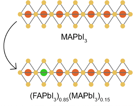
|
|||||||
| 2023 | Lab cell | T 80 | 8760 | Germany | Fine tuning of adduct formation to template crystallization and modification of solution rheology | 168 | |
|
|||||||
| 2023 | Lab cell | T 90 | 3700 | USA | Mixing of SAMs to enhance perovskite adhesion to TCO substrate and suppress electrochemical reduction of indium in ITO | 132 | |
|
|||||||
| 2024 | Submodule | T 100 | 720 | South Korea | Link of SnO2 nanoparticles with oxo groups to prevent the formation of –OH electronic defects | 91 | |
|
|||||||
| 2024 | Minimodule | T 93 | 2000 | China | Reduction of precursor solution advancing towards substrate and accelerated drying | 92 | |
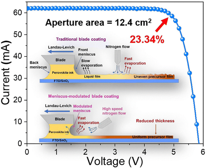
|
|||||||
| I.M. | 2017 | Lab cell | T 80 | 41 | Israel | Replacement of [60]PCBM with ETL showing lower diffusion rate of volatile perovskite decomposition product | 242 |
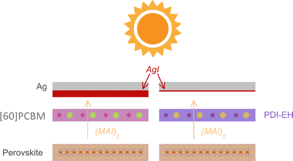
|
|||||||
| 2019 | Minimodule | T 80 | 1900 | Colombia | Perovskite morphology homogenization using mesoporous underlayer | 237 | |
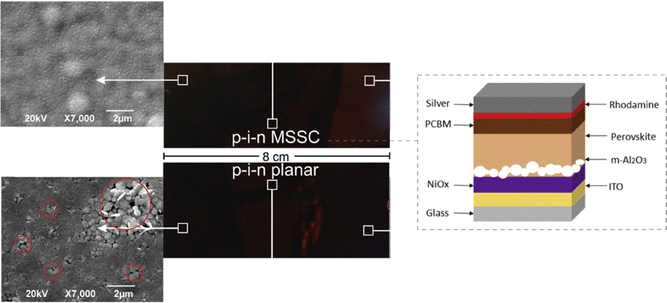
|
|||||||
| 2021 | Lab cell | T 95 | 1272 | China | Chemical bonding of migrating ions to prevent electrode corrosion and enhance electronic between perovskite and ETL | 245 | |
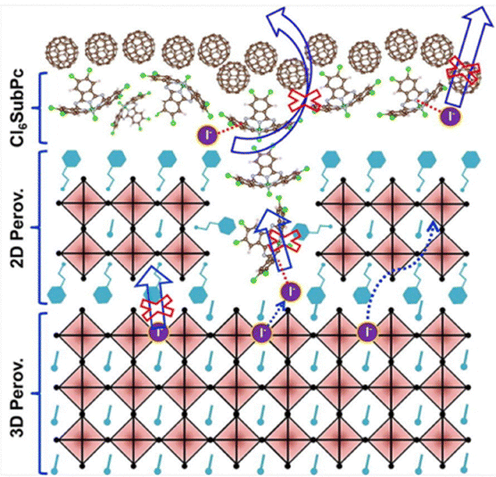
|
|||||||
| 2023 | Lab cell | T 100 | 4032 | Japan | Suppression of electrochemical lead reduction and iodine oxidation | 181 | |
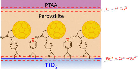
|
|||||||
| 2023 | Lab cell | T 80 | 600 | Spain | Decrease of interfacial deep and shallow traps | 235 | |
| 2024 | Minimodule | T 80 | 1104 | South Korea | Passivation of undercoordinated tin atoms in HTL via phosphate bonding | 232 | |
| 2024 | Minimodule | T 95 | 1600 | China | Suppression of lead reduction and iodine oxidation via Ni2+/Ni3+ ion pair | 248 | |
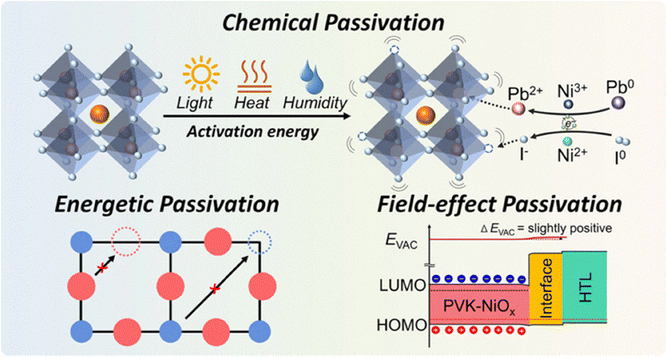
|
|||||||
| 2024 | Minimodule | T 100 | 4872 | USA | Chemical engineering of SAMs to enhance anchoring of perovskite to ITO | 93 | |
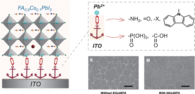
|
|||||||
| B.E.D | 2019 | Lab cell | T 80 | 450 | Israel | Fabrication of free standing back electrode with subsequent transfer onto the device | 263 |
| 2022 | Minimodule | T 80 | 1200 | Norway | Coupling of paint-brushed carbon back-electrode via graphitic carbon-MAPbI3−xClx interlayer | 262 | |
| 2024 | Minimodule | T 70 | 8400 | Poland | Use of screen-printed highly stable carbon back-electrode | 261 |
Despite this, there is a clear trend: more outdoor stability testing, with more robust devices and longer lifetimes. Fig. 4b shows how manufacturing strategies for improving outdoor stability have evolved over time. It presents representative results from different approaches, including T80, T90, T93, T95 and T100 values, tracked over several years. Among these, interface modulation has been the most studied strategy, achieving notable improvements in stability. For example, devices advanced from a T80 of just 41 hours in 2017242 to minimodules with no observable performance loss after 4872 hours of outdoor exposure.93 The bulk modification approach ranks second in terms of the number of studies, with results such as a T93 of 2000 hours in minimodules.92
Notably, while the use of carbon back electrodes has demonstrated outstanding stability potential, such as a reported T70 of 8400 hours,261 this strategy has received relatively little attention. Only three outdoor studies on carbon-based devices are included in Fig. 4b. In general, outdoor stability results in this approach trail behind those interface and bulk modifications. This issue may be attributed to the intrinsic challenges associated with exposes devices into the environment, including inadequate interfacial adhesion, suboptimal surface wettability, and insufficient ohmic contact between the carbon electrode and underlying layers.183 These issues can be further compounded in outdoor environments. Nevertheless, one of the most promising approaches to producing stable, cost-effective perovskite modules is still the use of HTL-free designs with carbon electrodes (discussed in the next subsection). There is considerable potential for large-scale deployment, particularly in situations where longevity exceeds peak efficiency. This is due to their chemical robustness, moisture resistance, and compliance with ambient, low temperature processing.
Unlike the more chemistry-oriented strategies of interface and bulk modification, the carbon back-electrode approach requires substantial engineering effort. The materials and methods for carbon electrode integration into the stack are important to achieving stable performance outdoors. The mentioned strategies can be used combined in high-efficiency devices, especially in tandem structures which require advanced techniques to improve performance.175,269–274 This is particularly relevant for tandem devices, which often require complex architectural strategies to optimize both performance and stability.275–280 While these approaches have yielded some of the highest efficiencies reported to date, they too lack systematic benchmarking under outdoor conditions. Expanding real-world validation across both single junction and tandem architectures will be essential to ensure perovskite photovoltaics meet commercial reliability standards. Some studies display devices with promising stability results under stringent conditions, such as T85 of 1250 hours,269T95 of 2000 hours,273 and T96 of 2000 hours274 under ISOSL3 protocols. Though developments seem promising, few are reported in the literature specifically showing outdoor testing.
As demonstrated in Table 1, the fabrication approaches exhibited favorable results in outdoor conditions. All studies incorporated at least one complementary indoor test, thus enabling the correlation of degradation mechanisms observed under controlled laboratory conditions with real-world operating behavior. It was demonstrated that strategies based on bulk modification (B.M.) exhibited the longest stability times, reaching T80 > 5000 h under ISOS-L1I, which an inherent improvement in perovskite stability. On the other hand, more stringent protocols (ISOS-D2, ISOS-L3) have been used to evaluate Interface Modulation (I.M.) approaches, with T90 values approaching 2000 hours and T100 values around 1100 hours. These findings highlight the efficacy of interfacial strategies even under more demanding ISOS protocols. Finally, even without encapsulation, back electrode design (B.E.D.) techniques produced T90/T100 values greater than 1200 hours, highlighting their role in mitigating degradation pathways.
In the ref. 91, which employs the bulk modification (B.M.) strategy, the ISOS-D3 protocol is used under conditions of 85 °C and 85% relative humidity. The device exhibits greater stability in indoor-D3 (T80 = 1080 h) than in outdoor tests (T80 = 720 h). This occurs because, although ISOS-D3 imposes temperature and humidity stress, this stress is constant, controlled, and static. Under such conditions, uniform diffusive and thermal processes dominate degradation, allowing both the encapsulant and the perovskite to maintain stable behavior. In contrast, the encapsulated device is subjected to a highly dynamic and multifactorial environment during outdoor tests. This environment includes real solar irradiance (including UV), day-night thermal cycles, humidity variations, atmospheric oxygen, and climatic agents like wind gusts, dew, and intermittent shading. Together, these elements speed up the encapsulant's and interfaces' deterioration and cause failure pathways that do not appear under controlled damp-heat. As a result, even though B.M. greatly increases stability indoors, its outdoor performance shows that the encapsulation used is insufficient to mitigate the entire range of degradation mechanisms, which explains the lifetime reduction from 1080 to 720 hours.
Regarding a the ref. 237 and the interface modulation (I.M.) strategy, the ISOS-D1 protocol is used with a relative humidity of 60%. Here, the absence of encapsulation is crucial in explaining the marked difference between indoor (T72 = 61 h) and outdoor (T80 = 1900 h) stability. In indoor environments without encapsulation, degradation is driven by direct exposure to ambient humidity, immediately compromising the functional interfaces. In contrast, for outdoor testing, these devices were encapsulated, preventing direct water permeation, and allowing the interfacial strategy to demonstrate its effectiveness under more complex climatic conditions. This shows that, for humidity-sensitive devices, encapsulation can become the dominant factor determining overall stability.
Finally, in the article263 evaluates the back electrode design (BED) strategy using the ISOS-D1 protocol under ambient temperature and relative humidity conditions between 25–30%. In this case, the unencapsulated device exhibits a T100 of 1440 h, while outdoors, even when encapsulated, the T80 decreases to 450 h. This demonstrates that high indoor stability does not necessarily translate to real-world conditions. Outdoors, the simultaneous presence of UV irradiance, fluctuating humidity, and thermal cycles induce degradation mechanisms, especially in the encapsulant and back contact, that remain inactive under a stable indoor environment. Consequently, indoor tests are useful for preliminary diagnosis but mandate respective outdoor validation.
To illustrate this point, we discuss representative examples in which a strategy that performs well under indoor conditions requires additional considerations to succeed outdoors, highlighting that indoor performance alone is not sufficient for real-world deployment. A prime example of this is shown by Fei et al., who demonstrate that devices using PTAA operate well and remain stable under LED-based indoor protocols but degrade rapidly outdoors.93 As the chemical mechanism behind this instability has already been described in Section 3.1.2, here we emphasize that this degradation pathway is activated primarily by UV exposure, an effect absent in conventional ISOS indoor tests. Consequently, strategies that appear robust under indoor conditions may not translate to outdoor stability unless they are specifically designed to withstand UV-induced stress. In this context, Fei et al. show that replacing PTAA with the phosphonic-acid carbazole molecule EtCz3EPA, which provides stronger anchoring at the buried interface, is necessary to preserve device performance under real sunlight. This demonstrates that although PTAA can perform well under ISOS protocols, including ISOS-LC or indoor temperatures even higher than those experienced outdoors in the study by Fei et al., while humidity-related effects are effectively suppressed through encapsulation, factors unique to outdoor environments, such as UV exposure, can activate degradation pathways not triggered indoors. This makes it necessary to adjust or replace the HTL with another material that preserves efficient hole transport while avoiding UV-induced instability. Taken together, this case shows how indoor robustness does not guarantee outdoor viability when specific spectral stressors are missing from indoor protocols.
Similarly, a widely used indoor passivation strategy involves the incorporation of PEAI to form a 3D/2D heterojunction, which effectively suppresses surface recombination under mild ISOS conditions. However, the work by Wang et al. shows that PEAI is not transferable to outdoor-like stressors because its mono-ammonium nature makes it highly susceptible to photothermal degradation.281 Under simultaneous light and heat, PEAI deprotonates and reacts with PbI2, producing Pb0 and triggering rapid iodide migration, processes that do not occur under standard indoor protocols. To overcome this limitation, the authors replace PEAI with the di-ammonium spacer BDAI2, which forms the photothermally robust Dion–Jacobson phase BDAPbI4. The strong bidentate hydrogen bonding of the di-ammonium cation stabilizes the PbI6 network, suppresses deprotonation, and prevents structural collapse under harsh ageing. This finding underscores that certain molecules performing excellently indoors may still require structural redesign to withstand full-spectrum outdoor stressors.
In the context of carbon electrodes, Lukas et al. provide another example of an indoor strategy that cannot be directly transferred outdoors.282 Although PCBM is widely used as the electron-extraction layer in indoor PIN devices, the authors show that it is incompatible with carbon pastes, since it dissolves and intermixes during contact formation. This prevents the fabrication of stable or reproducible devices, and previous work showed that only an evaporated chromium layer could protect PCBM, which increases cost and defeats the purpose of low-cost carbon contacts.283 To create a fully low-cost PIN/carbon architecture, the authors replace PCBM with ALD-SnO2. However, SnO2 alone gives limited performance and poor stability because its rigid inorganic surface forms a weak electronic interface with the carbon electrode, leading to contact resistance increases and interfacial degradation. Adding a thin PH1000 layer on top of SnO2 overcomes these limitations by improving energy alignment, charge transport, and interface quality. As a result, the SnO2/PH1000 and carbon configuration shows significantly improved stability and functionality, demonstrating a viable pathway toward low-cost PIN devices with carbon top electrodes. This illustrates a different type of indoor–outdoor mismatch rooted not in photochemistry but in interface compatibility and mechanical robustness.
Furthermore, encapsulation provides another example of a strategy that performs well under indoor ISOS tests but fails outdoors. Emery et al. show that UV-glue “LAB” encapsulation, commonly used in perovskite research, preserves more than 93% of the initial efficiency for over 1500 h under ISOS-D1 storage, giving the impression of strong protection.284 However, under damp-heat conditions (85 °C/85% RH) or real outdoor exposure, LAB-encapsulated devices degrade rapidly, often failing within days. This poor transferability arises from the inherent limitations of UV-cured epoxies, including micro-cracking, high WVTR, and interfacial damage introduced during curing. Outdoors, these weaknesses permit moisture ingress and edge-initiated decomposition, effects not revealed by indoor tests. To address this issue, the authors implemented a commercial lamination stack consisting of a polyolefin encapsulant and a butyl rubber edge seal. This provides low permeation rates and higher mechanical stability. Devices encapsulated using this method pass IEC 61215 damp-heat testing and retain almost full efficiency after spending more than ten months outdoors. This demonstrates that, like interfaces and contact layers, encapsulation must be validated directly under outdoor conditions to ensure real-world durability.
Collectively, these examples show different strategies for improving device stability and highlight the gap between good development in indoor tests and outdoor tests, spanning from interface modifications to back electrode design and encapsulation. This message makes clear that the strategies at the edge of the state of the art tested only indoors should be tested outdoors to analyze their transferability and ensure adequate development or the needed optimizations. Therefore, we propose testing some recent strategies in outdoor conditions that work very well indoors and could have promising behavior outdoors. Two high-efficiency interface modulation strategies recently reported under indoor ISOS testing highlight the need for outdoor validation. Liu et al. introduce a bimolecular treatment combining PDAI2, which induces a field-effect at the perovskite/C60 interface to block holes, with 3MTPAI, which passivates iodide vacancies through S–Pb interactions;274 this synergistic design suppresses interfacial recombination and enables certified PCEs above 25% with >1500 h indoor stability (>T90). Chen et al. develop dual-site aromatic sulfonate ligands such as 4Cl-BZS that bind two adjacent Pb2+ sites and improve the energetic and mechanical coupling with C60, producing >26% certified efficiencies and strong stability under ISOS-L3 protocols during 1200 h (T95).272 Both treatments rely on ultrathin molecular layers that are solution-processable and compatible with scalable coating, but neither was evaluated under sunlight containing UV, humidity variations, or thermal cycling. Their excellent indoor performance therefore makes them compelling candidates for outdoor testing to assess the robustness and transferability of these interface-engineering concepts under real-world conditions.
In addition to interface engineering, several recent indoor-only stability advances based on molecular and polymer additives for bulk modification highlight promising yet unvalidated pathways for real-world operation. Sun et al. introduce a stepwise melting-polymerizing molecule (SMPM) that melts, infiltrates grain boundaries, and polymerizes in situ, forming a hydrophobic grain-scale encapsulation that strongly suppresses humidity-driven degradation (T95 at 2000 h at 85% RH) and stabilizes FAPbI3 through hydrogen bonding and Pb2+ coordination.285 Simultaneously, Shi et al. develop mechanically interlocked networks (MINs) that regulate colloidal particle distribution during printing, yielding highly uniform large-area films with enhanced crystallinity and mechanical robustness, an approach fundamentally compatible with scalable coating methods such as blade or slot-die processing (>T90 after 1000 h at 65 °C).286 Finally, Xiong et al. propose an additive strategy using alkali metal oxalates to homogenize Cl distribution, suppress surface aggregation, and improve interfacial coupling, enabling >27% indoor PCE and strong thermally driven MPPT stability (>T80 after 1000 h at 85 °C).287 None of these three approaches have been tested in outdoor conditions with fluctuations in humidity, temperature, or light with UV components. However, all are based on ultra-thin molecular layers or solution-processable additives that are in principle compatible with large-scale manufacturing techniques. These strategies are therefore excellent candidates for systematic outdoor validation to determine their actual transferability to real-world conditions due to their outstanding indoor performance.
Ultimately, these examples show that potentially viable strategies for outdoor performance have not yet been evaluated under real operating conditions, and they corroborate whether they are truly viable or if some adjustment or optimization of the molecule or strategy is necessary. These are directly applicable improvements for devices exposed to actual outdoor conditions, and they could accelerate the stability of solar cell devices and bring their commercialization closer.
HTLs used in n–i–p devices (such as Spiro-OMeTAD and PTAA) show thermal and photo-induced degradation in the operational range (≈70–85 °C).288 In doped Spiro-OMeTAD, device performance drops rapidly at ≈85 °C while other layers remain comparatively stable; part of this decay is irreversible due to dopant loss. In particular, tBP evaporates at ≈85 °C, causing voids, pinhole formation, and morphological failure,289,290 effects that can be partially mitigated by the top metal electrode.288,291 Also, under humid conditions, the hygroscopic Li-TFSI dopant accelerates underlying perovskite degradation; higher Li-TFSI content correlates with faster moisture-driven decay, and at high RH Spiro-OMeTAD or PTAA films crack and fragment on the perovskite, enabling water and ion ingress.119,288,292 Meanwhile, Au electrode migration through Spiro-OMeTAD occurs under illumination even at 70 °C, causing shunts and trap formation.288,293 For PTAA, doping with Li-TFSI + tBP increases conductivity but also introduces light-assisted oxidation features (e.g., a new absorption band at 440–550 nm assigned to PTAA+ under illumination), while shifting the energy levels and affecting morphology; optimized films still benefit from thin, pinhole-free coverage to minimize transport losses.294 A remarkable exception of this degradation pathways is the work by Babu et al., who reported a PTAA based carbon electrode perovskite module with operational stability lasting one year.261 Maybe, this result was made possible using a highly durable encapsulant that mitigated moisture and HTL degradation effects. Nevertheless, the requirement for multilayer encapsulation and the high cost of the HTL material also resulted in extra expenses.
Although the device is protected from moisture and light by carbon electrodes, organic HTLs still degrade significantly, and the most stable carbon based devices reported in the literature are typically HTL-free. This is due to the intrinsic stability issues associated with organic HTLs. Passatorntaschakorn et al. fabricated HTL free, carbon-electrode PSCs that achieved a maximum PCE of 11.09% and retained 73% of their initial efficiency after about 20232 h under ambient ISOS-D1 (∼25 °C, 35–45% RH).295 In comparison, Spiro-OMeTAD based-devices with 13.95% of initial PCE retained only 40% PCE over the same period in the same test.
To overcome the hole extraction barrier associated with HTL free devices, Lin et al. developed a 1D/3D heterojunction by incorporating thiocholine iodide derived TchPbI3 at the surface of CsPbI3.296 Their optimized devices achieved a certified PCE of 18.7% and retained over 90% of their initial efficiency after 300 hours of continuous maximum power point tracking (1 sun exposure) under inert conditions. This strategy also shows potential for outdoor deployment. Selvakumar Pitchaiya et al. demonstrated that HTLfree, carbon electrode PSCs retained more than 80% of their initial PCE after 50 days (approximately 1200 hours) of outdoor exposure.297 Likewise, Siram et al. reported that fully inorganic CsPbBr3 unencapsulated devices using a carbon nanotubes (CNT)/perylene diimide (PDI) back contact, without any HTL, lost less than 30% of their initial performance after approximately 6 weeks of outdoor testing in desert weather conditions.263
Despite their excellent stability, HTL free devices usually have lower efficiency because of less hole extraction. Alternatively, inorganic HTLs like CuSCN and NiOx can be used. Unlike Spiro-OMeTAD and PTAA, which degrade at about 85 °C, these materials can withstand thermal and photo-oxidative degradation up to 100 °C.298–301 Long-term stability is enhanced by their nonhygroscopic nature, which inhibits ion migration and moisture-induced film swelling.263,302,303 Zhang et al. carried out a large-scale study, which included over 7000 PSCs, demonstrating that simply swapping out organic HTLs for carbon electrodes increased normalized device lifetime by 4.2 times.105 Stability was increased around 7.2 times by adding an inorganic HTL below the carbon contact. When compared to organic HTLs, inorganic HTLs alone (without carbon electrode) provided a 1.8-fold increase in TS80m values, indicating that they may be able to strike a balance between stability and hole extraction. Wu et al. demonstrated that a CuSCN and carbon nanotube bilayer improved the open-circuit-voltage from 0.85 V to 1.01 V and fill factor from 0.60 to 0.73, resulting in a champion PCE of 17.58%. These devices maintained approximately 80% of their initial performance after 1000 hours of continuous one-sun illumination under an inert atmosphere.304
Unlike organic HTLs, inorganic HTLs such as NiOx and CuSCN usually offer higher stability but often suffer from incomplete coverage, high surface roughness or low hole mobility, even with careful synthesis and interface engineering.305–307 These morphological defects are conducive to interfacial recombination, reducing the PCE compared to organic HTLs, which spontaneously form a thin, smooth, high-hole mobility film. For instance, mesoporous or nanoparticle-based NiOx films require optimization,308 particularly in terms of thickness, doping, and nanoparticle dispersion, to minimize voids and achieve the improved efficiencies reported for electrochemically deposited NiOx and dopant or additives modified NiOx.309,310 Likewise, CuSCN-based devices typically achieve efficiencies of ∼15–16% PCE but with interface passivation (i.e., (3-Mercaptopropyl)trimethoxysilane (MPTMS)), improved efficiencies can surpass 20%.311,312 Thus, while inorganic HTLs can be more stable, the quality of the organic HTLs in as-fabricated films is better, unless further engineering on the inorganic HTLs is undertaken.
Despite the mentioned advances in HTLs, eliminating the HTL layer offers several advantages. It enables ambient, low-temperature processing, removes the need for controlled-atmosphere HTL deposition and dopant incorporation, and avoids high-temperature annealing steps. Passatorntaschakorn et al. reported that this simplification improved reproducibility and reduced module material costs by approximately 97% compared to HTL based workflows.295 Carbon paste electrodes cost only $0.01 per gram, about 1.4% the price of silver, leading to a 69.7% reduction in perovskite module material costs compared to noble metal based devices.313 Projections from techno-economic modeling indicate that HTL-free, carbon electrode PSCs could achieve manufacturing costs as low as $22.70 per m2 in large-scale production, highlighting their potential for cost effective, high throughput commercial production.314
3.2. Influence of device architecture on stability
The mainstream device architecture used in the field of perovskite solar cells are n–i–p and p–i–n, which differ in the order of stacking the layers: in the former, sunlight first goes through the ETL before reaching the perovskite absorber while in the latter it first goes through the HTL. In the n–i–p architecture, instability issues related to the use of Spiro-OMeTAD have been frequently mentioned, although big-data driven investigation have shown that in general, and not being limited to outdoor stability results, n–i–p devices have shown slightly higher overall stability.105 In this sense, it is interesting to compare these tendencies exclusively in the outdoor stability landscape. Additionally, the mesoscopic carbon architecture is considered, due to its considerably different approach to fabrication: the transport layers and/or the carbon back electrode are deposited first followed by an infiltration of the perovskite absorber. This architecture is particularly remarkable since the earliest results of relatively high outdoor stability were attained following this configuration.44,266Fig. 4c shows a box plot comparing the outdoor stability results of the mentioned architectures across all the papers reviewed in this work which explicitly showed outdoor evaluation, in which the insets correspond to the average stability time. It is important to note that more papers were considered here than the ones previously shown in this section, since the discussion was limited to works in which the fabrication strategy was the focus for a richer overview of such strategies. The distinction between T70–T85 and T90 or higher is made to facilitate the comparison between the results, as the reported values were not standardized to a benchmark parameter. A total of 50 reports were considered, of which 27 (54%), 18 (36%) and 5 (10%) employ the n–i–p, p–i–n and mesoscopic carbon architectures, respectively. From those works using the n–i–p architecture, 20 (74.07%) reported a T70–T85 while 7 (25.93%) reported a T90 or higher. For the p–i–n and mesoscopic carbon architectures these numbers correspond to 11 (61.11%) and 7 (38.89%), and 2 (40%) and 3 (60%), respectively. In agreement with the general tendencies in perovskite photovoltaic research, most outdoor stability results correspond to n–i–p devices, followed by p–i–n and mesoscopic carbon. Except for the mesoscopic carbon architecture, in most works an outdoor stability corresponding to T70–T85 has been reported, although in recent years improvements in stability have led to a higher ratio of reports of T90 or higher, e.g., in Fig. 4b most of the reported stability times in 2023 and 2025 are T90 or higher. In terms of T70–T85, a higher average of 7972.5 h has been achieved in p–i–n devices, followed by n–i–p (1106.1 h) and mesoscopic carbon (875 h). In the case of T90 or higher, the highest average of 2553. 14 h was achieved with n–i–p architecture, followed by p–i–n (2041.71 h) and mesoscopic carbon (998 h). Nonetheless, the discrepancy in number of reports and time of evaluation makes the comparison of averages elusive and instead looking at the best result from each architecture shines light onto their viability for stable real-world operation. In terms of T70–T85, comparable outdoor stability times of 8400 h261 and 35040 h46 have been achieved in n–i–p and p–i–n architectures, respectively, while mesoscopic carbon lags with a maximum value of 1200 h. As for T90 or higher, the p–i–n architectures comes on top with a maximum outdoor stability time of 4870 h,93 followed by n–i–p with 4032 h181 and mesoscopic carbon with 2250 h.264 In general, this hints to higher attained outdoor stability for the p–i–n architecture, although in general this shows a promising landscape of durable devices regardless of architecture.
Fig. 4d shows an overview of the retained PCE as a function of the stability time of all the reviewed reports that explicitly showed outdoor evaluation, in which the bulk of results are concentrated in times below 4000 h and those displaying the longest time for each architecture (highlighted as a star) follow the same trend as the T90 or higher discussed above: p–i–n > n–i–p > mesoscopic carbon. Furthermore, for both n–i–p and p–i–n architectures, the longest outdoor stability periods without any performance loss were achieved in 2023 and 2024, further corroborating the recent trend. Interestingly, only 10 of the reports considered here (shown as hollow data points in Fig. 4d) are found as entries in the Perovskite Database, pointing to a lack of willingness in the community to update this valuable resource. Having centralized access to up-to-date outdoor stability data is key to keeping track of progress in the field and possibly facilitate collaboration between different research groups in the world, and thus it is highly encouraged for following investigations to update the database.
4. Additional strategies for stable device operation under real world operating conditions
When discussing the stable operation of both, PSCs and perovskite solar modules (PSMs) under real-world conditions, it refers to maintaining the device's stability while operating under illumination, with a working load/bias, and within the specific environmental conditions of its deployment.60 As highlighted in previous sections, various strategies exist to enhance the intrinsic stability of PSCs. However, other processes are essential to further improve device performance and durability. Both small-scale lab cells and large-area PSMs are vulnerable to harsh outdoor conditions without proper encapsulation, a critical requirement for any commercial technology.94,315,316 Moreover, several strategies can be employed to optimize device operation, as indicated in Fig. 5, and discussed below. | ||
| Fig. 5 Schematic process line illustrating other strategies to enhance the long-term stability and performance of PSCs under real-world operating conditions. These strategies include: (1) optimized device interconnection designs, such as parallel or series configurations enabled by P1–P2–P3 laser patterning and contacts (e.g., Silver); (2) functional surface modifications, including self-cleaning and antireflective coatings composed of materials (e.g., MgF2, SnO2, Al2O3, or PDMS) that also improve light harvesting; and (3) encapsulation using barrier materials (e.g., PIB, EVA, PDMS, POE, TPU, or epoxy resins) to protect the device from moisture (H2O) and oxygen (O2) access. | ||
4.1. Device interconnection and design
The first strategy includes device interconnection and design, which is crucial for controlling current and voltage output of large-area devices,315,317 which can be done by modulating series and parallel connection modes. Gao et al.318 demonstrated that, for four PSCs with an active area of 6.12 cm2, the most effective way to maximize output power in PSM was to first connect two pairs of cells in series and then interconnecting them in parallel. This type of design is especially relevant for scaling up, as electrical interconnection becomes mandatory in large-area modules. In this context, the PSM interconnection design is based on three steps known as P1, P2 and P3, which are essential to ensure efficient and stable operation; these steps are typically carried out by laser ablation.319,320 P1 consists of the removal of the transparent conducting oxide (TCO), such as indium tin oxide (ITO) or fluorine-doped tin oxide (FTO), directly on the substrate, in order to electrically isolate the subcells and avoid lateral short circuits. P2 is the most critical process, as it allows the electrical series connection between subcells by carefully removing the top layers such as HTL, PVKT and ETL without damaging the TCO, that is, this connection allows current to flow from the back contact of one cell to the TCO of the next, achieving a series interconnection that sums the voltage of each subcell. By removing the top layers of the stack, the TCO is exposed, allowing the back contact of the adjacent cell to be deposited directly on it, forming an ohmic connection that ensures efficient charge transfer. However, poor execution of P2 can cause damage to the TCO or incomplete contacts, increasing the series resistance or inducing the appearance of short circuits. Finally, P3 is responsible for isolating the subcells present in the device.319–322Now, under real-world operating conditions, one of the main limitations faced by PSMs is the phenomenon of reverse bias.323 This occurs when one or more series-connected cells are partially or fully shaded, generating an inverse voltage that intensifies ionic migration processes. That is, when a configuration is in series, all cells share the same current and when one of them is shaded, the others force the current through it, generating a reverse potential. This charge redistribution generates an electric field that favors the movement of mobile ions such as I−, MA+, or FA+ from the bulk to the interfaces, promoting undesirable reactions, vacancy formation, tunneling phenomena, and delamination, ultimately leading to partial or irreversible degradation of the device.324 With a short polarization duration, reverse polarization degradation is partially recoverable through the redistribution of migrated ions. When polarization is prolonged or repeated, the degradation gradually becomes irreversible, involving I− oxidation by injected holes.52 In summary, the combination of localized charges, reverse voltages, and accelerated ionic transport in series/parallel configurations under realistic conditions can trigger chemical degradation processes both at the interfaces and in the active volume of the cell.162 This phenomenon is frequently observed in series-connected configurations, especially in outdoor-tested minimodules, where variable environmental conditions such as shading, dust, or intrinsic defects cause cells to operate asynchronously, resulting in hot-spot formation, localized overheating, and energy loss.237,325–328 A representative example of this configuration has been reported in large area perovskite solar panels (PSPs) with an area of 0.5 m2, composed of minimodules with 10 series-connected cells, arranged in 5 parallel strings, each consisting of 8 modules in series, totaling 40 PSMs per panel.325
To address these challenges, various mitigation strategies have been proposed, such as the use of ion-blocking layers like doped NiOx, Al2O3, or self-assembled monolayers (SAMs), which limit ionic movement toward sensitive interfaces,329–332 reducing mobile ionic defects through compositional engineering; and incorporating bypass diodes to protect shaded cells. However, the implementation of bypass diodes can increase system costs, particularly in PSCs, which have lower breakdown voltages compared to conventional photovoltaic technologies. In this context, carbon-based PSMs have shown promise as a robust solution. Recent studies report that these modules can withstand reverse voltages of up to −9 V, passing the hot-spot test defined by the IEC 61215-2: 2016 standard without efficiency loss, highlighting their potential for industrialization and suitability for large-scale applications.333Table 2 below summarizes the main structural and design strategies employed to mitigate ionic migration induced by reverse bias.
| Configuration/modification | Blocking material | Evaluated conditions | Results | Ref. (DOI) |
|---|---|---|---|---|
| PSCs with series interconnection and bypass diode | Bypass diode + carbon | −9 V, 1 week (IEC 61215–2) | Without loss of efficiency | 333 |
| PSCs with doped NiOx layer | NiOx (e.g. Cu:NiOx, Ag:NiOx) | Reverse bias, thermal stress | Reduction of ionic accumulation, enhanced thermal stability | 331 |
| PSCs with SAM on SnO2 | Self-assembled monolayer | Leakage current and J–V measurement | Partial suppression of ion migration | 334 |
| PSCs with ultrathin Al2O3 ALD | Al2O3 | Thermal + electrical stress (MPPT, 85 °C, 85% | Hindered I− and MA+ migration, improved interfacial stability | 332 |
| PSCs with secure interconnection and appropriate encapsulation | Encapsulated + POE + PIB | Outdoor test, simulated partial shade | Sustained stability for 10 months | 284 |
4.2. Protective and functional layers
To maximize power generation, it is important both to maintain stable performance and to have the maximum PCE possible. As previously discussed, it can be achieved by different strategies for the cell stack, but it can also be done after the PSM is fabricated. Specifically, it is possible to incorporate protective and functional layers such as anti-reflective,335–338 self-cleaning338,339 and UV-absorbing coatings.340,341 For instance, super-hydrophilic antireflection (AR) films coated on photovoltaic glass have been demonstrated to significantly improve solar transmittance across broadband wavelengths (380–1100 nm), thereby boosting efficiency.342 However, while AR films enhance optical performance,335,337 they do not inherently improve device stability.341,343–345 Currently, anti-reflective films have been applied to 90% of commercial solar panels.346,347 Commonly used materials to fabricate antireflection films include magnesium fluoride (MgF2),348,349 zinc oxide (ZnO),350,351 silicon oxide (SiO2),352–355 titanium oxide (TiO2),356,357 aluminum oxide (Al2O3)358 and polydimethylsiloxane (PDMS),337etc. Among these, the most widely used is SiO2, due to its low price and good chemical stability. It is often used for the preparation of anti-reflection films by a simple and controllable sol–gel method. In this same context, to further improve optical efficiency, researchers have explored the use of nanostructures, such as nanocones338,359 made from the materials like MgF2, ZnO, SiO2, TiO2, Al2O3 or PDMS, which represent a promising solution for reducing reflection losses. These structures allow the generation of a refractive index (RI) gradient at the air-solid interface, effectively reducing surface reflection.359,360Looking ahead, future challenges of these protective and functional layers will involve optimizing integration during labscale production, while ensuring cost-effectiveness. The development of new materials or hybrid coatings with multifunctional properties, such as combining anti-reflective, self-cleaning, and UV-absorbing capabilities, could provide more holistic solutions. Overcoming these challenges will be crucial for the continued advancement of PSM and its successful integration into large-scale renewable energy systems.
4.3. Encapsulation
Encapsulation is essential for protecting PSCs from environmental stressors such as moisture, oxygen, and UV radiation. Materials used for encapsulation must meet several criteria: chemical inertness, high light transmittance (>90%), low water vapor transmission rate (WVTR) between 10−3 and 10−6 gm−2 day, low oxygen transmission rate (OTR) between 10−3 and 10−5 g m−2 day, high electrical resistivity, and mechanical durability.31,95,172,284,361,362 In addition, functional carbon electrodes or carbon-based layers can serve not only as conductive elements but also as protective barriers or encapsulants, resisting moisture and oxygen ingress and thus enhancing device stability.363–365 These carbon layers can reduce the influence of the external factors and degradation pathways, further supporting the long-term operation of perovskite solar cells in real-world conditions. On the other hand, traditional encapsulants like ethylene vinyl acetate (EVA) for glass-to-glass encapsulation, commonly used in silicon solar cells, require lamination temperatures around 150 °C and are prone to optical degradation, delamination and acetic acid formation, making them unsuitable for PSCs.94,361,366 Therefore, alternatives to EVA exist, such as ionomers,42,367 polyurethane264 or polyolefins (POE).94,264 Even though EVA has been used for encapsulation of PSM and panels,29,368 the reduction of the processing temperature to values around 85 °C does not allow proper cross linking, leading to premature moisture and oxygen interaction with the devices.325 Also, for rigid devices, glass-to-glass encapsulation with UV-curable polymers has proven effective. Specifically epoxies, widely used in the industry, exhibit good moisture resistance and studies have demonstrated the stability of UV-epoxy-cured devices in the range of 500 to 2000 h of outdoor exposure.237,369 However, it has been determined that the exothermic curing process of UV-curable epoxy resins can damage cells due to their mechanical rigidity and thermal stress,361 they are also prone to aging and yellowing370 and they may be also susceptible to delamination at elevated temperatures.33 To mitigate these effects, polyvinylpyrrolidone (PVP) interlayers have been implemented.315 For the case of flexible devices, using polymeric substrates such as polyethylene terephthalate (PET), polyethylene naphthalate (PEN) and polyimide (PI), the encapsulation materials require high ductility and compatibility with roll-to-roll fabrication processes. Thermal load during encapsulation must also be carefully managed to avoid damaging organic substrates.361 Promising alternatives include solution-based poly(methyl methacrylate)/styrene-butadiene (PMMA/SB) bilayer structures, which are cost-effective and scalable for both rigid and flexible devices.26Other materials, such as thermally evaporated MgF2 or MoO3−x capping layers, combined with glass and UV-curable polymers, have shown excellent encapsulation performance.371 Recent advancements in encapsulation materials include the use of thermoplastic polyurethanes (TPUs), which stand out for their high thermal stability, scalability, and flexibility.372 In addition, TPUs have good chemical inertia against environmental agents such as moisture, oxygen and UV radiation, preventing the degradation of perovskites to PbI2 and thus improving device stability.370 For example, polyether based TPUs are preferred for moisture exposure applications, since they offer greater hydrolysis resistance. However, at high temperatures, these materials may suffer oxidation, which causes yellowing and loss of mechanical properties. Similarly, prolonged exposure to UV radiation degrades the material and hinders encapsulation.370 TPUs are formed by cross-linking polyether polyols (e.g., polypropylene glycol (PPG) and polyethylene glycol (PEG)) with isocyanates (e.g., isophorone diisocyanate (IPDI) and toluene diisocyanate (TDI)). These materials are highly tunable, making them suitable for diverse applications, including PSCs encapsulation.373 Butyl rubber-based polymers, such as polyisobutylene (PIB) has been validated as an effective material for both primary encapsulation and edge sealing because of its efficient moisture barrier properties33 achieved by its low water permeability and stability in accelerated aging tests.33 In this context, edge sealants play a crucial role in preventing delamination and cracking at the encapsulant edges, ensuring the long-term structural integrity of the device. The use of PIB as edge sealant with desiccant materials to prevent moisture and oxygen ingress, combined with polyolefins (POE) films for mechanical stability has demonstrated to be a good strategy, inspired by commercial CIGS module encapsulation, as it has demonstrated excellent outdoor stability (ISOS-O3) when compared to typical encapsulation using UV curable epoxies, as they were able remaining stable for over 10 months.284 This effectiveness is largely due to the careful selection of materials, where the selection of the edge sealant is due to its low water vapor transmission rate (WVTR) and low glass transition temperature (Tg),94 making it compatible with mechanical stresses induced by extreme weather conditions.374 Additionally, POE films have excellent adhesion, water resistance and Young's modulus of 8 MPa (mechanical property that measures the stiffness of a material, that is, its ability to resist elastic deformation under an applied load), contributing to mechanical stability.42 However, their application requires temperatures above 80 °C, which could compromise the structural integrity of the device.315 Furthermore, POE's high volumetric resistivity (≥1017 Ω cm at 23 °C) minimizes the risk of potential-induced degradation, thus prolonging the device lifetime.361 In general, materials such as polyisobutylene (PIB) and polyolefins (POE) not only offer a high barrier to the permeation of water and oxygen vapor, but also have chemical inertia, which allows them to avoid reactions with volatile species such as HI or MAI, which can be released from bulk in conditions of thermal stress. This inertia makes them excellent candidates for sealing edges and encapsulant. In addition, their high volumetric resistivity and low vitreous transition temperature allows them to mechanically adapt to real environmental conditions without compromising structural integrity.
Other materials have been extensively studied and employed in the encapsulation of PSCs, standing out for their effectiveness as moisture barriers, compatibility with devices, and ease of processing. Among them, polydimethylsiloxane (PDMS) has demonstrated high hydrophobicity and flexibility, contributing to extending PSCs stability up to 3000 hours.315 In general terms, hydrophobic materials such as PDMS and TPU are advantageous in applications where environmental exposure to moisture is critical. Its repellent water surfaces limit the adsorption and dissemination of H2O, which reduces the probability of decomposition reactions driven by hydrolysis. These properties, combined with their mechanical adaptability, make them suitable candidates for flexible substrates in outdoor environments. For applications requiring superior thermal and chemical stability, silicones and glass frits have been used as alternative encapsulation solutions.316 Overall, the combination of encapsulants such as POE or PU with edge sealants like PIB or epoxies has proven to be an effective strategy to enhance the durability and reliability of PSCs, providing increased protection against environmental factors and ensuring long-term stability.33 In fact, recent studies have reported operating times exceeding one year under real-world conditions, using POE as the encapsulant and PIB as the edge sealant, confirming the technical feasibility of this combination for long-lasting photovoltaic applications.375
The encapsulation process itself is critical to ensure their stability and durability under real operating conditions, as can be done with and without vacuum assistance. It is commonly carried out in a vacuum laminator, which removes the air and prevents the formation of air bubbles inside the device. This approach is compatible with industrial processes and allows for homogeneous fusion and curing of both the barrier films, i.e. POE, PIB and ionomers,94,284,376 ensuring uniform and effective protection barrier against moisture and oxygen.377 As POE films are polymers that require a high-temperature cross-linking process, depending on the vacuum used, they can be incompatible with the thermal sensitivity of MAPI-based PSCs. In contrast, ionomers can be processed at lower temperatures, as their cross-links are formed through ionic interactions.378 However, these ionomers present additional challenges, such as poor adhesion to glass surfaces. To reduce water permeability and improve adhesion in the encapsulation, the use of the previously mentioned edge sealants based on PIB filled with edge desiccant is recommended,121 which offer a low water vapor transmission rate (WVTR) and a low glass transition temperature.374 PIB can be processed at a lower temperature than ionomers or POE. However, it has been observed that configurations combining POE with edge sealants can suffer from delamination under thermal cycling, highlighting the importance of optimizing processing conditions.377 In conclusion, the selection of the encapsulant should consider a combination of moisture and oxygen barrier, mechanical strength, and thermal compatibility, avoiding processing temperatures that may compromise the integrity of the perovskite material and is still under continuous investigations. To provide a clearer comparison of the encapsulation strategies discussed, Table 3 summarizes key materials used for both edge sealing and primary encapsulation in perovskite solar cells. It highlights their main advantages, limitations, type of solar cell substrates tested, and suitability for real-world operating conditions.
| Material | Compatibility with perovskite | PSCs tested under real conditions | Advantages | Limitations | Type of substrate | Ref. |
|---|---|---|---|---|---|---|
| a Partial: These materials have been implemented or evaluated under real-life operating conditions; however, they have limitations in terms of adhesion, chemical stability, and resistance to moisture and oxygen. Therefore, they require improvements to be implemented under outdoor operating conditions. | ||||||
| Ethylene Vinyl Acetate (EVA) | No | No | Economical and widely used for traditional technology | Prone to optical degradation, delamination, and acetic acid formation. Requires high temperature lamination that degrades the perovskite | Rigid | 94 and 361 |
| Thermoplastic Polyurethane (TPU) | Yes | Yes | High thermal stability, lightweight, processable | Still in large-scale validation | Rigid and flexible | 264, 370 and 373 |
| Polyolefins (POE) | Yes | Yes | Good adhesion, high resistivity, flexible | Curing temperatures >80 °C | Rigid and flexible | 94, 264 and 373 |
| Polyisobutylene (PIB) | Yes | Yes | Low WVTR, good adhesion, flexible | May delaminate under thermal cycling if not optimized | Rigid and flexible | 33 and 370 |
| Ionomers | No | Partiala | Processable at low temperatures, moderate performance | Poor adhesion to glass | Flexible | 42 and 367 |
| Epoxy resins UV curable | No | Partiala | Good resistance to humidity | Susceptible to damage from exothermic curing (thermal stress and stiffening), release of volatile compounds and delamination at high temperatures | Rigid | 26, 370 and 380 |
| Bilayer (PMMA/SB) | Yes | Yes | High stability under real-world conditions, corrosion and water resistance, good adhesion to substrates, and can be applied via a simple and cost-effective solution-based process, without the need for complex techniques such as ALD or UV/thermal curing | It requires considerable thickness (>10 µm), which can affect flexibility; in addition, the solvent in the SB layer can damage the Transport Layers | Rigid and flexible | 26 |
| Combined (PIB + POE) | Yes | Yes | High barrier against moisture and oxygen, excellent adhesion, good mechanical stability, high electrical resistivity, and outstanding durability under real-world operating conditions | Use of processing temperatures above 80 °C for POE may compromise the integrity of some perovskites and has a risk of delamination during prolonged thermal cycling | Rigid and possibility flexible | 372 |
| Multilayer (Polyvinyl chloride belt/silicone/barrier foil/UV adhesive/perovskite carbon module/UV adhesive/barrier foil/double sided tape/polycarbonate sheet) | Yes | Yes | Flexibility for curved surfaces and provides mechanical robustness against harsh environmental conditions | Initial efficiency drops due to repeated bending and susceptible to surface soiling | Flexible | 261 |
In conclusion, encapsulation remains one of the most critical steps to achieve long-term stability of PSCs outdoors. Among the strategies evaluated, the combination of polyolefins (POE) as the primary encapsulant and polyisobutylene (PIB) as the edge sealant has proven to be one of the most efficient solutions. This is attributed to its excellent moisture barrier properties, mechanical flexibility, and chemical stability, which together help mitigate environmental degradation mechanisms such as delamination, oxygen ingress, and moisture diffusion. However, challenges such as high processing temperatures (in the case of POE) and poor adhesion of certain ionomers to glass remain obstacles to its large-scale implementation. Future efforts should focus on improving material compatibility, reducing curing temperatures, and developing industrial-scale encapsulation techniques (e.g., vacuum lamination) that preserve device integrity.
Due to the absence of standardized test conditions, comparing the performance of the various encapsulation materials reported in literature remains a challenge. To address this, it is essential to establish unified evaluation protocols that reflect real-world (outdoor) operating environments and consider key variables such as device configuration, climate exposure, and mechanical stress. Advancing in this direction will not only enable more meaningful comparisons but also accelerate the development of durable and commercially viable PSCs. In this context, the Photovoltaic Accelerator for Commercializing Technologies (PACT) at Sandia National Laboratories379 plays a pivotal role by conducting outdoor field testing, validating performance metrics, and promoting the creation of test standards aimed at accurately assessing field behavior and predicting long-term degradation. In the following section, we review the main advances in characterization of PSCs under real-world operating conditions.
5. Comprehensive characterization of PSCs under real-world operating conditions
5.1. Standard protocols and key parameters for outdoor testing
Device performance can be evaluated in a controlled laboratory (indoor) or under natural sunlight (outdoors) conditions, allowing for direct comparisons of device behavior under specific conditions like Standard Test Conditions (STC, irradiance of 1000 W m−2 and cell temperature of 25 °C). However, to better assess the impact of real-world environmental factors on performance, additional power rating conditions (PRCs) are recommended (IEC 61215-1-1, 2016; IEC 61215-2, 2016; IEC 61853-1, 2011). These include Nominal Operating Cell Temperature (NOCT: 800 W m−2, 20 °C ambient temperature), Low-Irradiance Condition (LIC: 200 W m−2, 25 °C cell temperature), High-Temperature Condition (HTC: 1000 W m−2, 75 °C cell temperature), and Low-Temperature Condition (LTC: 500 W m−2, 15 °C cell temperature). Additionally, thermal performance tests are conducted beyond electrical measurements to comprehensively characterize photovoltaic devices, including solar cells, sub-assembly of cells, and PV modules. Therefore, the instrumentation, infrastructure, test duration, and estimation procedures may vary significantly between indoor and outdoor testing settings.For indoor testing, the primary light source is the solar simulator, allowing control over the irradiance level. In contrast, the device's temperature can be externally controlled to reach the target temperature. As a result, a complete characterization is carried out, including performance and temperature coefficients.381 On the other hand, achieving performance reproducibility in natural sunlight is challenging. First, there is no control over the irradiance level; it varies depending on the presence of clouds, haze, smoke, and seasonal changes. Second, keeping consistent operating conditions as PRCs to ensure similar temperature and irradiance levels during exposure is difficult. Third, depending on the location, different operating conditions may arise throughout the year due to seasonal variations.382 Thus, the PRCs cannot be measured during exposure or may not be the most representative conditions concerning location. This leads to uncertainty in the exposure duration because there is no solid knowledge about the time necessary to measure data that is considered statistically reliable. Moreover, additional uncertainty could be derived from additional elements used for outdoor testing such as tracker mechanisms, the equipment used to measure the performance (accuracy, sampling time, etc.), and data processing to estimate performance.383,384 Therefore, the instrumentation, equipment, and data processing for outdoor tests may differ from those used indoors to ensure reproducible tests.
To fully characterize PV devices, it is necessary to evaluate the impact of temperature variations throughout the months (seasonal behavior) on their performance. The effect of temperature on PV devices is mainly considered through the thermal coefficients (TCs) for maximum power (Pmax), open circuit voltage (Voc), and short circuit current (Isc). These are typically estimated as the slope of the linear regression of the processed I–V curve data as a function of device temperature ranging between 25 and 65 Celsius degrees (°C). TCs could be sensitive to solar simulator spectral distribution depending on PV technology (temperature-dependent spectral mismatch), requiring a spectral correction. In contrast, under natural sunlight, spectral correction is unnecessary385 (IEC 60891 Ed. 3.0 b:2021, 2021). Accordingly, the impact of irradiance and temperature on the performance of the PV device under test must be measured during the evaluation time or extrapolated to complete the characterization of any PV technology. Therefore, the estimation of TCs and the I–V curve adjustment procedures play a prominent role in significantly reducing the exposure time of outdoor tests by correcting the performance at PRCs or target conditions.386
It is noted that TCs show an irradiance dependence in the case of inefficient or older PV silicon devices. In contrast, efficient and stable devices show an almost constant behavior with irradiance.387 In the case of PSCs, the influence of temperature on the performance of perovskite minimodules have exhibited nonlinear behavior, improving performance at high irradiance levels, highlighting a remarkable competitive aspect in contrast to silicon technology.369 This fascinating and positive effect of temperature on performance was also observed in modules, highlighting an inherent property of the technology that could be exploited for energy production.325 However, a strong dependence of TCs on the architecture and quality of devices was observed and interpreted due to ion migration and accumulation at interfaces.388
Accordingly, an outdoor performance characterization test requires an encapsulated device to withstand harsh conditions. Encapsulation protects the devices by improving their thermal and mechanical properties under IEC 61215 tests,389 such as thermal cycling and/or damp heat, while also enhancing electrical insulation, reducing extrinsic degradation processes, and extending their lifetime.95 Few studies of encapsulated modules or devices with interconnected cells have been reported for perovskite solar cells. In contrast, most studies focus on individual solar cells, even performing tests to comply with international standards such as IEC 61215.35 In this context, the fact that small devices can pass some of these tests is insufficient to guarantee successful performance in a large module or interconnected device, since the fabrication and encapsulation processes demonstrated at the cell level cannot necessarily be extrapolated to modules, as scaling introduces additional challenges.316
It is worth noting that the standard IEC 61215 is intended to qualify PV modules, considering several tests to detect the most common defects (cell cracks and hotspots) and sources of degradation (discoloration, delamination, corrosion, breakage, etc.) observed in commercial PV technologies.390 Moreover, because the qualification testing of the standard does not consider all failure mechanisms that can occur outdoors, it is impossible to predict or ensure the lifetime of devices from these tests.33,391
In this regard, PV devices' performance evolution over time is characterized by the well-known degradation rate parameter, providing information related to the performance losses per year, allowing estimation of the energy production and levelized cost of energy (LCOE). A degradation rate of 0.55%/year is associated with a 25-year lifetime of mature PV technologies such as silicon, which are optimized to withstand outdoor conditions. Nevertheless, the degradation rate depends on various factors, including weather conditions, installation processes, mounting configuration, maintenance guidelines, system operation (inverter operation, clipping, sizing, etc.), and initial PV device performance stabilization (especially for thin-film modules). Therefore, at least a few years of performance data are required to observe longer-term trends and estimate accurate values.392,393 This fact is a critical issue for perovskite photovoltaic technology because most outdoor reports consider months of data, as previously shown in Fig. 1. Therefore, it is not easy to decouple outdoor performance from seasonal weather conditions. However, the degradation patterns or degradation shapes of performance curves observed for silicon technology394 have been also observed in long-term outdoor tests (months) of PSCs, suggesting that similar degradation models such as linear, concave, and convex can be used to estimate lifetime and correlated with important parameters such as the ideality factor to elucidate the degradation or failure modes.69,395
Regarding long-term tests, the perovskite community has adopted the International Summit on Organic Photovoltaic Stability (ISOS) protocols, which suggest three procedures for outdoor testing.34 ISOS-O1 suggests keeping the device at Voc or maximum power point (MPP). ISOS-O-2 suggests additionally measuring I–V curves under natural sunlight. ISOS-O-3 suggests keeping the device under MPP and measuring the I–V curve outdoors and indoors. Nevertheless, only one operative point is observed during outdoor exposure (Voc or Pmax). Keeping the device at Isc or Voc is known to negatively impact the lifetime of PV devices,71 leading to a misinterpretation of degradation mechanisms and, consequently, to unreliable stability assessments.168,395,396,403 In contrast, Pmax is the most realistic operating condition for a PV device. However, this operative point is hardly dependent on the implemented maximum power point tracking technique (hardware) and algorithms (numerical method). Hence, various factors must be optimized to ensure the accurate tracking of PV devices, including hardware implementation, required parameters, convergence, tracking speed, implementation complexity, and efficiency, among others.99,404 Thus, differences in the behavior and values of MPP are expected to be observed, depending on the device used for tracking and the type of test (indoor or outdoor).
Accordingly, various algorithms or techniques for tracking the MPP have been proposed, with the most commonly used, being Constant Voltage (CV), Perturb & Observe (P&O), and Incremental Conductance (IC).396–398 CV typically sets the MPP tracking (MPPT) value at a fixed percentage of the Voc values, ranging between 65% and 85%. However, this value depends on the weather conditions and the device under test. IC is one of the highest-accuracy algorithms, relying on the real-time estimation of derivatives (dI/dV) and step size, demanding higher hardware resources. P&O is a straightforward algorithm to implement, but it depends mainly on the perturbation step size (large step sizes can reduce accuracy, and small step sizes imply low speed), resulting commonly in drawbacks such as a slow response under rapidly changing weather conditions and oscillation problems around the MPP.399 This numerical stability issue has also been observed in perovskite devices exhibiting hysteresis.396,403
While conventional math-based MPPT algorithms perform adequately under uniform irradiance conditions and can be readily implemented in physical controllers due to their relatively low complexity, their effectiveness could significantly diminish under rapidly changing, non-uniform irradiation or shading effects.390,400 Hence, it is expected that some algorithms and hardware strategies implemented in MPPT controllers may perform properly for cell devices but improperly for module devices, considering that partial shading on modules is more common, producing multiple local MPPs on the power-voltage curve, making it a challenging task that has been overcome using algorithms based on Artificial Intelligence (AI), soft computing, and data-driven algorithms for tracking the true global MPP.398,410 Alternatively, strategies such as optimizing the duty cycle perturbation and sampling rate,401 or employing galvanostatic approaches402 can be explored to improve the effectiveness of MPPT, for instance, using the P&O algorithm.
It is important to note that the ability of MPPT systems to track the MPP of PV devices accurately depends not only on the algorithm implemented but also on the design of the buck converter (hardware). The converter must be appropriately sized to enhance efficiency, considering the operating mode (such as continuous conduction mode), the duty cycle (the efficiency tends to decrease when the duty cycle is reduced), etc. These parameters are linked to the quality and cost of the MPPT converter.403 Herein, the application of real-time simulation technology, such as Hardware-in-the-Loop (HIL),404 has overcome the limitations of hardware and simulation techniques as it allows for testing MPPT controllers as well as adjusting model parameters.78 This results in a powerful tool to design a MPPT controller considering the particularities of PSC, such as hysteresis behavior, and evaluating the performance stabilization behavior observed in perovskite devices depending on the MPPT technique used to extract Pmax.405
Although several alternative strategies can be used or adapted to improve MPPT efficacy, only a single operating point can be monitored during the outdoor test. In contrast, frequently tracing I–V curves of devices under outdoor test enables the estimation of key performance parameters (Pmax, Isc, Voc and FF) which can be correlated with weather variables (irradiance and temperatures) as suggested by IEC 61853. This approach enables the consideration of seasonal effects, offering valuable insights into performance degradation, estimating a reliable degradation rate, and predicting device lifetime based on statistically robust data to ensure test reproducibility.68 Furthermore, the outdoor test data can be processed to estimate thermal characteristics (TCs),58 the impact of weather conditions on performance based on the PRC (STC, NOCT, etc.), to perform a proper comparison with other PSC architectures or PV technologies,394 as well as for the diagnosis of faults. In addition, due to the significant variability of hysteresis exhibited by perovskite devices under different conditions of irradiance and temperature,59 recording forward and reverse curves during stability tests helps to study the hysteresis behavior and gain insights into performance degradation.401
5.2. Infrastructure requirements for outdoor testing
The type of outdoor test determines the variables to be monitored for a given PV technology. For instance, the energy rating of PV modules (IEC 61853-3406), which is the energy output (watt-hours) produced over a period of time as a function of the climate profile (incident irradiance and device temperature) under STC. However, this methodology does not consider degradation mechanisms or transient behaviors. Additionally, the accuracy of energy production estimation depends on the sampling time of measurements and the procedure used to track the MPP, as was mentioned. On the other hand, evaluating the impact of weather variables on PV performance (IEC 61853-1407) requires characterization under various ambient conditions.For a comprehensive evaluation of outdoor performance, a dedicated infrastructure is required to monitor electrical and environmental parameters. The essential components for accurate and reliable measurements over time are outlined in Fig. 6. A well-designed outdoor solar station allows correlation of environmental variables and performance stability over time under real stress conditions. This approach is essential for assessing long-term stability and optimizing solar energy systems. Fig. S2 shows a real solar station designed in accordance with the IEC recommendations presented in Fig. 6. This setup is intended for evaluating and characterizing the performance of PV devices and monitoring their evolution, including stability studies, under natural sunlight without a solar tracker. To ensure the reliability of the measurements, the components must be calibrated and installed in accordance with regulations (IEC 61215408). With respect to the test module, it must be mounted in a coplanar arrangement with the irradiance sensor (pyranometer or reference cell) at a distance of ≤0.3 m away to minimize measurement errors. Moreover, panel temperature sensors must be positioned to various locations on the back of the test module to allow for better measurement statistics and to obtain the panel temperature measurement from multiple regions. On the other hand, to prevent panel shading, wind speed sensors should be placed at 0.7 m. This also ensures reproducibility in the measurement of convective cooling by wind. The inclination of the test modules should be optimized to obtain maximum energy production. However, the inclination of the modules can be adjusted to facilitate maintenance or to install solar tracking systems.
 | ||
| Fig. 6 Solar station components and environmental monitoring setup for evaluating PSCs performance under real-world conditions. The left section illustrates the key components of the solar station, including meteorological sensors (e.g., pyranometer, anemometer, and rain gauge) for weather data acquisition, as well as performance monitoring devices (e.g., I–V tracer, reference plate, and module thermometer) used to assess PSCs behavior. These components enable the collection of both operational and environmental data. The center section presents a schematic representation of the solar station, highlighting its integrated monitoring capabilities. The right section displays key measurement outputs. This includes (1) time-series plots of meteorological parameters such as irradiance and panel temperature, providing insight into daily environmental variations, (2) a performance map that correlates irradiance and ambient temperature with normalized power output (adapted with permission from ref. 395, Copyright © 2021, Springer Nature) and (3) A long-term performance evaluation graph showing the temporal degradation of PSCs efficiency under outdoor conditions (adapted with permission from ref. 395, Copyright © 2021, Springer Nature). This comprehensive monitoring approach allows for an in-depth analysis of how environmental stressors impact PSCs stability and efficiency. | ||
Fig. 6 illustrates a full outdoor test setup compliant with IEC standards that include additional elements for the purpose of monitoring both the weather parameters and device performance. While advanced meteorological instruments, such as anemometers, rainfall sensors, and snow sensors, may provide valuable data for targeted analyses and fair comparisons between different climate regimes, in most cases, the observation of a subset of the most critical environmental parameters is sufficient. That is, solar irradiance, ambient and device temperatures, and relative humidity afford the necessary information for the analysis of degradation phenomena and the association of performance loss with the corresponding environmental stress.37 These parameters are directly related to dominant PSC degradation phenomena such as thermally induced phase transitions, moisture-induced decomposition, and light-activated ionic transport.139 Accordingly, for benchmarking long-term outdoor stability, for example, a basic setup focusing on the most critical parameters is most effective and enables broader implementation of outdoor test protocols. Advanced sensors may still be included in studies aiming to investigate specific aspects of environmental influence or to generate high-resolution performance prediction models. A simplified setup is shown in Fig. S3 and described more extensively in Note S2, which includes recommendations for cost-effective choices in the selection of device components.
In addition, another important component in solar installations is the use of systems that track the sun's path continuously, optimizing incident radiation. This increases energy production between 22% and 56% compared to fixed installations.409 There are two main classifications for solar tracking systems. Single-axis trackers are devices that enable the tracking of the sun by rotating on a single axis, typically in the east-west direction. Dual-axis trackers adjust in two directions to account for seasonal variations.
Energy efficiency depends not only on these systems, but also on geographical location, weather conditions, and the configuration of mechanical devices. However, solar tracking systems have progressed significantly with the implementation of artificial intelligence-based systems (AI). The use of real-time weather data has helped to improve the accuracy of solar trajectory prediction.410 The use of AI for monitoring purposes has not yet been widely adopted for PSCs. The integration of this technology has the potential to improve energy production by increasing total incident radiation and influencing operational stability.
5.3. Bridging indoor testing and outdoor performance prediction
For commercial solar technologies, accurate performance prediction in photovoltaic (PV) devices under standard indoor measuring conditions and translation to outdoor operation is imperative. With this approach, there can be effective performance assessment across diverse climatic environments and provides a sound basis for estimating operational reliability and service lifetime. Establishing robust indoor–outdoor correlations further streamline certification procedures, informs warranty and financing frameworks, and enhances manufacturers’ confidence in the long-term field performance of photovoltaic modules.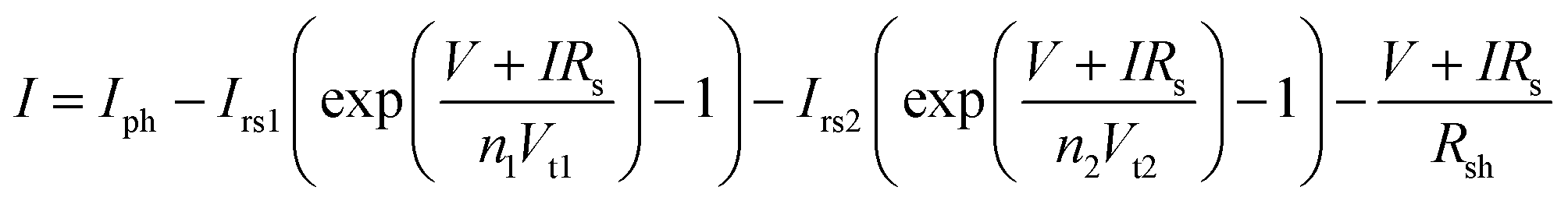 | (1) |
In contrast, applying these established strategies directly to perovskite solar cells has proven significantly more challenging. Primarily due to the inherently dynamic and transient nature of the PSCs degradation. Although two-diode equivalent circuit plus irradiance adjustment method-type model applications have been effective in silicon-module outdoor performance prediction, the respective applications on PSCs show markedly smaller success rates. Such lack of efficacy is a direct outcome stemming from the crucial difference in the mechanism of degradation. Silicon-based PV technology is predominantly affected by physical, electrochemical, and thermal degradation stemming from well-known mechanisms such as corrosion, microcrack formation, and potential-induced degradation (PID), with typical yearly performance losses of ∼0.5–0.6% under temperate climates.392,412 PSCs exhibit degradation driven by humidity and temperature dependent ionic migration, interfacial reactions, volatile species transport, and light-induced phase segregation.413 These processes introduce hysteresis, transient behavior, and path dependent degradation trajectories that violate the core assumptions of equivalent circuit-based models.
Another dimension to consider is the relative susceptibility of PSCs towards environmental degradation. Silicon modules benefit from decade-long advancements in the field of encapsulation technology capable of slowing moisture as well as oxygen penetration, which has enabled lifespans exceeding 25 years in modules. In contrast, PSCs are significantly more susceptible to minor defects in the encapsulation domain. Even in optimal conditions of encapsulation, native processes of degradation such as ionic migration may still pose a threat towards stability.414 Dynamic behaviors, partial reversible defect passivation under light, nocturnal relaxation, light soaking effects, and daily thermal/photofatigue cycling,415,416 complicate any attempt to map short-term indoor measurements to long-term field performance. These reversible-irreversible interactions challenge silicon derived models that assume monotonic and mechanism consistent degradation pathways.
These discrepancies explain why silicon PV modelling approaches must be modified for PSCs and why new strategies should account for PSC-specific transient and environmental degradation phenomena.
In addition to following the ISOS-D3 procedure for accelerated aging and extending IEC 61215: 2021, Kobayashi et al. performed 3000 hours of moist heat testing at 85 °C and 85% relative humidity.418 The T90 data showed an approximate T90 value of 3260 hours, which was then converted to a projected outdoor durability estimate of 20 years. This projection was based on benchmarks for silicon PV panel aging and therefore carries uncertainty when applied to PSCs, as the degradation mechanisms and environmental sensitivities differ substantially between the two technologies. Although this study demonstrates remarkable indoor durability and parallelism with silicon-based predictive models, the inherently nonlinear and transient degradation mechanisms of PSCs underscore the need for complementary testing approaches that account for the specific failure modes and sensitivities inherent to perovskite photovoltaics. In particular, the acceleration factors are inherited from silicon IEC protocols and are not calibrated against PSCs specific degradation kinetics, such as ion migration, bias induced interface reactions, or the sensitivity to humidity and temperature ramp rates. As a result, the 20-year estimate reflects equivalent stress severity, but not necessarily the same failure modes as those active under outdoor operation.
To achieve this objective, Hans Köbler and his team conducted a comparative analysis of constant illumination, light-cycle (LC), and outdoor testing methodologies with the aim of investigating the transient behaviors of PSCs.419 The study revealed significant discrepancies between indoor and outdoor test results attributable to transient effects. A correlation between indoor and outdoor performance was observed; however, the different behaviors could be attributed to variations in hole transport materials and their effect on device stability. Therefore, LC tests are not universally predictive, the development of improved testing protocols and robust encapsulation strategies is necessary to address correlation errors between indoor stability predictions and actual outdoor performance of PSCs. Mark Khenkin et al. reported a two-year outdoor stability study,133 demonstrating a strong correlation between LC tests and real-world outdoor performance. The research findings indicate that different PSC architectures manifest distinct behavioral patterns when subjected to stability testing. The triple cation/NiOx perovskite cells demonstrated a uniform decline in performance under both LC and outdoor conditions, supporting the suggestion that LC tests can reliably indicate long-term trends. The most stable dual-cation/SAM perovskite cells also performed well outdoors, with no significant degradation over a year. These results suggest that LC tests may reflect degradation caused by ion migration during night/day cycles better than traditional constant illumination experiments. Ulas Erdil et al. proposed an innovative accelerated aging protocol that applies a continuous forward bias in the dark, followed by a post-bias rest phase, to simulate migration-driven degradation typically observed under outdoor exposure conditions.152 Unlike conventional tests, this methodology reflects natural cycles and variations better, without needing illumination. It shows that forward polarization impairs charge transport by increasing recombination losses. There is some recovery during rest, but it also causes a decline. The degradation patterns in this indoor study are like those in an outdoor 20-month study in Berlin, showing that the method is relevant. This low-cost, non-illuminating strategy has the potential to be a promising alternative to conventional stress tests for assessing PSC stability. Together, these studies show that LC and bias-driven indoor tests can reproduce specific outdoor degradation signatures, mainly those linked to ion migration and transient interfacial processes, but their predictive value remains limited. The correlations observed are architecture dependent, and each protocol isolates only a subset of relevant stressors. None of the approaches incorporate real spectral variation, diurnal MPP transients, humidity or temperature ramping, or module-scale gradients. Thus, while mechanistically informative, these tests do not yet provide a complete basis for quantitative outdoor lifetime prediction, underscoring the need for multi-stressor, climate-relevant stability frameworks.
Simultaneously, Jiang et al. developed a temperature-dependent degradation model based on accelerated indoor testing under 1.2-sun illumination at temperatures ranging from 25 °C to 85 °C.132 Arrhenius analysis was applied to the data, resulting in an apparent activation energy of approximately 0.59 eV. Subsequently, the model was combined with recorded outdoor ambient temperature data, incorporating an estimated compensation for the internal temperature of the device of 40–50 °C, in order to calculate weekly degradation rates and predict cumulative performance losses under outdoor conditions. Over a 26-week period, the degradation trends showed a high degree of agreement with actual measurements, validating the use of indoor thermal stress testing to predict real-world behavior, provided the dominant degradation mechanism remains the same. To make standard accelerated stress tests more reflective of behavior in the real world, Song et al. highlights the importance of including the actual conditions of devices exposed to outdoor environments in indoor testing.36 The proposed method incorporates light and dark cycles, temperature variations, and other environmental elements relevant to outdoor operation. Additionally, the influence of perovskite composition on degradation was investigated, showing that during the night, FAMA-based solar cells self-recovered, while ion migration caused deterioration in FA/Cs-based devices during thermal cycles. This study proposes the development of real-world-like tests to increase the accuracy of degradation behavior across different perovskite compositions. These results show that temperature-activated indoor models can reproduce outdoor behavior only when the same dominant mechanism is active. However, as demonstrated by real world emulation protocols that include light/dark cycling, temperature variations, and composition dependent ion migration, can trigger mechanism changes that are not captured by purely temperature-based Arrhenius extrapolations. This confirms the need for accelerated indoor tests that integrate the full transient coupling of illumination, temperature, bias, and environmental factors to achieve robust outdoor predictability.
To improve the accuracy of indoor stability tests, Noor Titan et al. proposed a new indoor aging protocol to more accurately predict the long-term outdoor stability of PSCs.421 The study showed that traditional continuous illumination tests do not replicate real-world day–night cycling, so an accelerated aging method was introduced that combines elevated temperatures with shortened light/dark cycles. The improvement in the correlation between indoor and outdoor degradation behaviors is significant. An Arrhenius-based equation was presented for calculating cycle duration. This method provides a solid framework for simulating the degradation of PSCs. For example, the test has different cycle durations depending on the temperature: 12 hours of light/12 hours of darkness at 25 °C, but at 55 °C, the cycle is reduced to 1.5 hours of light/1.5 hours of darkness. The acceleration factor, which defines the rate at which the degradation cycle occurs relative to real-world conditions, ranged from 5× to 46×. This acceleration factor was obtained by increasing the temperature and reducing the cycle duration. Among the PSC architectures tested, those based on SAM showed the fastest degradation rate (46×), while NiOx-based PSCs and NiOx/SAM hybrids demonstrated significantly greater stability (∼5×). The model was validated on different hole transport layers in PIN architectures, demonstrating that degradation trends at higher temperatures with shorter cycles are like those at lower temperatures with longer cycles. This confirms the reliability of the estimation model (see Note S3).
The integration of illumination and temperature in these indoor protocols has been shown to enhance the predictive accuracy of the models. Furthermore, the incorporation of environment-dependent acceleration factors has been demonstrated to further improve the correspondence between the indoor and outdoor degradation trends. However, variable humidity and differences in perovskite composition can alter the dominant degradation mechanisms, especially in extreme climatic conditions where encapsulants may fail. This makes it necessary to validate data collected outdoors under variable climatic conditions, mainly in tropical climates with high UV, humidity changes, and constant high irradiance. This ensures the opportunity to adjust acceleration models to generalize and strengthen different environmental stress regimes.
Machine learning (ML) has been used to predict long-term PSC performance under real conditions. These methods use short-term testing to generate fast and accurate predictions. Unlike conventional models, these models could interpret the nonlinear and combined effects of stress factors present in outdoor conditions. Consequently, they facilitate the reduction of testing time, provide guidance on material and architecture optimization, and support the transferability of lifetime predictions across various climates and device configurations.
Graniero et al. conducted a comprehensive ML study using both the Perovskite Database Project and a high-resolution in-house aging dataset.422 The demonstration showed that nonlinear models, e.g., the Random Forest algorithm, can identify key elements that affect stability, such as perovskite composition, charge transport layers, and environmental exposure. Researchers emphasized the fundamental importance of a high-quality dataset for model accuracy. The study found no significant improvement with larger datasets if the data quality was not improved because there were inconsistencies among common aging data metrics. Standardized and high-quality datasets are needed to improve machine learning reliability and ML-based predictions should be validated against long-term outdoor datasets before being used as definitive lifetime estimations.
In a similar vein, Odabaşı and Yıldırım employed ML-based meta-analysis to analyze a curated dataset of 404 PSCs, which had been compiled from 181 publications.423 Subsequently, the researchers employed association rule mining and decision tree modeling, thereby identifying strategies such as mixed cations, multi-spin deposition, SnO2 as ETL, and storage at low humidity. This process yielded models with interpretable rules, such as high stability at <30% humidity. The study demonstrates the value of statistical learning in deriving practical design guidelines, although such guidelines are not yet developed to directly extrapolate outdoor lifetimes, and their applicability remains limited without controlled real-world validation.
To enhance the accuracy of ML models, Kouroudis et al. advanced the field by introducing a wavelet-assisted ML framework to quantitatively predict outdoor PSC degradation from short-term indoor aging tests.334 The methodology combines signal preprocessing, utilizing IIR filtering and Daubechies-2 wavelet transforms, with a Kernel Ridge Regression (KRR) model trained on time-series degradation data collected under controlled indoor conditions (varied light intensity, atmosphere, and temperature). To avoid overfitting, indoor tests were selected using the Fréchet distance metric. The model's robustness was enhanced using Bayesian optimization and six-fold cross-validation. The model predicted outdoor degradation behavior effectively (MSE < 0.24) across various climates, e.g., Barcelona and the Negev desert, but the predictions remain dependent on the representativeness of the indoor stress profiles used for training.
Consistent with this, a recent review of accelerated degradation models424 concluded that traditional single-stressor approaches such as Arrhenius or Eyring capture temperature-driven degradation but break down when humidity, light, or electrical bias introduce additional pathways. Humidity-driven degradation requires dual-stressor formulations like Hallberg-Peck, while PID follows inverse-power-law kinetics, and no single model can represent all coupled effects observed in real devices. The review therefore recommends the development of multi-variable degradation models, such as Arrhenius-light, Arrhenius-RH, or Subramaniyan-type conjunction models, that explicitly integrate temperature, humidity, illumination, and electrical bias within a unified acceleration framework to enable more realistic stability predictions under complex stress conditions.
ML also shows strong potential for improving outdoor prediction when supported by high-quality datasets. Current studies consistently demonstrate that accurate outdoor predictions are only possible when indoor training data capture the same dominant stress factors operating in the field. For example, Kouroudis et al.334 showed that 1-sun nitrogen tests yielded the lowest prediction error because the outdoor devices used for validation were encapsulated and therefore degraded mainly through thermal-ionic pathways; in contrast, indoor air tests performed more than twice as poorly, indicating that models trained under mismatched stress profiles fail to reproduce outdoor behavior. They also demonstrated that prediction of accuracy declines when indoor and outdoor protocols diverge, such as differences in UV shielding, highlighting the sensitivity of ML models to inconsistent stress environments. In practice, this means that ML models should be trained within the same degradation regime they are expected to predict, encapsulated outdoor devices require encapsulation-relevant indoor stress profiles, whereas unencapsulated devices demand training data that explicitly include air exposure, humidity, and UV.
In this context, a simplified but practical approach is for each laboratory to train ML models using its own indoor protocols, device architectures, and encapsulation strategies. Such lab-specific training can yield accurate predictions for that laboratory device, allowing ML to serve as a tool for forecasting outdoor performance under the specific conditions relevant to that fabrication line. In contrast, building a generalized, climate agnostic outdoor-prediction model requires structured dataset expansion. High-quality indoor measurements under controlled 1-sun illumination, varied temperatures, and well-defined atmospheres (N2vs. air) should form the core of the training set, recorded through stabilized MPP or PCE time series. Additional stressors should be included only when they correspond to realistic degradation pathways for the devices being modeled, such as humidity-driven changes, light/dark transients, seasonal effects (self-recovery), solar cells architectures, or composition-dependent ion migration. Additionally, given that machine learning predictions exhibited reduced accuracy when indoor and outdoor stress profiles diverged (e.g., UV exposure, imperfect encapsulation, moisture ingress), a subset of device data could comprise measurements that integrate indoor and outdoor measurements across disparate climate zones. The expansion of the diversity of datasets under controlled and well-adapted protocols is of greater value than the mere increase in size of the dataset. This is a prerequisite for machine learning models that aim to generalize across different laboratories and climate zones.
6. Conclusions and perspectives
Recent advancements in PSCs have shown encouraging results, with some studies reporting multi-year operational lifetimes. However, transitioning from laboratory success to large-scale and reliable outdoor deployment requires directly confronting several critical bottlenecks. While traditional performance benchmarks and indoor evaluation tests are useful for initial assessments, they still fail to capture the complexities of real-world conditions, such as fluctuating irradiance and temperature variations. Environmental and operational coupled factors, such as high humidity, extreme temperatures, UV exposure and bias play a significant role in different PSCs degradation mechanisms, and become very dependent on the specific location, as each climate presents unique fluctuations. This can be significantly understood by adequate modeling of coupled factors (e.g., simultaneous UV exposure, humidity, high temperature, and electrical bias), as recent advances in in situ and in-operando studies provide critical insights into these mechanisms, enabling a deeper understanding of interfacial reactions and paving the way for more rational design principles that enhance device robustness. While improvements in PSCs stability, such as those achieved through interface engineering and carbon-based back electrodes, show promise, their long-term viability under outdoor exposure conditions has not been fully validated yet, as required by industry. Therefore, research must pivot from laboratory tuning to a rational, physics-based approach for degradation mitigation. This involves leveraging these advanced in situ and in operando diagnostic tools to monitor interfacial reactions in real-time, enabling the design of intrinsically more robust bulk materials, highly stable interface layers, and self-healing or passivating encapsulation strategies. On the other hand, the diagnostic tools used in outdoor evaluations, such as thermal coefficients and I–V curve tracing, help to identify key degradation pathways, but they alone are not enough to fully predict long-term performance. Issues like insulation, leakage currents, and the formation of hot spots must also be addressed to ensure the durability and stability of PSCs modules. As most stability evaluations are still conducted under controlled environments, there is still a need for real-world testing. This gap in outdoor testing is especially prominent in regions like Latin America, Africa, and Southeast Asia, where climate-specific degradation mechanisms remain insufficiently understood. In general, more outdoor testing in tropical climates is required to collect data of PSC degradation under stringent climate conditions with consistent day/night cycles, serving as reference platforms for accelerated stability testing, material benchmarking and the development of robust commercial photovoltaic technologies, where other engineering issues (insulation breakdown, localized hot spots, and leakage currents) come out as area increases, limiting long-term durability and making more evident the performance and stability gap between small-area laboratory devices and commercial-sized modules. In this sense, more systematic outdoor evaluations of mini-modules, sub-modules, and full modules are needed to address scaling challenges and ensure reliable real-world performance characterization. However, even if these evaluations are currently being conducted, it takes several years to be reported to the community, which combined with a lack of clarity about which standard is most appropriate to report for specific cases, makes it difficult to compare materials and device architectures under different climatic conditions, reporting data across the community using agreed-upon testing protocols. Finally, by focusing research efforts from rational materials and devices design to standardized, geographically diverse outdoor validation, the field can transition from reporting promising laboratory results to delivering a truly viable, commercially scalable, and globally stable perovskite photovoltaic technology. The long road to outdoor stability demands a fundamental shift toward real-world testing and predictive engineering to fully unlock the transformative potential of PSCs.Disclaimer
We have used AI assistance to help with the English language formulation and some grammatical aspects. All technical points, Ideas, original text, and results in this review are our own original contributions provided in only some parts to the AI system. We have thoroughly written the entire review and verified that no information has been fabricated or misrepresented in the grammatical improvement process.Author contributions
J. J. P. L. and K. G. R. B. contributed equally to this work. All the authors wrote, analyzed and reviewed the manuscript.Conflicts of interest
The authors declare no competing financial interest.Data availability
All data supporting this study is included in the manuscript. All figures are original, created by the authors, and appropriately cited where external sources were used to support their illustrations.The data supporting this article have been included as part of the supplementary information (SI). Supplementary information is available, this document provides the Scopus-based literature review methodology and datasets (Tables S1–S3) for outdoor stability reports and manufacturing strategies. It includes technical specifications and 18-month environmental data from the Medellín monitoring station. Additionally, it offers practical guidelines for developing low-cost outdoor testing infrastructure. See DOI: https://doi.org/10.1039/d5cs01085c.
Acknowledgements
The authors are pleased to acknowledge ‘Estrategia de Sostenibilidad de la Universidad de Antioquia’ and the financial support of the ‘Sistema General de Regalías-SGR’ through project BPIN2023000100025 and the Ministry of Science, Technology, and Innovation (MinCiencias) through ‘Patrimonio Autónomo Fondo Nacional de Financiamiento para la Ciencia, la Tecnología y la Innovación, Francisco José de Caldas’ (Perseo Alliance, Contract No. 112721-392-2023)'.References
- C. Wang, Y. Ding, Y. Wang, Z. Xie, Z. Zeng, X. Li and Y. H. Ng, Metal halide perovskites for solar-to-chemical energy conversion in aqueous media, Carbon Energy, 2024, 6(11), e500, DOI:10.1002/cey2.500.
- X. Liu, D. Yu, X. Song and H. Zeng, Metal Halide Perovskites: Synthesis, Ion Migration, and Application in Field-Effect Transistors, Small, 2018, 14(36), 1801460, DOI:10.1002/smll.201801460.
- Y. Yang, Y. Yan, M. Yang, S. Choi, K. Zhu, J. M. Luther and M. C. Beard, Low surface recombination velocity in solution-grown CH3NH3PbBr3 perovskite single crystal, Nat. Commun., 2015, 6(1), 7961, DOI:10.1038/ncomms8961.
- H. Fu, Colloidal metal halide perovskite nanocrystals: a promising juggernaut in photovoltaic applications, J. Mater. Chem. A, 2019, 7(24), 14357–14379, 10.1039/C8TA12509K.
- J. S. Manser, J. A. Christians and P. V. Kamat, Intriguing Optoelectronic Properties of Metal Halide Perovskites, Chem. Rev., 2016, 116(21), 12956–13008, DOI:10.1021/acs.chemrev.6b00136.
- Z.-Y. Chen, N.-Y. Huang and Q. Xu, Metal halide perovskite materials in photocatalysis: Design strategies and applications, Coord. Chem. Rev., 2023, 481, 215031, DOI:10.1016/j.ccr.2023.215031.
- F. Zhang, H. Zhong, C. Chen, X. Wu, X. Hu, H. Huang, J. Han, B. Zou and Y. Dong, Brightly Luminescent and Color-Tunable Colloidal CH3NH3PbX3 (X = Br, I, Cl) Quantum Dots: Potential Alternatives for Display Technology, ACS Nano, 2015, 9(4), 4533–4542, DOI:10.1021/acsnano.5b01154.
- V. K. Ravi, G. B. Markad and A. Nag, Band Edge Energies and Excitonic Transition Probabilities of Colloidal CsPbX 3 (X = Cl, Br, I) Perovskite Nanocrystals, ACS Energy Lett., 2016, 1(4), 665–671, DOI:10.1021/acsenergylett.6b00337.
- G. Xing, N. Mathews, S. Sun, S. S. Lim, Y. M. Lam, M. Grätzel, S. Mhaisalkar and T. C. Sum, Long-Range Balanced Electron- and Hole-Transport Lengths in Organic–Inorganic CH3NH3PbI3, Science, 2013, 342(6156), 344–347, DOI:10.1126/science.1243167.
- National Renewable Energy Laboratory (NREL). Best Research-Cell Efficiency. https://www.nrel.gov/pv/cell-efficiency.html (accedido 2025-01-26).
- AIKO Solar. Romance Under Sunlight Smart New Home. https://aikosolar.com/en/homeowners/(accedido 2025-07-19).
- Jinko Solar. Tiger Neo. https://www.jinkosolar.com/en/site/tigerneo#s1 (accedido 2025-07-19).
- Space, A. 1.5 Million Cells in Space Without any Failures. https://www.azurspace.com/index.php/en/products/products-space/space-solar-cells (accedido 2025-07-19).
- First Solar. A High-Quality Thin Film CdTe Module Made in America, for America. https://www.firstsolar.com/en/Products/Series-7 (accedido 2025-07-19).
- BougeRV. Yuma 100W CIGS Thin-film Flexible Solar Panel (Square with Adhesive). https://au.bougerv.com/products/yuma-100w-cigs-flexible-solar-panel-with-adhesive (accedido 2025-07-19).
- C. Harito, S. A. Abrori, M. Khalil, B. Yuliarto and S. Erten-Ela, Current progress of perovskite solar cells stability with bibliometric study, Curr. Opin. Colloid Interface Sci., 2024, 74, 101862, DOI:10.1016/j.cocis.2024.101862.
- K.-L. Wang, X.-M. Li, Y.-H. Lou, M. Li and Z.-K. Wang, CsPbBrI2 perovskites with low energy loss for high-performance indoor and outdoor photovoltaics, Sci. Bull., 2021, 66(4), 347–353, DOI:10.1016/j.scib.2020.09.017.
- R. Azmi, N. Nurrosyid, S.-H. Lee, M. Al Mubarok, W. Lee, S. Hwang, W. Yin, T. K. Ahn, T.-W. Kim, D. Y. Ryu, Y. R. Do and S.-Y. Jang, Shallow and Deep Trap State Passivation for Low-Temperature Processed Perovskite Solar Cells, ACS Energy Lett., 2020, 5(5), 1396–1403, DOI:10.1021/acsenergylett.0c00596.
- H. Xie, Z. Wang, Z. Chen, C. Pereyra, M. Pols, K. Gałkowski, M. Anaya, S. Fu, X. Jia, P. Tang, D. J. Kubicki, A. Agarwalla, H.-S. Kim, D. Prochowicz, X. Borrisé, M. Bonn, C. Bao, X. Sun, S. M. Zakeeruddin, L. Emsley, J. Arbiol, F. Gao, F. Fu, H. I. Wang, K.-J. Tielrooij, S. D. Stranks, S. Tao, M. Grätzel, A. Hagfeldt and M. Lira-Cantu, Decoupling the effects of defects on efficiency and stability through phosphonates in stable halide perovskite solar cells, Joule, 2021, 5(5), 1246–1266, DOI:10.1016/j.joule.2021.04.003.
- Q. Jiang, Y. Zhao, X. Zhang, X. Yang, Y. Chen, Z. Chu, Q. Ye, X. Li, Z. Yin and J. You, Surface passivation of perovskite film for efficient solar cells, Nat. Photonics, 2019, 13(7), 460–466, DOI:10.1038/s41566-019-0398-2.
- C. Zhao, H. Zhang, A. Krishna, J. Xu and J. Yao, Interface Engineering for Highly Efficient and Stable Perovskite Solar Cells, Adv. Opt. Mater., 2024, 12(7), 2301949, DOI:10.1002/adom.202301949.
- J. Chen and N.-G. Park, Materials and Methods for Interface Engineering toward Stable and Efficient Perovskite Solar Cells, ACS Energy Lett., 2020, 5(8), 2742–2786, DOI:10.1021/acsenergylett.0c01240.
- A. Islam, S. Z. Haider, M. Wang, A. G. Ismail and H. Anwar, Interface engineering for improved performance of perovskite solar cells using CdTe buffer layer, Results Eng., 2024, 23, 102618, DOI:10.1016/j.rineng.2024.102618.
- H. Pan, H. Shao, X. L. Zhang, Y. Shen and M. Wang, Interface engineering for high-efficiency perovskite solar cells, J. Appl. Phys., 2021, 129(13), 130904, DOI:10.1063/5.0038073.
- S. P. Koiry, P. Jha, C. Sridevi, D. Gupta, V. Putta and A. K. Chauhan, Improved water repellency and environmental stability of perovskite solar cells by encapsulating with paraffin wax, Mater. Chem. Phys., 2022, 282, 125954, DOI:10.1016/j.matchemphys.2022.125954.
- M. Mohammadi, S. Gholipour, M. Malekshahi Byranvand, Y. Abdi, N. Taghavinia and M. Saliba, Encapsulation Strategies for Highly Stable Perovskite Solar Cells under Severe Stress Testing: Damp Heat, Freezing, and Outdoor Illumination Conditions, ACS Appl. Mater. Interfaces, 2021, 13(38), 45455–45464, DOI:10.1021/acsami.1c11628.
- G. Zhang, Y. Zheng, H. Wang, G. Ding, F. Yang, Y. Xu, J. Yu and Y. Shao, Shellac protects perovskite solar cell modules under real-world conditions, Joule, 2024, 8(2), 496–508, DOI:10.1016/j.joule.2023.12.008.
- S. Ma, G. Yuan, Y. Zhang, N. Yang, Y. Li and Q. Chen, Development of encapsulation strategies towards the commercialization of perovskite solar cells, Energy Environ. Sci., 2022, 15(1), 13–55, 10.1039/D1EE02882K.
- K. Aitola, G. Gava Sonai, M. Markkanen, J. Jaqueline Kaschuk, X. Hou, K. Miettunen and P. D. Lund, Encapsulation of commercial and emerging solar cells with focus on perovskite solar cells, Sol. Energy, 2022, 237, 264–283, DOI:10.1016/j.solener.2022.03.060.
- P. E. Burrows, V. Bulovic, S. R. Forrest, L. S. Sapochak, D. M. McCarty and M. E. Thompson, Reliability and degradation of organic light emitting devices, Appl. Phys. Lett., 1994, 65(23), 2922–2924, DOI:10.1063/1.112532.
- R. K. Raman, S. A. Gurusamy Thangavelu, S. Venkataraj and A. Krishnamoorthy, Materials, methods and strategies for encapsulation of perovskite solar cells: From past to present, Renew. Sustain. Energy Rev., 2021, 151, 111608, DOI:10.1016/j.rser.2021.111608.
- S. Jiang, K. Wang, H. Zhang, Y. Ding and Q. Yu, Encapsulation of PV Modules Using Ethylene Vinyl Acetate Copolymer as the Encapsulant, Macromol. React. Eng., 2015, 9(5), 522–529, DOI:10.1002/mren.201400065.
- M. U. Ali, H. Mo, Y. Li and A. B. Djurišić, Outdoor stability testing of perovskite solar cells: Necessary step toward real-life applications, APL Energy, 2023, 1(2), 020903, DOI:10.1063/5.0155845.
- J. Zhou, Y. Gao, Y. Pan, F. Ren, R. Chen, X. Meng, D. Sun, J. He, Z. Liu and W. Chen, Recent Advances in the Combined Elevated Temperature, Humidity, and Light Stability of Perovskite Solar Cells, Sol. RRL, 2022, 6(12), 2200772, DOI:10.1002/solr.202200772.
- D. Zhang, D. Li, Y. Hu, A. Mei and H. Han, Degradation pathways in perovskite solar cells and how to meet international standards, Commun. Mater., 2022, 3(1), 58, DOI:10.1038/s43246-022-00281-z.
- W. Song and T. Aernouts, Novel test scenarios needed to validate outdoor stability of perovskite solar cells, J. Phys. Energy, 2020, 2(2), 021003, DOI:10.1088/2515-7655/ab6008.
- R. K. Gupta, D. K. Kumar, V. Sudhakar, J. M. Beckedahl, A. Abate, E. A. Katz and I. Visoly-Fisher, Seasonal Effects on Outdoor Stability of Perovskite Solar Cells, Adv. Energy Mater., 2025, 15(8), 2403844, DOI:10.1002/aenm.202403844.
- M. O. Reese, S. A. Gevorgyan, M. Jørgensen, E. Bundgaard, S. R. Kurtz, D. S. Ginley, D. C. Olson, M. T. Lloyd, P. Morvillo, E. A. Katz, A. Elschner, O. Haillant, T. R. Currier, V. Shrotriya, M. Hermenau, M. Riede, R. Kirov, K. Trimmel, G. Rath, T. Inganäs, O. Zhang, F. Andersson, M. Tvingstedt, K. Lira-Cantu, M. Laird, D. McGuiness, C. Gowrisanker, S. (Jimmy), M. Pannone, M. Xiao, J. Hauch, R. Steim, D. M. DeLongchamp, R. Rösch, H. Hoppe, N. Espinosa, A. Urbina, G. Yaman-Uzunoglu, J.-B. Bonekamp, A. J. J. M. van Breemen, C. Girotto, E. Voroshazi and F. C. Krebs, Consensus stability testing protocols for organic photovoltaic materials and devices, Sol. Energy Mater. Sol. Cells, 2011, 95(5), 1253–1267, DOI:10.1016/j.solmat.2011.01.036.
- M. V. Khenkin, E. A. Katz, A. Abate, G. Bardizza, J. J. Berry, C. Brabec, F. Brunetti, V. Bulović, Q. Burlingame, A. Di Carlo, R. Cheacharoen, Y.-B. Cheng, A. Colsmann, S. Cros, K. Domanski, M. Dusza, C. J. Fell, S. R. Forrest, Y. Galagan, D. Di Girolamo, M. Grätzel, A. Hagfeldt, E. von Hauff, H. Hoppe, J. Kettle, H. Köbler, M. S. Leite, S. Liu, Y.-L. Loo, J. M. Luther, C.-Q. Ma, M. Madsen, M. Manceau, M. Matheron, M. McGehee, R. Meitzner, M. K. Nazeeruddin, A. F. Nogueira, Ç. Odabaşı, A. Osherov, N.-G. Park, M. O. Reese, F. De Rossi, M. Saliba, U. S. Schubert, H. J. Snaith, S. D. Stranks, W. Tress, P. A. Troshin, V. Turkovic, S. Veenstra, I. Visoly-Fisher, A. Walsh, T. Watson, H. Xie, R. Yıldırım, S. M. Zakeeruddin, K. Zhu and M. Lira-Cantu, Consensus statement for stability assessment and reporting for perovskite photovoltaics based on ISOS procedures, Nat. Energy, 2020, 5(1), 35–49, DOI:10.1038/s41560-019-0529-5.
- H. Zhu, S. Teale, M. N. Lintangpradipto, S. Mahesh, B. Chen, M. D. McGehee, E. H. Sargent and O. M. Bakr, Long-term operating stability in perovskite photovoltaics, Nat. Rev. Mater., 2023, 8(9), 569–586, DOI:10.1038/s41578-023-00582-w.
- The Perovskite Database. The Perovskite Database Project. https://www.perovskitedatabase.com/ (accedido 2025-03-04).
- R. Cheacharoen, N. Rolston, D. Harwood, K. A. Bush, R. H. Dauskardt and M. D. McGehee, Design and understanding of encapsulated perovskite solar cells to withstand temperature cycling, Energy Environ. Sci., 2018, 11(1), 144–150, 10.1039/C7EE02564E.
- P. Holzhey and M. Saliba, A full overview of international standards assessing the long-term stability of perovskite solar cells, J. Mater. Chem. A, 2018, 6(44), 21794–21808, 10.1039/C8TA06950F.
- X. Li, M. Tschumi, H. Han, S. S. Babkair, R. A. Alzubaydi, A. A. Ansari, S. S. Habib, M. K. Nazeeruddin, S. M. Zakeeruddin and M. Grätzel, Outdoor Performance and Stability under Elevated Temperatures and Long-Term Light Soaking of Triple-Layer Mesoporous Perovskite Photovoltaics, Energy Technol., 2015, 3(6), 551–555, DOI:10.1002/ente.201500045.
- Y. Hu, Y. Chu, Q. Wang, Z. Zhang, Y. Ming, A. Mei, Y. Rong and H. Han, Standardizing Perovskite Solar Modules beyond Cells, Joule, 2019, 3(9), 2076–2085, DOI:10.1016/j.joule.2019.08.015.
- M. Remec, M. Khenkin, U. Erdil, Q. Emery, G. Paramasivam, E. Unger, R. Schlatmann, S. Albrecht, M. Topič and C. Ulbrich, Seasonality in Perovskite Solar Cells: Insights from 4 Years of Outdoor Data, Adv. Energy Mater., 2025, 15(35), 2501906, DOI:10.1002/aenm.202501906.
- U. Erdil, M. Khenkin, W. M. Bernardes de Araujo, Q. Emery, I. Lauermann, V. Paraskeva, M. Norton, S. Vediappan, D. K. Kumar, R. K. Gupta, I. Visoly-Fisher, M. Hadjipanayi, G. E. Georghiou, R. Schlatmann, A. Abate, E. A. Katz and C. Ulbrich, Delamination of Perovskite Solar Cells in Thermal Cycling and Outdoor Tests, Energy Technol., 2025, 13(1), 2401280, DOI:10.1002/ente.202401280.
- A. M. A. Leguy, Y. Hu, M. Campoy-Quiles, M. I. Alonso, O. J. Weber, P. Azarhoosh, M. van Schilfgaarde, M. T. Weller, T. Bein, J. Nelson, P. Docampo and P. R. F. Barnes, Reversible Hydration of CH3NH3PbI3 in Films, Single Crystals, and Solar Cells, Chem. Mater., 2015, 27(9), 3397–3407, DOI:10.1021/acs.chemmater.5b00660.
- A. K. Chauhan and P. Kumar, Degradation in perovskite solar cells stored under different environmental conditions, J. Phys. D. Appl. Phys., 2017, 50(32), 325105, DOI:10.1088/1361-6463/aa7905.
- B. Conings, J. Drijkoningen, N. Gauquelin, A. Babayigit, J. D’Haen, L. D’Olieslaeger, A. Ethirajan, J. Verbeeck, J. Manca, E. Mosconi, F. De Angelis and H. Boyen, Intrinsic Thermal Instability of Methylammonium Lead Trihalide Perovskite, Adv. Energy Mater., 2015, 5(15), 1500477, DOI:10.1002/aenm.201500477.
- E. J. Juarez-Perez, L. K. Ono, I. Uriarte, E. J. Cocinero and Y. Qi, Degradation Mechanism and Relative Stability of Methylammonium Halide Based Perovskites Analyzed on the Basis of Acid–Base Theory, ACS Appl. Mater. Interfaces, 2019, 11(13), 12586–12593, DOI:10.1021/acsami.9b02374.
- Z. Ni, H. Jiao, C. Fei, H. Gu, S. Xu, Z. Yu, G. Yang, Y. Deng, Q. Jiang, Y. Liu, Y. Yan and J. Huang, Evolution of defects during the degradation of metal halide perovskite solar cells under reverse bias and illumination, Nat. Energy, 2021, 7(1), 65–73, DOI:10.1038/s41560-021-00949-9.
- Y. Yuan and J. Huang, Ion Migration in Organometal Trihalide Perovskite and Its Impact on Photovoltaic Efficiency and Stability, Acc. Chem. Res., 2016, 49(2), 286–293, DOI:10.1021/acs.accounts.5b00420.
- E. T. Hoke, D. J. Slotcavage, E. R. Dohner, A. R. Bowring, H. I. Karunadasa and M. D. McGehee, Reversible photo-induced trap formation in mixed-halide hybrid perovskites for photovoltaics, Chem. Sci., 2015, 6(1), 613–617, 10.1039/C4SC03141E.
- N. Li, Y. Luo, Z. Chen, X. Niu, X. Zhang, J. Lu, R. Kumar, J. Jiang, H. Liu, X. Guo, B. Lai, G. Brocks, Q. Chen, S. Tao, D. P. Fenning and H. Zhou, Microscopic Degradation in Formamidinium-Cesium Lead Iodide Perovskite Solar Cells under Operational Stressors, Joule, 2020, 4(8), 1743–1758, DOI:10.1016/j.joule.2020.06.005.
- E. J. Juarez-Perez, Z. Hawash, S. R. Raga, L. K. Ono and Y. Qi, Thermal degradation of CH3NH3PbI3 perovskite into NH3 and CH3I gases observed by coupled thermogravimetry–mass spectrometry analysis, Energy Environ. Sci., 2016, 9(11), 3406–3410, 10.1039/C6EE02016J.
- L. Lanzetta, T. Webb, N. Zibouche, X. Liang, D. Ding, G. Min, R. J. E. Westbrook, B. Gaggio, T. J. Macdonald, M. S. Islam and S. A. Haque, Degradation mechanism of hybrid tin-based perovskite solar cells and the critical role of tin (IV) iodide, Nat. Commun., 2021, 12(1), 2853, DOI:10.1038/s41467-021-22864-z.
- S. Baumann, G. E. Eperon, A. Virtuani, Q. Jeangros, D. B. Kern, D. Barrit, J. Schall, W. Nie, G. Oreski, M. Khenkin, C. Ulbrich, R. Peibst, J. S. Stein and M. Köntges, Stability and reliability of perovskite containing solar cells and modules: degradation mechanisms and mitigation strategies, Energy Environ. Sci., 2024, 17(20), 7566–7599, 10.1039/D4EE01898B.
- C. C. Boyd, R. Cheacharoen, T. Leijtens and M. D. McGehee, Understanding Degradation Mechanisms and Improving Stability of Perovskite Photovoltaics, Chem. Rev., 2019, 119(5), 3418–3451, DOI:10.1021/acs.chemrev.8b00336.
- N. Li, X. Niu, Q. Chen and H. Zhou, Towards commercialization: the operational stability of perovskite solar cells, Chem. Soc. Rev., 2020, 49(22), 8235–8286, 10.1039/D0CS00573H.
- L. Cai and F. Zhu, Toward efficient and stable operation of perovskite solar cells: Impact of sputtered metal oxide interlayers, Nano Sel., 2021, 2(8), 1417–1436, DOI:10.1002/nano.202000290.
- L. Duan, D. Walter, N. Chang, J. Bullock, D. Kang, S. P. Phang, K. Weber, T. White, D. Macdonald, K. Catchpole and H. Shen, Stability challenges for the commercialization of perovskite–silicon tandem solar cells, Nat. Rev. Mater., 2023, 8(4), 261–281, DOI:10.1038/s41578-022-00521-1.
- W. A. Dunlap-Shohl, Y. Zhou, N. P. Padture and D. B. Mitzi, Synthetic Approaches for Halide Perovskite Thin Films, Chem. Rev., 2019, 119(5), 3193–3295, DOI:10.1021/acs.chemrev.8b00318.
- Y. Zhao and K. Zhu, Organic–inorganic hybrid lead halide perovskites for optoelectronic and electronic applications, Chem. Soc. Rev., 2016, 45(3), 655–689, 10.1039/C4CS00458B.
- A. Buin, R. Comin, J. Xu, A. H. Ip and E. H. Sargent, Halide-Dependent Electronic Structure of Organolead Perovskite Materials, Chem. Mater., 2015, 27(12), 4405–4412, DOI:10.1021/acs.chemmater.5b01909.
- E. Fransson, J. M. Rahm, J. Wiktor and P. Erhart, Revealing the Free Energy Landscape of Halide Perovskites: Metastability and Transition Characters in CsPbBr3 and MAPbI3, Chem. Mater., 2023, 35(19), 8229–8238, DOI:10.1021/acs.chemmater.3c01740.
- N. Aristidou, C. Eames, I. Sanchez-Molina, X. Bu, J. Kosco, M. S. Islam and S. A. Haque, Fast oxygen diffusion and iodide defects mediate oxygen-induced degradation of perovskite solar cells, Nat. Commun., 2017, 8(1), 15218, DOI:10.1038/ncomms15218.
- M. Abbas, X. Xu, M. Rauf and A. K. K. Kyaw, A Comprehensive Review on Defects-Induced Voltage Losses and Strategies toward Highly Efficient and Stable Perovskite Solar Cells, Photonics, 2024, 11(1), 87, DOI:10.3390/photonics11010087.
- E. Velilla Hernández; J. Bernardo Cano Quintero; J. Felipe Montoya; I. Mora-Seró and F. Jaramillo Isaza, Outdoor Performance of Perovskite Photovoltaic Technology, Thin Films Photovoltaics, IntechOpen, 2022 DOI:10.5772/intechopen.100437.
- J. Tao, C. Zhao, Z. Wang, Y. Chen, L. Zang, G. Yang, Y. Bai and J. Chu, Suppressing non-radiative recombination for efficient and stable perovskite solar cells, Energy Environ. Sci., 2025, 18(2), 509–544, 10.1039/D4EE02917H.
- R. Li, Y. Luo, L. Yao, L. Tian, Z. Sun, R. Wang and J. Xue, Structural softness in photovoltaic perovskites, Appl. Phys. Lett., 2025, 126(14), 140501, DOI:10.1063/5.0256642.
- A. Srivastava and P. M. Shirage, Overcoming Intrinsic and Extrinsic Challenges in Perovskite Solar Cells: A Pathway Toward Advancement, 2024, pp. 55–89 DOI:10.1007/978-981-97-7624-5_2.
- H. Funk, T. Binyamin, L. Etgar, O. Shargaieva, T. Unold, A. Eljarrat, C. T. Koch and D. Abou-Ras, Phase Segregation Mechanisms in Mixed-Halide CsPb(BrxI1– x)3 Nanocrystals in Dependence of Their Sizes and Their Initial [Br]:[I] Ratios, ACS Mater. Au, 2023, 3(6), 687–698, DOI:10.1021/acsmaterialsau.3c00056.
- Y.-Y. Zhang, S. Chen, P. Xu, H. Xiang, X.-G. Gong, A. Walsh and S.-H. Wei, Intrinsic Instability of the Hybrid Halide Perovskite Semiconductor CH3NH3PbI3, Chinese Phys. Lett., 2018, 35(3), 036104, DOI:10.1088/0256-307X/35/3/036104.
- D. Bryant, N. Aristidou, S. Pont, I. Sanchez-Molina, T. Chotchunangatchaval, S. Wheeler, J. R. Durrant and S. A. Haque, Light and oxygen induced degradation limits the operational stability of methylammonium lead triiodide perovskite solar cells, Energy Environ. Sci., 2016, 9(5), 1655–1660, 10.1039/C6EE00409A.
- Y. Bai, R. Tian, K. Sun, C. Liu, X. Lang, M. Yang, Y. Meng, C. Xiao, Y. Wang, X. Lu, J. Wang, H. Pan, Z. Song, S. Zhou and Z. Ge, Decoupling light- and oxygen-induced degradation mechanisms of Sn–Pb perovskites in all perovskite tandem solar cells, Energy Environ. Sci., 2024, 17(22), 8557–8569, 10.1039/D4EE02427C.
- S. Bitton and N. Tessler, Perovskite ionics – elucidating degradation mechanisms in perovskite solar cells via device modelling and iodine chemistry, Energy Environ. Sci., 2023, 16(6), 2621–2628, 10.1039/D3EE00881A.
- B. Brunetti, C. Cavallo, A. Ciccioli, G. Gigli and A. Latini, On the Thermal and Thermodynamic (In)Stability of Methylammonium Lead Halide Perovskites, Sci. Rep., 2016, 6(1), 31896, DOI:10.1038/srep31896.
- A. Dualeh, P. Gao, S. I. Seok, M. K. Nazeeruddin and M. Grätzel, Thermal Behavior of Methylammonium Lead-Trihalide Perovskite Photovoltaic Light Harvesters, Chem. Mater., 2014, 26(21), 6160–6164, DOI:10.1021/cm502468k.
- J.-W. Lee, S. Tan, S. I. Seok, Y. Yang and N.-G. Park, Rethinking the A cation in halide perovskites, Science, 2022, 375(6583), eabj1186, DOI:10.1126/science.abj1186.
- X. Liu, D. Luo, Z.-H. Lu, J. S. Yun, M. Saliba, S. I. Seok and W. Zhang, Stabilization of photoactive phases for perovskite photovoltaics, Nat. Rev. Chem., 2023, 7(7), 462–479, DOI:10.1038/s41570-023-00492-z.
- Y. Liang, F. Li, X. Cui, T. Lv, C. Stampfl, S. P. Ringer, X. Yang, J. Huang and R. Zheng, Toward stabilization of formamidinium lead iodide perovskites by defect control and composition engineering, Nat. Commun., 2024, 15(1), 1707, DOI:10.1038/s41467-024-46044-x.
- M. Saliba, T. Matsui, J.-Y. Seo, K. Domanski, J.-P. Correa-Baena, M. K. Nazeeruddin, S. M. Zakeeruddin, W. Tress, A. Abate, A. Hagfeldt and M. Grätzel, Cesium-containing triple cation perovskite solar cells: improved stability, reproducibility and high efficiency, Energy Environ. Sci., 2016, 9(6), 1989–1997, 10.1039/C5EE03874J.
- G. Grancini, C. Roldán-Carmona, I. Zimmermann, E. Mosconi, X. Lee, D. Martineau, S. Narbey, F. Ostwald, F. De Angelis, M. Graetzel and M. K. Nazeeruddin, One-Year stable perovskite solar cells by 2D/3D interface engineering, Nat. Commun., 2017, 8(1), 15684, DOI:10.1038/ncomms15684.
- N. K. Noel, S. D. Stranks, A. Abate, C. Wehrenfennig, S. Guarnera, A.-A. Haghighirad, A. Sadhanala, G. E. Eperon, S. K. Pathak, M. B. Johnston, A. Petrozza, L. M. Herz and H. J. Snaith, Lead-free organic–inorganic tin halide perovskites for photovoltaic applications, Energy Environ. Sci., 2014, 7(9), 3061–3068, 10.1039/C4EE01076K.
- E. J. Juarez-Perez, L. K. Ono and Y. Qi, Thermal degradation of formamidinium based lead halide perovskites into sym -triazine and hydrogen cyanide observed by coupled thermogravimetry-mass spectrometry analysis, J. Mater. Chem. A, 2019, 7(28), 16912–16919, 10.1039/C9TA06058H.
- I. Ciria-Ramos, N. Navascués, F. Diaw, C. Furgeaud, R. Arenal, A. Ansón-Casaos, M. Haro and E. J. Juarez-Perez, Formamidinium halide salts as precursors of carbon nitrides, Carbon, 2022, 196, 1035–1046, DOI:10.1016/j.carbon.2022.05.051.
- W. Deng, J. Wei, Z. Ma and W. Feng, Research Progress on Stability of FAPbI3 Perovskite Solar Cells, Cryst. Res. Technol., 2025, 60(2), 2400228, DOI:10.1002/crat.202400228.
- D. P. McMeekin, G. Sadoughi, W. Rehman, G. E. Eperon, M. Saliba, M. T. Hörantner, A. Haghighirad, N. Sakai, L. Korte, B. Rech, M. B. Johnston, L. M. Herz and H. J. Snaith, A mixed-cation lead mixed-halide perovskite absorber for tandem solar cells, Science, 2016, 351(6269), 151–155, DOI:10.1126/science.aad5845.
- Z. Li, M. Yang, J.-S. Park, S.-H. Wei, J. J. Berry and K. Zhu, Stabilizing Perovskite Structures by Tuning Tolerance Factor: Formation of Formamidinium and Cesium Lead Iodide Solid-State Alloys, Chem. Mater., 2016, 28(1), 284–292, DOI:10.1021/acs.chemmater.5b04107.
- H. Yun, Y. Seo, C. Seo, H. S. Kim, S. B. Yoo, B. J. Kang, N. J. Jeon and E. H. Jung, Surface Engineering of Tin Oxide Nanoparticles by pH Modulation Facilitates Homogeneous Film Formation for Efficient Perovskite Solar Modules, Adv. Energy Mater., 2024, 14(25), 2400791, DOI:10.1002/aenm.202400791.
- C. Huang, S. Tan, B. Yu, Y. Li, J. Shi, H. Wu, Y. Luo, D. Li and Q. Meng, Meniscus-modulated blade coating enables high-quality α-phase formamidinium lead triiodide crystals and efficient perovskite minimodules, Joule, 2024, 8(9), 2539–2553, DOI:10.1016/j.joule.2024.06.008.
- C. Fei, A. Kuvayskaya, X. Shi, M. Wang, Z. Shi, H. Jiao, T. J. Silverman, M. Owen-Bellini, Y. Dong, Y. Xian, R. Scheidt, X. Wang, G. Yang, H. Gu, N. Li, C. J. Dolan, Z. J. D. Deng, D. N. Cakan, D. P. Fenning, Y. Yan, M. C. Beard, L. T. Schelhas, A. Sellinger and J. Huang, Strong-bonding hole-transport layers reduce ultraviolet degradation of perovskite solar cells, Science, 2024, 384(6700), 1126–1134, DOI:10.1126/science.adi4531.
- R. Cheacharoen, C. C. Boyd, G. F. Burkhard, T. Leijtens, J. A. Raiford, K. A. Bush, S. F. Bent and M. D. McGehee, Encapsulating perovskite solar cells to withstand damp heat and thermal cycling, Sustain. Energy Fuels, 2018, 2(11), 2398–2406, 10.1039/C8SE00250A.
- E. Ramírez; R. Betancur; J. Montoya; E. Velilla; D. Ramírez and F. Jaramillo, Encapsulation against Extrinsic Degradation Factors and Stability Testing of Perovskite Solar Cells, Recent Advances in Multifunctional Perovskite Materials, IntechOpen, 2022 DOI:10.5772/intechopen.106055.
- K. Choi, J. Lee, H. Choi, G.-W. Kim, H. I. Kim and T. Park, Heat dissipation effects on the stability of planar perovskite solar cells, Energy Environ. Sci., 2020, 13(12), 5059–5067, 10.1039/D0EE02859B.
- L. Wu, S. Hu, F. Yang, G. Li, J. Wang, W. Zuo, J. J. Jerónimo-Rendon, S.-H. Turren-Cruz, M. Saba, M. Saliba, M. K. Nazeeruddin, J. Pascual, M. Li and A. Abate, Resilience pathways for halide perovskite photovoltaics under temperature cycling, Nat. Rev. Mater., 2025, 10(7), 536–549, DOI:10.1038/s41578-025-00781-7.
- M. Jørgensen, K. Norrman and F. C. Krebs, Stability/degradation of polymer solar cells, Sol. Energy Mater. Sol. Cells, 2008, 92(7), 686–714, DOI:10.1016/j.solmat.2008.01.005.
- T. Malinauskas, D. Tomkute-Luksiene, R. Sens, M. Daskeviciene, R. Send, H. Wonneberger, V. Jankauskas, I. Bruder and V. Getautis, Enhancing Thermal Stability and Lifetime of Solid-State Dye-Sensitized Solar Cells via Molecular Engineering of the Hole-Transporting Material Spiro-OMeTAD, ACS Appl. Mater. Interfaces, 2015, 7(21), 11107–11116, DOI:10.1021/am5090385.
- P. Deng, W. Dai, Y. Gou, W. Zhang, Z. Xiao, S. He, X. Xie, K. Zhang, J. Li, X. Wang and L. Lin, Improving Thermal Stability of High-Efficiency Methylammonium-Free Perovskite Solar Cells via Chloride Additive Engineering, ACS Appl. Mater. Interfaces, 2024, 16(22), 29338–29346, DOI:10.1021/acsami.4c01335.
- T. Nie, Z. Fang, J. Ding and S. Liu (Frank), Improving the efficiency and stability of nickel oxide perovskite solar cells with doping and surface treatment strategies, Device, 2024, 2(10), 100498, DOI:10.1016/j.device.2024.100498.
- G. Divitini, S. Cacovich, F. Matteocci, L. Cinà, A. Di Carlo and C. Ducati, In situ observation of heat-induced degradation of perovskite solar cells, Nat. Energy, 2016, 1(2), 15012, DOI:10.1038/nenergy.2015.12.
- T. Zhang, H. Chen, Y. Bai, S. Xiao, L. Zhu, C. Hu, Q. Xue and S. Yang, Understanding the relationship between ion migration and the anomalous hysteresis in high-efficiency perovskite solar cells: A fresh perspective from halide substitution, Nano Energy, 2016, 26, 620–630, DOI:10.1016/j.nanoen.2016.05.052.
- Y. Kato, L. K. Ono, M. V. Lee, S. Wang, S. R. Raga and Y. Qi, Silver Iodide Formation in Methyl Ammonium Lead Iodide Perovskite Solar Cells with Silver Top Electrodes, Adv. Mater. Interfaces, 2015, 2(13), 1500195, DOI:10.1002/admi.201500195.
- Z. Zhang, H. Wang, T. J. Jacobsson and J. Luo, Big data driven perovskite solar cell stability analysis, Nat. Commun., 2022, 13(1), 7639, DOI:10.1038/s41467-022-35400-4.
- J. Ruellou, M. Courty and F. Sauvage, Thermal and Photo-Degradation Study of α -FAPbI3 -Based Perovskite Using In Situ X-Ray Diffraction, Adv. Funct. Mater., 2023, 33(34), 2300811, DOI:10.1002/adfm.202300811.
- S.-W. Lee, S. Kim, S. Bae, K. Cho, T. Chung, L. E. Mundt, S. Lee, S. Park, H. Park, M. C. Schubert, S. W. Glunz, Y. Ko, Y. Jun, Y. Kang, H.-S. Lee and D. Kim, UV Degradation and Recovery of Perovskite Solar Cells, Sci. Rep., 2016, 6(1), 38150, DOI:10.1038/srep38150.
- F. Lang, O. Shargaieva, V. V. Brus, H. C. Neitzert, J. Rappich and N. H. Nickel, Influence of Radiation on the Properties and the Stability of Hybrid Perovskites, Adv. Mater., 2018, 30(3), 1702905, DOI:10.1002/adma.201702905.
- Z. Wang, Z. Zhang, L. Xie, S. Wang, C. Yang, C. Fang and F. Hao, Recent Advances and Perspectives of Photostability for Halide Perovskite Solar Cells, Adv. Opt. Mater., 2022, 10(3), 2101822, DOI:10.1002/adom.202101822.
- H. Tsai, R. Asadpour, J.-C. Blancon, C. C. Stoumpos, O. Durand, J. W. Strzalka, B. Chen, R. Verduzco, P. M. Ajayan, S. Tretiak, J. Even, M. A. Alam, M. G. Kanatzidis, W. Nie and A. D. Mohite, Light-induced lattice expansion leads to high-efficiency perovskite solar cells, Science, 2018, 360(6384), 67–70, DOI:10.1126/science.aap8671.
- J. Zhuang, J. Wang and F. Yan, Review on Chemical Stability of Lead Halide Perovskite Solar Cells, Nano-Micro Lett., 2023, 15(1), 84, DOI:10.1007/s40820-023-01046-0.
- J. W. Schall, S. Johnston, K. Schutt, L. Chen, A. Palmstrom, M. Al-Jassim and D. B. Kern, In Situ Luminescence Imaging of Perovskite Solar Cells Demonstrates Increasing Spatial Nonuniformity upon Light-Soaking Degradation. En 2024 IEEE 52nd Photovoltaic Specialist Conference (PVSC), IEEE, 2024, pp 1591–1593 DOI:10.1109/PVSC57443.2024.10748989.
- K. Frohna, C. Chosy, A. Al-Ashouri, F. Scheler, Y.-H. Chiang, M. Dubajic, J. E. Parker, J. M. Walker, L. Zimmermann, T. A. Selby, Y. Lu, B. Roose, S. Albrecht, M. Anaya and S. D. Stranks, The impact of interfacial quality and nanoscale performance disorder on the stability of alloyed perovskite solar cells, Nat. Energy, 2024, 10(1), 66–76, DOI:10.1038/s41560-024-01660-1.
- R. E. Brandt, J. R. Poindexter, P. Gorai, R. C. Kurchin, R. L. Z. Hoye, L. Nienhaus, M. W. B. Wilson, J. A. Polizzotti, R. Sereika, R. Žaltauskas, L. C. Lee, J. L. MacManus-Driscoll, M. Bawendi, V. Stevanović and T. Buonassisi, Searching for “Defect-Tolerant” Photovoltaic Materials: Combined Theoretical and Experimental Screening, Chem. Mater., 2017, 29(11), 4667–4674, DOI:10.1021/acs.chemmater.6b05496.
- J. Ruellou, H. Ahouari, M. Courty, H. Vezin and F. Sauvage, Thermal and photodegradation mechanism of (FA-MA)PbI3 perovskite and spiro-OMeTAD captured by in situ EPR spectroscopy, EES Sol., 2025, 1(2), 172–181, 10.1039/D4EL00003J.
- T. Leijtens, K. Bush, R. Cheacharoen, R. Beal, A. Bowring and M. D. McGehee, Towards enabling stable lead halide perovskite solar cells; interplay between structural, environmental, and thermal stability, J. Mater. Chem. A, 2017, 5(23), 11483–11500, 10.1039/C7TA00434F.
- J. Huang, S. Tan, P. D. Lund and H. Zhou, Impact of H2O on organic–inorganic hybrid perovskite solar cells, Energy Environ. Sci., 2017, 10(11), 2284–2311, 10.1039/C7EE01674C.
- J. A. Christians, P. A. Miranda Herrera and P. V. Kamat, Transformation of the Excited State and Photovoltaic Efficiency of CH3NH3PbI3 Perovskite upon Controlled Exposure to Humidified Air, J. Am. Chem. Soc., 2015, 137(4), 1530–1538, DOI:10.1021/ja511132a.
- J. Yang, B. D. Siempelkamp, D. Liu and T. L. Kelly, Investigation of CH3NH3PbI3 Degradation Rates and Mechanisms in Controlled Humidity Environments Using in Situ Techniques, ACS Nano, 2015, 9(2), 1955–1963, DOI:10.1021/nn506864k.
- D. Yu, Y.-Q. Yang, Z. Chen, Y. Tao and Y.-F. Liu, Recent progress on thin-film encapsulation technologies for organic electronic devices, Opt. Commun., 2016, 362, 43–49, DOI:10.1016/j.optcom.2015.08.021.
- Y. Wang, I. Ahmad, T. Leung, J. Lin, W. Chen, F. Liu, A. M. C. Ng, Y. Zhang and A. B. Djurišić, Encapsulation and Stability Testing of Perovskite Solar Cells for Real Life Applications, ACS Mater. Au, 2022, 2(3), 215–236, DOI:10.1021/acsmaterialsau.1c00045.
- J. Y. Ye, R. A. Kerner, Q. Jiang, F. Yang, J. Yang, M. Ahmadi, S. P. Harvey, K. X. Steirer, D. Kuciauskas, J. J. Berry and K. Zhu, In situ formation of pseudohalide anions induced by humid air and light passivates formamidinium-based halide perovskites, InfoMat, 2025, 7(2), e12643, DOI:10.1002/inf2.12643.
- R. M. D’Souza, O. I. Onumonu, B. N. Lehtonen and T. L. Kelly, Humidity Resistance of Inverted Perovskite Solar Cells as Measured by Operando X-ray Scattering, ACS Appl. Energy Mater., 2024, 7(21), 9682–9688, DOI:10.1021/acsaem.4c02470.
- S. Mejaouri, S. Cacovich, P. Baranek, B. Bérenguier, I. Zimmermann, A. Yaiche, D. Loisnard, J. Rousset and S. Collin, Humidity-Induced Degradation Processes of Halide Perovskites Unveiled by Correlative Analytical Electron Microscopy, Small Methods, 2024, 8(1), 202300901, DOI:10.1002/smtd.202300901.
- N. Aristidou, I. Sanchez-Molina, T. Chotchuangchutchaval, M. Brown, L. Martinez, T. Rath and S. A. Haque, The Role of Oxygen in the Degradation of Methylammonium Lead Trihalide Perovskite Photoactive Layers, Angew. Chem., Int. Ed., 2015, 54(28), 8208–8212, DOI:10.1002/anie.201503153.
- W. R. Mateker and M. D. McGehee, Progress in Understanding Degradation Mechanisms and Improving Stability in Organic Photovoltaics, Adv. Mater., 2017, 29(10), 1603940, DOI:10.1002/adma.201603940.
- M. Jørgensen, K. Norrman, S. A. Gevorgyan, T. Tromholt, B. Andreasen and F. C. Krebs, Stability of Polymer Solar Cells, Adv. Mater., 2012, 24(5), 580–612, DOI:10.1002/adma.201104187.
- P. Docampo, S. Guldin, T. Leijtens, N. K. Noel, U. Steiner and H. J. Snaith, Lessons Learned: From Dye-Sensitized Solar Cells to All-Solid-State Hybrid Devices, Adv. Mater., 2014, 26(24), 4013–4030, DOI:10.1002/adma.201400486.
- N. J. F. Dodd and A. N. Jha, Photoexcitation of Aqueous Suspensions of Titanium Dioxide Nanoparticles: An Electron Spin Resonance Spin Trapping Study of Potentially Oxidative Reactions, Photochem. Photobiol., 2011, 87(3), 632–640, DOI:10.1111/j.1751-1097.2011.00897.x.
- W. Li, W. Zhang, S. Van Reenen, R. J. Sutton, J. Fan, A. A. Haghighirad, M. B. Johnston, L. Wang and H. J. Snaith, Enhanced UV-light stability of planar heterojunction perovskite solar cells with caesium bromide interface modification, Energy Environ. Sci., 2016, 9(2), 490–498, 10.1039/C5EE03522H.
- J. A. Christians, P. Schulz, J. S. Tinkham, T. H. Schloemer, S. P. Harvey, B. J. Tremolet de Villers, A. Sellinger, J. J. Berry and J. M. Luther, Tailored interfaces of unencapsulated perovskite solar cells for >1000 hour operational stability, Nat. Energy, 2018, 3(1), 68–74, DOI:10.1038/s41560-017-0067-y.
- Q. Jiang, R. Tirawat, R. A. Kerner, E. A. Gaulding, Y. Xian, X. Wang, J. M. Newkirk, Y. Yan, J. J. Berry and K. Zhu, Towards linking lab and field lifetimes of perovskite solar cells, Nature, 2023, 623(7986), 313–318, DOI:10.1038/s41586-023-06610-7.
- M. Khenkin, H. Köbler, M. Remec, R. Roy, U. Erdil, J. Li, N. Phung, G. Adwan, G. Paramasivam, Q. Emery, E. Unger, R. Schlatmann, C. Ulbrich and A. Abate, Light cycling as a key to understanding the outdoor behaviour of perovskite solar cells, Energy Environ. Sci., 2024, 17(2), 602–610, 10.1039/D3EE03508E.
- G. S. Kinsey, Solar cell efficiency divergence due to operating spectrum variation, Sol. Energy, 2021, 217, 49–57, DOI:10.1016/j.solener.2021.01.024.
- A. Kamppinen, H. Palonen and K. Miettunen, Self-Heating of Planar Perovskite Solar Cells Depending on Active Material Properties, ACS Appl. Energy Mater., 2024, 7(10), 4324–4334, DOI:10.1021/acsaem.4c00077.
- X. Cui, Q. Ruan, X. Zhuo, X. Xia, J. Hu, R. Fu, Y. Li, J. Wang and H. Xu, Photothermal Nanomaterials: A Powerful Light-to-Heat Converter, Chem. Rev., 2023, 123(11), 6891–6952, DOI:10.1021/acs.chemrev.3c00159.
- Y. Zhou, B. Wu, G. Lin, Z. Xing, S. Li, L. Deng, D. Chen, D. Yun and S. Xie, Interfacing Pristine C60 onto TiO2 for Viable Flexibility in Perovskite Solar Cells by a Low-Temperature All-Solution Process, Adv. Energy Mater., 2018, 8(20), 1800399, DOI:10.1002/aenm.201800399.
- H. Sun, J. Weickert, H. C. Hesse and L. Schmidt-Mende, UV light protection through TiO2 blocking layers for inverted organic solar cells, Sol. Energy Mater. Sol. Cells, 2011, 95(12), 3450–3454, DOI:10.1016/j.solmat.2011.08.004.
- M. H. Miah, M. B. Rahman, M. Nur-E-Alam, M. A. Islam, M. Shahinuzzaman, M. R. Rahman, M. H. Ullah and M. U. Khandaker, Key degradation mechanisms of perovskite solar cells and strategies for enhanced stability: issues and prospects, RSC Adv., 2025, 15(1), 628–654, 10.1039/D4RA07942F.
- H. M. Alishah, F. P. G. Choi and S. Gunes, Investigation of Various Commercial PEDOT:PSS (Poly(3,4-Ethylenedioxythiophene)Polystyrene Sulfonate) As A Hole Transport Layer in Lead Iodide Based Inverted Planar Perovskite Solar Cells. marzo 5, 2021 DOI:10.21203/rs.3.rs-269998/v1.
- J. W. Yang, R. H. Jeong and J.-H. Boo, Enhancement of UV-light harvesting in perovskite solar cells by internal down-conversion with Eu-complex hole transport layer, Energy Rep., 2022, 8, 214–222, DOI:10.1016/j.egyr.2022.08.125.
- V. Singh and T. Kumar, Study of modified PEDOT:PSS for tuning the optical properties of its conductive thin films, J. Sci. Adv. Mater. Devices, 2019, 4(4), 538–543, DOI:10.1016/j.jsamd.2019.08.009.
- M. B. Islam, M. Yanagida, Y. Shirai, Y. Nabetani and K. Miyano, Highly stable semi-transparent MAPbI3 perovskite solar cells with operational output for 4000 h, Sol. Energy Mater. Sol. Cells, 2019, 195, 323–329, DOI:10.1016/j.solmat.2019.03.004.
- J. Zhou, Z. Liu, P. Yu, G. Tong, R. Chen, L. K. Ono, R. Chen, H. Wang, F. Ren, S. Liu, J. Wang, Z. Lan, Y. Qi and W. Chen, Modulation of perovskite degradation with multiple-barrier for light-heat stable perovskite solar cells, Nat. Commun., 2023, 14(1), 6120, DOI:10.1038/s41467-023-41856-9.
- NASA. NASA Prediction of Worldwide Energy Resources (POWER). https://power.larc.nasa.gov/data-access-viewer/.
- R. Gehlhaar, T. Merckx, W. Qiu and T. Aernouts, Outdoor Measurement and Modeling of Perovskite Module Temperatures, Glob. Challenges, 2018, 2(7), 1800008, DOI:10.1002/gch2.201800008.
- R. A. Z. Razera, D. A. Jacobs, F. Fu, P. Fiala, M. Dussouillez, F. Sahli, T. C. J. Yang, L. Ding, A. Walter, A. F. Feil, H. I. Boudinov, S. Nicolay, C. Ballif and Q. Jeangros, Instability of p–i–n perovskite solar cells under reverse bias, J. Mater. Chem. A, 2020, 8(1), 242–250, 10.1039/C9TA12032G.
- D. B. Khadka, M. Yanagida and Y. Shirai, Assessing degradation in perovskite solar cells via thermal hysteresis of photocurrent and device simulation, Sol. Energy Mater. Sol. Cells, 2025, 281, 113319, DOI:10.1016/j.solmat.2024.113319.
- X. Zhang, X. Chen, Y. Chen, N. A. Nadege Ouedraogo, J. Li, X. Bao, C. B. Han, Y. Shirai, Y. Zhang and H. Yan, Rapid degradation behavior of encapsulated perovskite solar cells under light, bias voltage or heat fields, Nanoscale Adv., 2021, 3(21), 6128–6137, 10.1039/D1NA00495F.
- B. Chen, J. Song, X. Dai, Y. Liu, P. N. Rudd, X. Hong and J. Huang, Synergistic Effect of Elevated Device Temperature and Excess Charge Carriers on the Rapid Light-Induced Degradation of Perovskite Solar Cells, Adv. Mater., 2019, 31(35), 1902413, DOI:10.1002/adma.201902413.
- K. Domanski, B. Roose, T. Matsui, M. Saliba, S.-H. Turren-Cruz, J.-P. Correa-Baena, C. R. Carmona, G. Richardson, J. M. Foster, F. De Angelis, J. M. Ball, A. Petrozza, N. Mine, M. K. Nazeeruddin, W. Tress, M. Grätzel, U. Steiner, A. Hagfeldt and A. Abate, Migration of cations induces reversible performance losses over day/night cycling in perovskite solar cells, Energy Environ. Sci., 2017, 10(2), 604–613, 10.1039/C6EE03352K.
- U. Erdil, M. Khenkin, M. Remec, Q. Emery, V. Sudhakar, R. Schlatmann, A. Abate, E. A. Katz and C. Ulbrich, Mimicking Outdoor Ion Migration in Perovskite Solar Cells: A Forward Bias, No-Light Accelerated Aging Approach, ACS Energy Lett., 2025, 10(3), 1529–1537, DOI:10.1021/acsenergylett.5c00376.
- L. Nakka, W. Luo, A. G. Aberle and F. Lin, Study of Potential-Induced Degradation in Glass-Encapsulated Perovskite Solar Cells under Different Stress Conditions, Sol. RRL, 2023, 7(12), 2300100, DOI:10.1002/solr.202300100.
- F. Baumann, M. Karimipour, J. Padilla-Pantoja, E. Chávez-Angel, J. M. Caicedo Roque, R. Pouteaux, A. Alcalá Ibarra, S. Raga, J. Santiso and M. Lira-Cantu, Strain in Halide Perovskites and Solar Cell Stability: Accelerated Stress Tests under Bias Voltage, ACS Energy Lett., 2025, 10(1), 476–483, DOI:10.1021/acsenergylett.4c02822.
- X. Zhao, T. Liu, Q. C. Burlingame, T. Liu, R. Holley, G. Cheng, N. Yao, F. Gao and Y.-L. Loo, Accelerated aging of all-inorganic, interface-stabilized perovskite solar cells, Science, 2022, 377(6603), 307–310, DOI:10.1126/science.abn5679.
- D. S. Gets, G. A. Verkhogliadov, E. Y. Danilovskiy, A. I. Baranov, S. V. Makarov and A. A. Zakhidov, Dipolar cation accumulation at the interfaces of perovskite light-emitting solar cells, J. Mater. Chem. C, 2020, 8(47), 16992–16999, 10.1039/D0TC02654A.
- D. Moia, I. Gelmetti, P. Calado, Y. Hu, X. Li, P. Docampo, J. de Mello, J. Maier, J. Nelson and P. R. F. Barnes, Dynamics of Internal Electric Field Screening in Hybrid Perovskite Solar Cells Probed Using Electroabsorption, Phys. Rev. Appl., 2022, 18(4), 044056, DOI:10.1103/PhysRevApplied.18.044056.
- P. Lopez-Varo, J. A. Jiménez-Tejada, M. García-Rosell, J. A. Anta, S. Ravishankar, A. Bou and J. Bisquert, Effects of Ion Distributions on Charge Collection in Perovskite Solar Cells, ACS Energy Lett., 2017, 2(6), 1450–1453, DOI:10.1021/acsenergylett.7b00424.
- J. Thiesbrummel, S. Shah, E. Gutierrez-Partida, F. Zu, F. Peña-Camargo, S. Zeiske, J. Diekmann, F. Ye, K. P. Peters, K. O. Brinkmann, P. Caprioglio, A. Dasgupta, S. Seo, F. A. Adeleye, J. Warby, Q. Jeangros, F. Lang, S. Zhang, S. Albrecht, T. Riedl, A. Armin, D. Neher, N. Koch, Y. Wu, V. M. Le Corre, H. Snaith and M. Stolterfoht, Ion-induced field screening as a dominant factor in perovskite solar cell operational stability, Nat. Energy, 2024, 9(6), 664–676, DOI:10.1038/s41560-024-01487-w.
- S. Bae, S. Kim, S.-W. Lee, K. J. Cho, S. Park, S. Lee, Y. Kang, H.-S. Lee and D. Kim, Electric-Field-Induced Degradation of Methylammonium Lead Iodide Perovskite Solar Cells, J. Phys. Chem. Lett., 2016, 7(16), 3091–3096, DOI:10.1021/acs.jpclett.6b01176.
- R. Tirawat, A. E. Louks, M. Yang, S. N. Habisreutinger, J. van de Lagemaat, S. Uličná, R. A. Kerner, K. Zhu, L. T. Schelhas, A. F. Palmstrom and J. J. Berry, Measuring metal halide perovskite single cell degradation consistent with module-based conditions, Sustain. Energy Fuels, 2024, 8(3), 546–553, 10.1039/D3SE01268A.
- L. Najafi, S. Bellani, L. Gabatel, M. I. Zappia, A. Di Carlo and F. Bonaccorso, Reverse-Bias and Temperature Behaviors of Perovskite Solar Cells at Extended Voltage Range, ACS Appl. Energy Mater., 2022, 5(2), 1378–1384, DOI:10.1021/acsaem.1c03206.
- E. J. Wolf, I. E. Gould, L. B. Bliss, J. J. Berry and M. D. McGehee, Designing Modules to Prevent Reverse Bias Degradation in Perovskite Solar Cells when Partial Shading Occurs, Sol. RRL, 2022, 6(3), 2100239, DOI:10.1002/solr.202100239.
- C. Jiang, J. Zhou, H. Li, L. Tan, M. Li, W. Tress, L. Ding, M. Grätzel and C. Yi, Double Layer Composite Electrode Strategy for Efficient Perovskite Solar Cells with Excellent Reverse-Bias Stability, Nano-Micro Lett., 2023, 15(1), 12, DOI:10.1007/s40820-022-00985-4.
- T. Tayagaki, H. Kobayashi, K. Yamamoto, T. N. Murakami and M. Yoshita, Effects of partial shading and temperature-dependent reverse bias behaviour on degradation in perovskite photovoltaic modules, Sol. Energy Mater. Sol. Cells, 2025, 279, 113229, DOI:10.1016/j.solmat.2024.113229.
- J. Qian, M. Ernst, D. Walter, M. A. Mahmud, P. Hacke, K. Weber, M. Al-Jassim and A. Blakers, Destructive reverse bias pinning in perovskite/silicon tandem solar modules caused by perovskite hysteresis under dynamic shading, Sustain. Energy Fuels, 2020, 4(8), 4067–4075, 10.1039/C9SE01246J.
- SwiftSolar. Swift Solar tackles reverse bias stability of perovskite solar cells, with DOE funding. https://bit.ly/411gOvW.
- J. Li, J. Dagar, O. Shargaieva, O. Maus, M. Remec, Q. Emery, M. Khenkin, C. Ulbrich, F. Akhundova, J. A. Márquez, T. Unold, M. Fenske, C. Schultz, B. Stegemann, A. Al-Ashouri, S. Albrecht, A. T. Esteves, L. Korte, H. Köbler, A. Abate, D. M. Többens, I. Zizak, E. J. W. List-Kratochvil, R. Schlatmann and E. Unger, Ink Design Enabling Slot-Die Coated Perovskite Solar Cells with >22% Power Conversion Efficiency, Micro-Modules, and 1 Year of Outdoor Performance Evaluation, Adv. Energy Mater., 2023, 13(33), 2203898, DOI:10.1002/aenm.202203898.
- T. Chen, J. Xie and P. Gao, Ultraviolet Photocatalytic Degradation of Perovskite Solar Cells: Progress, Challenges, and Strategies, Adv. Energy Sustain. Res., 2022, 3(6), 2100218, DOI:10.1002/aesr.202100218.
- K. Dolia; A. Abudulimu; S. Fu; T. Brau; K. Jensen; S. L. Moffitt; R. J. Ellingson; X. Gu; Z. Song and Y. Yan, UV Degradation of Formamidinium-Cesium Lead Halide Perovskite Solar Cells, 2023 IEEE 50th Photovoltaic Specialists Conference (PVSC), IEEE, 2023, pp. 1–4 DOI:10.1109/PVSC48320.2023.10360096.
- L. Gonon, M. Troquet, E. Fanton and J.-L. Gardette, Thermo and photo-oxidation of polyisobutylene—II. Influence of the temperature, Polym. Degrad. Stab., 1998, 62(3), 541–549, DOI:10.1016/S0141-3910(98)00040-8.
- Q.-Q. Chu, Z. Sun, D. Wang, B. Cheng, H. Wang, C.-P. Wong and B. Fang, Encapsulation: The path to commercialization of stable perovskite solar cells, Matter, 2023, 6(11), 3838–3863, DOI:10.1016/j.matt.2023.08.016.
- M. Saliba, T. Matsui, K. Domanski, J.-Y. Seo, A. Ummadisingu, S. M. Zakeeruddin, J.-P. Correa-Baena, W. R. Tress, A. Abate, A. Hagfeldt and M. Grätzel, Incorporation of rubidium cations into perovskite solar cells improves photovoltaic performance, Science, 2016, 354(6309), 206–209, DOI:10.1126/science.aah5557.
- R. Azmi, E. Ugur, A. Seitkhan, F. Aljamaan, A. S. Subbiah, J. Liu, G. T. Harrison, M. I. Nugraha, M. K. Eswaran, M. Babics, Y. Chen, F. Xu, T. G. Allen, A. Ur Rehman, C.-L. Wang, T. D. Anthopoulos, U. Schwingenschlögl, M. De Bastiani, E. Aydin and S. De Wolf, Damp heat–stable perovskite solar cells with tailored-dimensionality 2D/3D heterojunctions, Science, 2022, 376(6588), 73–77, DOI:10.1126/science.abm5784.
- R. Azmi, D. S. Utomo, B. Vishal, S. Zhumagali, P. Dally, A. M. Risqi, A. Prasetio, E. Ugur, F. Cao, I. F. Imran, A. A. Said, A. R. Pininti, A. S. Subbiah, E. Aydin, C. Xiao, S. I. Seok and S. De Wolf, Double-side 2D/3D heterojunctions for inverted perovskite solar cells, Nature, 2024, 628(8006), 93–98, DOI:10.1038/s41586-024-07189-3.
- T. Yang, C. Ma, W. Cai, S. Wang, Y. Wu, J. Feng, N. Wu, H. Li, W. Huang, Z. Ding, L. Gao, S. Liu (Frank) and K. Zhao, Amidino-based Dion-Jacobson 2D perovskite for efficient and stable 2D/3D heterostructure perovskite solar cells, Joule, 2023, 7(3), 574–586, DOI:10.1016/j.joule.2023.02.003.
- Y. Wu, H. Zhu, B.-B. Yu, S. Akin, Y. Liu, Z. Shen, L. Pan and H. Cai, Interface modification to achieve high-efficiency and stable perovskite solar cells, Chem. Eng. J., 2022, 433, 134613, DOI:10.1016/j.cej.2022.134613.
- H. Zhu, Y. Liu, F. T. Eickemeyer, L. Pan, D. Ren, M. A. Ruiz-Preciado, B. Carlsen, B. Yang, X. Dong, Z. Wang, H. Liu, S. Wang, S. M. Zakeeruddin, A. Hagfeldt, M. I. Dar, X. Li and M. Grätzel, Tailored Amphiphilic Molecular Mitigators for Stable Perovskite Solar Cells with 23.5% Efficiency, Adv. Mater., 2020, 32(12), 1907757, DOI:10.1002/adma.201907757.
- Z. Li, B. Li, X. Wu, S. A. Sheppard, S. Zhang, D. Gao, N. J. Long and Z. Zhu, Organometallic-functionalized interfaces for highly efficient inverted perovskite solar cells, Science, 2022, 376(6591), 416–420, DOI:10.1126/science.abm8566.
- Z. Wang, H. Gao, D. Wu, J. Meng, J. Deng and M. Cui, Defects and Defect Passivation in Perovskite Solar Cells, Molecules, 2024, 29(9), 2104, DOI:10.3390/molecules29092104.
- T. Sekimoto, T. Yamamoto, F. Takeno, R. Nishikubo, M. Hiraoka, R. Uchida, T. Nakamura, K. Kawano, A. Saeki, Y. Kaneko and T. Matsui, Perovskite Solar Cell Using Isonicotinic Acid as a Gap-Filling Self-Assembled Monolayer with High Photovoltaic Performance and Light Stability, ACS Appl. Mater. Interfaces, 2023, 15(28), 33581–33592, DOI:10.1021/acsami.3c05215.
- T. Du, S. Qiu, X. Zhou, V. M. Le Corre, M. Wu, L. Dong, Z. Peng, Y. Zhao, D. Jang, E. Spiecker, C. J. Brabec and H.-J. Egelhaaf, Efficient, stable, and fully printed carbon-electrode perovskite solar cells enabled by hole-transporting bilayers, Joule, 2023, 7(8), 1920–1937, DOI:10.1016/j.joule.2023.06.005.
- F. Meng, D. Wang, J. Chang, J. Li and G. Wang, Application of Carbon Materials in Conductive Electrodes for Perovskite Solar Cells, Sol. RRL, 2024, 8(6), 2301030, DOI:10.1002/solr.202301030.
- W. Shockley and H. J. Queisser, Detailed Balance Limit of Efficiency of p–n Junction Solar Cells, J. Appl. Phys., 1961, 32((3)), 510–519, DOI:10.1063/1.1736034.
- G. E. Eperon, S. D. Stranks, C. Menelaou, M. B. Johnston, L. M. Herz and H. J. Snaith, Formamidinium lead trihalide: a broadly tunable perovskite for efficient planar heterojunction solar cells, Energy Environ. Sci., 2014, 7(3), 982, 10.1039/c3ee43822h.
- D. J. Kubicki, D. Prochowicz, A. Hofstetter, P. Péchy, S. M. Zakeeruddin, M. Grätzel and L. Emsley, Cation Dynamics in Mixed-Cation (MA)x (FA)1–x PbI 3 Hybrid Perovskites from Solid-State NMR, J. Am. Chem. Soc., 2017, 139(29), 10055–10061, DOI:10.1021/jacs.7b04930.
- H. Zhu, K. Miyata, Y. Fu, J. Wang, P. P. Joshi, D. Niesner, K. W. Williams, S. Jin and X.-Y. Zhu, Screening in crystalline liquids protects energetic carriers in hybrid perovskites, Science, 2016, 353(6306), 1409–1413, DOI:10.1126/science.aaf9570.
- D. Prochowicz, P. Yadav, M. Saliba, D. J. Kubicki, M. M. Tavakoli, S. M. Zakeeruddin, J. Lewiński, L. Emsley and M. Grätzel, One-step mechanochemical incorporation of an insoluble cesium additive for high performance planar heterojunction solar cells, Nano Energy, 2018, 49, 523–528, DOI:10.1016/j.nanoen.2018.05.010.
- Y. Deng, C. H. Van Brackle, X. Dai, J. Zhao, B. Chen and J. Huang, Tailoring solvent coordination for high-speed, room-temperature blading of perovskite photovoltaic films, Sci. Adv., 2019, 5(12), eaax7537, DOI:10.1126/sciadv.aax7537.
- S. Shao and M. A. Loi, The Role of the Interfaces in Perovskite Solar Cells, Adv. Mater. Interfaces, 2020, 7(1), 1901469, DOI:10.1002/admi.201901469.
- D. R. Ceratti, A. Zohar, R. Kozlov, H. Dong, G. Uraltsev, O. Girshevitz, I. Pinkas, L. Avram, G. Hodes and D. Cahen, Eppur si Muove: Proton Diffusion in Halide Perovskite Single Crystals, Adv. Mater., 2020, 32(46), 2002467, DOI:10.1002/adma.202002467.
- E. Mosconi and F. De Angelis, Mobile Ions in Organohalide Perovskites: Interplay of Electronic Structure and Dynamics, ACS Energy Lett., 2016, 1(1), 182–188, DOI:10.1021/acsenergylett.6b00108.
- N. J. Jeon, J. H. Noh, W. S. Yang, Y. C. Kim, S. Ryu, J. Seo and S. I. Seok, Compositional engineering of perovskite materials for high-performance solar cells, Nature, 2015, 517(7535), 476–480, DOI:10.1038/nature14133.
- J. Lee, D. Kim, H. Kim, S. Seo, S. M. Cho and N. Park, Formamidinium and Cesium Hybridization for Photo- and Moisture-Stable Perovskite Solar Cell, Adv. Energy Mater., 2015, 5(20), 1501310, DOI:10.1002/aenm.201501310.
- J. H. Noh, S. H. Im, J. H. Heo, T. N. Mandal and S. I. Seok, Chemical Management for Colorful, Efficient, and Stable Inorganic–Organic Hybrid Nanostructured Solar Cells, Nano Lett., 2013, 13(4), 1764–1769, DOI:10.1021/nl400349b.
- Y. Reyna, M. Salado, S. Kazim, A. Pérez-Tomas, S. Ahmad and M. Lira-Cantu, Performance and stability of mixed FAPbI3(0.85)MAPbBr3(0.15) halide perovskite solar cells under outdoor conditions and the effect of low light irradiation, Nano Energy, 2016, 30, 570–579, DOI:10.1016/j.nanoen.2016.10.053.
- Z. Li, T. R. Klein, D. H. Kim, M. Yang, J. J. Berry, M. F. A. M. van Hest and K. Zhu, Scalable fabrication of perovskite solar cells, Nat. Rev. Mater., 2018, 3(4), 18017, DOI:10.1038/natrevmats.2018.17.
- Y. Rong, Y. Hu, A. Mei, H. Tan, M. I. Saidaminov, S. I. Seok, M. D. McGehee, E. H. Sargent and H. Han, Challenges for commercializing perovskite solar cells, Science, 2018, 361(6408), eaat8235, DOI:10.1126/science.aat8235.
- K. H. Hendriks, J. J. van Franeker, B. J. Bruijnaers, J. A. Anta, M. M. Wienk and R. A. J. Janssen, 2-Methoxyethanol as a new solvent for processing methylammonium lead halide perovskite solar cells, J. Mater. Chem. A, 2017, 5(5), 2346–2354, 10.1039/C6TA09125C.
- Y. Hui, Y. Tan, L. Chen, Z. Nan, J. Zhou, J. Yan and B. Mao, Stability of Perovskite Thin Films under Working Condition: Bias-Dependent Degradation and Grain Boundary Effects, Adv. Funct. Mater., 2021, 31(36), 2103894, DOI:10.1002/adfm.202103894.
- A. Castro-Méndez, J. Hidalgo and J. Correa-Baena, The Role of Grain Boundaries in Perovskite Solar Cells, Adv. Energy Mater., 2019, 9(38), 1901489, DOI:10.1002/aenm.201901489.
- J. Zhang, S. Tang, M. Zhu, Z. Li, Z. Cheng, S. Xiang and Z. Zhang, The Role of Grain Boundaries in Organic–Inorganic Hybrid Perovskite Solar Cells and its Current Enhancement Strategies: A Review, Energy Environ. Mater., 2024, 7(4), e12696, DOI:10.1002/eem2.12696.
- J. W. Yoo, J. Jang, U. Kim, Y. Lee, S.-G. Ji, E. Noh, S. Hong, M. Choi and S. I. Seok, Efficient perovskite solar mini-modules fabricated via bar-coating using 2-methoxyethanol-based formamidinium lead tri-iodide precursor solution, Joule, 2021, 5(9), 2420–2436, DOI:10.1016/j.joule.2021.08.005.
- A. Sharenko, C. Mackeen, L. Jewell, F. Bridges and M. F. Toney, Evolution of Iodoplumbate Complexes in Methylammonium Lead Iodide Perovskite Precursor Solutions, Chem. Mater., 2017, 29(3), 1315–1320, DOI:10.1021/acs.chemmater.6b04917.
- I. Persson, K. Lyczko, D. Lundberg, L. Eriksson and A. Płaczek, Coordination Chemistry Study of Hydrated and Solvated Lead(II) Ions in Solution and Solid State, Inorg. Chem., 2011, 50(3), 1058–1072, DOI:10.1021/ic1017714.
- Y. Lei, Y. Xu, M. Wang, G. Zhu and Z. Jin, Origin, Influence, and Countermeasures of Defects in Perovskite Solar Cells, Small, 2021, 17(26), 2005495, DOI:10.1002/smll.202005495.
- Q. Wang, B. Chen, Y. Liu, Y. Deng, Y. Bai, Q. Dong and J. Huang, Scaling behavior of moisture-induced grain degradation in polycrystalline hybrid perovskite thin films, Energy Environ. Sci., 2017, 10(2), 516–522, 10.1039/C6EE02941H.
- J. S. Yun, J. Kim, T. Young, R. J. Patterson, D. Kim, J. Seidel, S. Lim, M. A. Green, S. Huang and A. Ho-Baillie, Humidity-Induced Degradation via Grain Boundaries of HC(NH2)2PbI3 Planar Perovskite Solar Cells, Adv. Funct. Mater., 2018, 28(11), 1705363, DOI:10.1002/adfm.201705363.
- H. Shu, J. Xia, H. Yang, J. Luo, Z. Wan, H. A. Malik, F. Han, X. Yao and C. Jia, Self-Assembled Hydrophobic Molecule-Based Surface Modification: A Strategy to Improve Efficiency and Stability of Perovskite Solar Cells, ACS Sustain. Chem. Eng., 2020, 8(29), 10859–10869, DOI:10.1021/acssuschemeng.0c02983.
- J.-W. Lee, Z. Dai, C. Lee, H. M. Lee, T.-H. Han, N. De Marco, O. Lin, C. S. Choi, B. Dunn, J. Koh, D. Di Carlo, J. H. Ko, H. D. Maynard and Y. Yang, Tuning Molecular Interactions for Highly Reproducible and Efficient Formamidinium Perovskite Solar Cells via Adduct Approach, J. Am. Chem. Soc., 2018, 140(20), 6317–6324, DOI:10.1021/jacs.8b01037.
- L. Li, Y. Chen, Z. Liu, Q. Chen, X. Wang and H. Zhou, The Additive Coordination Effect on Hybrids Perovskite Crystallization and High-Performance Solar Cell, Adv. Mater., 2016, 28(44), 9862–9868, DOI:10.1002/adma.201603021.
- J. Suo, B. Yang, D. Bogachuk, G. Boschloo and A. Hagfeldt, The Dual Use of SAM Molecules for Efficient and Stable Perovskite Solar Cells, Adv. Energy Mater., 2025, 15(2), 2400205, DOI:10.1002/aenm.202400205.
- Z. Yi, X. Li, Y. Xiong, G. Shen, W. Zhang, Y. Huang, Q. Jiang, X. R. Ng, Y. Luo, J. Zheng, W. L. Leong, F. Fu, T. Bu and J. Yang, Self-assembled monolayers (SAMs) in inverted perovskite solar cells and their tandem photovoltaics application, Interdiscip. Mater., 2024, 3(2), 203–244, DOI:10.1002/idm2.12145.
- S. Y. Kim, S. J. Cho, S. E. Byeon, X. He and H. J. Yoon, Self-Assembled Monolayers as Interface Engineering Nanomaterials in Perovskite Solar Cells, Adv. Energy Mater., 2020, 10(44), 2002606, DOI:10.1002/aenm.202002606.
- R. A. Kerner and B. P. Rand, Electrochemical and Thermal Etching of Indium Tin Oxide by Solid-State Hybrid Organic–Inorganic Perovskites, ACS Appl. Energy Mater., 2019, 2(8), 6097–6101, DOI:10.1021/acsaem.9b01356.
- T. Wu, S. Mariotti, P. Ji, L. K. Ono, T. Guo, I. Rabehi, S. Yuan, J. Zhang, C. Ding, Z. Guo and Y. Qi, Self-Assembled Monolayer Hole-Selective Contact for Up-Scalable and Cost-Effective Inverted Perovskite Solar Cells, Adv. Funct. Mater., 2024, 34(32), 2316500, DOI:10.1002/adfm.202316500.
- S. Fu, N. Sun, H. Chen, Y. Li, Y. Li, X. Zhu, B. Feng, X. Guo, C. Yao, W. Zhang, X. Li and J. Fang, Homogenizing SAM deposition via seeding –OH groups for scalable fabrication of perovskite solar cells, Energy Environ. Sci., 2025, 18(7), 3305–3312, 10.1039/D5EE00350D.
- S. Liu, J. Li, W. Xiao, R. Chen, Z. Sun, Y. Zhang, X. Lei, S. Hu, M. Kober-Czerny, J. Wang, F. Ren, Q. Zhou, H. Raza, Y. Gao, Y. Ji, S. Li, H. Li, L. Qiu, W. Huang, Y. Zhao, B. Xu, Z. Liu, H. J. Snaith, N.-G. Park and W. Chen, Buried interface molecular hybrid for inverted perovskite solar cells, Nature, 2024, 632(8025), 536–542, DOI:10.1038/s41586-024-07723-3.
- H. Tang, Z. Shen, Y. Shen, G. Yan, Y. Wang, Q. Han and L. Han, Reinforcing self-assembly of hole transport molecules for stable inverted perovskite solar cells, Science, 2024, 383(6688), 1236–1240, DOI:10.1126/science.adj9602.
- H. Xu, A. Sharma, J. Han, B. P. Kirk, A. R. Alghamdi, F. Xu, Y. Zhang, A. Emwas, G. Hizalan, S. De Wolf, M. R. Andersson, G. G. Andersson and D. Baran, The Role of Self-Assembled Monolayers in the Performance-Stability Trade-Off in Organic Solar Cells, Adv. Energy Mater., 2024, 14(44), 2401262, DOI:10.1002/aenm.202401262.
- Z. Xu, L. Huang, Y. Jiang, Z. Li, C. Chen, Z. He, J. Liu, Y. Fang, K. Wang, G. Zhou, J.-M. Liu and J. Gao, Thermal Annealing-Free SnO2 for Fully Room-Temperature-Processed Perovskite Solar Cells, ACS Appl. Mater. Interfaces, 2022, 14(36), 41037–41044, DOI:10.1021/acsami.2c11488.
- E. H. Jung, B. Chen, K. Bertens, M. Vafaie, S. Teale, A. Proppe, Y. Hou, T. Zhu, C. Zheng and E. H. Sargent, Bifunctional Surface Engineering on SnO2 Reduces Energy Loss in Perovskite Solar Cells, ACS Energy Lett., 2020, 5(9), 2796–2801, DOI:10.1021/acsenergylett.0c01566.
- T. Peiris, J. Benitez, L. Sutherland, M. Sharma, M. Michalska, A. Scully, D. Vak, M. Gao, H. Weerasinghe and J. Jasieniak, A Stable Aqueous SnO2 Nanoparticle Dispersion for Roll-to-Roll Fabrication of Flexible Perovskite Solar Cells, Coatings, 2022, 12(12), 1948, DOI:10.3390/coatings12121948.
- H. Zhou, Q. Chen, G. Li, S. Luo, T. Song, H.-S. Duan, Z. Hong, J. You, Y. Liu and Y. Yang, Interface engineering of highly efficient perovskite solar cells, Science, 2014, 345(6196), 542–546, DOI:10.1126/science.1254050.
- D. H. Kim and N.-G. Park, Advanced Interface Engineering for Perovskite Solar Cells: The Way to Ensure Efficiency and Stability, Acc. Mater. Res., 2025, 6(9), 1147–1157, DOI:10.1021/accountsmr.5c00170.
- Y. Ding, Y. Wu, X. Feng, H. Li, E. Feng, J. Chang, C. Long, Y. Gao and J. Yang, Grain boundary cracks patching and defect dual passivation with ammonium formate for high-efficiency triple-cation perovskite solar cells, Commun. Mater., 2024, 5(1), 279, DOI:10.1038/s43246-024-00673-3.
- N. K. Noel, A. Abate, S. D. Stranks, E. S. Parrott, V. M. Burlakov, A. Goriely and H. J. Snaith, Enhanced Photoluminescence and Solar Cell Performance via Lewis Base Passivation of Organic–Inorganic Lead Halide Perovskites, ACS Nano, 2014, 8(10), 9815–9821, DOI:10.1021/nn5036476.
- A. Sun, C. Tian, R. Zhuang, C. Chen, Y. Zheng, X. Wu, C. Tang, Y. Liu, Z. Li, B. Ouyang, J. Du, Z. Li, J. Cai, J. Chen, X. Wu, Y. Hua and C. Chen, High Open-Circuit Voltage (1.197 V) in Large-Area (1 cm 2) Inverted Perovskite Solar Cell via Interface Planarization and Highly Polar Self-Assembled Monolayer, Adv. Energy Mater., 2024, 14(8), 2303941, DOI:10.1002/aenm.202303941.
- B. P. Kore, W. Zhang, B. W. Hoogendoorn, M. Safdari and J. M. Gardner, Moisture tolerant solar cells by encapsulating 3D perovskite with long-chain alkylammonium cation-based 2D perovskite, Commun. Mater., 2021, 2(1), 100, DOI:10.1038/s43246-021-00200-8.
- A. F. Akbulatov, L. A. Frolova, N. N. Dremova, I. Zhidkov, V. M. Martynenko, S. A. Tsarev, S. Y. Luchkin, E. Z. Kurmaev, S. M. Aldoshin, K. J. Stevenson and P. A. Troshin, Light or Heat: What Is Killing Lead Halide Perovskites under Solar Cell Operation Conditions, J. Phys. Chem. Lett., 2020, 11(1), 333–339, DOI:10.1021/acs.jpclett.9b03308.
- A. F. Akbulatov, S. Y. Luchkin, L. A. Frolova, N. N. Dremova, K. L. Gerasimov, I. S. Zhidkov, D. V. Anokhin, E. Z. Kurmaev, K. J. Stevenson and P. A. Troshin, Probing the Intrinsic Thermal and Photochemical Stability of Hybrid and Inorganic Lead Halide Perovskites, J. Phys. Chem. Lett., 2017, 8(6), 1211–1218, DOI:10.1021/acs.jpclett.6b03026.
- J. J. Yoo, J.-W. Lee, Y. Ju, B. J. Kang, Y. Kim, B.-S. Kim, Y. Y. Kim, S. S. Shin, T. J. Shin and N. J. Jeon, Pyrophosphate interlayer improves performance of semi-transparent perovskite solar cells, J. Mater. Chem. A, 2024, 12(20), 12126–12133, 10.1039/D4TA00899E.
- M. R. Buchner, F. Kraus and H. Schmidbaur, Pyrophosphate Complexation of Tin(II) in Aqueous Solutions as Applied in Electrolytes for the Deposition of Tin and Tin Alloys Such as White Bronze, Inorg. Chem., 2012, 51(16), 8860–8867, DOI:10.1021/ic300782q.
- D. Zhao, C. Zhang, M. Zhao, J. Ren, Z. Dai, Y. Wu, Q. Sun, Y. Cui and Y. Hao, A comprehensive optimization strategy: potassium phytate-doped SnO2 as the electron-transport layer for high-efficiency perovskite solar cells, J. Mater. Chem. C, 2022, 10(19), 7641–7650, 10.1039/D2TC00882C.
- M. Karimipour, A. Paingott Parambil, K. Tabah Tanko, T. Zhang, F. Gao and M. Lira-Cantu, Functionalized MXene/Halide Perovskite Heterojunctions for Perovskite Solar Cells Stable Under Real Outdoor Conditions, Adv. Energy Mater., 2023, 13(44), 2301959, DOI:10.1002/aenm.202301959.
- A. Agresti, A. Pazniak, S. Pescetelli, A. Di Vito, D. Rossi, A. Pecchia, M. Auf der Maur, A. Liedl, R. Larciprete, D. V. Kuznetsov, D. Saranin and A. Di Carlo, Titanium-carbide MXenes for work function and interface engineering in perovskite solar cells, Nat. Mater., 2019, 18(11), 1228–1234, DOI:10.1038/s41563-019-0478-1.
- D. Ramirez, E. Velilla, J. F. Montoya and F. Jaramillo, Mitigating scalability issues of perovskite photovoltaic technology through a p–i–n meso-superstructured solar cell architecture, Sol. Energy Mater. Sol. Cells, 2019, 195, 191–197, DOI:10.1016/j.solmat.2019.03.014.
- T. Kawamura, T. Horiuchi and Y. Ishikawa, Degradation of perovskite solar cells due to pinholes transforming into current leakage points, Jpn. J. Appl. Phys., 2025, 64(3), 03SP47, DOI:10.35848/1347-4065/adb9f0.
- D. Ramirez, K. Schutt, J. F. Montoya, S. Mesa, J. Lim, H. J. Snaith and F. Jaramillo, Meso-Superstructured Perovskite Solar Cells: Revealing the Role of the Mesoporous Layer, J. Phys. Chem. C, 2018, 122(37), 21239–21247, DOI:10.1021/acs.jpcc.8b07124.
- B. Philip, E. Jewell, P. Greenwood and C. Weirman, Material and process optimization screen printing carbon graphite pastes for mass production of heating elements, J. Manuf. Process., 2016, 22, 185–191, DOI:10.1016/j.jmapro.2016.03.001.
- Y. Lin, B. Chen, Y. Fang, J. Zhao, C. Bao, Z. Yu, Y. Deng, P. N. Rudd, Y. Yan, Y. Yuan and J. Huang, Excess charge-carrier induced instability of hybrid perovskites, Nat. Commun., 2018, 9(1), 4981, DOI:10.1038/s41467-018-07438-w.
- A. F. Akbulatov, L. A. Frolova, M. P. Griffin, I. R. Gearba, A. Dolocan, D. A. Vanden Bout, S. Tsarev, E. A. Katz, A. F. Shestakov, K. J. Stevenson and P. A. Troshin, Effect of Electron-Transport Material on Light-Induced Degradation of Inverted Planar Junction Perovskite Solar Cells, Adv. Energy Mater., 2017, 7(19), 1700476, DOI:10.1002/aenm.201700476.
- C. Besleaga, L. E. Abramiuc, V. Stancu, A. G. Tomulescu, M. Sima, L. Trinca, N. Plugaru, L. Pintilie, G. A. Nemnes, M. Iliescu, H. G. Svavarsson, A. Manolescu and I. Pintilie, Iodine Migration and Degradation of Perovskite Solar Cells Enhanced by Metallic Electrodes, J. Phys. Chem. Lett., 2016, 7(24), 5168–5175, DOI:10.1021/acs.jpclett.6b02375.
- J. Li, Q. Dong, N. Li and L. Wang, Direct Evidence of Ion Diffusion for the Silver-Electrode-Induced Thermal Degradation of Inverted Perovskite Solar Cells, Adv. Energy Mater., 2017, 7(14), 1602922, DOI:10.1002/aenm.201602922.
- W. Chen, B. Han, Q. Hu, M. Gu, Y. Zhu, W. Yang, Y. Zhou, D. Luo, F.-Z. Liu, R. Cheng, R. Zhu, S.-P. Feng, A. B. Djurišić, T. P. Russell and Z. He, Interfacial stabilization for inverted perovskite solar cells with long-term stability, Sci. Bull., 2021, 66(10), 991–1002, DOI:10.1016/j.scib.2021.02.029.
- M. Lo, T. Ng, H. Mo, X. Chen and C. Lee, Suppression of Time-Dependent Donor/Acceptor Interface Degradation by Redistributing Donor Charge Density, Adv. Mater. Interfaces, 2014, 1(3), 1300082, DOI:10.1002/admi.201300082.
- J. Yan, T. J. Savenije, L. Mazzarella and O. Isabella, Progress and challenges on scaling up of perovskite solar cell technology, Sustain. Energy Fuels, 2022, 6(2), 243–266, 10.1039/D1SE01045J.
- F. Cao, S. Zhan, X. Dai, F. Cheng, W. Li, Q. Feng, X. Huang, J. Yin, J. Li, N. Zheng and B. Wu, Redox-Sensitive NiOx Stabilizing Perovskite Films for High-Performance Photovoltaics, J. Am. Chem. Soc., 2024, 146(17), 11782–11791, DOI:10.1021/jacs.4c00110.
- S. Wang, Y. Li, J. Yang, T. Wang, B. Yang, Q. Cao, X. Pu, L. Etgar, J. Han, J. Zhao, X. Li and A. Hagfeldt, Critical Role of Removing Impurities in Nickel Oxide on High-Efficiency and Long-Term Stability of Inverted Perovskite Solar Cells, Angew. Chem., Int. Ed., 2022, 134(18), e202116534, DOI:10.1002/anie.202116534.
- R. A. Kerner, Z. Xu, B. W. Larson and B. P. Rand, The role of halide oxidation in perovskite halide phase separation, Joule, 2021, 5(9), 2273–2295, DOI:10.1016/j.joule.2021.07.011.
- J. M. Azpiroz, E. Mosconi, J. Bisquert and F. De Angelis, Defect migration in methylammonium lead iodide and its role in perovskite solar cell operation, Energy Environ. Sci., 2015, 8(7), 2118–2127, 10.1039/C5EE01265A.
- S. Svanström, T. J. Jacobsson, G. Boschloo, E. M. J. Johansson, H. Rensmo and U. B. Cappel, Degradation Mechanism of Silver Metal Deposited on Lead Halide Perovskites, ACS Appl. Mater. Interfaces, 2020, 12(6), 7212–7221, DOI:10.1021/acsami.9b20315.
- P. Schulz, D. Cahen and A. Kahn, Halide Perovskites: Is It All about the Interfaces, Chem. Rev., 2019, 119(5), 3349–3417, DOI:10.1021/acs.chemrev.8b00558.
- J. S. Yun, W. J. Choi, S. H. Kim, E. Cho, S. J. Lee, J. H. Lee, J. H. Park and D. S. Ham, Inhibition of iodide ion migration in flexible perovskite solar cells using oxide–metal–oxide transparent electrode, Surfaces and Interfaces, 2021, 27, 101546, DOI:10.1016/j.surfin.2021.101546.
- N. Yantara and N. Mathews, Toolsets for assessing ionic migration in halide perovskites, Joule, 2024, 8(5), 1239–1273, DOI:10.1016/j.joule.2024.02.022.
- C. Gong, H. Li, H. Wang, C. Zhang, Q. Zhuang, A. Wang, Z. Xu, W. Cai, R. Li, X. Li and Z. Zang, Silver coordination-induced n-doping of PCBM for stable and efficient inverted perovskite solar cells, Nat. Commun., 2024, 15(1), 4922, DOI:10.1038/s41467-024-49395-7.
- N. N. Shlenskaya, N. A. Belich, M. Grätzel, E. A. Goodilin and A. B. Tarasov, Light-induced reactivity of gold and hybrid perovskite as a new possible degradation mechanism in perovskite solar cells, J. Mater. Chem. A, 2018, 6(4), 1780–1786, 10.1039/C7TA10217H.
- J. Qin, Z. Che, Y. Kang, C. Liu, D. Wu, H. Yang, X. Hu and Y. Zhan, Towards operation-stabilizing perovskite solar cells: Fundamental materials, device designs, and commercial applications, InfoMat, 2024, 6(4), e12522, DOI:10.1002/inf2.12522.
- H. Chen and S. Yang, Carbon-Based Perovskite Solar Cells without Hole Transport Materials: The Front Runner to the Market, Adv. Mater., 2017, 29(24), 1603994, DOI:10.1002/adma.201603994.
- H. Zhou, Y. Shi, Q. Dong, H. Zhang, Y. Xing, K. Wang, Y. Du and T. Ma, Hole-Conductor-Free, Metal-Electrode-Free TiO 2/CH 3 NH 3 PbI 3 Heterojunction Solar Cells Based on a Low-Temperature Carbon Electrode, J. Phys. Chem. Lett., 2014, 5(18), 3241–3246, DOI:10.1021/jz5017069.
- V. Babu, R. F. Pineda, M. Bizan, A. Wojak, S. Wierzowiecki, J. Gervásio, J. Szklarz, L. A. Castriotta and A. D. Carlo, Perovskite Solar Module Enabled IoT Asset Tracking for Wildlife Conservation, IEEE J. Photovoltaics, 2024, 14(2), 337–343, DOI:10.1109/JPHOTOV.2024.3355406.
- S. Pitchaiya, N. Eswaramoorthy, V. Madurai Ramakrishnan, M. Natarajan and D. Velauthapillai, Bio-Inspired Graphitic Carbon-Based Large-Area (10 × 10 cm 2) Perovskite Solar Cells: Stability Assessments under Indoor, Outdoor, and Water-Soaked Conditions, ACS Appl. Mater. Interfaces, 2022, 14(38), 43050–43066, DOI:10.1021/acsami.2c02463.
- R. B. K. Siram, M. V. Khenkin, A. Niazov-Elkan, A. K. M., H. Weissman, E. A. Katz, I. Visoly-Fisher and B. Rybtchinski, Hybrid organic nanocrystal/carbon nanotube film electrodes for air- and photo-stable perovskite photovoltaics, Nanoscale, 2019, 11(8), 3733–3740, 10.1039/C8NR09353A.
- Z. Fu, M. Xu, Y. Sheng, Z. Yan, J. Meng, C. Tong, D. Li, Z. Wan, Y. Ming, A. Mei, Y. Hu, Y. Rong and H. Han, Encapsulation of Printable Mesoscopic Perovskite Solar Cells Enables High Temperature and Long-Term Outdoor Stability, Adv. Funct. Mater., 2019, 29(16), 1809129, DOI:10.1002/adfm.201809129.
- R. López-Vicente, J. Abad, J. Padilla and A. Urbina, Assessment of Molecular Additives on the Lifetime of Carbon-Based Mesoporous Perovskite Solar Cells, Energies, 2021, 14(7), 1947, DOI:10.3390/en14071947.
- Y. Hu, S. Si, A. Mei, Y. Rong, H. Liu, X. Li and H. Han, Stable Large-Area (10 × 10 cm2) Printable Mesoscopic Perovskite Module Exceeding 10% Efficiency, Sol. RRL, 2017, 1(2), 1600019, DOI:10.1002/solr.201600019.
- S. Cacovich, L. Ciná, F. Matteocci, G. Divitini, P. A. Midgley, A. Di Carlo and C. Ducati, Gold and iodine diffusion in large area perovskite solar cells under illumination, Nanoscale, 2017, 9(14), 4700–4706, 10.1039/C7NR00784A.
- T. J. Jacobsson, A. Hultqvist, A. García-Fernández, A. Anand, A. Al-Ashouri, A. Hagfeldt, A. Crovetto, A. Abate, A. G. Ricciardulli, A. Vijayan, A. Kulkarni, A. Y. Anderson, B. P. Darwich, B. Yang, B. L. Coles, C. A. R. Perini, C. Rehermann, D. Ramirez, D. Fairen-Jimenez, D. Di Girolamo, D. Jia, E. Avila, E. J. Juarez-Perez, F. Baumann, F. Mathies, G. S. A. González, G. Boschloo, G. Nasti, G. Paramasivam, G. Martínez-Denegri, H. Näsström, H. Michaels, H. Köbler, H. Wu, I. Benesperi, M. I. Dar, I. Bayrak Pehlivan, I. E. Gould, J. N. Vagott, J. Dagar, J. Kettle, J. Yang, J. Li, J. A. Smith, J. Pascual, J. J. Jerónimo-Rendón, J. F. Montoya, J.-P. Correa-Baena, J. Qiu, J. Wang, K. Sveinbjörnsson, K. Hirselandt, K. Dey, K. Frohna, L. Mathies, L. A. Castriotta, M. H. Aldamasy, M. Vasquez-Montoya, M. A. Ruiz-Preciado, M. A. Flatken, M. V. Khenkin, M. Grischek, M. Kedia, M. Saliba, M. Anaya, M. Veldhoen, N. Arora, O. Shargaieva, O. Maus, O. S. Game, O. Yudilevich, P. Fassl, Q. Zhou, R. Betancur, R. Munir, R. Patidar, S. D. Stranks, S. Alam, S. Kar, T. Unold, T. Abzieher, T. Edvinsson, T. W. David, U. W. Paetzold, W. Zia, W. Fu, W. Zuo, V. R. F. Schröder, W. Tress, X. Zhang, Y.-H. Chiang, Z. Iqbal, Z. Xie and E. Unger, An open-access database and analysis tool for perovskite solar cells based on the FAIR data principles, Nat. Energy, 2021, 7(1), 107–115, DOI:10.1038/s41560-021-00941-3.
- C. Liu, Y. Yang, H. Chen, I. Spanopoulos, A. S. R. Bati, I. W. Gilley, J. Chen, A. Maxwell, B. Vishal, R. P. Reynolds, T. E. Wiggins, Z. Wang, C. Huang, J. Fletcher, Y. Liu, L. X. Chen, S. De Wolf, B. Chen, D. Zheng, T. J. Marks, A. Facchetti, E. H. Sargent and M. G. Kanatzidis, Two-dimensional perovskitoids enhance stability in perovskite solar cells, Nature, 2024, 633(8029), 359–364, DOI:10.1038/s41586-024-07764-8.
- C. Fei, N. Li, M. Wang, X. Wang, H. Gu, B. Chen, Z. Zhang, Z. Ni, H. Jiao, W. Xu, Z. Shi, Y. Yan and J. Huang, Lead-chelating hole-transport layers for efficient and stable perovskite minimodules, Science, 2023, 380(6647), 823–829, DOI:10.1126/science.ade9463.
- S. Chen, X. Dai, S. Xu, H. Jiao, L. Zhao and J. Huang, Stabilizing perovskite-substrate interfaces for high-performance perovskite modules, Science, 2021, 373(6557), 902–907, DOI:10.1126/science.abi6323.
- H. Chen, C. Liu, J. Xu, A. Maxwell, W. Zhou, Y. Yang, Q. Zhou, A. S. R. Bati, H. Wan, Z. Wang, L. Zeng, J. Wang, P. Serles, Y. Liu, S. Teale, Y. Liu, M. I. Saidaminov, M. Li, N. Rolston, S. Hoogland, T. Filleter, M. G. Kanatzidis, B. Chen, Z. Ning and E. H. Sargent, Improved charge extraction in inverted perovskite solar cells with dual-site-binding ligands, Science, 2024, 384(6692), 189–193, DOI:10.1126/science.adm9474.
- S. Li, Y. Jiang, J. Xu, D. Wang, Z. Ding, T. Zhu, B. Chen, Y. Yang, M. Wei, R. Guo, Y. Hou, Y. Chen, C. Sun, K. Wei, S. M. H. Qaid, H. Lu, H. Tan, D. Di, J. Chen, M. Grätzel, E. H. Sargent and M. Yuan, High-efficiency and thermally stable FACsPbI3 perovskite photovoltaics, Nature, 2024, 635(8037), 82–88, DOI:10.1038/s41586-024-08103-7.
- C. Liu, Y. Yang, H. Chen, J. Xu, A. Liu, A. S. R. Bati, H. Zhu, L. Grater, S. S. Hadke, C. Huang, V. K. Sangwan, T. Cai, D. Shin, L. X. Chen, M. C. Hersam, C. A. Mirkin, B. Chen, M. G. Kanatzidis and E. H. Sargent, Bimolecularly passivated interface enables efficient and stable inverted perovskite solar cells, Science, 2023, 382(6672), 810–815, DOI:10.1126/science.adk1633.
- E. Aydin, T. G. Allen, M. De Bastiani, L. Xu, J. Ávila, M. Salvador, E. Van Kerschaver and S. De Wolf, Interplay between temperature and bandgap energies on the outdoor performance of perovskite/silicon tandem solar cells, Nat. Energy, 2020, 5(11), 851–859, DOI:10.1038/s41560-020-00687-4.
- C. Li, L. Chen, F. Jiang, Z. Song, X. Wang, A. Balvanz, E. Ugur, Y. Liu, C. Liu, A. Maxwell, H. Chen, Y. Liu, Z. Wang, P. Xia, Y. Li, S. Fu, N. Sun, C. R. Grice, X. Wu, Z. Fink, Q. Hu, L. Zeng, E. Jung, J. Wang, S. M. Park, D. Luo, C. Chen, J. Shen, Y. Han, C. A. R. Perini, J.-P. Correa-Baena, Z.-H. Lu, T. P. Russell, S. De Wolf, M. G. Kanatzidis, D. S. Ginger, B. Chen, Y. Yan and E. H. Sargent, Diamine chelates for increased stability in mixed Sn–Pb and all-perovskite tandem solar cells, Nat. Energy, 2024, 9(11), 1388–1396, DOI:10.1038/s41560-024-01613-8.
- E. Aydin, E. Ugur, B. K. Yildirim, T. G. Allen, P. Dally, A. Razzaq, F. Cao, L. Xu, B. Vishal, A. Yazmaciyan, A. A. Said, S. Zhumagali, R. Azmi, M. Babics, A. Fell, C. Xiao and S. De Wolf, Enhanced optoelectronic coupling for perovskite/silicon tandem solar cells, Nature, 2023, 623(7988), 732–738, DOI:10.1038/s41586-023-06667-4.
- E. Ugur, A. A. Said, P. Dally, S. Zhang, C. E. Petoukhoff, D. Rosas-Villalva, S. Zhumagali, B. K. Yildirim, A. Razzaq, S. Sarwade, A. Yazmaciyan, D. Baran, F. Laquai, C. Deger, I. Yavuz, T. G. Allen, E. Aydin and S. De Wolf, Enhanced cation interaction in perovskites for efficient tandem solar cells with silicon, Science, 2024, 385(6708), 533–538, DOI:10.1126/science.adp1621.
- Z. Wang, L. Zeng, T. Zhu, H. Chen, B. Chen, D. J. Kubicki, A. Balvanz, C. Li, A. Maxwell, E. Ugur, R. dos Reis, M. Cheng, G. Yang, B. Subedi, D. Luo, J. Hu, J. Wang, S. Teale, S. Mahesh, S. Wang, S. Hu, E. D. Jung, M. Wei, S. M. Park, L. Grater, E. Aydin, Z. Song, N. J. Podraza, Z.-H. Lu, J. Huang, V. P. Dravid, S. De Wolf, Y. Yan, M. Grätzel, M. G. Kanatzidis and E. H. Sargent, Suppressed phase segregation for triple-junction perovskite solar cells, Nature, 2023, 618(7963), 74–79, DOI:10.1038/s41586-023-06006-7.
- H. Chen, A. Maxwell, C. Li, S. Teale, B. Chen, T. Zhu, E. Ugur, G. Harrison, L. Grater, J. Wang, Z. Wang, L. Zeng, S. M. Park, L. Chen, P. Serles, R. A. Awni, B. Subedi, X. Zheng, C. Xiao, N. J. Podraza, T. Filleter, C. Liu, Y. Yang, J. M. Luther, S. De Wolf, M. G. Kanatzidis, Y. Yan and E. H. Sargent, Regulating surface potential maximizes voltage in all-perovskite tandems, Nature, 2023, 613(7945), 676–681, DOI:10.1038/s41586-022-05541-z.
- Z. Peng, A. Vincze, F. Streller, V. M. Le Corre, K. Zhang, C. Li, J. Tian, C. Liu, J. Luo, Y. Zhao, A. Späth, R. Fink, T. Heumüller, A. Osvet, N. Li, M. Stolterfoht, L. Lüer and C. J. Brabec, Revealing degradation mechanisms in 3D/2D perovskite solar cells under photothermal accelerated ageing, Energy Environ. Sci., 2024, 17(21), 8313–8324, 10.1039/D4EE03869J.
- T. Lukas, S. Seo, P. Holzhey, K. Stewart, C. Henderson, L. Wagner, D. Beynon, T. M. Watson, J.-S. Kim, M. Kohlstädt and H. J. Snaith, Charge Extraction Multilayers Enable Positive-Intrinsic-Negative Perovskite Solar Cells with Carbon Electrodes, ACS Energy Lett., 2025, 10(6), 2736–2742, DOI:10.1021/acsenergylett.4c03403.
- V. Babu, R. Fuentes Pineda, T. Ahmad, A. O. Alvarez, L. A. Castriotta, A. Di Carlo, F. Fabregat-Santiago and K. Wojciechowski, Improved Stability of Inverted and Flexible Perovskite Solar Cells with Carbon Electrode, ACS Appl. Energy Mater., 2020, 3(6), 5126–5134, DOI:10.1021/acsaem.0c00702.
- Q. Emery, M. Remec, G. Paramasivam, S. Janke, J. Dagar, C. Ulbrich, R. Schlatmann, B. Stannowski, E. Unger and M. Khenkin, Encapsulation and Outdoor Testing of Perovskite Solar Cells: Comparing Industrially Relevant Process with a Simplified Lab Procedure, ACS Appl. Mater. Interfaces, 2022, 14(4), 5159–5167, DOI:10.1021/acsami.1c14720.
- R. Sun, S. Chen, Q. He, P. Yang, X. Gao, M. Wu, J. Wang, C. Zhong, X. Zhao, M. Li, Q. Tian, Y. Yang, A. Wang, W. Huang, R. Li, T. Qin and F. Wang, A Stepwise Melting-Polymerizing Molecule for Hydrophobic Grain-Scale Encapsulated Perovskite Solar Cell, Adv. Mater., 2025, 37(3), 2410395, DOI:10.1002/adma.202410395.
- S. Shi, C. Gong, M. Tao, C. Wang, B. Fan, H. Yuan, H. Hu, M. B. K. Niazi, X. Yan, X. Hu and Y. Chen, Mechanically interlocked polymer scaffolds enable high-efficiency printed flexible perovskite photovoltaics, Nat. Synth., 2025, 2, 1–12, DOI:10.1038/s44160-025-00904-6.
- Z. Xiong, Q. Zhang, K. Cai, H. Zhou, Q. Song, Z. Han, S. Kang, Y. Li, Q. Jiang, X. Zhang and J. You, Homogenized chlorine distribution for >27% power conversion efficiency in perovskite solar cells, Science, 2025, 390(6773), 638–642, DOI:10.1126/science.adw8780.
- F. M. Rombach, S. A. Haque and T. J. Macdonald, Lessons learned from spiro-OMeTAD and PTAA in perovskite solar cells, Energy Environ. Sci., 2021, 14(10), 5161–5190, 10.1039/D1EE02095A.
- A. K. Jena, M. Ikegami and T. Miyasaka, Severe Morphological Deformation of Spiro-OMeTAD in (CH3NH3)PbI3 Solar Cells at High Temperature, ACS Energy Lett., 2017, 2(8), 1760–1761, DOI:10.1021/acsenergylett.7b00582.
- L. K. Ono, Y. Qi and S. Liu (Frank), Progress toward Stable Lead Halide Perovskite Solar Cells, Joule, 2018, 2(10), 1961–1990, DOI:10.1016/j.joule.2018.07.007.
- A. K. Jena, Y. Numata, M. Ikegami and T. Miyasaka, Role of spiro-OMeTAD in performance deterioration of perovskite solar cells at high temperature and reuse of the perovskite films to avoid Pb-waste, J. Mater. Chem. A, 2018, 6(5), 2219–2230, 10.1039/C7TA07674F.
- W. Yang, D. Zhong, M. Shi, S. Qu and H. Chen, Toward Highly Thermal Stable Perovskite Solar Cells by Rational Design of Interfacial Layer, iScience, 2019, 22, 534–543, DOI:10.1016/j.isci.2019.11.007.
- S. Guarnera, A. Abate, W. Zhang, J. M. Foster, G. Richardson, A. Petrozza and H. J. Snaith, Improving the Long-Term Stability of Perovskite Solar Cells with a Porous Al2O3 Buffer Layer, J. Phys. Chem. Lett., 2015, 6(3), 432–437, DOI:10.1021/jz502703p.
- J. Liu, W. Liu, E. Aydin, G. T. Harrison, F. H. Isikgor, X. Yang, A. S. Subbiah and S. De Wolf, Lewis-Acid Doping of Triphenylamine-Based Hole Transport Materials Improves the Performance and Stability of Perovskite Solar Cells, ACS Appl. Mater. Interfaces, 2020, 12(21), 23874–23884, DOI:10.1021/acsami.0c03660.
- W. Passatorntaschakorn, W. Khampa, W. Musikpan, A. Ngamjarurojana, A. Gardchareon, P. Kanjanaboos, A. Kaewprajak, P. Kumnorkaew, P. Ruankham and D. Wongratanaphisan, Sustainable Planar Hole-Transporting Material-Free Carbon Electrode-Based Perovskite Solar Cells: Stability Beyond Two Years, ACS Appl. Energy Mater., 2024, 7(16), 6972–6985, DOI:10.1021/acsaem.4c01199.
- J. Lin, R. Huang, X. Peng, J. Zhang, G. Zhang, W. Wang, Z. Pan, H. Rao and X. Zhong, Eliminating Hole Extraction Barrier in 1D/3D Perovskite Heterojunction for Efficient and Stable Carbon-Based CsPbI3 Solar Cells with a Record Efficiency, Adv. Mater., 2024, 36(33), 2404561, DOI:10.1002/adma.202404561.
- S. Pitchaiya, N. Eswaramoorthy, V. Madurai Ramakrishnan, M. Natarajan and D. Velauthapillai, Bio-Inspired Graphitic Carbon-Based Large-Area (10 × 10 cm2) Perovskite Solar Cells: Stability Assessments under Indoor, Outdoor, and Water-Soaked Conditions, ACS Appl. Mater. Interfaces, 2022, 14(38), 43050–43066, DOI:10.1021/acsami.2c02463.
- S. Li, Y. Li, X. Sun, Y. Li, F. Deng and X. Tao, Hole transport layer-free carbon-based perovskite solar cells with high-efficiency up to 17.49% in air: From-bottom-to-top perovskite interface modification, Chem. Eng. J., 2023, 455, 140727, DOI:10.1016/j.cej.2022.140727.
- Y. Ren, M. Ren, X. Xie, J. Wang, Y. Cai, Y. Yuan, J. Zhang and P. Wang, A spiro-OMeTAD based semiconductor composite with over 100 °C glass transition temperature for durable perovskite solar cells, Nano Energy, 2021, 81, 105655, DOI:10.1016/j.nanoen.2020.105655.
- M. Jung, Y. C. Kim, N. J. Jeon, W. S. Yang, J. Seo, J. H. Noh and S. Il Seok, Thermal Stability of CuSCN Hole Conductor-Based Perovskite Solar Cells, ChemSusChem, 2016, 9(18), 2592–2596, DOI:10.1002/cssc.201600957.
- J. Cao, H. Yu, S. Zhou, M. Qin, T.-K. Lau, X. Lu, N. Zhao and C.-P. Wong, Low-temperature solution-processed NiOx films for air-stable perovskite solar cells, J. Mater. Chem. A, 2017, 5(22), 11071–11077, 10.1039/C7TA02228J.
- F. Galatopoulos, I. T. Papadas, A. Ioakeimidis, P. Eleftheriou and S. A. Choulis, Surface Treatment of Cu:NiOx Hole-Transporting Layer Using β-Alanine for Hysteresis-Free and Thermally Stable Inverted Perovskite Solar Cells, Nanomaterials, 2020, 10(10), 1961, DOI:10.3390/nano10101961.
- A. Kogo and T. N. Murakami, Effect of Humidity on Crystal Growth of CuSCN for Perovskite Solar Cell Applications, ChemPhysChem, 2023, 24(8), e202200832, DOI:10.1002/cphc.202200832.
- X. Wu, L. Xie, K. Lin, J. Lu, K. Wang, W. Feng, B. Fan, P. Yin and Z. Wei, Efficient and stable carbon-based perovskite solar cells enabled by the inorganic interface of CuSCN and carbon nanotubes, J. Mater. Chem. A, 2019, 7(19), 12236–12243, 10.1039/C9TA02014D.
- Z.-X. She and S.-H. Yang, Interfacial modification between NiOx and perovskite layers with hexafluorophosphate salts for enhancing device efficiency and stability of perovskite solar cells, RSC Appl. Interfaces, 2024, 1(3), 443–454, 10.1039/D3LF00258F.
- R. Kedia, M. Balkhandia, M. Khatak, N. Chaudhary and A. Patra, Thermally deposited copper(I) thiocyanate thin film: an efficient and sustainable approach for the hole transport layer in perovskite solar cells, Energy Adv., 2024, 3(6), 1375–1388, 10.1039/D4YA00034J.
- S. Pitchaiya, M. Natarajan, A. Santhanam, V. Asokan, A. Yuvapragasam, V. Madurai Ramakrishnan, S. E. Palanisamy, S. Sundaram and D. Velauthapillai, A review on the classification of organic/inorganic/carbonaceous hole transporting materials for perovskite solar cell application, Arab. J. Chem., 2020, 13(1), 2526–2557, DOI:10.1016/j.arabjc.2018.06.006.
- S. Yu, Z. Xiong, H. Zhou, Q. Zhang, Z. Wang, F. Ma, Z. Qu, Y. Zhao, X. Chu, X. Zhang and J. You, Homogenized NiOx nanoparticles for improved hole transport in inverted perovskite solar cells, Science, 2023, 382(6677), 1399–1404, DOI:10.1126/science.adj8858.
- T. Wang, D. Ding, X. Wang, R. Zeng, H. Liu and W. Shen, High-Performance Inverted Perovskite Solar Cells with Mesoporous NiOx Hole Transport Layer by Electrochemical Deposition, ACS Omega, 2018, 3(12), 18434–18443, DOI:10.1021/acsomega.8b02612.
- J. Dong, S. Guo, Z. He, Z. Jiang and J. Jia, Solvent management and Li+/Mg2+ co-doping enable efficient n-i-p NiOx-based perovskite solar cells, J. Solid State Chem., 2024, 339, 124948, DOI:10.1016/j.jssc.2024.124948.
- N. Perumbalathodi, T.-S. Su, Z.-F. He, K. Kannankutty and T.-C. Wei, Bidirectional Passivation for Highly Efficient and Stable CuSCN-Based Perovskite Solar Cells Using (3-Mercaptopropyl)trimethoxysilane, ACS Appl. Energy Mater., 2024, 7(9), 3656–3666, DOI:10.1021/acsaem.3c03190.
- N. Arora, M. I. Dar, A. Hinderhofer, N. Pellet, F. Schreiber, S. M. Zakeeruddin and M. Grätzel, Perovskite solar cells with CuSCN hole extraction layers yield stabilized efficiencies greater than 20, Science, 2017, 358(6364), 768–771, DOI:10.1126/science.aam5655.
- I. Albrahee, Y. Li and G. Xing, Carbon-based Perovskite Solar Cells: From Current Fabrication Methodologies to Their Future Commercialization at Low Cost, Innov. Discov., 2025, 2(1), 1, DOI:10.53964/id.2025001.
- P. Čulík, K. Brooks, C. Momblona, M. Adams, S. Kinge, F. Maréchal, P. J. Dyson and M. K. Nazeeruddin, Design and Cost Analysis of 100 MW Perovskite Solar Panel Manufacturing Process in Different Locations, ACS Energy Lett., 2022, 7(9), 3039–3044, DOI:10.1021/acsenergylett.2c01728.
- L. Zhang, Y. Wang, X. Meng, J. Zhang, P. Wu, M. Wang, F. Cao, C. Chen, Z. Wang, F. Yang, X. Li, Y. Zou, X. Jin, Y. Jiang, H. Li, Y. Liu, T. Bu, B. Yan, Y. Li, J. Fang, L. Xiao, J. Yang, F. Huang, S. Liu, J. Yao, L. Liao, L. Li, F. Zhang, Y. Zhan, Y. Chen, Y. Mai and L. Ding, The issues on the commercialization of perovskite solar cells, Mater. Futur., 2024, 3(2), 022101, DOI:10.1088/2752-5724/ad37cf.
- P. Mariani, M. Á. Molina-García, J. Barichello, M. I. Zappia, E. Magliano, L. A. Castriotta, L. Gabatel, S. B. Thorat, A. E. Del Rio Castillo, F. Drago, E. Leonardi, S. Pescetelli, L. Vesce, F. Di Giacomo, F. Matteocci, A. Agresti, N. De Giorgi, S. Bellani, A. Di Carlo and F. Bonaccorso, Low-temperature strain-free encapsulation for perovskite solar cells and modules passing multifaceted accelerated ageing tests, Nat. Commun., 2024, 15(1), 4552, DOI:10.1038/s41467-024-48877-y.
- A. Agresti, F. Di Giacomo, S. Pescetelli and A. Di Carlo, Scalable deposition techniques for large-area perovskite photovoltaic technology: A multi-perspective review, Nano Energy, 2024, 122, 109317, DOI:10.1016/j.nanoen.2024.109317.
- L. Gao, L. Chen, S. Huang, X. Li and G. Yang, Series and Parallel Module Design for Large-Area Perovskite Solar Cells, ACS Appl. Energy Mater., 2019, 2(5), 3851–3859, DOI:10.1021/acsaem.9b00531.
- D. Castro, V. C. M. Duarte and L. Andrade, Perovskite Solar Modules: Design Optimization, ACS Omega, 2022, 7(45), 40844–40852, DOI:10.1021/acsomega.2c03560.
- C. Schultz, M. Fenske, J. Dagar, A. Zeiser, A. Bartelt, R. Schlatmann, E. Unger and B. Stegemann, Ablation mechanisms of nanosecond and picosecond laser scribing for metal halide perovskite module interconnection – An experimental and numerical analysis, Sol. Energy, 2020, 198, 410–418, DOI:10.1016/j.solener.2020.01.074.
- C. Schultz, G. A. Farias Basulto, N. Otto, J. Dagar, A. Bartelt, R. Schlatmann, E. Unger and B. Stegemann, Laser-based monolithic series interconnection of two-terminal perovskite-CIGSe tandem solar cells: determination of the optimal scribe line properties, EPJ Photovoltaics, 2023, 14, 16, DOI:10.1051/epjpv/2023007.
- H. Zhou, K. Cai, S. Yu, Z. Wang, Z. Xiong, Z. Chu, X. Chu, Q. Jiang and J. You, Efficient and stable perovskite mini-module via high-quality homogeneous perovskite crystallization and improved interconnect, Nat. Commun., 2024, 15(1), 6679, DOI:10.1038/s41467-024-50962-1.
- D. Lan and M. A. Green, Combatting temperature and reverse-bias challenges facing perovskite solar cells, Joule, 2022, 6(8), 1782–1797, DOI:10.1016/j.joule.2022.06.014.
- A. R. Bowring, L. Bertoluzzi, B. C. O’Regan and M. D. McGehee, Reverse Bias Behavior of Halide Perovskite Solar Cells, Adv. Energy Mater., 2018, 8(8), 1702365, DOI:10.1002/aenm.201702365.
- S. Pescetelli, A. Agresti, G. Viskadouros, S. Razza, K. Rogdakis, I. Kalogerakis, E. Spiliarotis, E. Leonardi, P. Mariani, L. Sorbello, M. Pierro, C. Cornaro, S. Bellani, L. Najafi, B. Martín-García, A. E. Del Rio Castillo, R. Oropesa-Nuñez, M. Prato, S. Maranghi, M. L. Parisi, A. Sinicropi, R. Basosi, F. Bonaccorso, E. Kymakis and A. Di Carlo, Integration of two-dimensional materials-based perovskite solar panels into a stand-alone solar farm, Nat. Energy, 2022, 7(7), 597–607, DOI:10.1038/s41560-022-01035-4.
- L. Cai, L. Liang, J. Wu, B. Ding, L. Gao and B. Fan, Large area perovskite solar cell module, J. Semicond., 2017, 38(1), 014006, DOI:10.1088/1674-4926/38/1/014006.
- G. Bovesecchi, M. Petitta, M. Pierro, A. Agresti, S. Pescetelli, E. Leonardi, A. Di Carlo and C. Cornaro, Outdoor Performance Monitoring Method for Degradation Studies of Perovskite Modules, Prog. Photovoltaics Res. Appl., 2025, 33(3), 445–461, DOI:10.1002/pip.3860.
- D. C. Jordan, T. J. Silverman, J. H. Wohlgemuth, S. R. Kurtz and K. T. VanSant, Photovoltaic failure and degradation modes, Prog. Photovoltaics Res. Appl., 2017, 25(4), 318–326, DOI:10.1002/pip.2866.
- G. Zhou, F. Hashemi, C. Ding, X. Luo, L. Zhang, E. Sheibani, Q. Luo, A. N. Jumabekov, R. Österbacka, B. Xu and C. Ma, Perovskite Solar Cells Modified with Conjugated Self-Assembled Monolayers at Buried Interfaces, Nanomaterials, 2025, 15(13), 1014, DOI:10.3390/nano15131014.
- Z. Dai, S. K. Yadavalli, M. Chen, A. Abbaspourtamijani, Y. Qi and N. P. Padture, Interfacial toughening with self-assembled monolayers enhances perovskite solar cell reliability, Science, 2021, 372(6542), 618–622, DOI:10.1126/science.abf5602.
- L. Xu, X. Chen, J. Jin, W. Liu, B. Dong, X. Bai, H. Song and P. Reiss, Inverted perovskite solar cells employing doped NiO hole transport layers: A review, Nano Energy, 2019, 63, 103860, DOI:10.1016/j.nanoen.2019.103860.
- C. Das, M. Kot, T. Hellmann, C. Wittich, E. Mankel, I. Zimmermann, D. Schmeisser, M. Khaja Nazeeruddin and W. Jaegermann, Atomic Layer-Deposited Aluminum Oxide Hinders Iodide Migration and Stabilizes Perovskite Solar Cells, Cell Rep. Phys. Sci., 2020, 1(7), 100112, DOI:10.1016/j.xcrp.2020.100112.
- D. Bogachuk, K. Saddedine, D. Martineau, S. Narbey, A. Verma, P. Gebhardt, J. P. Herterich, N. Glissmann, S. Zouhair, J. Markert, I. E. Gould, M. D. McGehee, U. Würfel, A. Hinsch and L. Wagner, Perovskite Photovoltaic Devices with Carbon-Based Electrodes Withstanding Reverse-Bias Voltages up to –9 V and Surpassing IEC 61215:2016 International Standard, Sol. RRL, 2022, 6(3), 2100527, DOI:10.1002/solr.202100527.
- I. Kouroudis, K. T. Tanko, M. Karimipour, A. B. Ali, D. K. Kumar, V. Sudhakar, R. K. Gupta, I. Visoly-Fisher, M. Lira-Cantu and A. Gagliardi, Artificial Intelligence-Based, Wavelet-Aided Prediction of Long-Term Outdoor Performance of Perovskite Solar Cells, ACS Energy Lett., 2024, 9(4), 1581–1586, DOI:10.1021/acsenergylett.4c00328.
- X. Chen, J. Feng, J. Lu, P. Hou, X. Feng, X. Zhao and X. Ma, Preparation of RhB-SiO2 antireflection film with light conversion function for cover glass in perovskite solar cells, J. Alloys Compd., 2025, 1016, 178938, DOI:10.1016/j.jallcom.2025.178938.
- D. I. Kim, J. W. Lee, R. H. Jeong, J. W. Yang, S. Park and J.-H. Boo, Optical and water-repellent characteristics of an anti-reflection protection layer for perovskite solar cells fabricated in ambient air, Energy, 2020, 210, 118582, DOI:10.1016/j.energy.2020.118582.
- S. M. Mousavi, H. Daghigh Shirazi, R. Ranta, M. I. Asghar, S. Kasurinen, J. Halme and J. Vapaavuori, Addressing the efficiency loss and degradation of triple cation perovskite solar cells via integrated light managing encapsulation. Mater, Today Energy, 2024, 46, 101707, DOI:10.1016/j.mtener.2024.101707.
- M. M. Tavakoli, K.-H. Tsui, Q. Zhang, J. He, Y. Yao, D. Li and Z. Fan, Highly Efficient Flexible Perovskite Solar Cells with Antireflection and Self-Cleaning Nanostructures, ACS Nano, 2015, 9(10), 10287–10295, DOI:10.1021/acsnano.5b04284.
- B. Dudem, J. H. Heo, J. W. Leem, J. S. Yu and S. H. Im, CH3NH3PbI3 planar perovskite solar cells with antireflection and self-cleaning function layers, J. Mater. Chem. A, 2016, 4(20), 7573–7579, 10.1039/C6TA01800A.
- M. Kim, T.-W. Kang, S. H. Kim, E. H. Jung, H. H. Park, J. Seo and S.-J. Lee, Antireflective, self-cleaning and protective film by continuous sputtering of a plasma polymer on inorganic multilayer for perovskite solar cells application, Sol. Energy Mater. Sol. Cells, 2019, 191, 55–61, DOI:10.1016/j.solmat.2018.10.020.
- S. S. Azad, R. Keshavarzi, V. Mirkhani, M. Moghadam, S. Tangestaninejad and I. Mohammadpoor-Baltork, Stability enhancement of perovskite solar cells using multifunctional inorganic materials with UV protective, self cleaning, and high wear resistance properties, Sci. Rep., 2024, 14(1), 6466, DOI:10.1038/s41598-024-57133-8.
- Z. Wang, X. Zhang, Q. Liu, G. Luo, J. Lu, Y. Xie, X. Zhao and S. Tian, Superhydrophilic antireflection films with excellent optical and mechanical performance for perovskite solar cells, Inorg. Chem. Commun., 2024, 168, 112876, DOI:10.1016/j.inoche.2024.112876.
- J. Wang, H. Zhang, L. Wang, K. Yang, L. Cang, X. Liu and W. Huang, Highly Stable and Efficient Mesoporous and Hollow Silica Antireflection Coatings for Perovskite Solar Cells, ACS Appl. Energy Mater., 2020, 3(5), 4484–4491, DOI:10.1021/acsaem.0c00175.
- J. Fu, M. Lu, Z. Wang, P. Hou, J. Lu, Y. Xie, S. Tian and X. Zhao, Facile sol–gel synthesis of highly durable anti-reflection films with enhanced self-cleaning performance for perovskite solar cells, J. Sol–Gel Sci. Technol., 2024, 111(2), 395–408, DOI:10.1007/s10971-024-06420-x.
- G. Niu, Y. Luan, J. Wang and H. Yang, Enhancing UV Stability of Perovskite Solar Cells with Transparent Fluorinated Polyimide, Adv. Devices Instrum., 2024, 5, DOI:10.34133/adi.0039.
- A. M. Law, L. O. Jones and J. M. Walls, The performance and durability of Anti-reflection coatings for solar module cover glass – a review, Sol. Energy, 2023, 261, 85–95, DOI:10.1016/j.solener.2023.06.009.
- T. Karin, M. Reed, J. Rand, R. Flottemesch and A. Jain, Photovoltaic module antireflection coating degradation survey using color microscopy and spectral reflectance, Prog. Photovoltaics Res. Appl., 2022, 30(11), 1270–1288, DOI:10.1002/pip.3575.
- G. Y. Yoo, N. Nurrosyid, S. Lee, Y. Jeong, I. Yoon, C. Kim, W. Kim, S.-Y. Jang and Y. R. Do, Newly Developed Broadband Antireflective Nanostructures by Coating a Low-Index MgF2 Film onto a SiO2 Moth-Eye Nanopattern, ACS Appl. Mater. Interfaces, 2020, 12(9), 10626–10636, DOI:10.1021/acsami.9b19871.
- P. Löbmann, Sol–Gel Processing of MgF2 Antireflective Coatings, Nanomaterials, 2018, 8(5), 295, DOI:10.3390/nano8050295.
- A. Sharifi Rad, A. Afshar and M. Azadeh, Antireflection and photocatalytic single layer and double layer ZnO and ZnO–TiO2 thin films, Opt. Mater., 2023, 136, 113501, DOI:10.1016/j.optmat.2023.113501.
- T. Tamulevičius, P. Laurikėnas, M. Juodėnas, R. Mardosaitė, B. Abakevičienė, C. J. Pereyra and S. Račkauskas, Antireflection Coatings Based on Randomly Oriented ZnO Nanowires, Sol. RRL, 2023, 7(6), 2201056, DOI:10.1002/solr.202201056.
- B. Shen, X. Zhang, H. Li and X. Xie, Double layer silica antireflective films with high strength and rub resistance prepared by sol gel method, Opt. Quantum Electron., 2024, 56(7), 1150, DOI:10.1007/s11082-024-07121-z.
- Y. Wu, Z. Shang, Z. Li, W. Zhu, L. Nie and J. Liu, Porous SiO2 antireflection film with high UV resistance, Opt. Mater., 2024, 153, 115603, DOI:10.1016/j.optmat.2024.115603.
- X. Sun, J. Tu, L. Li, W. Zhang and K. Hu, Preparation of wide-angle and abrasion-resistant multi-layer antireflective coatings by MgF2 and SiO2 mixed sol, Colloids Surfaces A Physicochem. Eng. Asp., 2020, 602, 125106, DOI:10.1016/j.colsurfa.2020.125106.
- X. Li, Y. Zheng, X. Xu, C. Xue, Z. Han, H. Yang and X. Zhang, Fabrication of single-layer antireflective coating with environmental stability by modified SiO2 mixed sol, Colloids Surfaces A Physicochem. Eng. Asp., 2021, 630, 127553, DOI:10.1016/j.colsurfa.2021.127553.
- R. De, S. M. Haque, M. K. Sikdar, P. K. Sahoo and K. D. Rao, Fabrication of TiO2 -based broadband single-layer anti-reflection coating by collimated glancing angle deposition technique, Nanotechnology, 2021, 32(24), 245708, DOI:10.1088/1361-6528/abeb98.
- L. Ye, Y. Zhang, X. Zhang, T. Hu, R. Ji, B. Ding and B. Jiang, Sol–gel preparation of SiO2/TiO2/SiO2–TiO2 broadband antireflective coating for solar cell cover glass, Sol. Energy Mater. Sol. Cells, 2013, 111, 160–164, DOI:10.1016/j.solmat.2012.12.037.
- A. Yenisoy, C. Yesilyaprak, K. Ruzgar and S. Tuzemen, Ultra-broad band antireflection coating at mid wave infrared for high efficient germanium optics, Opt. Mater. Express, 2019, 9(7), 3123, DOI:10.1364/OME.9.003123.
- Y. M. Song, G. C. Park, S. J. Jang, J. H. Ha, J. S. Yu and Y. T. Lee, Multifunctional light escaping architecture inspired by compound eye surface structures: From understanding to experimental demonstration, Opt. Express, 2011, 19(S2), A157, DOI:10.1364/OE.19.00A157.
- J.-Q. Xi, M. F. Schubert, J. K. Kim, E. F. Schubert, M. Chen, S.-Y. Lin, W. Liu and J. A. Smart, Optical thin-film materials with low refractive index for broadband elimination of Fresnel reflection, Nat. Photonics, 2007, 1(3), 176–179, DOI:10.1038/nphoton.2007.26.
- J. Li, R. Xia, W. Qi, X. Zhou, J. Cheng, Y. Chen, G. Hou, Y. Ding, Y. Li, Y. Zhao and X. Zhang, Encapsulation of perovskite solar cells for enhanced stability: Structures, materials and characterization, J. Power Sources, 2021, 485, 229313, DOI:10.1016/j.jpowsour.2020.229313.
- Q. Lu, Z. Yang, X. Meng, Y. Yue, M. A. Ahmad, W. Zhang, S. Zhang, Y. Zhang, Z. Liu and W. Chen, A Review on Encapsulation Technology from Organic Light Emitting Diodes to Organic and Perovskite Solar Cells, Adv. Funct. Mater., 2021, 31(23), 2100151, DOI:10.1002/adfm.202100151.
- X. Zhang, Z. Yu, D. Zhang, Q. Tai and X. Zhao, Recent Progress of Carbon-Based Inorganic Perovskite Solar Cells: From Efficiency to Stability, Adv. Energy Mater., 2023, 13(33), 2201320, DOI:10.1002/aenm.202201320.
- R. He, X. Huang, M. Chee, F. Hao and P. Dong, Carbon-based perovskite solar cells: From single-junction to modules, Carbon Energy, 2019, 1(1), 109–123, DOI:10.1002/cey2.11.
- L. M. González, D. Ramirez and F. Jaramillo, Current status and trends of carbon-based electrodes for fully solution-processed perovskite solar cells, J. Energy Chem., 2022, 68, 222–246, DOI:10.1016/j.jechem.2021.11.020.
- J. Ahmad, K. Bazaka, L. J. Anderson, R. D. White and M. V. Jacob, Materials and methods for encapsulation of OPV: A review, Renew. Sustain. Energy Rev., 2013, 27, 104–117, DOI:10.1016/j.rser.2013.06.027.
- F. Matteocci, L. Cinà, E. Lamanna, S. Cacovich, G. Divitini, P. A. Midgley, C. Ducati and A. Di Carlo, Encapsulation for long-term stability enhancement of perovskite solar cells, Nano Energy, 2016, 30, 162–172, DOI:10.1016/j.nanoen.2016.09.041.
- A. W. Czanderna and F. J. Pern, Encapsulation of PV modules using ethylene vinyl acetate copolymer as a pottant: A critical review, Sol. Energy Mater. Sol. Cells, 1996, 43(2), 101–181, DOI:10.1016/0927-0248(95)00150-6.
- E. Velilla, D. Ramirez, J.-I. Uribe, J. F. Montoya and F. Jaramillo, Outdoor performance of perovskite solar technology: Silicon comparison and competitive advantages at different irradiances, Sol. Energy Mater. Sol. Cells, 2019, 191, 15–20, DOI:10.1016/j.solmat.2018.10.018.
- Y. Shi and F. Zhang, Advances in Encapsulations for Perovskite Solar Cells: From Materials to Applications, Sol. RRL, 2023, 7(7), 2201123, DOI:10.1002/solr.202201123.
- N. A. Belich, A. A. Petrov, P. A. Ivlev, N. N. Udalova, A. A. Pustovalova, E. A. Goodilin and A. B. Tarasov, How to stabilize standard perovskite solar cells to withstand operating conditions under an ambient environment for more than 1000 hours using simple and universal encapsulation, J. Energy Chem., 2023, 78, 246–252, DOI:10.1016/j.jechem.2022.12.010.
- L. Mu, S. Wang, H. Liu, W. Li, L. Zhu, H. Wang and H. Chen, Innovative Materials for Lamination Encapsulation in Perovskite Solar Cells, Adv. Funct. Mater., 2025, 35(7), 2415353, DOI:10.1002/adfm.202415353.
- R. K. Raman, S. Ganesan, A. Alagumalai, V. Sudhakaran Menon, S. A. Gurusamy Thangavelu and A. Krishnamoorthy, Rational Design, Synthesis, and Structure–Property Relationship Studies of a Library of Thermoplastic Polyurethane Films as an Effective and Scalable Encapsulation Material for Perovskite Solar Cells, ACS Appl. Mater. Interfaces, 2023, 15(46), 53935–53950, DOI:10.1021/acsami.3c12607.
- M. D. Kempe; A. A. Dameron; T. J. Moricone and M. O. Reese, Evaluation and modeling of edge-seal materials for photovoltaic applications, Conference Record of the IEEE Photovoltaic Specialists Conference, 2010, 256–261 DOI:10.1109/PVSC.2010.5614463.
- S. Uličná, J. W. Schall, S. C. Hayden, N. P. Irvin, T. J. Silverman, C. Fei, X. Shi, R. L. Arnold, B. McDanold, J. Parker, J. Huang, J. J. Berry, J. S. Stein, D. B. Kern, M. Owen-Bellini and L. T. Schelhas, Field-Relevant Degradation Mechanisms in Metal Halide Perovskite Modules, Adv. Energy Mater., 2025, 15(23), 2404518, DOI:10.1002/aenm.202404518.
- L. Luo, P. Liu, K. Zhang, G. Tang, H. Hou, B.-G. Li and W.-J. Wang, Vinyl-Functionalized Polyolefins for Fast Photovoltaic Cell Encapsulation, ACS Appl. Polym. Mater., 2020, 2(7), 2571–2577, DOI:10.1021/acsapm.0c00207.
- Q. Emery, L. Dagault, M. Khenkin, N. Kyranaki, W. M. B. de Araújo, U. Erdil, M. Demuylder, S. Cros, R. Schlatmann, B. Stannowski and C. Ulbrich, Tips and Tricks for a Good Encapsulation for Perovskite-Based Solar Cells, Prog. Photovoltaics Res. Appl., 2025, 33(4), 551–559, DOI:10.1002/pip.3888.
- M. Martín, X. Centelles, A. Solé, C. Barreneche, A. I. Fernández and L. F. Cabeza, Polymeric interlayer materials for laminated glass: A review, Constr. Build. Mater., 2020, 230, 116897, DOI:10.1016/j.conbuildmat.2019.116897.
- N. S. Laboratories, Photovoltaic Accelerator for Commercializing Technologies - PACT. https://pvpact.sandia.gov/ (accedido 2025-07-27).
- Y. Han, S. Meyer, Y. Dkhissi, K. Weber, J. M. Pringle, U. Bach, L. Spiccia and Y.-B. Cheng, Degradation observations of encapsulated planar CH3NH3PbI3 perovskite solar cells at high temperatures and humidity, J. Mater. Chem. A, 2015, 3(15), 8139–8147, 10.1039/C5TA00358J.
- M. Jošt, B. Lipovšek, B. Glažar, A. Al-Ashouri, K. Brecl, G. Matič, A. Magomedov, V. Getautis, M. Topič and S. Albrecht, Perovskite Solar Cells go Outdoors: Field Testing and Temperature Effects on Energy Yield, Adv. Energy Mater., 2020, 10(25), 2000454, DOI:10.1002/aenm.202000454.
- S. Zeiske, P. Meredith, A. Armin and G. Burwell, Importance of spectrally invariant broadband attenuation of light in indoor photovoltaic characterization, APL Energy, 2023, 1(2), 026103, DOI:10.1063/5.0159289.
- A. Phinikarides, N. Kindyni, G. Makrides and G. E. Georghiou, Review of photovoltaic degradation rate methodologies, Renew. Sustain. Energy Rev., 2014, 40, 143–152, DOI:10.1016/j.rser.2014.07.155.
- M. Saidan, A. G. Albaali, E. Alasis and J. K. Kaldellis, Experimental study on the effect of dust deposition on solar photovoltaic panels in desert environment, Renew. Energy, 2016, 92, 499–505, DOI:10.1016/j.renene.2016.02.031.
- International Electrotechnical Commission. IEC 60891, Photovoltaic devices - Procedures for temperature and irradiance corrections to measured I-V characteristics, https://webstore.iec.ch/en/publication/26850.
- A. Padilla, C. Londoño, F. Jaramillo, I. Tovar, J. B. Cano and E. Velilla, Photovoltaic performance assess by correcting the I-V curves in outdoor tests, Sol. Energy, 2022, 237, 11–18, DOI:10.1016/j.solener.2022.03.064.
- F. Perin Gasparin, F. Detzel Kipper, F. Schuck de Oliveira and A. Krenzinger, Assessment on the variation of temperature coefficients of photovoltaic modules with solar irradiance, Sol. Energy, 2022, 244, 126–133, DOI:10.1016/j.solener.2022.08.052.
- J. A. Schwenzer, L. Rakocevic, R. Gehlhaar, T. Abzieher, S. Gharibzadeh, S. Moghadamzadeh, A. Quintilla, B. S. Richards, U. Lemmer and U. W. Paetzold, Temperature Variation-Induced Performance Decline of Perovskite Solar Cells, ACS Appl. Mater. Interfaces, 2018, 10(19), 16390–16399, DOI:10.1021/acsami.8b01033.
- L. Shi, T. L. Young, J. Kim, Y. Sheng, L. Wang, Y. Chen, Z. Feng, M. J. Keevers, X. Hao, P. J. Verlinden, M. A. Green and A. W. Y. Ho-Baillie, Accelerated Lifetime Testing of Organic–Inorganic Perovskite Solar Cells Encapsulated by Polyisobutylene, ACS Appl. Mater. Interfaces, 2017, 9(30), 25073–25081, DOI:10.1021/acsami.7b07625.
- M. M. Rahman, I. Khan and K. Alameh, Potential measurement techniques for photovoltaic module failure diagnosis: A review, Renew. Sustain. Energy Rev., 2021, 151, 111532, DOI:10.1016/j.rser.2021.111532.
- C. R. Osterwald and T. J. McMahon, History of accelerated and qualification testing of terrestrial photovoltaic modules: A literature review, Prog. Photovoltaics Res. Appl., 2009, 17(1), 11–33, DOI:10.1002/pip.861.
- D. C. Jordan, S. R. Kurtz, K. VanSant and J. Newmiller, Compendium of photovoltaic degradation rates, Prog. Photovoltaics Res. Appl., 2016, 24(7), 978–989, DOI:10.1002/pip.2744.
- C. R. Osterwald, J. Adelstein, J. A. del Cueto, B. Kroposki, D. Trudell and T. Moriarty, Comparison of Degradation Rates of Individual Modules Held at Maximum Power, 2006 IEEE 4th World Conference on Photovoltaic Energy Conference, IEEE, 2006, pp. 2085–2088 DOI:10.1109/WCPEC.2006.279914.
- I. Kaaya, M. Koehl, A. P. Mehilli, S. de Cardona Mariano and K. A. Weiss, Modeling Outdoor Service Lifetime Prediction of PV Modules: Effects of Combined Climatic Stressors on PV Module Power Degradation, IEEE J. Photovoltaics, 2019, 9(4), 1105–1112, DOI:10.1109/JPHOTOV.2019.2916197.
- E. Velilla, F. Jaramillo and I. Mora-Seró, High-throughput analysis of the ideality factor to evaluate the outdoor performance of perovskite solar minimodules, Nat. Energy, 2021, 6(1), 54–62, DOI:10.1038/s41560-020-00747-9.
- Z. M. S. Elbarbary and M. A. Alranini, Review of maximum power point tracking algorithms of PV system, Front. Eng. Built Environ., 2021, 1(1), 68–80, DOI:10.1108/FEBE-03-2021-0019.
- M. L. Katche, A. B. Makokha, S. O. Zachary and M. S. Adaramola, A Comprehensive Review of Maximum Power Point Tracking (MPPT) Techniques Used in Solar PV Systems, Energies, 2023, 16(5), 2206, DOI:10.3390/en16052206.
- M. S. Endiz, G. Gökkuş, A. E. Coşgun and H. Demir, A Review of Traditional and Advanced MPPT Approaches for PV Systems Under Uniformly Insolation and Partially Shaded Conditions, Appl. Sci., 2025, 15(3), 1031, DOI:10.3390/app15031031.
- A. Amir, A. Amir, J. Selvaraj and N. A. Rahim, Study of the MPP tracking algorithms: Focusing the numerical method techniques, Renew. Sustain. Energy Rev., 2016, 62, 350–371, DOI:10.1016/j.rser.2016.04.039.
- A. F. Abouzeid, H. Eleraky, A. Kalas, R. Rizk, M. M. Elsakka and A. Refaat, Experimental validation of a low-cost maximum power point tracking technique based on artificial neural network for photovoltaic systems, Sci. Rep., 2024, 14(1), 18280, DOI:10.1038/s41598-024-67306-0.
- E. J. Juarez-Perez, C. Momblona, R. Casas and M. Haro, Enhanced power-point tracking for high-hysteresis perovskite solar cells with a galvanostatic approach, Cell Reports Phys. Sci., 2024, 5(3), 101885, DOI:10.1016/j.xcrp.2024.101885.
- A. M. Eltamaly, H. M. H. Farh and M. F. Othman, A novel evaluation index for the photovoltaic maximum power point tracker techniques, Sol. Energy, 2018, 174, 940–956, DOI:10.1016/j.solener.2018.09.060.
- R. Ayop, M. F. I. Zaki, C. W. Tan, S. Md Ayob and M. J. Abdul Aziz, Optimum sizing of components for photovoltaic maximum power point tracking buck converter, Sol. Energy, 2022, 243, 236–246, DOI:10.1016/j.solener.2022.07.032.
- A. F. S. Prisco, J. A. G. Múnera, J. B. C. Quintero, J. A. Valencia V; S. G. Aristizábal and E. V. Hernández Prototype Validation for Mobile Green Hydrogen Refueling Station Using Hardware-in-the-Loop. 2025 7th Global Power, Energy and Communication Conference (GPECOM), IEEE, 2025, pp. 729–734 DOI:10.1109/GPECOM65896.2025.11061998.
- T. Song, L. Ottoson, J. Gallon, D. J. Friedman and N. Kopidakis, Reliable Power Rating of Perovskite PV Modules, 2021 IEEE 48th Photovoltaic Specialists Conference (PVSC), IEEE, 2021, pp. 0367–0371 DOI:10.1109/PVSC43889.2021.9518841.
- International Electrotechnical Commission IEC 61853-3, Photovoltaic (PV) module performance testing and energy rating - Part 3: Energy rating of PV modules. https://webstore.iec.ch/en/publication/26850.
- International Electrotechnical Commission, IEC 61853-1, Photovoltaic (PV) module performance testing and energy rating - Part 1: Irradiance and temperature performance measurements and power rating. https://webstore.iec.ch/en/publication/6035.
- International Electrotechnical Commission, IEC 61215-1, Terrestrial photovoltaic (PV) modules - Design qualification and type approval - Part 1: Test requirements. https://webstore.iec.ch/en/publication/61345.
- S. Seme, B. Štumberger, M. Hadžiselimović and K. Sredenšek, Solar Photovoltaic Tracking Systems for Electricity Generation: A Review, Energies, 2020, 13(16), 4224, DOI:10.3390/en13164224.
- N. AL-Rousan, N. A. Mat Isa and M. K. Mat Desa, Efficient single and dual axis solar tracking system controllers based on adaptive neural fuzzy inference system, J. King Saud Univ. - Eng. Sci., 2020, 32(7), 459–469, DOI:10.1016/j.jksues.2020.04.004.
- A. Meflah, K. Rahmoun, A. Mahrane and M. Chikh, Outdoor performance modeling of three different silicon photovoltaic module technologies, Int. J. Energy Environ. Eng., 2017, 8(2), 143–152, DOI:10.1007/s40095-017-0228-6.
- Z. Rana, P. P. Zamora, A. Soliz, D. Soler, V. E. Reyes Cruz, J. A. Cobos-Murcia and F. M. Galleguillos Madrid, Solar Panel Corrosion: A Review, Int. J. Mol. Sci., 2025, 26(13), 5960, DOI:10.3390/ijms26135960.
- B. Salhi, Y. S. Wudil, M. K. Hossain, A. Al-Ahmed and F. A. Al-Sulaiman, Review of recent developments and persistent challenges in stability of perovskite solar cells, Renew. Sustain. Energy Rev., 2018, 90, 210–222, DOI:10.1016/j.rser.2018.03.058.
- J. A. McLeod and L. Liu, Prospects for Mitigating Intrinsic Organic Decomposition in Methylammonium Lead Triiodide Perovskite, J. Phys. Chem. Lett., 2018, 9(9), 2411–2417, DOI:10.1021/acs.jpclett.8b00323.
- Y. Cheng, X. Liu, Z. Guan, M. Li, Z. Zeng, H. Li, S. Tsang, A. G. Aberle and F. Lin, Revealing the Degradation and Self-Healing Mechanisms in Perovskite Solar Cells by Sub-Bandgap External Quantum Efficiency Spectroscopy, Adv. Mater., 2021, 33(3), 2006170, DOI:10.1002/adma.202006170.
- G. Zhang, Q. Wei, M. Ghasemi, G. Liu, J. Wang, B. Zhou, J. Luo, Y. Yang, B. Jia and X. Wen, Positive and Negative Effects under Light Illumination in Halide Perovskites, Small Sci, 2024, 4(7), 2400028, DOI:10.1002/smsc.202400028.
- T. Liu, X. Zhao, P. Wang, Q. C. Burlingame, J. Hu, K. Roh, Z. Xu, B. P. Rand, M. Chen and Y. Loo, Highly Transparent, Scalable, and Stable Perovskite Solar Cells with Minimal Aesthetic Compromise, Adv. Energy Mater., 2023, 13(33), 2200402, DOI:10.1002/aenm.202200402.
- E. Kobayashi, R. Tsuji, D. Martineau, A. Hinsch and S. Ito, Light-induced performance increase of carbon-based perovskite solar module for 20-year stability, Cell Rep. Phys. Sci., 2021, 2(12), 100648, DOI:10.1016/j.xcrp.2021.100648.
- H. Köbler; M. V. Khenkin; R. Roy; N. Phung; Q. Emery; M. Remec; R. Schlatmann; C. Ulbrich and A. Abate, The challenge of designing accelerated indoor tests to predict the outdoor lifetime of perovskite solar cells, agosto 17, 2021 DOI:10.21203/rs.3.rs-777413/v1.
- W. Tress, K. Domanski, B. Carlsen, A. Agarwalla, E. A. Alharbi, M. Graetzel and A. Hagfeldt, Performance of perovskite solar cells under simulated temperature-illumination real-world operating conditions, Nat. Energy, 2019, 4(7), 568–574, DOI:10.1038/s41560-019-0400-8.
- A. Musiienko; N. T. Hartono; U. Erdil; Z. Nia; M. Khenkin; H. Köbler; J. Beckedahl; F. Ruske; R. Schlatmann; C. Ulbrich and A. Abate How to accelerate outdoor ageing of perovskite solar cells by indoor testing. marzo 28, 2024 DOI:10.21203/rs.3.rs-4014242/v1.
- P. Graniero, M. Khenkin, H. Köbler, N. T. P. Hartono, R. Schlatmann, A. Abate, E. Unger, T. J. Jacobsson and C. Ulbrich, The challenge of studying perovskite solar cells’ stability with machine learning, Front. Energy Res., 2023, 11, 1118654, DOI:10.3389/fenrg.2023.1118654.
- Ç. Odabaşı and R. Yıldırım, Machine learning analysis on stability of perovskite solar cells, Sol. Energy Mater. Sol. Cells, 2020, 205, 110284, DOI:10.1016/j.solmat.2019.110284.
- A. Pandey and A. Bag, Progress and perspectives on accelerated degradation modeling of perovskite solar cells, Renew. Sustain. Energy Rev., 2026, 225, 116173, DOI:10.1016/j.rser.2025.116173.
Footnote |
| † J. J. P. L. and K. G. R. B. contributed equally to this work. |
| This journal is © The Royal Society of Chemistry 2026 |