
Circularly polarized luminescence with large dissymmetry factors based on perovskite and cholesteric liquid crystal polymer network films†
Liting
Xu
,
Huajun
Lei
,
Zongqi
Li
,
Wei
Liu
 *,
Yi
Li
and
Yonggang
Yang
*
*,
Yi
Li
and
Yonggang
Yang
*
State and Local Joint Engineering Laboratory for Novel Functional Polymeric Materials, Department of Polymer Science and Engineering, College of Chemistry, Chemical Engineering and Materials Science, Soochow University, Suzhou 215123, P. R. China. E-mail: weiliu@suda.edu.cn; ygyang@suda.edu.cn
First published on 3rd March 2025
Abstract
The modulation of colour, handedness, and glum values of circularly polarized luminescence (CPL) is of great significance for flexible displays and anti-counterfeiting. Perovskites CsPbX3 (X = Cl, Br, I) with narrow emission bands were successfully prepared and doped into polymer matrices (PMMA or PAN) to create fluorescent layers. Subsequent integration with highly reflective cholesteric liquid crystal polymer network (CLCN) films yielded a series of CPL-active composite films. When the emission band of the perovskite layer matches the intense Bragg reflection of CLCN film, high |glum| values (up to 1.73) were obtained. The correlation between the selective Bragg reflection of CLCN and the tuning of glum values was demonstrated. An excellent CPL anti-counterfeiting property was observed for the PMMA–CsPbBr3/CLCN composite film. This work not only tuned the CPL handedness and achieved large |glum| values, but also provided a practical method for decorative, display, and anti-counterfeiting applications.
Introduction
Circularly polarized luminescence (CPL) active materials, as a major category of chiral materials, are receiving increasing attention as they are considered promising candidates in various fields.1–7 One of the essential parameters for evaluating CPL materials is the luminescence asymmetry factor (glum), defined as glum = 2(IL − IR)/(IL + IR).8,9 A high |glum| value, ideally close to 2, indicates strong circular polarization of emission light, which is highly beneficial for practical applications in optical devices such as LEDs, sensors, and data storage systems.10In recent years, chiral liquid crystals, especially cholesteric liquid crystals (CLCs), have emerged as promising chiral matrices for CPL materials.11–18 Doping a chiral dopant to nematic liquid crystals is a common and effective method to prepare CLCs. The concentration of the chiral dopant controls the helical pitch P. Higher concentrations typically result in shorter pitches. The circularly polarized light with the same handedness as the CLC helix is selectively reflected, leading to the formation of photonic band gaps (PBGs).19 The relationship between the wavelength of the reflection band (λR) and the pitch can be described by the Bragg equation, λR = nP (n is the average refractive index). When the reflection band of CLC overlaps with the emission band of a fluorescent dye, the CPL emission with the same handedness as the CLC was reflected, while the CPL with the opposite handedness was transmitted.14,20,21 Thus, embedding emissive dyes into CLCs featuring periodic helical structures often led to the amplification of the |glum| values.22–26 When reactive acrylate monomers were used, cholesteric liquid crystal polymer networks (CLCNs) could be produced via free-radical photopolymerization, exhibiting enhanced mechanical and physical properties.27–30 More recently, dye-embedded CLCN films with fixed structural colours were fabricated, exhibiting both high stability and excellent CPL performance. Furthermore, composite systems by stacking a fluorescent layer and a CLCN layer afforded even larger |glum| values that exceeded 1.4.31,32
Up to now, diverse fluorescent materials including but not limited to traditional organic dyes,33 transition metal and rare earth metal complexes,34,35 metal–organic frameworks,36 emerging carbon dots,37 quantum dots,38 aggregation-induced emission and cluster-triggered emission materials,39,40 have been studied. Research on lead-based halide perovskites has developed rapidly in recent years as promising alternatives to conventional semiconductors. These materials have been investigated for various applications, including solar cells, photodetectors, and light-emitting diodes.41–45 Notably, their simple synthesis, low cost, sharp emission band, and high colour purity make them outstanding candidates for a new generation of optoelectronic and display technologies.46,47 The preparation of CPL-active chiral perovskites has been achieved through chirality transfer from chiral organic ligands.48,49 However, the precise control of CPL handedness was challenging and the |glum| values remained insufficiently high, thereby significantly restricting their practical applications. Recent reports have demonstrated that a composite system incorporating perovskites and CLC layers afforded high |glum| values.50,51 However, liquid crystal cells were required in these systems. The final material could only be prepared on small scales, and lacked stability and flexibility. Therefore, combining perovskites and CLCN films may integrate their respective advantages, enabling large-area preparation of stable and flexible CPL materials.
In this paper, perovskites CsPbX3 (X = Cl, Br, I) were doped into a polymethyl methacrylate (PMMA) or polyacrylonitrile (PAN) matrix, forming PMMA–CsPbX3 or PAN–CsPbX3 layers. These emissive layers were stacked with structural-coloured CLCN films, constructing a series of CPL-active composite films. The handedness of the CPL was influenced by the stacking methods of the layers. A large |glum| value up to 1.73 was achieved benefiting from the high reflectivity and effective chiral filtering effect of the CLCN film. Using the composite film consisting of a fluorescent layer and a colour CLCN pattern, CPL anti-counterfeiting was realized through left- and right-handed circular polarizers.
Results and discussion
The PMMA–CsPbX3 (X = Cl, Br, I) films were prepared using a modified in situ preparation method reported in the literature.52–54 The synthetic procedures are described in the ESI.† A precursor CsPbX3 colloid was prepared with raw materials of CsX and PbX2 salts, oleic acid and oleylamine, and subsequently mixed with a CH2Cl2 solution of PMMA. After spin coating on a quartz plate, PMMA–CsPbX3 films were obtained. Narrowband red emission at 656 nm, green emission at 519 nm, and blue emission at 484 nm were observed for PMMA–CsPbBrI2, PMMA–CsPbBr3, and PMMA–CsPbClBr2, respectively (Fig. 1a). The emission wavelengths are similar to reported values.54 The CIE 1931 coordinates are (0.70, 0.30), (0.11, 0.74), and (0.11, 0.16), respectively (Fig. 1b). Moreover, the respective full widths at half maximum (FWHMs) are 37, 20, and 17 nm (Fig. 1a). These FWHMs are much less than 60 nm, which meet the requirements of FWHM for narrowband applications of LED backlight.46 For PMMA–CsPbBrI2, PMMA–CsPbBr3, and PMMA–CsPbClBr2, the respective quantum yields were determined to be 8.8, 81.3 and 67.6%, while the corresponding lifetimes were 5776, 5286, and 4950 ns, respectively (Fig. S1, ESI†).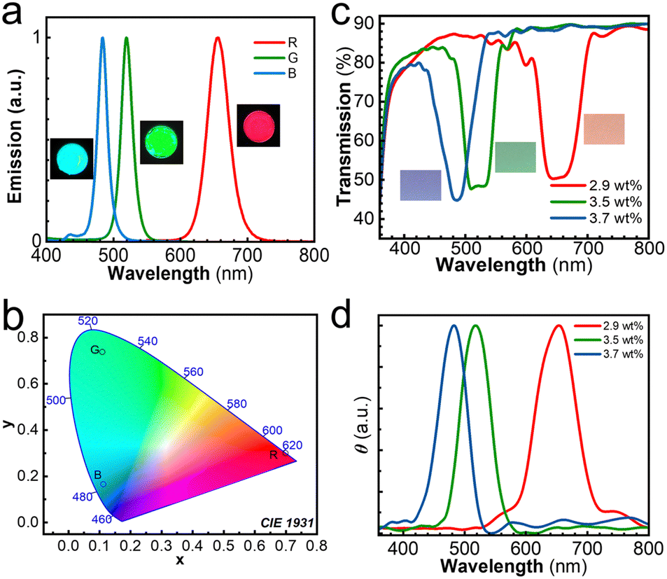 | ||
| Fig. 1 (a) Photographs and normalized emission spectra and (b) CIE 1931 spectral chromaticity of PMMA–CsPbX3 (X = Cl, Br, I) films; R: CsPbBrI2, G: CsPbBr3, B: CsPbClBr2 (λex = 355 nm); (c) photographs exposed to daylight and UV-vis, and (d) DRCD spectra of CLCN-coated PET films with different concentrations of the CA-iso. | ||
The CLC mixtures, capable of producing CLCN films with high chiral reflectivity, were selected.55 The chemical structures of LC242 and C6C1, CA-iso, and Irgacure 369 for the preparation of the CLC mixture are displayed in Fig. 2. The reactive acrylate liquid crystal monomers LC242 and C6C1 were employed to form a nematic phase. The isosorbide derivative CA-iso was used as the chiral additive to induce the cholesteric phase. The photopolymerization of liquid crystal monomers was initiated by photoinitiator Irgacure 369 under UV light exposure. By adjusting the concentration of CA-iso from 2.9 to 3.7 wt%, three CLC mixtures were prepared, and the weight ratios are listed in Table S1 (ESI†). In the polarizing optical microscopy (POM) images of the CLC mixture, a Grandjean texture was observed (Fig. S2, ESI†), indicating the formation of the cholesteric phase. These CLC mixtures were coated on the PET substrate. After photo-crosslinking reaction under UV irradiation at 80 °C, structural-coloured CLCN films with high reflectivity were produced. The preparation procedure is provided in detail in the ESI.† Their respective reflection bands were identified at 487, 520 and 651 nm (Fig. 1c). These reflection bands matched well with the emission bands of PMMA–CsPbX3 films. As the concentration of CA-iso was increased from 2.9 to 3.7 wt%, the structural colour of the CLCN-coated PET films changed from red to blue, and the reflection band was blue-shifted (Fig. 1c). The cross-sectional field emission scanning electron microscopy (FE-SEM) images displayed the supramolecular helical structure of the CLCN films (Fig. S3, ESI†). The axis of the helical structure was perpendicular to the surface of the CLCN films, with respective helical pitches of 430, 340 and 310 nm. The corresponding thicknesses were 3.05, 4.35 and 3.97 μm for the CLCN films with 2.9, 3.5 and 3.7 wt% of CA-iso. The diffuse reflectance circular dichroism (DRCD) spectra for the CLCN-coated PET films exhibited maximum signal at almost the same position as the center of the UV-vis reflection bands (Fig. 1d). Since the CA-iso was a right-handed chiral additive, right-handed helical structures were successfully induced and positive DRCD signals were identified, which further confirmed the chiral supramolecular arrangements in the polymer network films.
 | ||
| Fig. 2 Chemical structures of the compounds. | ||
Three fluorescent layers were stacked with three CLCN films separately. Namely, nine PMMA–CsPbX3/CLCN composite films were afforded. Their CPL performance was studied, and obvious positive CPL signals were observed, indicating that these composite films all exhibited left-handed CPL (Fig. 3). The CPL measurement for the composite films was conducted using method A, as shown in Fig. 4a. The fluorescent layer was placed in front of the CLCN-coated PET film, and the PET substrate was close to the PMMA–CsPbX3 layer. According to PBG theory, right-handed CPL was selectively reflected by the right-handed CLCN film, and left-handed CPL was transmitted through the CLCN-coated PET film. For the PMMA–CsPbClBr2/CLCN composite film, when the concentration of CA-iso was 3.7 wt%, the reflection bands of the blue CLCN film overlapped well with the emission band of the fluorescent PMMA–CsPbClBr2 layer. In this case, the emission wavelength located within the PBG, and the reflectivity of CLCN was quite high. The chiral optical filtering effect of the CLCN film played an important role. A high glum value of 1.67 was obtained (Fig. 3a and b). For the CLCN film prepared using 3.5 wt% of CA-iso, the reflection band partially matched with the blue emission band of the fluorescent layer, resulting in a dramatic decrease in the glum value to 0.30. For the CLCN film prepared using 2.9 wt% of CA-iso, the reflection bands shifted far away from the emission band, and the Bragg reflection intensity of the CLCN films was quite low in the band range of emission. Thus, an even lower glum value of 0.05 was obtained.
 | ||
| Fig. 3 (a) CPL spectra and (b) glum values (λem = 484 nm) of the PMMA–CsPbClBr2/CLCN composite film at different concentrations of CA-iso. (c) CPL spectra and (d) glum values (λem = 519 nm) of the PMMA–CsPbBr3/CLCN composite film at different concentrations of CA-iso; (e) CPL spectra and (f) glum values (λem = 656 nm) of the PMMA–CsPbBrI2/CLCN composite film at different concentrations of CA-iso (λex = 355 nm). | ||
 | ||
| Fig. 4 (a)–(d) Illustration of CPL measurement methods for composite films; (e) CPL spectra, (f) glum curves, and (g) glum values at 519 nm of different composite systems consisting of PMMA–CsPbBr3 and CLCN films using different methods (λex = 355 nm). | ||
Similar results were obtained for PMMA–CsPbBr3/CLCN composite film (Fig. 3c). A large glum value up to 1.73 was achieved when the green CLCN film with 3.5 wt% of CA-iso and the green emissive PMMA–CsPbBr3 were used (Fig. 3d). When the blue CLCN film with 3.7 wt% of CA-iso was used in combination with the PMMA–CsPbBr3 layer, the reflection band and the emission band did not match well. The glum value was merely 0.27. The mismatch of the reflection of the red CLCN film (with 2.9 wt% of CA-iso) with the green emission, led to a small glum value of 0.06. For the PMMA–CsPbBrI2/CLCN composite film, a high value of 1.28 was obtained when the red CLCN film was used with the red emissive PMMA–CsPbBrI2 film (Fig. 3e and f). When the concentrations of CA-iso were 3.5 and 3.7 wt%, the reflection bands were unmatched with the red emission of PMMA–CsPbBrI2 film, and the glum values were on the order of only 10−2. According to the Bragg equation (λR = nP), it is possible to tune the reflection band by changing the helical pitches of CLCN films. Consequently, by adjusting the extent of the overlap between the reflection band and the emission band, the CPL switch was achieved and large glum values could be easily modulated.
When the CLCN film was peeled off from the PET substrate, the resulting free-standing CLCN film was used for the CPL test with method B (Fig. 4b). In this case, a glum value of 1.52 was recorded, indicating that the chiral optical filtering effect of the helical CLCN film remained functional (Fig. 4e–g). In addition, the PET substrate exhibited a minor influence on the glum values. In method C, the CLCN-coated PET film was placed in front of the fluorescent layer. The excitation UV light transmitted through the CLCN layer and irradiated the PMMA–CsPbBr3 layer (Fig. 4c). Handedness inversion was observed (Fig. 4e). The right-handed CPL was selectively reflected by the CLCN film and subsequently recorded by the instrument, yielding a negative glum value of −0.39 (Fig. 4c and e–g). Such results help to better understand the CPL performance of dye-embedded CLCN films reported previously.31,32,56 Those dyes at the top surface of the CLCN film should act as the fluorescent layer in Fig. 4c, and weaken the chiral filtering effect of the CLCN film. Consequently, the |glum| values of reported dye-embedded CLCN films were typically less than 1. In method D, another CLCN film was applied based on the composite film in method C, and a multi-layer stacked composite film was built (Fig. 4d). A glum value of 1.71 was obtained (Fig. 4e–g). Such a large value was quite close to the one obtained from method A, suggesting that the chiral optical filtering effect of the CLCN film at the side of the instrument detector played a dominant role.
To further tightly combine the fluorescent layer and the CLCN layer, PAN–CsPbBr3 nanofibers were prepared directly on the surface of the CLCN-coated PET film by electrostatic spinning.57 It should be noted that PAN–CsPbBr3 nanofibers were electrostatically spun on the side of the PET substrate to prevent damage to the liquid crystal layer during spinning and the waveguide effect of the PET substrate. The PAN–CsPbBr3 was white under daylight, and exhibited a green fluorescence under 365 nm UV light (Fig. 5a), which was similar to the PMMA–CsPbBr3 film. The FE-SEM image revealed the stacking of PAN–CsPbBr3 nanofibers (Fig. 5b). The average diameter of the fibers was about 0.88 μm. The lifetime of the CsPbBr3 powder was 5574 ns, while that of the PAN–CsPbBr3 film was 5324 ns (Fig. S4, ESI†). CPL measurement was performed for the PAN–CsPbBr3/CLCN composite system (Fig. 5c). A significant glum value up to 1.48 at λem = 519 nm was detected (Fig. 5d).
 | ||
| Fig. 5 (a) Photographs of the PAN–CsPbBr3 film exposed to daylight and 365 nm UV light; (b) FE-SEM image of electro-spun PAN–CsPbBr3 nanofibers; (c) the CPL spectrum and (d) glum value curve of the PAN–CsPbBr3/CLCN composite system (λex = 355 nm). | ||
A CLCN with a flower pattern was prepared using a photomask. The CLC mixture of LC242/C6C1/Irgacure 369/CA-iso at a weight ratio of 82.0/10.0/4.5/3.5 was coated on the PET substrate. Upon irradiation using a high-pressure Hg lamp (1.0 kW), the CLC mixture in the uncovered flower area was polymerized at 80 °C. The unpolymerized CLC mixture was washed off with acetone. Under daylight, a green flower pattern was observed (Fig. 6a). Through an absorption-type left-handed circular polarizer (LC-CP), colour saturation of the pattern was observed (Fig. 6b). Through an absorption-type right-handed circular polarizer (RH-CP), the flower pattern was difficult to be identified (Fig. 6c). Thus, the CLCN pattern can be used for decoration and anti-counterfeiting under daylight. Similar results have been observed in previous works.58–60
 | ||
| Fig. 6 Pictures of the CLCN film with a flower pattern viewed (a) directly, through (b) LH- and (c) RH-CP exposed to daylight; pictures of the composite film of PMMA–CsPbBr3 and patterned CLCN viewed (d) directly, through (e) LH- and (f) RH-CP under the 365 nm UV light; scale bar: 5.0 mm. Illustration of the CPL properties of the above composite film viewed (g) directly, through (h) LH- and (i) RH-CP. | ||
Then the patterned CLCN film was stacked with the PMMA–CsPbBr3 layer. Under 365 nm UV light, the pattern was distinctly visible when viewed either directly or through an LH-CP (Fig. 6d and e). The emission intensity of the background was higher than that of the pattern area. Since the CLC mixture in the uncured area was washed off, the emission of PMMA–CsPbBr3 including both left- and right-handed CPL transmitted thoroughly through the background area of CLCN. In the flower pattern area, due to the highly effective chiral optical filtering effect of the CLCN film, right-handed CPL light emitted from the PMMA–CsPbBr3 layer was selectively reflected by the CLCN pattern, and only left-handed CPL passed through the CLCN (Fig. 6g). Left-handed CPL was subsequently blocked by the LH-CP (Fig. 6h), leading to the emission difference in Fig. 6e. When viewed through an RH-CP, the whole film was green emissive and the pattern was invisible (Fig. 6f). In this case, the left-handed CPL was transmitted from both the flower pattern and the background (Fig. 6i). Such anti-counterfeiting phenomenon under UV light was more obvious than those reported previously.56 Thus, the PMMA–CsPbBr3/CLCN composite film was quite advantageous for CPL anti-counterfeiting under UV light.
Conclusions
Herein, emissive lead-based halide perovskites, CsPbX3 (X = Cl, Br, I), were prepared, and subsequently doped into PMMA or PAN to prepare fluorescent layers with narrowband red, green, and blue emissions. These fluorescent layers were then stacked with various CLCN films to fabricate a series of composite films. Due to the high reflectivity and chiral filtering effect of highly reflective CLCN films, high |glum| values (up to 1.73) were achieved. Moreover, the composite films could also be used for CPL anti-counterfeiting. This work not only explores CPL materials incorporating perovskites and CLCNs, but also clarifies the chiral optical filtering effect of CLCN films in modulating the CPL handedness and |glum| values, which are valuable for flexible displays and anti-counterfeiting.Data availability
The data supporting this article (including preparation of PMMA–CsPbX3 films and PAN–CsPbBr3 film; preparation of CLCN films; POM images of CLC mixtures, FE-SEM images of CLCN films; emission decay curves) have been included as part of the ESI.†Conflicts of interest
There are no conflicts to declare.Acknowledgements
This work was supported by the National Natural Science Foundation of China (52273212), Jiangsu Engineering Laboratory of Novel Functional Polymeric Materials, Jiangsu Key Laboratory of Advanced Functional Polymer Materials, Key Laboratory of Polymeric Materials Design and Synthesis for Biomedical Function, and Project of Scientific and Technologic Infrastructure of Suzhou (SZS201905).References
- B. L. Feringa and R. A. van Delden, Angew. Chem., Int. Ed., 1999, 38, 3418–3438 CrossRef PubMed.
- D. P. Glavin, A. S. Burton, J. E. Elsila, J. C. Aponte and J. P. Dworkin, Chem. Rev., 2020, 120, 4660–4689 CrossRef CAS PubMed.
- M. Liu, L. Zhang and T. Wang, Chem. Rev., 2015, 115, 7304–7397 CrossRef CAS PubMed.
- Y. H. Kim, Y. Zhai, H. Lu, X. Pan, C. Xiao, E. A. Gaulding, S. P. Harvey, J. J. Berry, Z. V. Vardeny, J. M. Luther and M. C. Beard, Science, 2021, 371, 1129–1133 CrossRef CAS PubMed.
- Y. Sang, J. Han, T. Zhao, P. Duan and M. Liu, Adv. Mater., 2020, 32, 1900110 Search PubMed.
- X. Zhan, F. F. Xu, Z. Zhou, Y. Yan, J. Yao and Y. S. Zhao, Adv. Mater., 2021, 33, 2104418 CrossRef CAS PubMed.
- L. Frédéric, A. Desmarchelier, L. Favereau and G. Pieters, Adv. Funct. Mater., 2021, 31, 2010281 CrossRef.
- F. S. Richardson and J. P. Riehl, Chem. Rev., 1977, 77, 773–792 Search PubMed.
- Z. L. Gong, X. F. Zhu, Z. H. Zhou, S. W. Zhang, D. Yang, B. Zhao, Y. P. Zhang, J. P. Deng, Y. X. Cheng, Y. X. Zheng, S. Q. Zang, H. Kuang, P. Duan, M. J. Yuan, C. F. Chen, Y. S. Zhao, Y. W. Zhong, B. Z. Tang and M. Liu, Sci. China: Chem., 2021, 64, 2060–2104 CrossRef CAS.
- D. Katsis, D. U. Kim, H. P. Chen, L. J. Rothberg and S. H. Chen, Chem. Mater., 2001, 13, 643–647 CrossRef CAS.
- H. K. Bisoyi and S. Kumar, Chem. Soc. Rev., 2011, 40, 306–319 RSC.
- H. K. Bisoyi and Q. Li, Chem. Rev., 2022, 122, 4887–4926 CrossRef CAS PubMed.
- S. S. Lee, H. J. Seo, Y. H. Kim and S. H. Kim, Adv. Mater., 2017, 29, 1606894 CrossRef PubMed.
- J. Yan, F. Ota, B. A. San Jose and K. Akagi, Adv. Funct. Mater., 2017, 27, 1604529 CrossRef.
- L. Qin, X. Liu, K. He, G. Yu, H. Yuan, M. Xu, F. Li and Y. Yu, Nat. Commun., 2021, 12, 699 CrossRef CAS PubMed.
- Y. Shi, J. Han, C. Li, T. Zhao, X. Jin and P. Duan, Nat. Commun., 2023, 14, 6123 CrossRef CAS PubMed.
- Y. Wu, M. Li, Z. Zheng, Z.-Q. Yu and W.-H. Zhu, J. Am. Chem. Soc., 2023, 145, 12951–12966 CrossRef CAS PubMed.
- H. K. Bisoyi and Q. Li, Acc. Chem. Res., 2014, 47, 3184–3195 CrossRef CAS PubMed.
- E. Yablonovitch, Phys. Rev. Lett., 1987, 58, 2059–2062 CrossRef CAS PubMed.
- A. Bobrovsky, V. Shibaev and J. Stumpe, J. Phys. Chem. A, 2006, 110, 2331–2336 CrossRef CAS PubMed.
- S. H. Chen, D. Katsis, A. W. Schmid, J. C. Mastrangelo, T. Tsutsui and T. N. Blanton, Nature, 1999, 397, 506–508 CrossRef CAS.
- Z. Li, R. Lan, J. Bao, W. Hu, M. Wang, L. Zhang and H. Yang, ACS Appl. Mater. Interfaces, 2022, 14, 8490–8498 Search PubMed.
- Y. Li, Y. Chen, J. Luo, Y. Quan and Y. Cheng, Adv. Mater., 2024, 36, 2312331 Search PubMed.
- H. Zhong, X. Gao, B. Zhao and J. Deng, Acc. Chem. Res., 2024, 57, 1188–1201 CrossRef CAS PubMed.
- X. Yang, X. Jin, T. Zhao and P. Duan, Mater. Chem. Front., 2021, 5, 4821–4832 Search PubMed.
- X. Lu, Z. Zhou, B. Ni, H. Li, Y. Li, B. Li, W. Liu, Y. Wang and Y. Yang, J. Mater. Chem. C, 2022, 10, 8246–8253 Search PubMed.
- M. Portugall, H. Ringsdorf and R. Zentel, Makromol. Chem., 2003, 183, 2311–2321 CrossRef.
- N. Herzer, H. Guneysu, D. J. Davies, D. Yildirim, A. R. Vaccaro, D. J. Broer, C. W. M. Bastiaansen and A. P. H. J. Schenning, J. Am. Chem. Soc., 2012, 134, 7608–7611 Search PubMed.
- T. J. White and D. J. Broer, Nat. Mater., 2015, 14, 1087–1098 Search PubMed.
- B. Ni, Y. Li, W. Liu, B. Li, H. Li and Y. Yang, Chem. Commun., 2021, 57, 2796–2799 RSC.
- T. Lian, R. Yu, W. Liu, Y. Li and Y. Yang, J. Mater. Chem. C, 2023, 11, 10993–11000 Search PubMed.
- N. Yang, J. Zhao, W. Liu, Y. Li and Y. Yang, Adv. Opt. Mater., 2025, 13, 2402128 CrossRef CAS.
- C. Ji, L. Lai, P. Li, Z. Wu, W. Cheng and M. Yin, Aggregate, 2021, 2, e39 CrossRef CAS.
- R. Banasz and M. Wałęsa-Chorab, Coord. Chem. Rev., 2019, 389, 1–18 Search PubMed.
- J. C. Bunzli and C. Piguet, Chem. Soc. Rev., 2005, 34, 1048–1077 RSC.
- W. P. Lustig, S. Mukherjee, N. D. Rudd, A. V. Desai, J. Li and S. K. Ghosh, Chem. Soc. Rev., 2017, 46, 3242–3285 RSC.
- J. Liu, T. Kong and H. M. Xiong, Adv. Mater., 2022, 34, 2200152 CrossRef CAS PubMed.
- X. Michalet, F. F. Pinaud, L. A. Bentolila, J. M. Tsay, S. Doose, J. J. Li, G. Sundaresan, A. M. Wu, S. S. Gambhir and S. Weiss, Science, 2005, 307, 538–544 CrossRef CAS PubMed.
- Y. Hong, J. W. Lam and B. Z. Tang, Chem. Commun., 2009, 4332–4353 RSC.
- H. Zhang, Z. Zhao, P. R. McGonigal, R. Ye, S. Liu, J. W. Y. Lam, R. T. K. Kwok, W. Z. Yuan, J. Xie, A. L. Rogach and B. Z. Tang, Mater. Today, 2020, 32, 275–292 CrossRef CAS.
- T. Duan and Y. Zhou, Adv. Energy Mater., 2022, 13, 2200792 CrossRef.
- D. Wu, H. Zhang, Z. Wang, Y. Zhang, G. Zhang, K. Wang and C. Z. Ning, Adv. Opt. Mater., 2024, 12, 2401131 CrossRef CAS.
- Y. Shen, T. Zhang, G. Xu, J. A. Steele, X. Chen, W. Chen, G. Zheng, J. Li, B. Guo, H. Yang, Y. Wu, X. Lin, T. Alshahrani, W. Yin, J. Zhu, F. Wang, A. Amassian, X. Gao, X. Zhang, F. Gao, Y. Li and Y. Li, Nature, 2024, 635, 882–889 CrossRef CAS PubMed.
- Y. Wang, R. Lin, C. Liu, X. Wang, C. Chosy, Y. Haruta, A. D. Bui, M. Li, H. Sun, X. Zheng, H. Luo, P. Wu, H. Gao, W. Sun, Y. Nie, H. Zhu, K. Zhou, H. T. Nguyen, X. Luo, L. Li, C. Xiao, M. I. Saidaminov, S. D. Stranks, L. Zhang and H. Tan, Nature, 2024, 635, 867–873 CrossRef PubMed.
- X. Qian, Y. Shen, L. J. Zhang, M. Guo, X. Y. Cai, Y. Lu, H. Liu, Y. F. Zhang, Y. Tang, L. Chen, Y. Tang, J. Wang, W. Zhou, X. Gao, H. Mao, Y. Li, J. X. Tang and S. T. Lee, ACS Nano, 2022, 16, 17973–17981 CrossRef CAS PubMed.
- M. Zhao, Q. Zhang and Z. Xia, Mater. Today, 2020, 40, 246–265 CrossRef CAS.
- B. Zhao, X. Gao, K. Pan and J. Deng, ACS Nano, 2021, 15, 7463–7471 CrossRef CAS PubMed.
- W. Chen, S. Zhang, M. Zhou, T. Zhao, X. Qin, X. Liu, M. Liu and P. Duan, J. Phys. Chem. Lett., 2019, 10, 3290–3295 CrossRef CAS PubMed.
- Z.-B. Liang, X. Chen, X.-J. Liao, J.-J. Li, Y. Yang, C.-F. Wang, Y.-X. Zheng and S. Chen, J. Mater. Chem. C, 2022, 10, 12644–12651 RSC.
- X. Zhang, L. Li, Y. Chen, C. Valenzuela, Y. Liu, Y. Yang, Y. Feng, L. Wang and W. Feng, Angew. Chem., Int. Ed., 2024, 63, e202404202 Search PubMed.
- S. Liu, X. Liu, Y. Wu, D. Zhang, Y. Wu, H. Tian, Z. Zheng and W.-H. Zhu, Matter, 2022, 5, 2319–2333 Search PubMed.
- Y. Wang, J. He, H. Chen, J. Chen, R. Zhu, P. Ma, A. Towers, Y. Lin, A. J. Gesquiere, S. T. Wu and Y. Dong, Adv. Mater., 2016, 28, 10710–10717 Search PubMed.
- P. Lin, Q. Yan, Z. Wei, Y. Chen, F. Chen, Z. Huang, X. Li, H. Wang, X. Wang and Z. Cheng, Opt. Express, 2018, 26, 18310 Search PubMed.
- X. Li, Y. Wu, S. Zhang, B. Cai, Y. Gu, J. Song and H. Zeng, Adv. Funct. Mater., 2016, 26, 2435–2445 CrossRef CAS.
- Z. Li, J. Zhao, L. Wu, Y. Li, W. Liu and Y. Yang, Liq. Cryst., 2024, 51, 432–441 CrossRef CAS.
- L. Xu, F. Shi, J. Zhao, L. Wu, H. Li, Y. Li, W. Liu and Y. Yang, ACS Appl. Mater. Interfaces, 2024, 16, 15242–15250 CrossRef CAS PubMed.
- X. Fang, C. Liu, H. Peng, Y. Li and Y. Yang, Mater. Lett., 2024, 354, 135391 CrossRef CAS.
- J. Zhao, M. Zhang, Y. Guo, W. Liu, Y. Li and Y. Yang, Giant, 2024, 17, 100244 Search PubMed.
- J. Zhao, R. Yu, L. Wu, Y. Li, W. Liu and Y. Yang, Chem. – Asian J., 2023, 18, e202300636 CrossRef CAS PubMed.
- S. Li, Y. Tang, Q. Fan, Z. Li, X. Zhang, J. Wang, J. Guo and Q. Li, Light: Sci. Appl., 2024, 13, 140 CrossRef CAS PubMed.
Footnote |
| † Electronic supplementary information (ESI) available: Preparation of PMMA–CsPbX3 films and PAN–CsPbBr3 film; preparation of CLCN films; POM images of CLC mixtures, FE-SEM images of CLCN films; emission decay curves. See DOI: https://doi.org/10.1039/d4tc05268d |
| This journal is © The Royal Society of Chemistry 2025 |