
 Open Access Article
 This Open Access Article is licensed under a
 Creative Commons Attribution 3.0 Unported Licence
Structural frustration effects by mixed alkali ions in ferroelectric Dion–Jacobson layered perovskites (Cs,Rb)NdNb2O7†
Zhen-Tao
Lu
 a,
Sota
Asaki
a,
Suguru
Yoshida
b,
Chikako
Moriyoshi
c,
George
Hasegawa
e,
Koji
Fujita
d,
Venkatraman
Gopalan
b,
Katsuro
Hayashi
a and
Hirofumi
Akamatsu
*a
a,
Sota
Asaki
a,
Suguru
Yoshida
b,
Chikako
Moriyoshi
c,
George
Hasegawa
e,
Koji
Fujita
d,
Venkatraman
Gopalan
b,
Katsuro
Hayashi
a and
Hirofumi
Akamatsu
*a
aDepartment of Applied Chemistry, Kyushu University, Motooka, Fukuoka 819-0395, Japan. E-mail: h.akamatsu@cstf.kyushu-u.ac.jp
bMaterials Research Institute and Department of Materials Science, Pennsylvania State University, University Park, Pennsylvania 16802, USA
cGraduate School of Advanced Science and Engineering, Hiroshima University, Higashihiroshima, Hiroshima 739-8526, Japan
dDepartment of Material Chemistry, Kyoto University, Nishikyo, Kyoto 615-8510, Japan
eInstitute of Materials and Systems for Sustainability, Nagoya University, Nagoya 464-8601, Japan
First published on 25th November 2024
Abstract
Two Dion–Jacobson (DJ) double-layered perovskites CsNdNb2O7 and RbNdNb2O7 exhibit hybrid improper ferroelectricity, in which spontaneous polarization is induced by coupling of two types of nonpolar oxygen octahedral rotations (OORs). Their crystal structures adopt common polar distortion modes, although they exhibit distinct OOR patterns. In this study, complete solid-solution Cs1−xRbxNdNb2O7 ceramics (x = 0, 0.25, 0.5, 0.75, and 1) have been synthesized by conventional solid-state reaction methods, and the temperature-composition phase diagram has been established by various methods including variable-temperature synchrotron X-ray diffractometry, differential scanning calorimetry, optical second harmonic generation, and dielectric permittivity measurements. The powder X-ray diffractometry reveals that Cs-rich compounds (x ≤ 0.25) crystalize into polar P21am structures with a−a−c+/a−a−c+ OORs at room temperature, while Rb-rich compounds (x ≥ 0.5) adopt polar I2cm structures with a−a−c+/−(a−a−c+) OORs. All the solid solutions exhibit ferroelectricity at room temperature. Upon heating, successive phase transitions involving the loss of polar distortions and OORs have been observed. The phase transition temperatures of the solid solutions with intermediate compositions are lower than those predicted based on Vegard's law, indicating structural frustration effects due to the random arrangement of two alkali metal ions. This work provides insight into the influence of alkali metal ions in the intervening layers on the structural and ferroelectric properties of DJ layered perovskites.
Introduction
Noncentrosymmetric materials have distinctive functional properties such as second-order nonlinear optical effects,1,2 ferroelectricity,3,4 pyroelectricity,5,6 and piezoelectricity.7,8 Ferroelectric materials have garnered significant interest for their fundamental physics due to their switchable spontaneous polarization under external fields.9–11 They can be widely applied in non-volatile memory,12 solar cells,13 photocatalysts,14 and solid-state refrigeration.15 However, widely used commercial ferroelectric materials such as Pb(Zr,Ti)O316,17 and (Pb,La)(Zr,Ti)O318,19 include highly toxic lead, which damages human health and pollutes the environment. Thus, urgent efforts are needed to develop novel lead-free ferroelectric materials to replace current commercial lead-containing materials, ensuring the advancement of various applications while mitigating environmental and health concerns.Simple perovskite oxides have a chemical formula of ABO3, where the A-site cations are usually large cations such as alkali, alkaline earth, and rare earth cations as well as Pb2+ and Bi3+, while the octahedrally coordinated B sites are typically occupied by small cations including transition metal ions. Most perovskite oxides crystallize in centrosymmetric structures, which conflict with the requirements for ferroelectric materials. Noncentrosymmetric perovskites account just for ∼0.4% of all perovskites in the Inorganic Crystal Structure Database (ICSD), indicating a great challenge to find novel ferroelectric perovskites.20 However, the discovery of hybrid improper ferroelectricity (HIF) has opened up new avenues for designing polar perovskite-related compounds.21,22 In HIF, spontaneous polarization is induced by a trilinear coupling term between a polar distortion mode and other two nonpolar oxygen octahedral rotation (OOR) modes in free energy.21–25
HIF is commonly found in the layered perovskites without inversion symmetry around the B sites. Ferroelectric properties have been reported for many Ruddlesden–Popper (RP) layered perovskite oxides with a chemical formula of A′2(An−1BnO3n+1) such as Ca3Ti2O726 and Sr3M2O7 (M = Zr, Hf, Sn),27–30 which exhibit OORs represented by a−a−c+-type in Glazer notation31 below Curie temperature, TC. Yoshida et al.4 have reported for the RP ferroelectrics that TC linearly increases with a lowering Goldschmidt tolerance factor, τ, defined as follows:32,33
 | (1) |
 | ||
| Fig. 1 Schematic crystal structures for (a) aristotype Ruddlesden–Popper and (b) Dion–Jacobson-type double-layered perovskites. Room-temperature crystal structures of (c) CsNdNb2O7 (space group: P21am) and (d) RbNdNb2O7 (space group: I2cm). The black solid boxes indicate unit cells. The green dash boxes in (a) and (b) highlight the local environments around the oxygen octahedra. The orange-colored NbO6 octahedra in (c) and (d) indicate the octahedra with the same sense of octahedral rotations. | ||
HIF has been also demonstrated for Dion–Jacobson (DJ) layered perovskite niobates and tantalates with a general chemical formula of A′(An−1BnO3n+1). As summarized in Table 1 and shown in Fig. S1 (ESI†), however, the number of reports of HIF DJ phases34–40 is still limited thus far compared to HIF RP phases. In DJ oxides, A-site and A′-site cations are placed in the perovskite slabs and the intervening layers with CsCl structures, respectively (Fig. 1b). Unlike RP structures, the BO6 octahedra in DJ phases have significantly different surrounding environments compared to simple perovskites; the A′-site cations are distanced from the octahedra, disrupting the perovskite geometry. Therefore, the influence of A-site and A′-site cations on the structural properties including OOR instability is different from each other.
| Compound | Space group | Glazer notation | T C (K) | Ref. |
|---|---|---|---|---|
| a This compound undergoes a polar-to-polar phase transition at 537 K, below which the number of OOR axes is increased from two to three. In this study, this temperature is regarded as TC of RbPrNb2O7 because we focus on the OOR instability. b These have intervening layers other than CsCl-type structures. | ||||
| RbPrNb2O7 | I2cm | a − a − c +/−(a−a−c+) | 537a | 38 |
| CsSmNb2O7 | P21am | a − a − c + | 1113 | 37 |
| RbSmNb2O7 | I2cm | a − a − c +/−(a−a−c+) | — | 37 |
| CsNdNb2O7 | P21am | a − a − c + | 625 | 35 |
| CsNdTa2O7 | P21am | a − a − c + | 330 | 35 |
| RbNdNb2O7 | I2cm | a − a − c +/−(a−a−c+) | 790 | 35 |
| RbNdTa2O7 | I2cm | a − a − c +/−(a−a−c+) | 500 | 35 |
| CsLaNb2O7 | Amm2 | a − b 0 c + | 325 | 39 |
| CsBiNb2O7 | P21am | a − a − c + | 1306 | 36 |
| RbBiNb2O7 | P21am | a − a − c + | 1371 | 36 |
| RbBiNb2O7 | P21am | a − a − c + | 1218 | 40 |
| LiNdNb2O7b | B2cm | a − a − c +/−(a−a−c+) | — | 34 |
| KNdNb2O7b | Im2m | a 0 b + c 0/a0−b+c0 | — | 34 |
| KNdTa2O7b | Im2m | a 0 b + c 0/a0−b+c0 | — | 34 |
To extract the effect of the A-site cations on OOR instability, it is beneficial to focus on the DJ phases with identical A′-site and B-site ions but distinct A-site ions. CsSmNb2O7 has a higher TC of 1363 K than CsNdNb2O7 with TC = 625 K. This is attributed to the smaller ionic radius of Sm3+ compared to Nd3+, which results in a smaller value of τ. Moreover, RbNdNb2O7 (790 K)35 has higher TC than RbPrNb2O7 (537 K),38 which is ascribed to the smaller ionic radius of Nd3+ compared to Pr3+. Thus, the dependence of OOR instability on the ionic radius of A-site ions is explained based on τ. It should be noted that Bi-based DJ oxides RbBiNb2O7 and CsBiNb2O7 show much higher TC's than other DJ oxides, deviating from the trends described above. This is because the stereochemically active lone pair 6s electrons in Bi3+ ions enhance the ferroelectric instability.
The A′-site ions have more complex effects on the crystal structures including the stacking arrangements of perovskite slabs as well as the OOR patterns and instability. DJ phases are stabilized for A′ = Cs and Rb, whereas the stacking arrangements become different when A′ ions are small alkali ions such as K+, Na+, and Li+, as these ions prefer to lower coordination numbers, disrupting the formation of intervening CsCl-type layers.34 CsANb2O7 and RbANb2O7 (A = Pr, Nd, and Sm) crystallize in polar P21am and I2cm structures, adopting different OOR patterns with a−a−c+- and a−a−c+/−(a−a−c+)-types, respectively, as shown in Fig. 1c and d.41 (Here, the OOR patterns of the adjacent slabs are written before and behind a slash, and the opposite sense of rotation and tilting is denoted by a prefactor of minus sign.) Rb-based DJ compounds typically exhibit higher TC values than Cs counterparts for rare-earth DJ phases35 (see Fig. S1, ESI†). It cannot be hastily concluded that this is due to the smaller ionic radius of Rb+ ions than that of Cs+ ions, because they show similar but distinct OOR patterns. Comprehensive understanding of the effects of the A′-site cations on the OOR instability requires systematic variation of the A′-site cations. The structural and dielectric properties have not yet been examined for solid solutions of DJ phases with different OOR patterns thus far.
In this work, we have systematically investigated the relationship between structural and ferroelectric properties of complete solid-solution Cs1−xRbxNdNb2O7 ceramics (x = 0, 0.25, 0.5, 0.75, and 1) with varying Rb/Cs ratio at the A′ sites. This system is a rare example of the complete solid solutions with end members exhibiting HIF. To the best of our knowledge, such a complete solid solution has only been reported for Sr3(Sn,Zr)2O7.42 Ferroelectricity was observed for all the samples at both 77 K and room temperature. Variable-temperature synchrotron X-ray diffraction (SXRD) reveals structural phase transitions on cooling from aristotype P4/mmm via intermediate phases to polar P21am and I2cm phases for Cs- and Rb-rich compounds, respectively. Their polar-to-nonpolar phase transitions are also tracked by various characterizations including differential scanning calorimetry (DSC), optical second harmonic generation (SHG) measurements, and dielectric permittivity measurements. Noticeably, phase transition temperatures deviate from those predicted based on the Vegard's law. This likely stems from structural frustration effects owing to the disordered arrangement of two types of A′-site alkali metal ions, which determine the sense of OORs between the adjacent slabs.
Experimental
Sample synthesis
Conventional solid-state reaction methods were used to synthesize a series of DJ perovskites Cs1−xRbxNdNb2O7 (x = 0, 0.25, 0.5, 0.75, and 1). The reagent-grade powders of Cs2CO3 (99.9%; Kojundo Chemical Laboratory Co. Ltd), Rb2CO3 (99.9%; Kojundo Chemical Laboratory Co. Ltd), Nd2O3 (99.9%; Kojundo Chemical Laboratory Co. Ltd), and Nb2O5 (99.9%; Sigma-Aldrich Co. Ltd) were chosen as raw materials. The raw materials were weighted to ensure a 20% excess of alkali metal elements relative to the stoichiometric compositions, followed by thorough mixing using an agate mortar. Following grinding with ethanol for 15 min, the mixtures were transferred to an 80 °C oven for drying before being compacted into 20 mm diameter pellets at 40 MPa. These pellets were then placed on Pt sheets in alumina crucibles, subject to calcination at 850 °C for 24 h, and subsequently ground into powders. A double-step pressing process was performed; the ground powders were initially pelletized at 40 MPa using a uniaxial pressing, followed by pressing the pellets to a hydrostatic 200 MPa pressure for 15 min. The resultant pellets were sintered at 1000 °C for 48 hours, yielding dense pellets displaying a light violet coloration due to the 4f–4f transition in Nd ions. The relative densities of sintered pellets were ca. 95% for all the compositions.Surface morphology characterization and chemical element analysis
The scanning electron microscopy (SEM) equipped with energy dispersive X-ray spectroscopy (EDS) was used to observe the microstructures and measure chemical compositions of Cs1−xRbxNdNb2O7 (x = 0, 0.25, 0.5, 0.75, and 1) ceramics, respectively, with a JCM-7000 instrument (JEOL Ltd.). The applied voltage was set as 15.0 keV.SXRD
Variable-temperature synchrotron SXRD patterns were measured with MYTHEN solid-state detectors installed at SPring-8 BL02B2 beamline equipping a Debye–Scherrer camera via two types of measurement modes referred to as single- and double-step modes described in ref. 43 in detail. In the single-step modes, XRD patterns were recorded for an exposure time of 14 s by sweeping temperature from 1100 to 300 K at a rate of 20 K min−1, resulting in a temperature resolution of ca. 5 K. In the double-step mode, XRD patterns were collected at various temperatures for an exposure time of 180 s by increasing temperature from 300 to 1100 K with intervals of 50 or 100 K in a stepwise way to obtain diffraction data suitable for Rietveld refinements. Silica or Lindemann glass capillary tubes with 0.1 mm diameter were used to load ground powder samples. To reduce the negative effects of the preferred orientation, the capillary tubes were always rotated during measurements. The monochromated X-ray beam has λ = 0.67049 or 0.669077 Å to avoid Nb K-edge absorption (0.6532 Å) and detect the lowest angle peaks within 2θ range of the beamline (≥2°). The FullProf Suite was used to perform Rietveld refinements against SXRD patterns recorded using the double-step measurement mode.44 The VESTA code45 was employed to visualize crystal structures and calculate bond valence sums (BVSs) with the bond valence parameters reported in ref. 46 to verify the validity of the refined structure.Raman spectra measurement
A micro-Raman spectrometer equipped with a 532 nm semiconductor laser (XploRA, HORIBA, Ltd) was used to record the Raman spectra of samples from 50 to 1050 cm−1.DSC
DSC was measured using Rigaku Thermo plus DSC8270. The data from RT to 1273 K were collected at a heating and cooling rate of 10 K min−1.Temperature-dependent SHG measurement
Optical SHG signals were measured in reflection geometry with an 800-nm fundamental beam (Ti:sapphire laser, 80 fs pulses, 1 kHz repetition rate). Temperature control was achieved using a home-built heater.Temperature-dependent permittivity measurement
For the temperature-dependent permittivity measurement, the sintered pellets were shaped to thin discs with a thickness of 0.3–0.5 mm followed by putting Pt films on both sides by sputtering. An LCR meter (IM3536, HIOKI Co. Ltd.) connected to a cryostat (TERADA Co. Ltd.) and a temperature controlling stage (Linkam Scientific Instruments Ltd, 19624L) were used to measure capacitances and dielectric losses in low- (5–300 K) and high-temperature (300–873 K) regions, respectively.Electric polarization-field curve measurement
Electric polarization-field (P–E) curves for all the compositions were measured with a Radiant Precision LCII ferroelectric tester and a Trek 609B voltage amplifier at 77 K and RT to characterize the ferroelectric properties. The samples were polished so that they had a thickness of 0.1–0.2 mm. The sample pellets with Pt electrodes were put into liquid nitrogen to record low-temperature data. For RT measurements, the pellet samples were immersed in silicon oil to avoid the electric leakage in air. Gold film electrodes were deposited on the pellets because they were not dispersed into silicon oil. Remanent hysteresis measurement methods implemented in the ferroelectric tester were employed to exclude the effects of leaky current and linear response. The maximum amplitude of electric field was 100 kV cm−1. The P–E curves were obtained from three pellet samples for each composition to consider statistical errors and thereby guarantee the data reliability.Results
Room-temperature structures of Cs1−xRbxNdNb2O7
The room-temperature phases of Cs1−xRbxNdNb2O7 are identified in this section. Fig. 2a shows the room-temperature SXRD patterns of Cs1−xRbxNdNb2O7. The SXRD patterns of CsNdNb2O7 and RbNdNb2O7 are in good agreement with those reported previously.35,47 Zhu et al. studied the crystal structures for the end members by a combination of X-ray and neutron diffractions in detail.35 CsNdNb2O7 and RbNdNb2O7 crystalize in the polar structures with P21am (Fig. 1c) and I2cm (Fig. 1d) space group symmetry, the OOR patterns of which are denoted by a−a−c+/a−a−c+ and a−a−c+/−(a−a−c+), respectively. In CsNdNb2O7, the adjacent AB2O7 double perovskite slabs with a−a−c+-type OORs are stacked in a primitive manner. Meanwhile, each perovskite slab of RbNdNb2O7 shows a−a−c+-type OORs with the sense of OORs being opposite to that in the adjacent slabs, as depicted in Fig. 1d. This results in a body-centered I-lattice, making the conventional unit cell doubled compared to that of CsNdNb2O7. The OOR modes for the P21am and I2cm structures transform like the direct sums of irreducible representations (irreps) of P4/mmm, M2+ ⊕ M5− and A2+ ⊕ A5−, respectively. These direct sums induce common polar distortion modes transforming like irrep Γ5−. Zhu et al. suggested that the distinct stacking of adjacent layers is attributed to the bonding preference of A- and A′-site cations and the minimization of O–O repulsion.35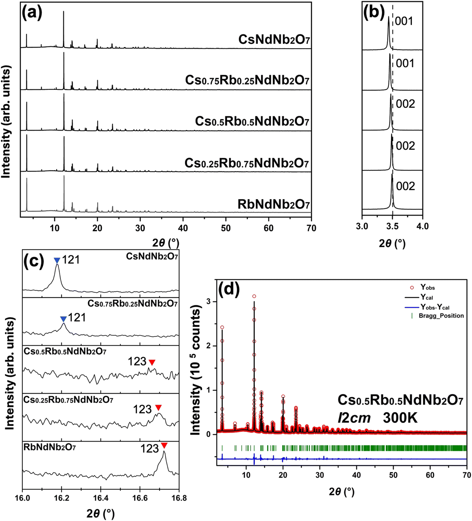 | ||
| Fig. 2 Phase identification for Cs1−xRbxNdNb2O7 (x = 0, 0.25, 0.5, 0.75, and 1) at room temperature. Panel (a) depicts the whole SXRD patterns. Panel (b) highlights the lowest-angle 001 or 002 diffraction peaks for the P21am and I2cm phases, respectively. Panel (c) shows the selected diffraction peaks that distinguish the P21am and I2cm phases. (d) Rietveld refinement result for the room-temperature SXRD pattern of Rb0.5Rb0.5NdNb2O7 with an I2cm structural model. | ||
The overall features of SXRD patterns are common to the Cs1−xRbxNdNb2O7 solid solutions, indicating that DJ structures are maintained in the whole compositional range. This is also corroborated by the similar Raman spectra of the solid solutions (see Fig. S2, ESI†). The EDS analysis reveals that the A′-site Rb/Cs ratio is comparable to nominal Rb/Cs ratio as shown in Fig. S3 (ESI†). These results suggest that the CsNdNb2O7–RbNdNb2O7 system shows complete miscibility, even when the ionic radius of Cs+ is 15% larger than that of Rb+. The lowest-angle diffraction peaks relevant to the out-of-plane lattice constants monotonously shift to the higher-angle side with increasing Rb contents, as shown in Fig. 2b, indicating that larger Cs ions are successfully replaced with smaller Rb ions. This is likely because of the structural flexibility of the intervening layers accommodating the A′-site cations.
The distinct features of the SXRD patterns that distinguish the P21am and I2cm structures are required to find the compositional phase boundary. The reflection conditions for P21am are h00 and h0l: h = 2n with n being integer, while those for I2cm are hkl: h + k + l = 2n and h0l: l = 2n. According to the reflection rules, the space group symmetry of Cs-rich compositions, Cs1−xRbxNdNb2O7 with x = 0 and 0.25, is identified as P21am, while that of Rb-rich compositions, x = 0.5, 0.75 and 1, is determined to be I2cm. Fig. 2c displays the selected angle region including 121 and 123 diffraction peaks for the P21am and I2cm structures, respectively, as typical features distinguishing the two phases. The P21am phases exhibit 121 diffraction peaks around 2θ = 16.2°, whereas the I2cm phases show no peaks in this region. Meanwhile, the I2cm phases exhibit 123 diffraction peaks around 2θ = 16.7°, whereas the P21am phases show no peaks in this angle range. The I2cm phases undergo cell doubling along the c axis with respect to the P21am phase. Therefore, the 121 diffraction peak for the P21am phases corresponds to the 122 diffraction peak for the I2cm phase, which is prohibited for the body-centered lattice; h + k + l is odd. Meanwhile, the 123 diffraction for the I2cm phase corresponds to the half-integer 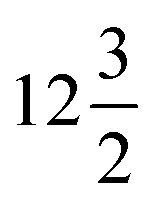 diffraction for the P21am phase, resulting in the absence of the peaks. Thus, the two phases can be readily distinguished by examining the 121 diffraction for the P21am phases and the 123 diffraction for the I2cm phases. Fig. 2d presents profile fitting of the SXRD pattern for Cs0.5Rb0.5NdNb2O7 with a I2cm structural model as a representative Rietveld refinement result. Acceptable fitting was obtained for all the room-temperature SXRD patterns with the structural models identified above. The close inspection of the XRD patterns revealed that all the samples contain negligible secondary phases, verifying the good quality of the samples.
Phase transition pathways of Cs1−xRbxNdNb2O7
To construct a temperature-composition phase diagram in the Cs1−xRbxNdNb2O7 system, variable-temperature SXRD measurements were conducted with a fine temperature resolution of ca. 5 K using the single-step measurement mode. The wavelength used in the measurements for CsNdNb2O7 and RbNdNb2O7 is 0.669077 Å, while that for Cs0.75Rb0.25Nb2O7, Cs0.5Rb0.5Nb2O7 and Cs0.25Rb0.75Nb2O7 is 0.670489 Å. Fig. 3 shows the selected angle region of temperature-dependent SXRD patterns for Cs1−xRbxNdNb2O7. The phase transition behavior of the end members CsNdNb2O7 and RbNdNb2O7 is almost consistent with that reported by Zhu et al., albeit with a minor discrepancy.35 CsNdNb2O7 goes through a polar-to-nonpolar phase transition from the P21am phase with a−a−c+-type OORs to a monoclinic C2/m phase with a−b0c−-type OORs at 630 K, and then transforms to the aristotype P4/mmm phase at 790 K on heating (see Fig. 3a), in good agreement with the report by Zhu et al.35 Meanwhile, upon heating, RbNdNb2O7 undergoes a polar-to-nonpolar phase transition from the I2cm phase with a−a−c+/−(a−a−c+)-type OORs to a Cmca phase with a−b0c−/−(a−b0)c−-type OORs at 740 K, and then transforms to an undistorted P4/mmm phase at 880 K (see Fig. 3e). The previous neutron powder diffraction study revealed a phase transition from the Cmca phase to an I4/mcm phase with a0a0c−/a0a0−c−-type OORs at 865 K on heating.35 This was not detected by our SXRD likely due to the poor sensitivity of X-ray to the positions of light atoms. The I4/mcm phase exhibits the OORs, whereas the P4/mmm phase does not; the difference between the I4/mcm and P4/mmm phases lies not in the cation's positions but in the oxygen's positions. The resultant superlattice reflections of the I4/mcm phase are too weak to be detected by X-ray. In both the end members, the number of OOR axes increases as the phase transitions occur upon cooling, indicating that the phase transitions are mainly driven by the OOR instability. The phase transition behavior of the solid solutions is categorized into two distinct groups; the Cs-rich Cs0.75Rb0.25NdNb2O7 sample follows the same phase transition pathway as CsNdNb2O7 (P21am–C2/m–P4/mmm) (see Fig. 3b), while the Rb-rich Cs0.5Rb0.5NdNb2O7 and Cs0.25Rb0.75NdNb2O7 samples follow the same phase transition pathway as RbNdNb2O7 (I2cm–Cmca–(I4/mcm–)P4/mmm) (see Fig. 3c and d). | ||
| Fig. 3 Two-dimensional plots of the temperature-dependent SXRD patterns around 2θ = 20° for Cs1−xRbxNdNb2O7 with x = (a) 0, (b) 0.25, (c) 0.5, (d) 0.75, and (e) 1. | ||
Let us see the variation of diffraction patterns with temperature in detail. Fig. 3a and b depict the variable-temperature SXRD patterns around 2θ = 20° for the Cs-rich CsNdNb2O7 and Cs0.75Rb0.25NdNb2O7 samples, respectively. Upon heating, a single 220 diffraction peak of the polar P21am phase splits into 400 and 040 diffraction peaks of the nonpolar C2/m phase. Meanwhile, 204 and 024 diffraction peaks of P21am phase are converted to 224 and 22![[4 with combining macron]](https://www.rsc.org/images/entities/char_0034_0304.gif) diffraction peaks of the C2/m phase. These observations reflect the unit-cell doubling from an orthorhombic
diffraction peaks of the C2/m phase. These observations reflect the unit-cell doubling from an orthorhombic 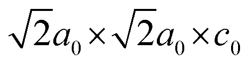 cell to a monoclinic 2a0 × 2a0 × 2c0 cell, where a0 and c0 are the lattice constants of the aristotype P4/mmm phase. As shown in Fig. S4a and b (ESI†), this phase transition is also reflected by 200 and 020 diffraction peaks of the P21am phase around 2θ = 14° merging into a single 220 peak of the C2/m phase. The P21am-to-C2/m phase transition is a ferroelectric-to-paraelectric phase transition, as confirmed by optical SHG, permittivity, and P–E curve measurements below. The Curie temperatures (TC) are 630 and 640 K for CsNdNb2O7 and Cs0.75Rb0.25NdNb2O7, respectively. Another phase transition was observed at higher temperatures from 400 and 040 diffraction peaks of the nonpolar C2/m phase merging into a single 200 diffraction peak of the P4/mmm phase due to the unit-cell reduction from 2a0 × 2a0 × c0 for the C2/m phase to a0 × a0 × c0 for the P4/mmm phase. This phase transition is also reflected by
 ![[2 with combining macron]](https://www.rsc.org/images/entities/char_0032_0304.gif) 24 and 224 diffraction peaks of the C2/m phase around 2θ = 20° merging into a single 114 diffraction peak of the P4/mmm phase [see also Fig. S4c and d, ESI†]. The C2/m-to-P4/mmm phase transition temperatures are 790 and 770 K for CsNdNb2O7 and Cs0.75Rb0.25NdNb2O7, respectively.
24 and 224 diffraction peaks of the C2/m phase around 2θ = 20° merging into a single 114 diffraction peak of the P4/mmm phase [see also Fig. S4c and d, ESI†]. The C2/m-to-P4/mmm phase transition temperatures are 790 and 770 K for CsNdNb2O7 and Cs0.75Rb0.25NdNb2O7, respectively.
Fig. 3c–e depict the variable-temperature SXRD patterns around 2θ = 20° for the Rb-rich samples. Upon heating, a single 220 diffraction peak of the polar I2cm phase splits into 400 and 040 diffraction peaks of the nonpolar Cmca phases due to the unit-cell doubling from  for I2cm to 2a0 × 2a0 × c0 for Cmca [see also Fig. S5a–c, ESI†]. These phase transitions are ferroelectric–paraelectric transitions. The TC values are 620, 690, and 740 K for Cs1−xRbxNdNb2O7 with x = 0.5, 0.75, and 1, respectively. The phase transitions from the Cmca to P4/mmm phases accompany subtle changes in the SXRD patterns. As seen in Fig. S5d–f (ESI†), the 400 and 040 diffraction peaks of the Cmca phase merge into a single 200 peak reflection of the P4/mmm phase due to the cell-size reduction from 2a0 × 2a0 × 2c0 to a0 × a0 × c0. The phase transition temperatures are determined as 740, 770, and 880 K for Cs1−xRbxNdNb2O7 with x = 0.5, 0.75, and 1, respectively. As mentioned above, it should be noted that our SXRD studies may overlook the existence of the I4/mcm phase due to the poor sensitivity of XRD to oxygen's positions.
Structural refinements by Rietveld methods
We identified the room-temperature and high-temperature phases for all the compositions based on the SXRD data measured using the single-step measurement mode above. Rietveld refinements were performed for the variable-temperature SXRD data collected with the double-step measurement mode to verify our phase identification and to extract structural parameters. Fig. S6–S10 (ESI†) depict the results of Rietveld refinements for variable-temperature SXRD patterns. The refined structural parameters for the representative data are summarized in Tables S1–S15 (ESI†). The refined Rb/Cs ratios at the A′ sites for the RT SXRD patterns are highly close to the nominal Rb/Cs ratios, as shown in Fig. S3 (ESI†). Therefore, the Rb/Cs ratios were fixed to the nominal values. The resultant fits gave small reliability factors for all the data. As shown in Table S16 (ESI†), the cation BVSs calculated for all the refined structures are consistent with their formal charges, corroborating the validity of the structural models. Note that two-phase models were used for the SXRD patterns of RbNdNb2O7 at 750 K (I2cm: 71.39%; Cmca: 28.61%) and Cs0.75Rb0.25NdNb2O7 at 650 K (P21am: 8.91%; C2/m: 91.09%). Based on the refined structures, the cation polar displacements in each phase will be discussed later.Temperature dependence of lattice constants
The variation of lattice constants with temperature is studied to examine the phase transition behavior. The normalized in-plane lattice constants are defined as for the I2cm and P21am phases, which have
 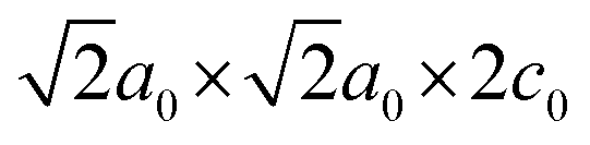 and
and  unit cells, respectively;
  for the C2/m and Cmca phases, possessing 2a0 × 2a0 × c0 and 2a0 × 2a0 × 2c0 unit cells, respectively; and ã = a for the P4/mmm phase. The normalized out-of-plane lattice constants are defined as
 ![[c with combining tilde]](https://www.rsc.org/images/entities/i_char_0063_0303.gif) = c for the P21am and P4/mmm phases, = c
= c for the P21am and P4/mmm phases, = c![[thin space (1/6-em)]](https://www.rsc.org/images/entities/i_char_2009.gif) sin
sin![[thin space (1/6-em)]](https://www.rsc.org/images/entities/char_2009.gif) β for the C2/m phase, and = c/2 for the I2cm and Cmca phases. The normalized in-plane and out-of-plane lattice constants, ã and , were plotted as a function of temperature in Fig. 4a and b. Both the in-plane and out-of-plane lattice constants exhibit an increase with increasing averaged radius of the A′-site cations, leading to an increase in the normalized cell volume defined as Ṽ = ã2, as shown in Fig. 4c. It is obvious that the lattice constants of each phase increase upon heating for all the compositions overall due to thermal expansion. To observe phase transitions more clearly, changes in volume over changes in temperature,
β for the C2/m phase, and = c/2 for the I2cm and Cmca phases. The normalized in-plane and out-of-plane lattice constants, ã and , were plotted as a function of temperature in Fig. 4a and b. Both the in-plane and out-of-plane lattice constants exhibit an increase with increasing averaged radius of the A′-site cations, leading to an increase in the normalized cell volume defined as Ṽ = ã2, as shown in Fig. 4c. It is obvious that the lattice constants of each phase increase upon heating for all the compositions overall due to thermal expansion. To observe phase transitions more clearly, changes in volume over changes in temperature,  , were plotted as a function of temperature in Fig. S11 (ESI†). The
  values exhibit anomalies at the phase transition temperatures. Such discrete changes in the lattice constants indicate first-order phase transitions. The
  anomalies are more obvious for the polar-to-nonpolar phase transitions than for the nonpolar-to-nonpolar phase transitions, indicating that the unit-cell expansion is significant for polar-to-nonpolar phase transitions.
 | ||
| Fig. 4 Normalized in-plane and out-of-plane lattice constants, (a) ã and (b) , respectively, and (c) normalized unit-cell volume as a function of temperature for all the solid solutions Cs1−xRbxNdNb2O7 with x = 0, 0.25, 0.5, 0.75, and 1. | ||
Phase transitions detected by DSC
DSC measurements were conducted on both heating and cooling processes to observe the thermal behavior across phase transitions including reversibility and hysteresis. Fig. 5a depicts the DSC curves for all the compositions and Fig. S12 (ESI†) shows the details around peaks. Endothermic and exothermic peaks are observed upon heating and cooling, respectively, around the polar-to-nonpolar I2cm-to-Cmca or P21am-to-C2/m phase transition temperatures, indicating the reversibility of the phase transitions. The averaged values of endothermic and exothermic peak temperatures are summarized in Table S17 (ESI†) for Cs1−xRbxNdNb2O7 with x = 0, 0.25, 0.5, 0.75, and 1, which are close to the polar-to-nonpolar phase transition temperatures obtained by the SXRD data. The endothermic peak temperatures upon heating are higher than the exothermic peak temperatures upon cooling. The thermal hysteresis behavior indicates that the polar-to-nonpolar phase transitions are first-order. Meanwhile, no obvious peaks are observed for other nonpolar-to-nonpolar phase transitions. The large latent heats for the polar-to-nonpolar phase transitions are reflected by the sharp changes in lattice constants for the polar-to-nonpolar phase transitions, as observed in Fig. S11 (ESI†). The smooth changes in lattice constants across the nonpolar-to-nonpolar phase transitions reflect small latent heats, hampering the peaks in the DSC curves. | ||
| Fig. 5 Multiple variable-temperature measurements for detecting phase transitions. (a) DSC and (b) SHG signals and (c) permittivity as a function of temperature for Cs1−xRbxNdNb2O7 with x = 0, 0.25, 0.5, 0.75, and 1. The red and blue arrows indicate the polar-to-nonpolar phase transition temperatures during the heating and cooling processes, respectively. | ||
Noncentrosymmetry probed by optical SHG
Optical SHG is one of the most useful probes of noncentrosymmetry.1,2 Variable-temperature SHG measurements were performed to confirm the polar-to-nonpolar I2cm-to-Cmca and P21am-to-C2/m phase transitions for Rb-rich and Cs-rich pellet samples, respectively. Fig. 5b depicts the temperature-dependent optical SHG signals for all the compositions. Finite SHG signals at room temperature agree with the SXRD results showing that all the samples adopt polar structures. The SHG signals become lower upon heating, and steeply go down to negligible values near the polar-to-nonpolar phase transition temperatures, corroborating the emergence of inversion symmetry. The thermal hysteresis between heating and cooling curves reveals the first-order phase transitions for this system, consistent with the DSC analysis. The polar-to-nonpolar phase transition temperatures detected by SHG are summarized in Table S17 (ESI†). These temperatures are also consistent with those determined by SXRD and DSC.Temperature dependence of permittivity
Other common methods to reveal polar-to-nonpolar phase transitions include variable-temperature permittivity measurements. Fig. 5c plots the permittivity for all the compositions as a function of temperature. The permittivity curves show cusps at the polar-to-nonpolar phase transition temperatures for all the samples, and Fig. S13 (ESI†) shows detailed peak positions. The polar-to-nonpolar phase transition temperatures are summarized in Table S17 (ESI†). The observed thermal hysteresis is consistent with the DSC and SHG results. The Cs-rich CsNdNb2O7 and Cs0.75Rb0.25NdNb2O7 samples exhibit a steep rise in the permittivity near the phase transition temperatures between the C2/m and P4/mmm phases, accompanied by an increase in dielectric loss (see Fig. S14a and b, ESI†), whereas such a sudden rise is not observed for the Rb-rich samples (see Fig. S14c–e, ESI†). Fig. S15 (ESI†) presents the low-temperature permittivity and dielectric loss. The absence of anomaly at low temperatures indicates that the room-temperature phases persist down to 5 K.Microstructure of the ceramic samples and demonstration of ferroelectricity
A plan-view SEM image for a Cs0.5Rb0.5NdNb2O7 ceramic pellet depicted in Fig. 6a reveals a dense packing of plate-like crystalline particles, consistent with a high relative density of 95%. Sintered ceramic samples with other compositions also exhibit a dense particle packing as shown in Fig. S16 (ESI†). P–E curves were recorded for the pellet samples at 77 K and room temperature to reveal the ferroelectric properties. Fig. 6b depicts the P–E curves for Cs0.5Rb0.5NdNb2O7 measured at room temperature with various electric-field amplitudes, as representative data. The observed hysteresis curves demonstrate ferroelectricity at room temperature. Fig. 6c shows the remanent P–E curves measured at room temperature. The remanent polarization is 0.7 μC cm−2 with an electric-field amplitude of 100 kV cm−1 at room temperature. As shown in Fig. S17 (ESI†), the hysteretic behavior of remanent P–E curves was observed at room temperature for all the compositions, demonstrating their room-temperature ferroelectricity. The room-temperature remanent polarization values increase with increasing Rb concentrations, as shown in Fig. 6d. This tendency was observed for DJ CsSmNb2O7 and RbSmNb2O7, the room-temperature polarization values of which are 2.0 μC cm−2 at 70 kV cm−1 and 5.3 μC cm−2 at 60 kV cm−1, respectively.37 Fig. S18a and b (ESI†) depict the coercive fields at 77 K and room temperature as a function of the Rb concentrations. The coercive fields do not strongly depend on temperature. The hysteresis loops observed at 77 K for all the solid solutions shown in Fig. S17 (ESI†) reveal that the polar P21am or I2cm structures are kept at low temperatures, in good agreement with the low-temperature permittivity curves. | ||
| Fig. 6 Microstructure observation and ferroelectric switching experiments. (a) Plan-view scanning electron microscope (SEM) image for the Cs0.5Rb0.5Nb2O7 ceramic pellet. (b) Polarization-electric field (P–E) curve and (c) remanent P–E curve for Cs0.5Rb0.5Nb2O7. (d) Averaged remanent polarization for Cs1−xRbxNdNb2O7 (x = 0, 0.25, 0.5, 0.75, and 1). | ||
Discussion
Compositional variation of polar distortions
Here, let us discuss the compositional variation of polar distortions in Cs1−xRbxNdNb2O7. The I2cm and P21am symmetries are established by a direct sum of irreps A2+ ⊕ A5− and M2+ ⊕ M5−, respectively. Here, the M2+ and M5− distortion modes in the P21am structure correspond to an a0a0c+-type of rotation and an a−a−c0-type of tilting, respectively. The combination of these OORs induces a polar distortion mode transforming like irrep Γ5− through a trilinear coupling term in the free energy Ftri ∝ η(M2+)η(M5−)η(Γ5−), that is, a HIF mechanism. Meanwhile, the A2+ and A5− modes in the I2cm structure correspond to an a0a0c+/a0a0−c+-type of rotation and an a−a−c0/−(a−a−)c0-type of tilting, respectively. The coupling of these OORs yields the Γ5− polar mode due to a similar trilinear coupling to that in the P21am structure.Here, the polar distortions are analyzed by decomposing the polar displacements into the contributions from each cation. The polar displacements of cations are defined as the relative positions of cations with respect to the mass centers of coordination oxygen polyhedra projected into the polar a axis, where A′O8 cuboids, NdO12 dodecahedra, and NbO6 octahedra are regarded as the coordination oxygen polyhedra. Fig. 7 depicts the polar displacements of each cation. Overall, the displacements of high-valent A-site Nd3+ and B-site Nb5+ ions are larger than those of monovalent A′-site Cs+/Rb+ ions. This indicates that the contributions of A-site and B-site cations to polarization are larger than those of A′-site ions, in good agreement with the previous first-principles calculations for Pmc21 CsLaNb2O7.48 The displacements of Nd and A′-site ions show a maximum for Cs0.5Rb0.5LaNb2O7, while that of Nb ions becomes the largest for Cs0.75Rb0.25LaNb2O7. These results appear to be in contrast with the behavior of remanent polarization, which monotonously increases with increasing Rb content (see Fig. 6d). The discrepancy partly stems from the fact that the measured polarizations were still not saturated at our maximum electric fields. In addition, the particle size and shape depend on the Rb contents as shown in the SEM images (see Fig. S16, ESI†). Such microstructure difference can influence the magnitude of polarization, resulting in the absence of correlation between crystal structures and measured polarization values.
 | ||
| Fig. 7 Polar cation displacements defined as the relative positions of cations with respect to the mass centers of coordination anion polyhedra projected into the polar a axis in Cs1−xRbxNdNb2O7 (x = 0, 0.25, 0.5, 0.75, and 1). | ||
Temperature-composition phase diagram
In the last part of this paper, let us discuss the influence of A′-site ions on the phase stability and phase transition temperatures. Fig. 8 illustrates the phase diagram of the Cs1−xRbxNdNb2O7 system constructed based on the SXRD, DSC, optical SHG, and permittivity results. The shaded area indicates the region where the tetragonal I4/mcm phase was previously reported, although it has not been detected by our SXRD study probably due to the poor sensitivity of oxygen positions. The phase boundary between the P21am and I2cm (C2/m and Cmca) phases falls within the range from 25 to 50 mol% of Rb concentration, as represented by the light-colored area. | ||
| Fig. 8 Temperature-composition phase diagram of the Cs1−xRbxNdNb2O7 system. | ||
As for the Cs-rich group including CsNdNb2O7 and Cs0.75Rb0.25NdNb2O7, the nonpolar-to-nonpolar (C2/m-to-P4/mmm) phase transition temperatures become lower with increasing Rb concentrations, whereas the polar-to-nonpolar (P21am-to-C2/m) ferroelectric transition temperatures are slightly enhanced with higher Rb concentrations. As for the Rb-rich group including Cs1−xRbxNdNb2O7 with x = 0.5, 0.75, and 1, both the nonpolar-to-nonpolar Cmca-to-P4/mmm and polar-to-nonpolar I2cm-to-Cmca phase transition temperatures become higher with increasing Rb concentrations. In both the groups, the polar-to-nonpolar phase transitions are accompanied by a change in the number of OOR axes from three to two, while the nonpolar-to-nonpolar phase transitions involve a reduction of the number of OOR axes from two to zero. It is commonly understood that the OOR instability increases with decreasing A-site cation's radii in perovskite-related compounds, letting us infer that both the polar-to-nonpolar and nonpolar-to-nonpolar phase transition temperatures monotonously increase with increasing Rb concentrations. However, the two phase-transition temperatures of the solid solutions do not show a monotonous increase with an increase in the Rb concentration across a whole compositional range, largely deviating from Vegard's law with non-negligible downward bowing. This is most likely because the random arrangement of the A′-site Cs and Rb ions leads to structural frustration effects on the emergence of OORs. The Cs ions prefer the same sense of OORs (a−a−c+/a−a−c+) in the adjacent double-perovskite layers, whereas the Rb ions favor the opposite sense of OORs (a−a−c+/−(a−a−c+)); the stable OOR patterns cannot be readily determined when the Cs and Rb ions are randomly placed at the A′ sites, suppressing the phase transitions. This behavior is reminiscent of the suppression of magnetic phase transition in magnetically frustrated systems, which involve the coexistence of ferromagnetic and antiferromagnetic interactions or the geometric magnetic frustration due to the antiferromagnetic triangles as in kagome and pyrochlore lattices.49,50 Thus, the OOR instability in the solid solutions is affected not only by the size of A′-site cations but also the structural frustration effects due to the mixed alkali metal ions in the intervening layers. Such a deviation from Vegard's laws is in stark contrast to a monotonous variation of Curie temperatures with Zr contents in the HIF complete solid solution system Sr3(Sn1−xZrx)2O7, the end members of which adopt the same OOR patterns and hence no structural frustration effects.42
Conclusions
In summary, DJ double-layered perovskite Cs1−xRbxNdNb2O7 complete solid solutions were obtained by high-temperature solid-state reaction methods. The temperature-composition phase diagram was determined by combining the variable-temperature SXRD, DSC, optical SHG, and permittivity measurements. The Cs-rich samples (x ≤ 0.25) crystalize into the polar P21am structures at room temperature, while the Rb-rich samples (x ≥ 0.5) adopt the I2cm structures. Ferroelectricity was demonstrated for all the compositions at room temperatures. The room-temperature remanent polarization values increase monotonously as the Rb contents increase, although the polar displacements of cations do not exhibit such a monotonous dependence on Rb contents. The Cs-rich samples undergo the thermally-induced phase transitions from the P21am to C2/m to P4/mmm phases, while the Rb-rich samples exhibit the phase transitions pathway from the I2cm to Cmca to P4/mmm phases on heating. Both the polar-to-nonpolar and nonpolar-to-nonpolar phase transition temperatures for the solid solutions with intermediate compositions are lower than the interpolated values from the two end members. The deviation from a Vegard's law is likely to stem from structural frustration effects due to the random arrangement of two types of alkali metal ions at the A′ sites. This work gives insight into a role of the intervening A′-site alkali metal ions in the crystal structures and ferroelectric properties of HIF DJ double-layered perovskites.Data availability
The data associated with this article are available in the manuscript and its ESI.†Conflicts of interest
There are no conflicts to declare.Acknowledgements
This research was supported by the Japan Society of the Promotion of Science (JSPS) KAKENHI Grants (No. JP17K19172, JP18H01892, JP21K19027, JP21H05568, JP21H04619, and JP23H01869), the Murata Science Foundation, and Collaborative Research Project of Laboratory for Materials and Structures, Institute of Innovative Research, Tokyo Institute of Technology. Z. L. was financially supported by Chinese Scholarship Council (No. 202008320325). S. Y. and V. G. were supported by the National Science Foundation Grant number NSF DMR-2210933. The synchrotron radiation experiments were performed at the BL02B2 of SPring-8 with the approval of the Japan Synchrotron Radiation Research Institute (JASRI) (Proposal No. 2018A1152, 2018B1227, 2023A1875, and 2023B2047).References
- J.-N. Li, X.-H. Li, W.-D. Yao, W. Liu and S.-P. Guo, Chem. Commun., 2021, 57, 5175–5178 RSC.
- Z.-T. Lu, W.-J. Fan, Z.-Q. Wang, N. Gu, Z.-H. Yue, H.-G. Xue and S.-P. Guo, Inorg. Chem., 2020, 59, 7905–7909 CrossRef CAS.
- M. B. Smith, K. Page, T. Siegrist, P. L. Redmond, E. C. Walter, R. Seshadri, L. E. Brus and M. L. Steigerwald, J. Am. Chem. Soc., 2008, 130, 6955–6963 CrossRef CAS PubMed.
- S. Yoshida, H. Akamatsu, R. Tsuji, O. Hernandez, H. Padmanabhan, A. Sen Gupta, A. S. Gibbs, K. Mibu, S. Murai, J. M. Rondinelli, V. Gopalan, K. Tanaka and K. Fujita, J. Am. Chem. Soc., 2018, 140, 15690–15700 CrossRef CAS PubMed.
- T. Weigel, C. Ludt, T. Leisegang, E. Mehner, S. Jachalke, H. Stöcker, T. Doert, D. C. Meyer and M. Zschornak, Phys. Rev. B, 2023, 108, 054105 CrossRef CAS.
- L. N. Kholodkovskaya, V. A. Dolgikh and B. A. Popovkin, J. Solid State Chem., 1995, 116, 406–408 CrossRef CAS.
- S. Trolier-McKinstry, S. Zhang, A. J. Bell and X. Tan, Annu. Rev. Mater. Res., 2018, 48, 191–217 CrossRef CAS.
- F. Gao, L. Cheng, R. Hong, J. Liu, C. Wang and C. Tian, Ceram. Int., 2009, 35, 1719–1723 CrossRef CAS.
- L. Qi, S. Ruan and Y.-J. Zeng, Adv. Mater., 2021, 33, 2005098 CrossRef CAS.
- Z. Guan, H. Hu, X. Shen, P. Xiang, N. Zhong, J. Chu and C. Duan, Adv. Electron. Mater., 2020, 6, 1900818 CrossRef CAS.
- A. S. Gupta, H. Akamatsu, M. E. Strayer, S. Lei, T. Kuge, K. Fujita, C. dela Cruz, A. Togo, I. Tanaka, K. Tanaka, T. E. Mallouk and V. Gopalan, Adv. Electron. Mater., 2016, 2, 1500196 CrossRef.
- R. Guo, L. You, Y. Zhou, Z. Shiuh Lim, X. Zou, L. Chen, R. Ramesh and J. Wang, Nat. Commun., 2013, 4, 1990 CrossRef.
- H. Lei, D. Hardy and F. Gao, Adv. Funct. Mater., 2021, 31, 2105898 CrossRef CAS.
- L. Li, P. A. Salvador and G. S. Rohrer, Nanoscale, 2014, 6, 24–42 RSC.
- C. Ederer and N. A. Spaldin, Phys. Rev. B: Condens. Matter Mater. Phys., 2006, 74, 020401 CrossRef.
- W. Gong, J.-F. Li, X. Chu, Z. Gui and L. Li, Acta Mater., 2004, 52, 2787–2793 CrossRef CAS.
- C.-L. Jia, K. W. Urban, M. Alexe, D. Hesse and I. Vrejoiu, Science, 2011, 331, 1420–1423 CrossRef CAS PubMed.
- G. Chen, K. Zou, Y. Yu, Y. Zhang, Q. Zhang, Y. Lu and Y. He, Ceram. Int., 2020, 46, 4148–4153 CrossRef CAS.
- M. Ichiki, H. Furue, T. Kobayashi, R. Maeda, Y. Morikawa, T. Nakada and K. Nonaka, Appl. Phys. Lett., 2005, 87, 222903 CrossRef.
- A. Sen Gupta, H. Akamatsu, F. G. Brown, M. A. T. Nguyen, M. E. Strayer, S. Lapidus, S. Yoshida, K. Fujita, K. Tanaka, I. Tanaka, T. E. Mallouk and V. Gopalan, Chem. Mater., 2017, 29, 656–665 CrossRef CAS.
- N. A. Benedek and C. J. Fennie, Phys. Rev. Lett., 2011, 106, 107204 CrossRef PubMed.
- E. Bousquet, M. Dawber, N. Stucki, C. Lichtensteiger, P. Hermet, S. Gariglio, J.-M. Triscone and P. Ghosez, Nature, 2008, 452, 732–736 CrossRef CAS PubMed.
- N. A. Benedek, Inorg. Chem., 2014, 53, 3769–3777 CrossRef CAS PubMed.
- N. A. Benedek and M. A. Hayward, Annu. Rev. Mater. Res., 2022, 52, 331–355 CrossRef CAS.
- J. M. Rondinelli and C. J. Fennie, Adv. Mater., 2012, 24, 1918 CrossRef CAS.
- X. Q. Liu, J. W. Wu, X. X. Shi, H. J. Zhao, H. Y. Zhou, R. H. Qiu, W. Q. Zhang and X. M. Chen, Appl. Phys. Lett., 2015, 106, 202903 CrossRef.
- S. Yoshida, K. Fujita, H. Akamatsu, O. Hernandez, A. Sen Gupta, F. G. Brown, H. Padmanabhan, A. S. Gibbs, T. Kuge, R. Tsuji, S. Murai, J. M. Rondinelli, V. Gopalan and K. Tanaka, Adv. Funct. Mater., 2018, 28, 1801856 CrossRef.
- X. Q. Liu, J. J. Lu, B. H. Chen, B. H. Zhang and X. M. Chen, J. Appl. Phys., 2019, 125, 114105 CrossRef.
- X. Xu, Y. Wang, F.-T. Huang, K. Du, E. A. Nowadnick and S.-W. Cheong, Adv. Funct. Mater., 2020, 30, 2003623 CrossRef CAS.
- K. A. Smith, S. P. Ramkumar, N. C. Harms, A. J. Clune, X. Xu, S.-W. Cheong, Z. Liu, E. A. Nowadnick and J. L. Musfeldt, Phys. Rev. B, 2021, 104, 064106 CrossRef CAS.
- A. M. Glazer, Acta Crystallogr., Sect. B, 1972, 28, 3384–3392 CrossRef CAS.
- M. W. Lufaso and P. M. Woodward, Acta Crystallogr., Sect. B:Struct. Sci., 2004, 60, 10–20 CrossRef.
- N. A. Benedek and C. J. Fennie, J. Phys. Chem. C, 2013, 117, 13339–13349 CrossRef CAS.
- S. Mallick, A. S. Gibbs, W. Zhang, P. S. Halasyamani, N. A. Benedek and M. A. Hayward, Chem. Mater., 2020, 32, 7965–7972 CrossRef CAS.
- T. Zhu, A. S. Gibbs, N. A. Benedek and M. A. Hayward, Chem. Mater., 2020, 32, 4340–4346 CrossRef CAS.
- C. Chen, H. Ning, S. Lepadatu, M. Cain, H. Yan and M. J. Reece, J. Mater. Chem. C, 2015, 3, 19–22 RSC.
- S. Pal, R. Nagarajan and S. Uma, Chem. Mater., 2023, 35, 1249–1258 CrossRef CAS.
- Z. Yan, D. Zhang, X. Zhou, M. Zhang, Y. Yue, L. Zhang, G. Xue, H. Luo, I. Abrahams and H. Yan, Acta Mater., 2020, 200, 971–979 CrossRef CAS.
- M. E. Strayer, A. S. Gupta, H. Akamatsu, S. Lei, N. A. Benedek, V. Gopalan and T. E. Mallouk, Adv. Funct. Mater., 2016, 26, 1930–1937 CrossRef CAS.
- B.-W. Li, M. Osada, T. C. Ozawa and T. Sasaki, Chem. Mater., 2012, 24, 3111–3113 CrossRef CAS.
- T. Zhu, T. Cohen, A. S. Gibbs, W. Zhang, P. S. Halasyamani, M. A. Hayward and N. A. Benedek, Chem. Mater., 2017, 29, 9489–9497 CrossRef CAS.
- Q. S. Chen, B. H. Zhang, B. H. Chen, X. Q. Liu and X. M. Chen, J. Appl. Phys., 2022, 131, 184102 CrossRef CAS.
- S. Kawaguchi, M. Takemoto, K. Osaka, E. Nishibori, C. Moriyoshi, Y. Kubota, Y. Kuroiwa and K. Sugimoto, Rev. Sci. Instrum., 2017, 88, 085111 CrossRef CAS PubMed.
- J. Rodríguez-Carvajal, Phys. B, 1993, 192, 55–69 CrossRef.
- K. Momma and F. Izumi, J. Appl. Cryst., 2008, 41, 653–658 CrossRef CAS.
- N. E. Brese and M. O’Keeffe, Acta. Crystallogr., Sect. B:Struct. Sci., 1991, 47, 192–197 CrossRef.
- S. Asaki, H. Akamatsu, G. Hasegawa, T. Abe, Y. Nakahira, S. Yoshida, C. Moriyoshi and K. Hayashi, Jpn. J. Appl. Phys., 2020, 59, SPPC04 CrossRef CAS.
- N. A. Benedek, J. M. Rondinelli, H. Djani, P. Ghosez and P. Lightfoot, Dalton Trans., 2015, 44, 10543–10558 RSC.
- A. P. Ramirez, Annu. Rev. Mater. Res., 1994, 24, 453–480 CrossRef CAS.
- J. A. Mydosh, Spin Glasses: An Experimental Introduction, CRC Press, London, 2014 Search PubMed.
Footnote |
| † Electronic supplementary information (ESI) available. See DOI: https://doi.org/10.1039/d4tc04190a |
| This journal is © The Royal Society of Chemistry 2025 |