
 Open Access Article
 This Open Access Article is licensed under a Creative Commons Attribution-Non Commercial 3.0 Unported Licence
Topology-dependent T2 relaxivity in Fe3O cluster-based MOFs for enhanced tumor monitoring via MRI†
Qiao
Wang
,
Yimin
Gong
,
Jianing
Li
,
Dan
Luo
,
Xin
Zeng
,
Yun
Ling
 *,
Yaming
Zhou
and
Zhenxia
Chen
*
*,
Yaming
Zhou
and
Zhenxia
Chen
*
Shanghai Key Laboratory of Molecular Catalysis and Innovative Materials, Department of Chemistry, Fudan University, Shanghai, 200433, China. E-mail: yunling@fudan.edu.cn; zhxchen@fudan.edu.cn
First published on 20th March 2025
Abstract
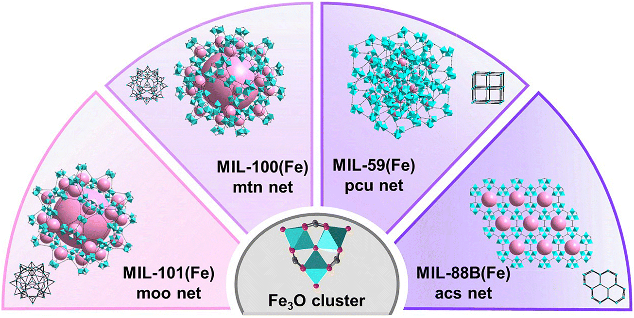
Metal–organic frameworks (MOFs) are crystalline porous materials with tunable structures, where metal ions or clusters serve as magnetic centers and organic ligands offer spatial separation. These characteristics, combined with their diverse topologies, make MOFs promising candidates for contrast agents (CAs) in magnetic resonance imaging (MRI). Herein we synthesized four MOFs based on the same triangular Fe3O clusters with different topologies: MIL-101(Fe) (moo net), MIL-100(Fe) (mtn net), MIL-59(Fe) (pcu net), and MIL-88B(Fe) (acs net). To clarify the relationship between topologies and T2 relaxivities, the MOFs were tailored into uniform, nanoscale spherical morphologies. Notably, the value of T2 relaxivity for MIL-88B(Fe) with acs topology is nearly three times that for MIL-101(Fe) with moo topology at 7.0 T. By comparing the magnetic properties of Fe3O molecular clusters and Ga-doped MIL-88B(Fe), our analysis demonstrated the significant advantage of MOFs with fixed arrays, adjustable components and diverse topologies in enhancing magnetic relaxation. Cellular MRI experiments further revealed that MIL-88B(Fe) could differentiate between M1 and M2 macrophages, highlighting its potential for monitoring tumor progression. These findings offer valuable insights into how MOF topology can be strategically utilized to enhance T2 relaxivities for MRI applications.
1. Introduction
Magnetic resonance imaging (MRI) has become an indispensable tool in clinical research fields due to its ability to non-invasively obtain high-resolution images of internal structures and functions.1–3 To enhance the contrast of images, particularly in deep tissue imaging, the use of contrast agents (CAs) is essential.4 Early CAs were primarily molecular-based, such as gadolinium5 and iron compounds.6 These agents work by altering the relaxation times of nearby water protons, thus improving the image quality. The magnetic resonance (MR) signals are largely influenced by several factors, including the molecular composition and the relaxation properties of the agent itself.7 The developments of nanotechnology have enabled the synthesis of nanoscale molecular assemblies, significantly improving the MRI performance by the aggregation effects from CAs.8,9 In addition to the aggregation effect, the size and morphology of CAs also play a crucial role in determining the efficiency of CAs.10 For example, Cheon et al. discovered that the T2 relaxivity of iron oxide nanoparticles (IONPs) shows a clear dependence on their sizes.11 Similarly, Zhao et al. demonstrated that octapod-shaped IONPs exhibit a T2 relaxivity 5.4 times higher than that of spherical IONPs of comparable volume.12 Conceptualizing the magnetic center of a CA as a domain, the lattice structure and domain arrangement within a nanoparticle can significantly influence its MRI properties, making the regulation of domains a critical factor in optimizing CA performance. However, traditional dense structures based on rigid oxygen-bridges make precise control over internal magnetic domains unfeasible. These limitations emphasize the need for alternative materials to address the drawbacks of conventional IONPs in MRI research.Metal–organic frameworks (MOFs) are crystalline porous materials constructed from organic linkers and metal ions/clusters, exhibiting well-defined structures and exceptional chemical tenability.13,14 MOFs offer a promising platform for the development of novel CAs with tailorable properties.15,16 Research studies on MOFs have demonstrated that relaxivity increases in a size-dependent manner.17,18 Khoobi et al. reported that the measured proton relaxation rates and contrast enhancement strongly depend on the size and aspect ratio of MIL-88B.19 The nano-sized metal clusters within MOFs serve as magnetic centers, while the organic ligands can modify the coordination environment and connectivity between metal centers, allowing for precise control over the relaxivity of CAs.20 For example, Rathnayake et al. synthesized porous microstructures of isoreticular Fe-based MOFs (Fe-MOFs) and confirmed that the magnetic response is induced strictly by the localized electron density and spin density of states on Fe3O domains.21 Although the diverse topologies of MOFs provide a unique opportunity to investigate how structural variation impacts MRI performance, a comprehensive understanding of the magnetism within MOFs for MRI research has not yet been fully explored. Given the unique architecture, MOFs represent an ideal platform to study and manipulate magnetic properties, meeting the essential structural criteria for advanced MRI applications.
In this work, we focus on the design and synthesis of MOFs featuring triangular Fe3O clusters as magnetic lattices. These metal-oxo clusters, characterized by spin-canted magnetic interactions, are highly sensitive to structural changes, making them ideal candidates for studying topology-dependent effects on MR properties.22,23 Four Fe-MOFs with distinct topologies, MIL-101(Fe) (moo net), MIL-100(Fe) (mtn net), MIL-59(Fe) (pcu net), and MIL-88B(Fe) (acs net), were successfully synthesized.24–27 To minimize the influence of crystal face variations and magnetic anisotropy on T2 relaxivities, we regulated the morphologies of four Fe-MOFs into isotropic spherical nanoparticles. From MIL-101(Fe) to MIL-88B(Fe), as the Fe3O cluster density increased, we observed a gradual rise in both saturation magnetization and T2 relaxivity. The value of T2 relaxivity for MIL-88B(Fe) with acs topology is nearly three times that for MIL-101(Fe) with moo topology in 7.0 T. We further characterized the magnetic properties of Fe3O molecular clusters and Ga-doped MIL-88B(Fe) for comparison. The results demonstrated the significant advantage of MOFs with fixed arrays, adjustable components and diverse topologies in enhancing magnetic relaxation. Finally, we demonstrated that MIL-88B(Fe) effectively distinguishes between M1 and M2 macrophages, highlighting its potential for monitoring tumor progression and showcasing its promise as a CA in MRI applications.
2. Results and discussion
2.1. Synthesis and characterization of four Fe-MOFs
Four Fe-MOFs were synthesized based on previously reported methods. Scheme 1 illustrates the distinct structures and topologies of these four Fe-MOFs constructed from the same Fe3O cluster. As shown in Fig. 1a, the powder X-ray diffraction (PXRD) patterns matched well with the simulated patterns of MIL-101(Fe), MIL-100(Fe), MIL-59(Fe), and MIL-88B(Fe), confirming their high crystallinity and phase purity. Thermogravimetric curves of all four Fe-MOFs (Fig. S1, ESI†) exhibited three main weight loss stages: an initial 10% loss of around 100 °C, likely due to surface moisture; a second 40% loss between 100 and 500 °C, attributed to the decarboxylation of organic linkers, leading to framework collapse; and a final loss from 550 to 650 °C, marking complete framework decomposition. The nitrogen adsorption isotherms of MIL-101(Fe), MIL-100(Fe), MIL-59(Fe), and MIL-88B(Fe) are presented in Fig. 1b, with Brunauer–Emmett–Teller (BET) surface areas calculated as 2040, 1219, 300 and 37 m2 g−1, respectively. These adsorption results are consistent with previous reports, showing that MIL-101(Fe) and MIL-100(Fe) exhibit well-defined large micropores, while MIL-59(Fe) and MIL-88B(Fe) exhibit dense, nonporous structures. Additionally, the FT-IR spectra of all four Fe-MOFs displayed a characteristic C![[double bond, length as m-dash]](https://www.rsc.org/images/entities/char_e001.gif) O stretching vibration peak in the range of 1600–1700 cm−1, indicating the presence of carboxylate-containing organic ligands (Fig. S2, ESI†).
O stretching vibration peak in the range of 1600–1700 cm−1, indicating the presence of carboxylate-containing organic ligands (Fig. S2, ESI†).
 | ||
| Scheme 1 Schematic illustration of the Fe3O cluster and Fe-MOFs with different topologies. | ||
 | ||
| Fig. 1 (a) PXRD patterns, (b) N2 adsorption–desorption isotherms at 77 K, (c) XPS spectra of Fe 2p levels, and (d) XPS spectra of MIL-101(Fe), MIL-100(Fe), MIL-59(Fe), and MIL-88B(Fe). | ||
X-ray photoelectron spectroscopy (XPS) survey spectra, along with the corresponding binding energy spectra, of each element in four Fe-MOFs, are shown in Fig. 1c and d. These spectra provided further evidence for the successful synthesis of four Fe-MOFs, with iron existing in a trivalent oxidation state within the Fe3O clusters. The XPS data clearly demonstrate the presence of Fe, C, and O, in agreement with the expected composition. These results confirm the successful incorporation of iron(III) into the MOF structure, along with high purity and structural integrity.
To eliminate the effects of crystal faces and magnetic anisotropy, we regulated all four Fe-MOFs into uniform spherical nanoparticles of similar sizes. The morphology of four Fe-MOFs was thoroughly confirmed using scanning electron microscopy (SEM) and transmission electron microscopy (TEM). As shown in Fig. S3 (ESI†), the SEM images reveal that all four Fe-MOFs exhibited highly uniform particle sizes of approximately 150 nm, maintaining a well-defined spherical shape. TEM images also confirmed the spherical, uniform particle morphology, as shown in Fig. 2. TEM-EDS mapping displayed the homogeneous distribution of key elements, including Fe, C, and O, across the entire surface of the Fe-MOFs. This even dispersion suggests stable frameworks and further supports the successful formation of four Fe-MOFs with desired structural integrity. Collectively, all characterization techniques confirm the successful synthesis of four Fe-MOFs with distinct topologies, well-defined crystallinity and a uniform spherical morphology with consistent nanoparticle sizes.
 | ||
| Fig. 2 TEM, HAADF-STEM, and EDX mapping images of MIL-101(Fe), MIL-100(Fe), MIL-59(Fe), and MIL-88B(Fe). | ||
2.2. T 2 relaxivities, T2-weighted imaging in vitro
The T2 relaxivities of four Fe-MOFs with distinct topologies were measured under two different magnetic field strengths at 3.0 T and 7.0 T, respectively (Fig. 3a and b). Transverse relaxivity (r2) was determined by fitting the relaxation rate as a function of concentration. At 3.0 T, the r2 values of MIL-101(Fe), MIL-100(Fe), MIL-59(Fe), and MIL-88B(Fe) were calculated as 1.51 mL mg−1 s−1, 2.74 mL mg−1 s−1, 6.04 mL mg−1 s−1, and 8.76 mL mg−1 s−1, respectively. These values show that MIL-88B(Fe) with acs topology exhibits the highest T2 relaxivity among the four Fe-MOFs at this field strength, suggesting a strong influence of topology on magnetic resonance properties. To further investigate the impact of magnetic field strength, measurements were repeated at 7.0 T. The r2 values at this field were significantly increased to 16.43 mL mg−1 s−1 for MIL-101(Fe), 28.51 mL mg−1 s−1 for MIL-100(Fe), 35.03 mL mg−1 s−1 for MIL-59(Fe), and 40.28 mL mg−1 s−1 for MIL-88B(Fe), respectively. The markable r2 value increases at 7.0 T indicating a pronounced sensitivity of T2 relaxivity to magnetic field strength.7 Moreover, the consistent upward trend in r2 values across the series, from MIL-101(Fe) to MIL-88B(Fe) at both 3.0 T and 7.0 T, highlights the critical role of MOF topology in influencing their relaxometric behavior under various magnetic fields. | ||
| Fig. 3 T 2 relaxivities plot of MIL-101(Fe), MIL-100(Fe), MIL-59(Fe), and MIL-88B(Fe) at (a) a 3.0 T MR system and (b) a 7.0 T MR system. (c) T2-Weighted MR images of MIL-101(Fe), MIL-100(Fe), MIL-59(Fe), and MIL-88B(Fe) aqueous solution at (c) a 3.0 T MR system and (d) a 7.0 T MR system. | ||
As shown in Fig. 3c and d, the T2 contrast effects of the four Fe-MOFs were also evaluated at both 3.0 T and 7.0 T, revealing a strong correlation between their topologies and MRI performance. Generally, Fe-MOFs with large pore sizes and surface areas, such as MIL-101(Fe) and MIL-100(Fe), exhibited relatively weak T2 contrast effects. This may be attributed to the reduced efficiency of signal attenuation at low iron concentrations, suggesting that their porous structures limit sensitivity in T2-weighted imaging. In contrast, Fe-MOFs with small pore sizes and dense iron contents, such as MIL-59(Fe), demonstrate a significantly enhanced T2 contrast effect, likely due to more efficient magnetic interactions. MIL-88B(Fe), with the densest iron content, displayed the strongest T2 contrast effect among the four Fe-MOFs. Notably, even at a low concentration of 0.0625 mg mL−1 at 7.0 T, MIL-88B(Fe) produced a distinctly dark signal, underscoring its potential for high-sensitivity MRI and precise diagnostic applications.
To further investigate the role of MOF framework in enhancing T2 relaxivity, a discrete molecular Fe3O cluster structure, [Fe3O(O2CPh)6(H2O)3]·ClO4, which contains the same Fe3O core as the Fe-MOFs, was synthesized and characterized (Fig. S4, ESI†). An in vitro MRI study revealed a r2 value of only 9.48 mL mg−1 s−1 at 7.0 T, significantly lower than all four Fe-MOFs. This result suggests that the well-defined arrangement of Fe3O clusters within the MOF framework does enhance the T2 relaxivity, likely due to the structural effects of an extended network, which promote more effective magnetic relaxation.
Furthermore, the inherent spin frustration in Fe-MOFs can significantly limit their magnetic properties and reduce their effectiveness in magnetic resonance applications. To mitigate this issue, we selected MIL-88B(Fe) as a representative model and strategically substituted a portion of Fe3+ ions with non-magnetic Ga3+ ions. PXRD patterns as shown in Fig. 4a confirm that the crystalline structure and phase purity of MIL-88B remain intact across different Ga3+ doping levels. This substitution disrupts the spin-frustrated state by aligning the remaining two Fe3+ ions in an antiparallel configuration, thereby achieving a lower energy state. However, while this modification reduces spin frustration, it also partially cancels the material's magnetic properties due to the opposing spin orientations of the iron ions. Interestingly, when two Fe3+ ions are replaced by Ga3+ ions, leaving only one magnetic Fe3+ ion per cluster, the resulting structure exhibits the highest magnetic moment, as illustrated in Fig. 4b. This suggests that fine-tuning the doping ratio can optimize the magnetic properties by minimizing spin frustration while preserving or enhancing the overall magnetic moment. We then evaluated the T2 relaxivities of MIL-88B(Fe), MIL-88B(Fe2Ga), and MIL-88B(FeGa2) at 7.0 T to assess the impact of Ga3+ doping on their magnetic resonance properties. As shown in Fig. 4c, the r2 values increased progressively with higher gallium content, from 40.28 mL mg−1 s−1 for MIL-88B(Fe), 46.58 mL mg−1 s−1 for MIL-88B(Fe2Ga) to 53.18 mL mg−1 s−1 for MIL-88B(FeGa2). The T2-weighted MR images in Fig. 4d further support these findings. As the Ga3+ concentration increases, the signal intensity decreases, consistent with stronger T2 contrast effects. Partial Ga3+ doping in Fe-MOFs suggests that the modified electronic environment around Fe3+ ions promotes more efficient magnetic relaxation, thus improving the material's performance as an MRI CA.
 | ||
| Fig. 4 (a) PXRD patterns of MIL-88B(Fe), MIL-88B(Fe2Ga), and MIL-88B(FeGa2). (b) Schematic illustration of MIL-88B with different metal doping ratios. (c) T2 relaxivities plot, and (d) T2-weighted MR images of MIL-88B(Fe), MIL-88B(Fe2Ga), and MIL-88B(FeGa2). | ||
2.3. Magnetic properties
To further validate the magnetic properties of the four Fe-MOFs, magnetic hysteresis (M–H) measurements were conducted at 300 K (Fig. 5a), revealing their superparamagnetic behaviors. Notably, the saturation magnetization values exhibited a clear trend, increasing from 0.066 emu g−1 in MIL-101(Fe) to 0.27 emu g−1 in MIL-88B(Fe) (Fig. 5b). To better understand these magnetic properties, it is essential to analyze the electronic structures of four Fe-MOFs. The insulating behavior of Fe-MOFs arises from the limited overlap between the d-orbitals of the metal centers and the pz orbitals of the organic ligands, which restricts electron delocalization. As a result, the electron density remains localized within the Fe3O clusters, forming isolated magnetic domains within the MOF crystal structure.21,28 In the absence of an external magnetic field, thermal fluctuations cause random orientations of the Fe3O clusters, yielding no net magnetism. However, under an applied magnetic field, the Fe3O clusters align, producing a collective magnetic response. The topology of Fe-MOFs predominantly governs this alignment, thereby shaping their magnetic properties. With topologies that accommodate higher Fe3O cluster densities, the magnetic moment increases, leading to a higher saturation magnetization. Herein, we defined the Fe3O cluster density as the number of Fe3O clusters per 1000 Å3, providing a quantitative foundation for subsequent calculations. As summarized in Table S2 (ESI†), the Fe3O cluster densities for MIL-101(Fe), MIL-100(Fe), MIL-59(Fe), and MIL-88B(Fe) were calculated as 0.3989, 0.7098, 1.115, and 1.347 per 1000 Å3, respectively, reflecting a progressive increase across four Fe-MOFs. In line with this observation, XPS analysis confirms that MIL-88B(Fe) has the highest concentration of Fe atoms (Table S3, ESI†), reinforcing the relationship between Fe3O cluster density and magnetic properties. Fig. 5b shows the relationship between increasing Fe3O cluster density and enhanced saturation magnetization values. This tendency is also consistent between the Fe3O cluster density and T2 relaxivity values. | ||
| Fig. 5 (a) M–H loops of MIL-101(Fe), MIL-100(Fe), MIL-59(Fe), and MIL-88B(Fe) at 300 K. (b) T2 relaxivities and saturation magnetization versus the density of Fe3O clusters. | ||
According to the traditional quantum mechanical outer-sphere theory, materials with consistent spherical morphology and elevated saturation magnetization will exhibit higher T2 relaxivity.29–31 The equation for relaxivity (r2) is expressed as
| r2 = (256π2γ2/405)κMs2r2/D(1 + L/r) | (1) |
2.4. Cellular MRI
In subsequent experiments, a model was developed to investigate the impact of different macrophage types on the MR properties of MIL-88B(Fe). M1 and M2 macrophages exhibit distinct biochemical profiles: M1 macrophages are typically in an inflammatory state with elevated hydrogen peroxide (H2O2) levels, while M2 macrophages are associated with anti-inflammatory responses, characterized by high glutathione (GSH) levels.33 To simulate these conditions, MIL-88B(Fe) was exposed separately to H2O2 and GSH in solution. As illustrated in Fig. 6a and described by chemical eqn (2) and (3), MIL-88B(Fe) undergoes redox cycling between Fe(III) and Fe(II) when exposed to H2O2, facilitated by the oxidizing environment. This process generates a stable negative contrast effect in T2-weighted MR images over time (Fig. 6b). Conversely, when MIL-88B(Fe) is exposed to GSH, the reductive environment gradually reduces Fe(III) to Fe(II), which possesses a lower magnetic moment and fewer unpaired electrons. This reduction progressively weakens the negative contrast effect, as described by eqn (4) and observed in the MR images. The reduction of Fe(III) to Fe(II) was further confirmed by XPS (Fig. 6c and Fig. S5, S6, ESI†). After treatment with H2O2, the Fe 2p spectra exhibited peaks at approximately 711 eV and 725 eV, corresponding to the Fe(III) 2p3/2 and Fe(III) 2p1/2 binding energies, respectively. A satellite peak characteristic of Fe(II) appeared at 715.9 eV, indicating that following the reaction with H2O2, a portion of Fe(III) was reduced to Fe(II). For MIL-88B(Fe)-GSH, the binding energies of Fe 2p3/2 and Fe 2p1/2 shifted obviously to lower values following the reduction, with peaks at 709 eV and 722.4 eV corresponding to Fe(II). The satellite peak associated appeared at 715.1 eV, corresponding to the satellite peak of Fe(II). All Fe(III) nodes were reduced to Fe(II) due to the addition of an excess amount of GSH. These results provide direct evidence of the valence state change induced by GSH. Additionally, the M–H plot (Fig. 6d) demonstrated a significant decrease in saturation magnetization, further indicating that the magnetic properties of MIL-88B(Fe) were diminished after reduction by GSH.| Fe(III)-MIL-88B(Fe) + H2O2 → Fe(II)-MIL-88B(Fe) + O2 + H+ | (2) |
| Fe(II)-MIL-88B(Fe) + H2O2 → Fe(III)-MIL-88B(Fe) + ˙OH + H2O | (3) |
| GSH + Fe(III)-MIL-88B(Fe) → GSSG + Fe(II)-MIL-88B(Fe) | (4) |
 | ||
| Fig. 6 (a) Schematic illustration of the polarization of M0 macrophages into M1 and M2 macrophages, as well as the chemical reactions occurring during the co-incubation of M1 and M2 macrophages with MIL-88B(Fe)@HA. (b) T2-Weighted MR images of GSH mediated reduction of MIL-88B(Fe), alongside the simultaneous oxidation and reduction of MIL-88B(Fe) induced by H2O2 in solution at 0 h, 4 h, 6 h, 8 h, 12 h, and 24 h. (c) XPS spectra of Fe 2p levels, and (d) M–H loops at 300 K of MIL-88B(Fe) reduced by GSH. (e) T2-Weighted MR images of M1 and M2 macrophages incubated with 50 μg mL−1 MIL-88B(Fe)@HA for 0 h, 4 h, 6 h, 8 h, 12 h, and 24 h. (f) T2-Weighted MR images of the mixed solution of M1 and M2 macrophages incubated with 50 μg mL−1 MIL-88B(Fe)@HA for 24 h. | ||
Before proceeding with cellular MRI experiments, hyaluronic acid (HA) was conjugated onto MIL-88B(Fe) to enhance its biocompatibility. Zeta potential measurements in DI water confirmed successful HA conjugation, as the zeta potential shifted from +26.8 mV for MIL-88B(Fe) to −24.1 mV for MIL-88B(Fe)@HA (Fig. S7, ESI†). To further evaluate the colloidal stability of MIL-88B(Fe)@HA under biologically relevant conditions, dynamic light scattering (DLS) measurements were performed in different media. The hydrodynamic diameter was 220.2 nm in deionized water, whereas in physiological saline, it increased to 255.2 nm. This size increase can be attributed to the presence of Na+ and Cl− in saline, which compress the electrical double layer and weaken electrostatic repulsion between particles, leading to slight aggregation (Fig. S8, ESI†). To assess the cytotoxicity, MIL-88B(Fe)@HA was incubated with RAW264.7 macrophages, and cell viability was measured using the Cell Counting Kit-8 (CCK-8) assay. The cell viability results indicated that over 80% of cells remained viable at concentrations of up to 100 μg mL−1 after 24 hours of incubation, suggesting that MIL-88B(Fe)@HA exhibits low cytotoxicity (Fig. S9, ESI†). Subsequently, RAW264.7 cells were polarized into M1 and M2 macrophages using LPS and IL-4 stimulation, respectively (Fig. S10, ESI†). After incubation of these macrophages with MIL-88B(Fe)@HA over various time points (0, 4, 6, 8, 12, and 24 h), the T2 contrast effects were evaluated using a 7.0 T MRI system. As shown in Fig. 6e, MIL-88B(Fe)@HA accumulated progressively within both M1 and M2 macrophages, leading to a gradual decrease in T2 signal intensity. However, M2 macrophages exhibited a less pronounced negative contrast effect compared to M1 macrophages. This difference is attributed to the high GSH levels in M2 cells, which reduced Fe(III) to Fe(II), thereby weakening the magnetic response. Moreover, as demonstrated in Fig. 6f, after mixing the solution of M1 and M2 macrophages incubated with MIL-88B(Fe)@HA for 24 hours, a clear differentiation between the two macrophage types was observed under a 7.0 T MRI system. This outcome aligns with the results from the solution-based model experiments, further demonstrating the ability of MIL-88B(Fe) to distinguish between M1 and M2 macrophages based on their distinct biochemical environments. Given that M1 and M2 macrophages coexist in the tumor microenvironment, with M1 macrophages directly attacking tumor cells and contributing to an immune-active environment, the transition from M2 to M1 macrophages is considered crucial for inhibiting tumor progression.34–36 The successful validation of this model underscores the potential of Fe-MOFs, such as MIL-88B(Fe), as CAs for monitoring macrophage activity in tumors. Unlike previous studies that rely on cellular uptake to differentiate between M1 and M2 macrophages,37 MIL-88B(Fe) offers a novel and promising approach by exploiting the intrinsic redox-sensitive MRI contrast properties to distinguish macrophage subtypes. This advancement offers a promising approach to cancer diagnosis and therapeutic monitoring.
3. Conclusions
In summary, we systematically investigated the relationship between topology and T2 relaxivities in four Fe-MOFs based on Fe3O clusters with similar spherical morphologies and nanoscale sizes. Our results indicate that the acs topology, which has a higher density of Fe3O clusters, exhibits optimal T2 relaxivity. In addition, we demonstrated the potential of MIL-88B(Fe) as a promising T2 CA for monitoring tumor progression, specifically its ability to distinguish between M1 and M2 macrophages. These results provide valuable insights into the design of MOFs with enhanced magnetic properties and offer important guidelines for the development of T2 CAs in MRI applications.4. Experimental
4.1. General methods
All materials used in this study were purchased from commercial channels without further purification. Ethylene glycol (EG, 99%), N,N-dimethylformamide (DMF, 99.9%), ferric chloride (FeCl3, 99%), and ethanol (99.5%) were purchased from Sinopharm Chemical Reagent Co., Ltd. All other reagents were purchased from Aladdin.Fourier-transform infrared (FT-IR) spectra were recorded using a Thermo Fisher Nicolet iS10 FT-IR spectrometer. Powder X-ray diffraction (PXRD) data were recorded using a Bruker D8 Advance diffractometer at 40 kV and 40 mA with Cu-Kα radiation (λ = 1.5406 Å). Thermogravimetric (TGA) analyses were performed with a Mettler Toledo TGA/SDTA 851 analyzer under N2 flow from room temperature to 800 °C with a heating rate of 10 °C min−1. Nitrogen sorption was measured using an ASAP 2020 gas adsorption instrument (Micromeritics) at 77 K. Before gas absorption, the samples were degassed in a vacuum at 100 °C for 24 h. Scanning electron microscopy (SEM) images were taken using a field emission scanning electron microscope (FE-SEM, Ultra55, ZEISS). Transmission electron microscopy (TEM) measurements were conducted using a JEM-2100 microscope (JEOL, Japan) operated at 200 kV. High-resolution TEM (HRTEM) was carried out using an FEI Tecnai F20 microscope. X-ray photoelectron spectroscopy (XPS) spectra were recorded using a PerkinElmer PHI 5000C ESCA system (PerkinElmer, USA). Surface charge was measured using a Zetasizer NanoZS size analyzer (Malvern Instruments, Malvern, UK). Magnetic measurement was carried out using an MPMS (SQUID) VSM magnetometer equipped with a 7.0 T magnet. The magnetization isotherms were collected at 300 K between −2.0 and 2.0 T. Inductively coupled plasma atomic emission spectroscopy (ICP-AES) spectra were recorded using a PerkinElmer Avio 200 optical emission spectrometer. In vitro magnetic resonance imaging (MRI) was carried out using a 3.0 T clinical MRI instrument (Discovery MR 750, GE Medical Systems, Milwaukee, WI, USA) and a 7.0 T MR scanner (Novila, Shanghai Chenguang Medical Technology Co., Ltd).
4.2. Preparation of MOFs and Fe3O cluster
![[thin space (1/6-em)]](https://www.rsc.org/images/entities/char_2009.gif) :1 in an aqueous solution for 24 h.39
:1 in an aqueous solution for 24 h.39
4.3. Reaction of MIL-88B(Fe) with glutathione (GSH) and hydrogen peroxide (H2O2) in solution
0.2 g L−1 MIL-88B(Fe) was added to the GSH or H2O2 solution (6 mmol L−1).40 After being ultrasonically dispersed, the solution was taken at 0 h, 4 h, 6 h, 8 h, 12 h, and 24 h for detecting the MRI signal intensity.4.4. Polarization of M0 macrophages into M1 and M2 macrophages in vitro
RAW264.7 cells were seeded in 6-well plates and stimulated with 20 ng mL−1 interleukin 4 (IL-4) and 100 ng mL−1 lipopolysaccharide (LPS) for 24 h to polarize them into M2 and M1 macrophages.4.5. Cell cytotoxicity
The cytotoxicity of MIL-88B@HA on RAW264.7 cells was evaluated using the Cell Counting Kit-8 (CCK-8) assay. RAW264.7 cells were harvested by trypsinization and seeded in a 96-well cell culture plate at 1 × 10⁴ cells per well and incubated for 24 h at 37 °C under 5% CO2. Then, the RAW264.7 cells were cocultured with 12.5–200 μg mL−1 MIL-88B(Fe)@HA for 24 h. The CCK-8 solution was then (10 μL per well) added to each well, and incubated at 37 °C for 2 h. Absorbance at 450 nm was measured using a multi-well spectrophotometer (BioTek Instruments, Inc., mit Hauptsitz in Winooski, VT, USA).4.6. In vitro MRI assay
In vitro MRI measurements were performed at 3.0 T and 7.0 T. T2 testing and T2-weighted MR images were performed under the following parameters: TR/TE = 2.5 s/15.69 ms, 128 × 128 matrices, 45 × 45 mm2 fields of view, sweep width (SW) = 20 kHz, a slice thickness of 800 μm. Samples were dispersed in xanthan gel (0.2 wt%) at various iron concentrations, while the xanthan gel was used as a control. The specific relaxivity values of r2 were calculated through the curve fitting of 1/T2 (s−1) vs. concentration of Fe (mg mL−1).4.7. Cellular MRI
50 μg mL−1 MIL-88B(Fe)@HA nanoparticles were incubated with M2 and M1 macrophages for 0 h, 4 h, 6 h, 8 h, 12 h, and 24 h. After that, the cells were washed three times with PBS. Cellular MRI experiments were performed on sample aqueous solution (8 × 10⁵ cells) in 2.5 wt% agarose gel (2 mL). T2-Weighted MR images were acquired under the following parameters: TR/TE = 2.5 s/15.69 ms, 128 × 128 matrices, 45 × 45 mm2 fields of view, sweep width (SW) = 20 kHz, and a slice thickness of 800 μm. For preparing a mixed solution of M2 and M1 macrophages, first M1 macrophages were dispersed in 1 mL of agarose solution and cooled down to room temperature. Then M2 macrophages dispersed in 1 mL of agarose solution were added into the above solution.Author contributions
Qiao Wang: methodology and original draft preparation. Yimin Gong and Jianing Li: visualization and investigation. Dan Luo and Xin Zeng: methodology and preparation. Yun Ling and Yaming Zhou: reviewing and editing. Zhenxia Chen: project administration and validation.Data availability
The data supporting this paper have been included as part of the main article and the ESI.† The original data of this study are available from the corresponding authors upon reasonable request.Conflicts of interest
There are no conflicts to declare.Acknowledgements
The authors gratefully acknowledge financial support from the National Natural Science Foundation of China (grant no. 22275037, 82271966, and 21971045), the Shanghai “Science and Technology Innovation Action Plan” Intergovernmental International Science and Technology Cooperation Program (no. 22520713700) and the Science and Technology Commission of Shanghai Municipality (no. 2024ZDSYS02).Notes and references
- R. Antwi-Baah, Y. Wang, X. Chen and K. Yu, Adv. Mater. Interfaces, 2022, 9, 2101710 CAS.
- E. Terreno, D. Delli Castelli, A. Viale and S. Aime, Chem. Rev., 2010, 110, 3019–3042 CAS.
- Z. Zhou, L. Yang, J. Gao and X. Chen, Adv. Mater., 2019, 31, 1804567 Search PubMed.
- E. J. Werner, A. Datta, C. J. Jocher and K. N. Raymond, Angew. Chem., Int. Ed., 2008, 47, 8568–8580 CAS.
- P. Caravan, J. J. Ellison, T. J. McMurry and R. B. Lauffer, Chem. Rev., 1999, 99, 2293–2352 CAS.
- N. Kuznik and M. Wyskocka, Eur. J. Inorg. Chem., 2016, 445–458 CAS.
- P. Caravan, Chem. Soc. Rev., 2006, 35, 512–523 RSC.
- C.-T. Yang, P. Padmanabhan and B. Z. Gulyas, RSC Adv., 2016, 6, 60945–60966 RSC.
- G. J. Soufi, A. Hekmatnia, S. Iravani and R. S. Varma, ACS Appl. Nano Mater., 2022, 5, 10151–10166 CrossRef CAS.
- M. Jeon, M. V. Halbert, Z. R. Stephen and M. Zhang, Adv. Mater., 2021, 33, 1906539 CrossRef CAS.
- Y. W. Jun, Y. M. Huh, J. S. Choi, J. H. Lee, H. T. Song, S. Kim, S. Yoon, K. S. Kim, J. S. Shin, J. S. Suh and J. Cheon, J. Am. Chem. Soc., 2005, 127, 5732–5733 CAS.
- Z. Zhao, Z. Zhou, J. Bao, Z. Wang, J. Hu, X. Chi, K. Ni, R. Wang, X. Chen, Z. Chen and J. Gao, Nat. Commun., 2013, 4, 2266 Search PubMed.
- O. M. Yaghi, M. O'Keeffe, N. W. Ockwig, H. K. Chae, M. Eddaoudi and J. Kim, Nature, 2003, 423, 705–714 CrossRef CAS PubMed.
- L. Li, X. Cao and R. Huang, Chin. J. Chem., 2016, 34, 143–156 CAS.
- P. Horcajada, T. Chalati, C. Serre, B. Gillet, C. Sebrie, T. Baati, J. F. Eubank, D. Heurtaux, P. Clayette, C. Kreuz, J.-S. Chang, Y. K. Hwang, V. Marsaud, P.-N. Bories, L. Cynober, S. Gil, G. Ferey, P. Couvreur and R. Gref, Nat. Mater., 2010, 9, 172–178 CAS.
- T. Qiu, T. Wu, M. Lu, Y. Xie, M. Zhang, D. Luo, Z. Chen, B. Yin, Y. Zhou and Y. Ling, Small, 2023, 19, 2303063 CrossRef CAS.
- P. Hirschle, C. Hirschle, K. Boell, M. Doeblinger, M. Hoehn, J. M. Tuffnell, C. W. Ashling, D. A. Keen, T. D. Bennett, J. O. Raedler, E. Wagner, M. Peller, U. Laechelt and S. Wuttke, Chem. Mater., 2020, 32, 2253–2263 CrossRef CAS.
- S. M. McLeod, L. Robison, G. Parigi, A. Olszewski, R. J. Drout, X. Gong, T. Islamoglu, C. Luchinat, O. K. Farha and T. J. Meade, ACS Appl. Mater. Interfaces, 2020, 12, 41157–41166 CAS.
- S. Dehghani, N. R. Alam, S. Shahriarian, T. Mortezazadeh, S. Haghgoo, A. Golmohamadpour, B. Majidi and M. Khoobi, J. Nanopart. Res., 2018, 20, 278 CrossRef.
- X. Wang, M. Xu, W. Fan and D. Sun, Chin. J. Chem., 2023, 41, 3772–3791 CrossRef CAS.
- S. Dawood, S. Shaji, G. Pathiraja, Y. Mo and H. Rathnayake, Phys. Chem. Chem. Phys., 2021, 23, 21677–21689 RSC.
- D. Li, X. Wang, H.-X. Zhao, Y.-P. Ren, G.-L. Zhuang, L.-S. Long and L.-S. Zheng, Angew. Chem., Int. Ed., 2020, 59, 14409–14413 CrossRef CAS PubMed.
- L.-L. Lv, Y.-X. Sun, C.-X. Ji, S. Ma, J.-W. Ren, W.-W. Wang, J.-P. Zhao, Z.-Y. Liu, Q. Lin, K. Su, Y. He and F.-C. Liu, Inorg. Chem. Front., 2020, 7, 186–190 RSC.
- D. Feng, K. Wang, Z. Wei, Y.-P. Chen, C. M. Simon, R. K. Arvapally, R. L. Martin, M. Bosch, T.-F. Liu, S. Fordham, D. Yuan, M. A. Omary, M. Haranczyk, B. Smit and H.-C. Zhou, Nat. Commun., 2015, 6, 5723 Search PubMed.
- D. Lupu, O. Ardelean, G. Blanita, G. Borodi, M. D. Lazar, A. R. Biris, C. Ioan, M. Mihet, I. Misan and G. Popeneciu, Int. J. Hydrogen Energy, 2011, 36, 3586–3592 CrossRef CAS.
- B. Xu, Z. Chen, B. Han and C. Li, Catal. Commun., 2017, 98, 112–115 CrossRef CAS.
- P. Horcajada, F. Salles, S. Wuttke, T. Devic, D. Heurtaux, G. Maurin, A. Vimont, M. Daturi, O. David, E. Magnier, N. Stock, Y. Filinchuk, D. Popov, C. Riekel, G. Ferey and C. Serre, J. Am. Chem. Soc., 2011, 133, 17839–17847 CAS.
- A. A. Talin, A. Centrone, A. C. Ford, M. E. Foster, V. Stavila, P. Haney, R. A. Kinney, V. Szalai, F. El Gabaly, H. P. Yoon, F. Leonard and M. D. Allendorf, Science, 2014, 343, 66–69 CrossRef CAS PubMed.
- Q. L. Vuong, J.-F. Berret, J. Fresnais, Y. Gossuin and O. Sandre, Adv. Healthcare Mater., 2012, 1, 502–512 CrossRef CAS PubMed.
- P. Gillis, F. Moiny and R. A. Brooks, Magn. Reson. Med., 2002, 47, 257–263 CrossRef PubMed.
- S. Tong, S. Hou, Z. Zheng, J. Zhou and G. Bao, Nano Lett., 2010, 10, 4607–4613 CrossRef CAS PubMed.
- D. Yoo, J.-H. Lee, T.-H. Shin and J. Cheon, Acc. Chem. Res., 2011, 44, 863–874 CAS.
- H.-Y. Tan, N. Wang, S. Li, M. Hong, X. Wang and Y. Feng, Oxid. Med. Cell. Longevity, 2016, 2016, 2795090 Search PubMed.
- J. Gao, Y. Liang and L. Wang, Front. Immunol., 2022, 13, 888713 CAS.
- A. J. Boutilier and S. F. Elsawa, Int. J. Mol. Sci., 2021, 22, 6995 Search PubMed.
- Z. Strizova, I. Benesova, R. Bartolini, R. Novysedlak, E. Cecrdlova, L. K. Foley and I. Striz, Clin. Sci., 2023, 137, 1067–1093 CrossRef CAS PubMed.
- W. Khaled, J. Piraquive, B. Leporq, J. H. Wan, S. A. Lambert, N. Mignet, D. Bich-Thuy, S. Lotersztajn, P. Garteiser and B. E. Van Beers, J. Magn. Reson. Imaging, 2019, 49, 1166–1173 CrossRef PubMed.
- A. N. Georgopoulou, Y. Sanakis, V. Psycharis, C. P. Raptopoulou and A. K. Boudalis, Hyperfine Interact., 2010, 198, 229–241 CrossRef CAS.
- W. Cai, H. Gao, C. Chu, X. Wang, J. Wang, P. Zhang, G. Lin, W. Li, G. Liu and X. Chen, ACS Appl. Mater. Interfaces, 2017, 9, 2040–2051 CrossRef CAS PubMed.
- X. Han, N. Wang, W. Zhang, X. Liu, Q. Yu, J. Lei, L. Zhou and G. Xiu, J. Environ. Chem. Eng., 2023, 11, 109144 CrossRef CAS.
Footnote |
| † Electronic supplementary information (ESI) available. See DOI: https://doi.org/10.1039/d4tb02858a |
| This journal is © The Royal Society of Chemistry 2025 |