
 Open Access Article
 This Open Access Article is licensed under a Creative Commons Attribution-Non Commercial 3.0 Unported Licence
α and γ mixed-phase Ga2O3 as a photocatalyst for CO2 reduction with water: mechanism and the role of each phase
Naoto
Ota
a,
Yukie
Takashiro
a,
Muneaki
Yamamoto
b,
Tetsuo
Tanabe
a and
Tomoko
Yoshida
*ab
aDepartment of Applied Chemistry and Bioengineering, Graduate School of Engineering, Osaka Metropolitan University, Sugimoto 3-3-138, Sumiyoshi-ku, Osaka 558-8585, Japan
bDepartment of Energy Engineering, Graduate School of Engineering, Nagoya University, Furo-cho, Chikusa-ku, Nagoya 464-8603, Japan. E-mail: tyoshida@energy.nagoya-u.ac.jp; Tel: +81-52-789-5935
First published on 27th January 2025
Abstract
Gallium oxides (Ga2O3) with mixed phases of α/β, β/γ, and α/γ are known to show high catalytic activity for the photoreduction of CO2 with water to produce CO, H2 and O2. However, the roles of each phase and phase mixing in the photocatalytic CO2 reduction have not been well understood. In this study, we have synthesized α/γ mixed-phase Ga2O3 with controlled mixing ratios and examined their catalytic activity in the photoreduction of CO2 with water. The catalytic activity or the production rates of H2 and CO appreciably changed with the γ/α mixing ratio. The H2 formation dominated on the α-phase, while the CO production increased with increasing the γ-phase content and attained the maximum for a γ-content of 40%. Above 60%, both the H2 and CO production rates significantly decreased to the similar rates of the pure γ-phase. TEM observations of the mixed-phase Ga2O3 revealed the coexistence of spheroid type α-Ga2O3 particles with smaller polyhedral type γ-Ga2O3 which was not well crystallized to show a large surface area. In the α/γ mixed-phase Ga2O3, γ-Ga2O3 was embedded in α-Ga2O3 with γ-phase contents less than 40%, while γ-Ga2O3 covered α-Ga2O3 above 60%. Considering that the H2 and CO production rates change with the γ/α mixing ratio, we have revealed a reaction mechanism of CO production that some of the H produced on the α phase by water splitting is used to reduce CO2 adsorbed on the γ-phase which has a much larger specific surface area than that of the α-phase but less catalytic activity than the α-phase.
Introduction
Gallium oxides (Ga2O3) have been attracting large interest as photocatalysts for water splitting, CO2 reduction with water, CO2 conversion into green fuels/chemicals, and degradation of pollutant chemicals.1 In most studies of the CO2 reduction with water using Ga2O3 as a photocatalyst, Ag or some metal oxides have been used as cocatalysts or dopants.2–6 Recently it has been reported that Ga2O3 works well as the photocatalyst for the CO2 reduction without cocatalysts.7–12 Ga2O3 exhibits six different crystalline phases of α, β, γ, δ, ε, and κ, and a significant increase of the catalytic activity is reported with using mixed-phase Ga2O3, for example, α/β mixed phases, γ/β mixed phases, γ/β phases + GaOOH, and GaOOH/α-phase.9–12 Aoki et al. have indicated that on α-Ga2O3, photocatalytic water splitting dominates and the resulting hydrogen is used for CO2 reduction.9,12 However, the effects of phase mixing or mechanism of enhancing the catalytic activity are not well known.In this work, we have synthesized Ga2O3 consisting of the mixed phase of α and γ with different mixing ratios in order to investigate the roles of each phase in the photocatalytic CO2 reduction and the mechanism of the enhancement of its catalytic activity. For the synthesis of α/γ mixed-phase Ga2O3, a previously reported method by Li et al. was employed in which GaOOH and Ga(OH)3 were used as precursors of α-Ga2O3 and γ-Ga2O3, respectively.13 Controlling preparation conditions carefully, we have succeeded in synthesizing the mixed-phase Ga2O3 with controlled mixing ratios for the first time and the mixing ratios of α/γ phases in the synthesized mixed-phase Ga2O3 were determined by XAFS analyses.
The synthesized mixed-phase Ga2O3 was subjected to photocatalytic CO2 reduction with water as the photocatalyst. The production rates of H2 and CO, major products of the CO2 reduction, were analyzed in terms of the α/γ mixing ratio, specific surface area, grain (crystalline) size, particle size and morphology. The analysis leads us to conclude that the α-phase is quite effective for water splitting and the H produced by the water splitting reduces CO2 dominantly adsorbed on the γ-phase. Accordingly, the maximum CO production rate appeared for the sample containing 40% γ-phase with a morphology of small γ-phase grains embedded in a little larger α-phase particle.
Experimental
Preparation of photocatalyst samples
Photocatalyst samples of α/γ mixed-phase Ga2O3 were prepared by the following way. At first, the mixture of GaOOH and Ga(OH)3 was prepared by the impregnation method and the mixture was calcined to convert GaOOH and Ga(OH)3 to α-Ga2O3 and γ-Ga2O3, respectively as reported by Li et al., T. Sato et al. and Y. Hou et al.13–15 A fixed amount of Ga(NO3)3·8H2O (KISHIDA Chemical Corporation, purity 99%) was dissolved into distilled water or ethanol and stirred for 1 hour. Then 28 mol% NH3 aq. (FUJIFILM Wako Pure Chemical Corporation) solution was added in drops keeping constant pH. The deposits consisted of GaOOH and Ga(OH)3 and their mixing ratio was controlled by changing the stirring time and pH. Then the deposits were rinsed with distilled water, dried at 60 °C for a specified time, and calcined at 673 K in air for 4 hours resulting in the α/γ mixed-phase Ga2O3. Detailed conditions for sample preparation are given in Table 1.| Preparation condition | Sample number | |||||||||||||||||||
|---|---|---|---|---|---|---|---|---|---|---|---|---|---|---|---|---|---|---|---|---|
| 1 | 2 | 3 | 4 | 5 | 6 | 7 | 8 | 9 | 10 | 11 | 12 | 13 | 14 | 15 | 16 | 17 | 18 | 19 | ||
| a Determined by XAFS analysis with the Ga K-edge. b Determined by XRD analysis using the (110) diffraction of α-Ga2O3. | ||||||||||||||||||||
| γ phase concentrationb (%) | 0 | 0 | 3 | 4 | 5 | 7 | 15 | 19 | 24 | 40 | 50 | 56 | 58 | 61 | 63 | 79 | 80 | 92 | 100 | |
| Prepared solution | Ga concentration (M) | 0.1 | 0.05 | 0.10.1 | 0.1 | 0.1 | 0.1 | 0.15 | 0.05 | 0.1 | 0.1 | 0.2 | 0.1 | 0.1 | 0.1 | 0.1 | 0.1 | 0.2 | 0.2 | 0.1 |
| Solvents | H2O | H2O | H2O | H2O | H2O | H2O | H2O | H2O | H2O | H2O | H2O | H2O | H2O | H2O | H2O | H2O | H2O | H2O | EtOH | |
| Volume (mL) | 100 | 100 | 100 | 100 | 100 | 100 | 100 | 200 | 100 | 100 | 100 | 100 | 100 | 100 | 100 | 100 | 50 | 50 | 100 | |
| Cover | × | ○ | ○ | ○ | ○ | ○ | ○ | ○ | ○ | × | ○ | ○ | × | ○ | ○ | ○ | ○ | ○ | ○ | |
| Temperature (°C) | 50 | 50 | 50 | 50 | 50 | 50 | 50 | 50 | 50 | 50 | 50 | 50 | 50 | 50 | 0 | 0 | 0 | 50 | 0 | |
| pH | 9 | 9 | 9 | 8 | 9 | 9 | 9 | 9 | 9 | 9 | 9 | 10 | 9 | 9 | 10 | 10 | 12 | 9 | 10 | |
| Stirring time (h) | 3 | 1 | 5 | 1 | 3 | 1 | 1 | 1 | 1 | 5 | 1 | 1 | 1 | 0 | 0 | 0 | 0 | 1 | 0 | |
| Drying temperature (°C) | 60 | 60 | 60 | 60 | 60 | 60 | 60 | 60 | 60 | 60 | 60 | 60 | 60 | 60 | 25 | 25 | 25 | 60 | 25 | |
| Drying time (h) | 24 | 15 | 24 | 15 | 24 | 15 | 15 | 15 | 24 | 24 | 15 | 15 | 24 | 15 | 1 | 15 | 15 | 15 | 15 | |
| Specific surface area (m2 g−1) | 42.79 | 38.54 | 39.09 | 46.33 | 36.12 | 44.17 | 51.46 | 62.35 | 59.49 | 45.93 | 68.75 | 64.5 | 82.91 | 94.27 | 72.3 | 81.58 | 106.15 | 91.36 | 129.09 | |
| Crystallite size of the α phasea | 54.5 | 55 | 57 | 63.5 | 59.5 | 52.4 | 43.9 | 61.4 | 54.3 | 40.7 | 36.7 | 37.4 | 35.4 | 31.6 | 31.7 | 32.7 | 28.8 | 31.5 | ||
Characterization
Prepared α/γ mixed-phase Ga2O3 samples were characterized by X-ray diffraction analysis (XRD), scanning electron microscopy (SEM), transmission electron microscopy (TEM), specific surface area measurements, UV-vis diffuse reflection spectroscopy, and X-ray Absorption Fine Structure (XAFS) analysis. XRD patterns were recorded using a MiniFlex 600 instrument (Rigaku) at a voltage of 40 kV and current of 15 mA with Cu Kα as the radiation source. The XRD patterns were collected at 20–80° in the 2θ angle scan. The 2θ scan step was 0.02° and the angle scanning rate of an X-ray detector was 10° min−1. SEM images were observed using a field emission scanning electron microscope (FE-SEM, JSM-6500F, JEOL Ltd) with a backscattered electron mode under an acceleration voltage of 15 kV. TEM images were observed using a transmission electron microscope (JEM-2100Plus, JEOL Ltd) under an acceleration voltage of 200 kV. Specific surface areas (SSA) of all samples were measured by the BET method with a Monosorb™ instrument (Quantachrome). Before the BET measurements, each sample was heated at 573 K for 3 h under a nitrogen atmosphere. UV-vis spectra were obtained using a UV-visible near-infrared absorbance photometer (V-670, JASCO) with the diffuse reflection method using Ba2SO4 as the reference. The spectra were collected in the wavelength range of 190–850 nm. Ga K-edge XAFS measurements were performed at the Aichi Synchrotron Radiation Center BL5S1 or BL11S2 by the transmission method with using Si(111) double crystals, and the ionization chambers were filled with 90% N2 and 10% Ar for incident X-rays (I0) and 70% N2 and 30% Ar for transmitted X-rays (I).Photocatalytic reduction of CO2 with water
Photocatalytic CO2 reduction with H2O under UV light irradiation was performed using the sample of 0.1 g dispersed in an aqueous solution of 0.5 M NaHCO3 set in a fixed-bed flow quartz reactor cell under CO2 gas flow. The UV light given by a Xe lamp through the UV cold mirror was illuminated with the light intensity of 40 mW cm−2 at 254 ± 10 nm. CO2 gas was flowed into the cell with a flow rate of 3 mL min−1. The inside of the cell was stirred with a magnetic stirrer during the reaction. The reaction products (H2, O2 and CO) were analyzed quantitatively using a gas chromatograph equipped with a thermal conductivity detector every one hour up to five hours or longer to confirm the steady state production rates.Results
Characterization
Fig. 1(a) and (b) show the XRD patterns of some samples before and after calcination, respectively. Before the calcination, sample 1 and sample 19 exhibited the single phase of GaOOH and Ga(OH)3, respectively, and the other samples their mixtures. After the calcination, sample 1 (GaOOH) and sample 19 (Ga(OH)3) turned to be the fully α-phase (α-Ga2O3) and γ-phase (γ-Ga2O3), respectively, while the other samples turned to be the mixture of the α-phase and the γ-phase (referred as to α/γ-Ga2O3 samples).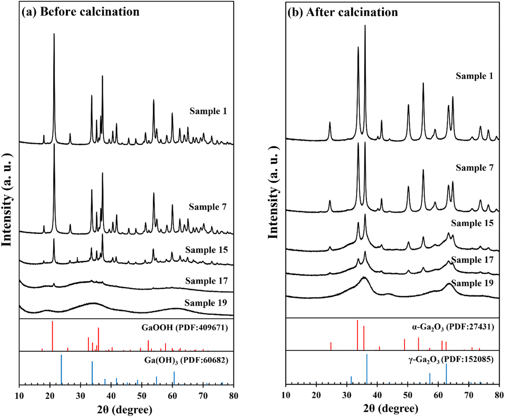 | ||
| Fig. 1 XRD patterns of samples (a) before and (b) after calcination. | ||
The XRD peaks of the α-phase were sharp enough to determine their crystallite sizes in the α/γ-Ga2O3 samples from the full width at half maximum (FWHM) of the (110) peak of the α-phase. The determined crystallite sizes are given in the bottom column of Table 1 and plotted against γ phase contents in Fig. 2. As seen in the figure, the size decreased almost linearly with increasing the γ phase content. On the other hand, the XRD peaks of the γ-phases were very broad indicating poor crystallization. This makes it impossible to determine the crystallite sizes of the γ-phase from the FWHM. It also makes it hard to determine the mixing ratio of α/γ phases (α/γ phase ratio) in the samples with the X-ray peak intensity ratio of both the phases. Therefore, the α/γ phase ratios represented as the γ contents in the α/γ-Ga2O3 samples were determined with the quantitative structural analysis using XANES and EXAFS as follows.
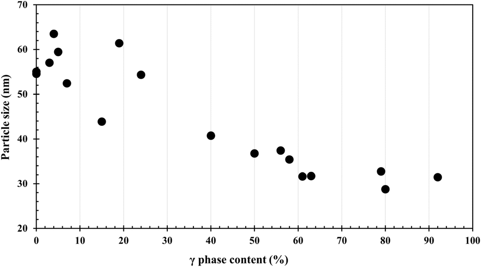 | ||
| Fig. 2 Changes of crystallite size determined by XRD analysis using the (110) diffraction of α-Ga2O3 with the contents of the γ phase. | ||
In Fig. 3(a) are compared three Ga K-edge XANES for α-Ga2O3, γ-Ga2O3 and sample 10 (α/γ-Ga2O3) with the inset of an enlarged one. Quantitative structural analysis using XANES is usually performed with microstructures that appeared at higher energy than the XANES absorption edge. As seen in Fig. 3(a), the difference in crystalline phases is apparent. Assuming the fine structures of α-Ga2O3 and γ-Ga2O3 were kept in α/γ-Ga2O3 samples, the fine structure of the α/γ-Ga2O3 sample was reproduced by the linear combination of those of α-Ga2O3 and γ-Ga2O3 with changing the combination ratio. The best fit result for sample 10 in Fig. 3(a) is given in Fig. 3(b) as the superposition of the observed one and reproduced one with a combination ratio of 60% α-Ga2O3 and 40% γ-Ga2O3. The reproduction by the linear combination was quite well with an error of a few %. Similar analysis was done for EXAFS as shown in Fig. 4. Fig. 4(a) is those for α-Ga2O3, γ-Ga2O3, and sample 10 and Fig. 4(b) compares the linear combination of EXAFS of α-Ga2O3 and γ-Ga2O3 with EXAFS of sample 10. The EXAFS analysis gave a quite similar α/γ mixing ratio to the XANES analysis. Thus, the determined mixing ratios of α-Ga2O3 and γ-Ga2O3 (α/γ mixing ratio) in all samples are given in the top column of Table 1 as the content of the γ-phase (%).
 | ||
| Fig. 3 (a) Ga K-edge XANES spectra of α-Ga2O3, γ-Ga2O3, and α/γ-Ga2O3 samples with enlarged views. (b) Least square fitting to the observed spectra with a linear combination of the spectra of α-Ga2O3 (60%) and γ-Ga2O3 (40%). | ||
 | ||
| Fig. 4 (Right) Ga K-edge EXAFS spectra of α-Ga2O3, γ-Ga2O3 and α/γ-Ga2O3 samples. (Left) Least square fitting to the observed spectra with a linear combination of the spectra of α-Ga2O3 (60%) and γ-Ga2O3 (40%). | ||
The results of BET specific surface area measurements are given Table 1 in the second line from the bottom, and are plotted against the γ-phase contents determined by the XANES analysis in Fig. 5. It is interesting to note that the specific surface area increases roughly linearly with the γ-phase content.
 | ||
| Fig. 5 Changes of BET specific surface area with γ phase contents. Lines are for guide to the eye. As seen in two dotted line lines, the surface areas are well represented with the linear combination of the surface areas of each phase. | ||
Fig. 6 shows the UV-vis spectra of α-Ga2O3, γ-Ga2O3 and α/γ-Ga2O3 samples. Although their band gap widths decreased with increasing γ-phase contents, no significant change appeared. This is consistent with the smooth changes of the BET surface area in Fig. 5.
 | ||
| Fig. 6 UV-vis spectra of α-Ga2O3, γ-Ga2O3 and α/γ-Ga2O3 samples with γ phase contents of 19% and 40%. | ||
Morphology
Fig. 7 shows the SEM images of (a) α-Ga2O3, (b) sample 10 (α/γ-Ga2O3) and (c) γ-Ga2O3. α-Ga2O3 consists of spheroid type particles uniformly with a length of nearly 1 μm. In the α/γ Ga2O3 samples, with increasing the γ-phase contents, their particle sizes gradually increased accompanying structure disorder or surface roughening. For higher γ-phase containing samples, the particle shape changed to polygons with random sizes. Fig. 8 shows the TEM images of (a) α-Ga2O3, (b) sample 10 (α/γ-Ga2O3) and (c) γ-Ga2O3 respectively corresponding to Fig. 7. The images clearly show that every particle observed in SEM consisted of small crystallites. In α-Ga2O3 (Fig. 8(a)) spheroid type crystallites with a length of several tens of nm were unidirectionally aligned, while those in γ-Ga2O3 (Fig. 8(c)) were polygons (or rather spherical) with sizes of less than 10 nm. The size of the spheroid type crystallite in the α phase is consistent with the particle sizes determined by the XRS analysis, ranging from 70 to 30 nm (see Table 1). The smaller crystallite size of the γ-phase well corresponds to its larger BET surface area. The α/γ-Ga2O3 sample (Fig. 8(b)) seems to be consisting of two different shaped particles of spheroids and polygons. To confirm this mixing of γ-phase and α-phase, the diffraction patterns of several localized areas in the particles of the α/γ-Ga2O3 sample were observed Fig. 8(d) and (e) are typical examples of the TEM image the particle and the diffraction pattern which consisted of diffraction spots assigned to (110) and (300) of the α-phase, and halo patterns to (331) and (731) of the γ-phase were appreciable. | ||
| Fig. 7 SEM images of (a) α-Ga2O3, (b) α/γ-Ga2O3 with a γ phase content of 40% and (c) γ-Ga2O3. | ||
 | ||
| Fig. 8 TEM images of (a) α-Ga2O3, (b) α/γ-Ga2O3 with a γ phase content of 40% and (c) γ-Ga2O3, and (d) the enlarged image of a particle appeared in (b) and (e) its electron diffraction pattern. | ||
These observations lead us to conclude that the α/γ-Ga2O3 samples consisted of two different types of fine particles; one is the spheroid type shaped and well crystallized α-Ga2O3 and the other is the polyhedron type and not well crystalized γ-Ga2O3. In addition, for the α/γ-Ga2O3 samples with lower γ-Ga2O3 contents, smaller polyhedrons of γ-Ga2O3 were embedded in the larger α-Ga2O3 spheroids, while for the higher γ-Ga2O3 contents the smaller α-Ga2O3 spheroids were surrounded by the polyhedrons of γ-Ga2O3.
Photocatalytic reduction of CO2 with water
All photocatalytic experiments have been performed over 5 hours to confirm that the production rates of H2, CO and O2 became constant.The dominant products of the photocatalytic reduction with water using the catalyst samples were H2, CO and O2. Their production rates satisfied the stoichiometry of ([H2] + [CO])/[O2] = 1, where [H2], [CO], and [O2] are the production rates of H2, CO, and O2, respectively. In Fig. 9 are plotted the production rates of H2 and CO for all catalyst samples against the contents of the γ-phase. The CO production rates increased by increasing the γ-phase content up to 40% and then decreased. Over 60% the CO production rates became small without clear correlation with the γ-phase contents. The H2 production rates were high for samples with lower γ-phase contents, while they were small for those samples with higher γ-phase contents over 60%. Both production rates seem differently depend on the γ-phase contents. However, as shown in Fig. 10 the ratios of the production rates of H2 and CO are clearly correlated with the γ-phase contents. Furthermore, the figure suggests that the reaction mechanism changes in the samples with γ-phase contents of below and above 60%. The reaction mechanism is discussed separately in the next section.
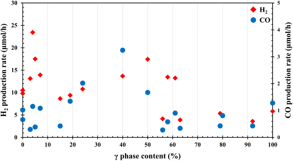 | ||
| Fig. 9 Production rates of H2 and CO plotted against the γ phase contents of the α/γ-Ga2O3 samples. | ||
 | ||
| Fig. 10 Ratios of the production rates of CO and H2 plotted against the γ phase contents of the α/γ-Ga2O3 samples. | ||
After the photocatalytic reduction, XRD and UV-vis of the samples showed no significant change except the new appearance of a small peak attributed to GaOOH in XRD.
Discussion
As seen in Fig. 5, BET surface areas of the α/γ Ga2O3 samples roughly linearly increased with the γ-phase contents and are well represented by the linear combination of those of the pure α-phase and pure γ-phase with the coefficient of each phase. This indicates that the BET surface areas of both the phases in the α/γ Ga2O3 samples were not influenced by the phase mixing. The observation of UV-vis also supports this. In addition, those of the α/γ Ga2O3 samples were dominated by the BET surface area of the γ-phase. This is because the γ-phase was not well crystallized or included various defects as indicated by its broad X-ray spectrum in Fig. 1 and the halo patterns of TEM diffraction in Fig. 8(e). In addition, the activity of the α/γ Ga2O3 samples with γ-phase contents more than 60% was weak similar to or even less than that of the pure γ-phase. The difference more clearly appeared in the ratio of the production rates of H2 and to CO (see Fig. 10), indicating that the mechanism of CO2 reduction was different between the samples containing the γ-phase less than 60% and higher ones.In the following, discussed is the mechanism of higher activity of the samples containing the γ-phase less than 60%. As seen in Fig. 9, H2 is mainly formed on the α-phase, while CO production increased by increasing the γ-phase content, reaching a maximum at about 40% γ-phase, and then decreasing despite the increase in the BET surface area. Considering redox type photocatalytic water splitting on the Ga2O3 catalyst indicated in previous studies, the present results strongly suggest that the H produced on the α-phase by the water splitting is used to reduce the CO2 adsorbed on the γ-phase, which has a large specific surface area.7–12 In the previous studies, we have confirmed the surface adsorption of CO2 as carbonate forms on Ga2O3.11,16,17
Based on this, we assume that some of the H produced on α- and γ-phases in the α/γ-Ga2O3 sample reduces CO2 adsorbed on either the α- or γ-phase and estimate how CO2 reduction rates change with the mixing ratio of α/γ-phases. Considering the BET surface change given in Fig. 5, we have employed an additional assumption that H production rates on the α-phase and the γ-phase do not change with the mixing. Then CO production rates in the α/γ-Ga2O3 samples can be calculated as follows. The reaction rates of hydrogen and CO on the α and γ phases are set to be v(H2)α and v(CO)α, and v(H2)γ and v(CO)γ, respectively, which are given as observed experimental values for the α and γ single phase samples. Then the CO generation on the mixed phase samples can be divided into the following three contributions; (1) CO generation caused by hydrogen generated on the α phase, (2) CO generation caused by hydrogen generated on the γ phase, and (3) CO generation on the γ phase caused by hydrogen generated on the α phase with the efficiency of k.
Since the hydrogen production rate on each phase in a α/γ-Ga2O3 sample should be proportional to the respective content of the α- and γ-phases, the CO production rates for the above three contributions are given as (1 − x)v(CO)α, xv(CO)γ, and k(1 − x)xv(H2)α, respectively. Here x is the content of the γ-phase. Then the total CO production rate in the α/γ-Ga2O3 samples is represented as
| v(CO)total = (1 − x)v(CO)α + xv(CO)γ + k (x − x2)(v(H2)α) | (1) |
 | ||
| Fig. 11 Comparison of CO production rates estimated by eqn (4) with the observed ones for the α/γ Ga2O3 samples with a γ phase content up to 50%. | ||
In the previous work, Aoki et al. indicated that photocatalytic water splitting on α-Ga2O3 proceeds through the following redox reactions of α-Ga2O3 and GaOOH.9,12
In water, the surface of α-Ga2O3 is oxyhydrided as,
| α-Ga2O3 + H2O → 2GaOOH | (2) |
and photo-irradiation reduces GaOOH producing H and O as,
| 2GaOOH + photon → Ga2O3 + 2H + O | (3) |
Thus produced H reduces CO2 as
| CO2 + 2H → CO + H2O | (4) |
In the present work, the formation of GaOOH was also observed in the XRD of the samples after use.
Considering all the above, the mechanism of the CO production on the mixed phase sample is schematically drawn as given in Fig. 12. From the morphology determined by XRD, SEM and TEM, the mixed phase samples consist of spheroid type α-Ga2O3 particles with smaller polyhedral type γ-Ga2O3 which was not well crystallized to show a large surface area and embedded in the α-Ga2O3 particles. Hydrogen is dominantly produced on the α-Ga2O3 particles thorough the redox of Ga2O3 and GaOOH and migrates to the γ-Ga2O3 particles embedded in the larger α-Ga2O3 particles to reduce CO2 adsorbed on it.
 | ||
| Fig. 12 Schematic drawing of the CO production mechanism on the α/γ-Ga2O3 samples and morphologies of α-Ga2O3, α/γ-Ga2O3 with the γ-concentration of 40% and γ-Ga2O3 (see text). | ||
In samples containing the γ-phase more than 60%, the particles of γ-Ga2O3 dominate to cover the minor α-Ga2O3 particles to inhibit oxyhydrization of α-Ga2O3. Consequently, hydrogen production is suppressed resulting in less CO production. Although the oxyhydrization of γ-Ga2O3would be possible, the product is very likely Ga(OH)3 which is the precursor of γ-Ga2O3 as seen in Fig. 1. The reduction of Ga(OH)3 by photons would be possible
| 2Ga(OH)3 + photon → Ga2O3 + 3H2O | (5) |
However, it requires major re-arrangement of Ga and O atoms, and the reaction would be harder to proceed. Accordingly, hydrogen production on the γ-phase is much less than that on the α-phase.
Conclusions
We have succeeded in synthesizing α/γ mixed-phase gallium oxides (α/γ-Ga2O3) with controlled α/γ mixing ratios by impregnation and calcination. The α/γ phase mixing ratios were determined quantitatively by XAFS structural analysis with the Ga K-edge. The prepared α/γ-Ga2O3 was used as the catalyst for the photoreduction of CO2 with water. Although the specific surface areas of α/γ-Ga2O3 nearly linearly increased from 38 m2 g−1 of the pure α-phase to 130 m2 g−1 for the pure γ-phase, they did not correlate well with the catalytic activity or the production rates of H2 and CO. Instead, the production rates of H2 and CO appreciably changed with the mixing ratio. The H2 formation dominated on the α-phase, while the CO production increased with increasing the γ-phase content and attained the maximum for a γ-content of 40%. Above 60% both the H2 and CO production rates decreased to the similar rates of the pure γ-phase much less than that of the pure α-phase. The ratio of the production rates of H2 and CO also increased with increasing the γ-content to the maximum at a γ-content of 40%. Above 40%, it decreased taking a minimum and then increased again suggesting a different mechanism for α-dominated and γ-dominated α/γ-Ga2O3.According to a reaction mechanism in the previous work, CO production in the photocatalytic CO2 reduction with water on α-Ga2O3 catalysts proceeds thorough the reaction of adsorbed CO2 with H produced by the water splitting. In analogy with this mechanism, we have assumed that some of the H produced on the α-phase reduces CO2 adsorbed on the γ-phase and made a kinetic equation to give the CO production rate taking into account the H production rate on the α phase and CO production rates with the reaction of H produced on the α-phase and CO2 adsorbed on the γ phase, and the contents of both the phases. The equation fits well to the observed relation of the CO production rates with the α/γ mixing ratio up to a γ content of 50%. This confirms the reaction mechanism that H produced on the α-phase reduces CO2 adsorbed on the γ-phase.
TEM observations of α/γ-Ga2O3 revealed that the spheroid type α-Ga2O3 particles were coexisting with smaller polyhedral type γ-Ga2O3 which was not well crystalized to show a large surface area. In α/γ-Ga2O3 containing the γ-phase less than 40%, γ-Ga2O3 particles were embedded in the α-Ga2O3 particles, while in α/γ-Ga2O3 containing the γ-phase more than 60% γ-Ga2O3 particles covered α-Ga2O3 particles. These observations well correspond to the above reaction mechanism below 50% and similar activities with the γ-phase for above 60%.
Data availability
Raw data were generated at Osaka Metropolitan University. Derived data supporting the findings of this study are available from Tomoko Yoshida on request.Conflicts of interest
The authors declare no conflict of interest.References
- Z. Huang, K. Teramura, H. Asakura, S. Hosokawa and T. Tanaka, Curr. Opin. Chem. Eng., 2018, 20, 114 CrossRef
.
- M. Yamamoto, T. Yoshida, N. Yamamoto, T. Nomoto, Y. Yamamoto, S. Yagi and H. Yoshida, J. Mater. Chem. A, 2015, 3, 16810 RSC
- N. Yamamoto, T. Yoshida, S. Yagi, Z. Like, T. Mizutani, S. Ogawa, H. Nameki and H. Yoshida, e-J. Surf. Sci. Nanotechnol., 2014, 12, 263 CrossRef CAS
- Y. Pan, Z. Sun, H. Cong, Y. Men, S. Xin, J. Song and S. Yu, Nano Res., 2016, 9, 1689 CrossRef CAS
- S. Kikkawa, K. Teramura, H. Asakura, S. Hosokawa and T. Tanaka, J. Phys. Chem. C, 2018, 122, 21132 CrossRef CAS
- H. Yoon, J. Yang, S. Park, C. Rhee and Y. Sohn, Appl. Surf. Sci., 2021, 536, 147753 CrossRef CAS
- P. Chen, K. Li, B. Lei, L. Chen, W. Cui, Y. Sun, W. Zhang, Y. Zhou and F. Dong, ACS Appl. Mater. Interfaces, 2021, 13, 50975 CrossRef CAS PubMed
- K. Sonoda, M. Yamamoto, T. Tanabe and T. Yoshida, Appl. Surf. Sci., 2021, 542, 148680 CrossRef CAS
- T. Aoki, M. Yamamoto, T. Tanabe and T. Yoshida, New J. Chem., 2022, 46, 3207 RSC
- M. Akatsuka, Y. Kawaguchi, R. Itoh, A. Ozawa, M. Yamamoto, T. Tanabe and T. Yoshida, Appl. Catal., B, 2020, 262, 118247 CrossRef CAS
- Y. Kawaguchi, M. Yamamoto, A. Ozawa, Y. Kato and T. Yoshida, Surf. Interface Anal., 2019, 51, 79 CrossRef CAS
- T. Aoki, K. Ichikawa, K. Sonoda, M. Yamamoto, T. Tanabe and T. Yoshida, RSC Adv., 2022, 12, 7164 RSC
- L. Li, W. Wei and M. Behrens, Solid State Sci., 2012, 14, 971 CrossRef CAS
- T. Sato and T. Nakamura, J. Chem. Technol. Biotechnol., 1982, 32, 433 CrossRef
- Y. Hou, L. Wu, X. Wang, Z. Ding, Z. Li and X. Fu, J. Catal., 2007, 250, 12 CrossRef CAS
- M. Yamamoto, S. Yagi and T. Yoshida, Catal. Today, 2018, 303, 334 CrossRef CAS
- M. Yamamoto, T. Yoshida, N. Yamamoto, H. Yoshida and S. Yagi, e-J. Surf. Sci. Nanotechnol., 2014, 12, 299 CrossRef CAS
| This journal is © The Royal Society of Chemistry 2025 |