
 Open Access Article
 This Open Access Article is licensed under a Creative Commons Attribution-Non Commercial 3.0 Unported Licence
High-conductivity, low-temperature sintering-compatible NASICON solid electrolyte for enhanced compositing with hard carbon electrode in all-solid-state batteries†
Bowei
Xun
 a,
Jian
Wang
a,
Yukio
Sato
b,
George
Hasegawa
c,
Hirofumi
Akamatsu
a and
Katsuro
Hayashi
*a
a,
Jian
Wang
a,
Yukio
Sato
b,
George
Hasegawa
c,
Hirofumi
Akamatsu
a and
Katsuro
Hayashi
*a
aDepartment of Applied Chemistry, Graduate School of Engineering, Kyushu University, 744 Motooka, Nishi-ku, Fukuoka 819-0395, Japan. E-mail: k.hayashi@cstf.kyushu-u.ac.jp
bResearch and Education Institute for Semiconductors, Informatics, Kumamoto University, 2-39-1 Kurokami, Chuo-ku, Kumamoto 860-8555, Japan
cInstitute of Materials and Systems for Sustainability, Nagoya University, Furo-cho, Chikusa-ku, Nagoya 464-8601, Japan
First published on 23rd December 2024
Abstract
Oxide-based all-solid-state sodium-ion batteries present a safer, more robust and more sustainable alternative to lithium-ion batteries, though fabrication challenges persist, particularly during co-sintering. In this study, we demonstrate that by adding sodium borate-based sintering aids to highly conductive Na3Zr2(SiO4)2(PO4) (NZSP)-based materials, both a lower sintering temperature and high ionic conductivity can be achieved. Specifically, the mixture of Na2CO3 and B2O3 as a sintering aid is crucial, and samples sintered at 900 °C with a Na3.4Zr1.95Al0.05(SiO4)2.35(PO4)0.65 composition exhibits a Na+ ion conductivity exceeding 4 × 10⁻³ S cm−1 at room temperature. These materials are also compatible with co-sintering alongside hard carbon anode materials. The all-solid-state cell, featuring a composite electrode of spherical hard carbon particles and optimized NZSP-based electrolytes, demonstrated stable charge–discharge performance at room temperature, retaining a capacity of 140–220 mA h g−1 across 80 cycles.
Oxide-based all-solid-state sodium-ion batteries (Na ASSBs) are regarded as a safer, more robust, and more sustainable alternative to traditional lithium-ion batteries (LIBs). However, challenges persist in their fabrication, particularly in the co-sintering of materials such as electrolytes, electrode active materials, and other components.1–3 NASICON-type Na3Zr2(SiO4)2(PO4) (NZSP)-based materials are promising candidates for solid electrolytes due to their high ionic conductivity and moderate sintering temperatures. Through various chemical modifications, the ionic conductivity of NZSP-based electrolytes, which are sintered at around 1250 °C, can reach levels comparable to sulfide-based electrolytes.4–7 (For summary of reported data, see ESI Table S1.†) Recently, we demonstrated that optimizing the Si/P ratio and introducing a small amount of Al dopant resulted in a record conductivity of 6 × 10⁻³ S cm−1 at room temperature (RT).8
To address the need for lower sintering temperatures, liquid-phase sintering aids have been investigated.9–17 For example, Na3BO3 can lower sintering temperatures to 700–900 °C (ref. 10 and 14) while maintaining an RT conductivity more than 1 × 10⁻³ S cm−1 for a material sintered at 900 °C.14 (For sintering temperature-conductivity trend, see ESI Fig. S1.†) This study focuses on further enhancing the conductivity by employing the chemically-modified NZSPs combined with sodium borate-based sintering aids. Our findings show that a total conductivity of >4 × 10⁻³ S cm−1 at RT is achievable at a reduced sintering temperature of 900 °C using the optimal chemical composition and preparation method.
The study also incorporates hard carbon (HC) as an electrode active material in a composite electrode for Na ASSBs, highlighting the compatibility of high-conductivity, low-sintering-temperature materials. HCs, or non-graphitizing carbons, are widely recognized as suitable sodium-insertion negative electrode materials for liquid-electrolyte-based sodium-ion batteries.18–21 Well-engineered HCs can deliver even higher electrochemical capacities21,22 than the theoretical value for lithium in graphite insertion compound (Li-GIC, 372 mA h g−1),23 with a smaller volume expansion upon full insertion/deinsertion (13.2% for C to LiC6).24 The latter property may be particularly beneficial for ASSB systems, which often consists of materials with lower mechanical compliance.25 However, despite the potential of HCs, their integration via sintering has not been extensively explored, likely due to the challenging reactivity between oxide and carbon materials. This study successfully demonstrates the compositing of NZSP-based electrolytes with HC through atmospheric pressure sintering at 900 °C, achieving good electrochemical performance at RT without the need for organic or liquid agents.
In our previous study,8 ceramic samples with the compositions Na3Zr2(SiO4)2(PO4) (NZSP), Na3.35Zr2(SiO4)2.35(PO4)0.65 (NZS2.35P), and Na3.4Zr1.95Al0.05(SiO4)2.35(PO4)0.65 (NZAS2.35P) were prepared by sintering at 1270 °C in air. Among these, the Al-doped NZAS2.35P exhibited the highest ionic conductivity. In this study, a 10 wt% mixture of Na2CO3 and B2O3 in a 2![[thin space (1/6-em)]](https://www.rsc.org/images/entities/char_2009.gif) :1 molar ratio (abbreviated as 10N2B) was added into the three base compositions, and dense ceramics were obtained by sintering at 900 °C for 12 h in air. Additionally, NZAS2.35P samples with varying amounts (y wt%) of N2B, ranging from 0 to 20 wt% (NZAS2.35P-yN2B), as well as samples containing 10 wt% Na2B4O7 (NZAS2.35P-10Na2B4O7), were prepared for comparison. X-ray diffractometry (XRD) confirmed that these samples predominantly consist of NASICON-type crystals with a monoclinic space group C2/c, along with minor secondary phases of ZrO2 (ESI Fig. S2†). Rietveld analysis was performed on the XRD patterns of NZSP-10N2B and NZAS2.35P-10N2B (ESI Fig. S3, Tables S2 and S3†), confirming that crystallographic features of NASICON phases inherit those of NZSP and NZAS2.35P in our previous study.8 The amount of ZrO2 in these samples was typically ∼5%.
:1 molar ratio (abbreviated as 10N2B) was added into the three base compositions, and dense ceramics were obtained by sintering at 900 °C for 12 h in air. Additionally, NZAS2.35P samples with varying amounts (y wt%) of N2B, ranging from 0 to 20 wt% (NZAS2.35P-yN2B), as well as samples containing 10 wt% Na2B4O7 (NZAS2.35P-10Na2B4O7), were prepared for comparison. X-ray diffractometry (XRD) confirmed that these samples predominantly consist of NASICON-type crystals with a monoclinic space group C2/c, along with minor secondary phases of ZrO2 (ESI Fig. S2†). Rietveld analysis was performed on the XRD patterns of NZSP-10N2B and NZAS2.35P-10N2B (ESI Fig. S3, Tables S2 and S3†), confirming that crystallographic features of NASICON phases inherit those of NZSP and NZAS2.35P in our previous study.8 The amount of ZrO2 in these samples was typically ∼5%.
Fig. 1 presents the relative densities of the samples, along with scanning electron microscopy (SEM) images of the sintered surfaces for selected samples. The relative density peaks at y = 10 wt%, indicating that this is the optimal additive amount for densification. The composition of the NZSP-based materials has a minor impact on densification. Without the use of sintering aids (Fig. 1b), numerous voids are present, and crystal growth is limited. The samples with sintering aids (Fig. 1c–e) show well-densified microstructures with enhanced grain growth and very few pores (average grain size data, see ESI Fig. S4†). There is a distinct difference in microstructure between those with Na2CO3 and B2O3 added separately (Fig. 1c and d) and that with Na2B4O7 added directly (Fig. 1e). The former samples exhibit a macroscopically uniform appearance, while the latter display dark-contrast aggregates, suggesting they are amorphous aggregates composed of lighter elements. These aggregates are enriched with the Na2B4O7 component, indicating poor wetting with the host crystalline phase. In the case of the separate NB2 addition, CO2 is expected to be released during sintering, resulting in a composition similar to Na2B4O7; however, the microstructure differs significantly. This suggests that the separate addition and in situ reaction are significant for enhancing wetting properties.
 | ||
| Fig. 1 Sinterability and microstructure of NZSP-based electrolytes sintered at 900 °C for 12 h in air. (a) The relative density of the NZSP, NZS2.35P, and NZAS2.35P ceramics, as the function of the wt% of 2Na2CO3 + B2O3 (N2B) additive, and NZAS2.35P-10Na2B4O7. The relative density is based on the theoretical value (3.27 g cm−3) for NZSP for simplicity. (b–e) Surface SEM images for NZAS2.35P (b) without the sintering aid (average grain size of <0.3 μm), (c) with 10 wt% N2B (0.7 μm), (d) with 10 wt% NB2(0.6 μm), and (e) with 10 wt% Na2B4O7 (0.5 μm). | ||
Electrical conductivity in the prepared samples was measured using electrochemical impedance spectroscopy (EIS). Nyquist plots for NZSP-10N2B, NZS2.35P-10N2B, and NZAS2.35P-10N2B at −40 °C were fitted by an equivalent circuit model, identifying bulk and grain boundary resistances (Fig. 2a). Notably, the grain boundary resistance in NZAS2.35P-10N2B decreased with increasing temperature, becoming negligible at 25 °C (Fig. 2b). DC polarization measurements at 25 °C (ESI Fig. S5†) revealed very low partial electronic conductivities. For instance, the electronic conductivity in NZAS2.35P-10N2B was approximately five orders of magnitude lower than the total conductivity, confirming its pure Na+ ion conducting nature.
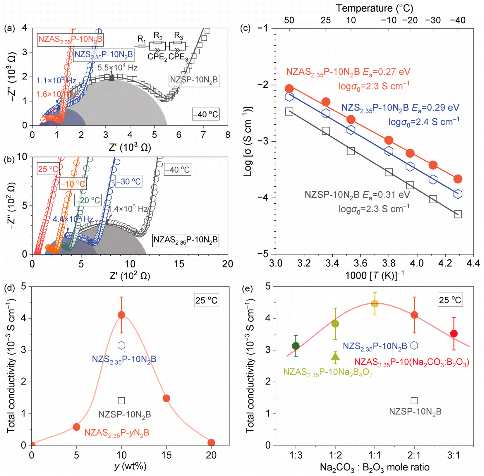 | ||
| Fig. 2 Ionic conductivity measured by EIS. (a) Nyquist plots for NZSP-10N2B (black), NZS2.35P-10N2B (blue), and NZAS2.35P-10N2B (red) at −40 °C (open symbols), with fitting curves (solid lines) by equivalent circuit modeling (inset). The semicircles corresponding to the grain boundary (parallel R2-CPE2) components are shaded. (b) Nyquist plots of the total conductivity measured for NZAS2.35P-10N2B at temperatures ranging from −40 to 25 °C. (c) Arrhenius plots of the total conductivities at temperatures ranging from −40 to 50 °C for the samples in (a). (d) Total conductivity of NZSP-10N2B, NZS2.35P-10N2B, and NZAS2.35P-yN2B (y = 0–20) at 25 °C (e) total conductivity of NZSP-10N2B (open square), NZS2.35P-10N2B (open hexagon), NZAS2.35P added with different ratios of Na2CO3 and B2O3 from N3B to NB3 (filled circles), and NZAS2.35P added with Na2B2O7 (filled triangle) at 25 °C. | ||
The conductivity (σ)–temperature (T) relationship followed Arrhenius behavior with activation energies (Ea) ranging from 0.27 to 0.31 eV (Fig. 2c). The value of Ea and the pre-exponential factor (σ0) indicated in the figure were estimated from the equation σT = σ0exp(−Ea/kBT), where kB is the Boltzmann constant. NZAS2.35P-based samples with varying N2B content exhibited a peak conductivity of 4.1 × 10⁻³ S cm−1 at 10 wt% N2B (Fig. 2d), while conductivity significantly dropped to 4.2 × 10⁻⁶ S cm−1 without the sintering aid. All NZAS2.35P-based samples containing 10 wt% of additives with different Na2CO3 and B2O3 ratios showed improved conductivity, with a maximum value of 4.5 × 10⁻³ S cm−1 for the 1:1 ratio (Fig. 2e). It is noted that the conductivity in NZAS2.35P-10Na2B4O7 was lower than that of NZAS2.35P-10NB2. Thus, a homogeneous microstructure as well as grain growth are essential for reducing grain boundary resistivity. Additionally, the base chemical composition also plays a decisive role in conductivity, impacting both bulk and grain boundary properties as discussed in our previous paper.8
A spherical-shaped hard carbon (hard carbon sphere, HCS) powder with particle sizes ranging from 0.4 to 0.6 μm was prepared from a hydrothermally synthesized resorcinol-formaldehyde (RF)-gel precursor, followed by a calcination in an N2 atmosphere.26 This electrode material delivered 272 mA h g−1 at room temperature and at the rate of 100 mA g−1 in a liquid electrolyte cell (ESI Fig. S6†). The HCS powder is investigated as a potential negative electrode material for in an ASSB. A composite electrode layer, consisting of HCS and NZAS2.35P-10N2B with weight ratio of 3:4, corresponding to a volume ratio of approximately 6:5, was formed by spin coating onto an NZAS2.35P-10N2B ceramic substrate and subsequently heated at 900 °C in an N2 atmosphere to consolidate the coating layer. After sintering, the thick film was mechanically strong enough to adhere to the electrolyte substrate (ESI Fig. S7†). Preservation of the NASICON phase was confirmed by XRD (ESI Fig. S2†).
Fig. 3 presents the scanning transmission electron microscopy (STEM) and energy-dispersive X-ray spectroscopy (EDS) analysis of cross-section of HCS-NZAS2.35P-10N2B|NZAS2.35P-10N2B junction. The composite electrode layer, approximately 4–5 μm in thickness, exhibit a partially aggregated distribution of HCS with NZSP-based electrolyte and voids. The interfacial regions are well densified, forming close and intimate junctions. Areas with electrolyte particle aggregation are also densified, while voids are observed in regions lacking sufficient electrolyte, supporting that the NZAS2.35P-10N2B components serve as a ‘binder’ for the HCS.
 | ||
| Fig. 3 STEM analyses for the cross section of HCS-NAS2.35P-10N2B composite electrode (upper side) on NAS2.35P-10N2B ceramic substrate (lower side). (a) High-angle annular dark-field (HAADF) image; and (b–h) elemental distribution maps obtained by EDS for (b) composite of C (red), Na (green) and O (blue), (c) C, (d) Na, (e) Al, (f) Zr, (g) Zr, and (h) O K-line signals. | ||
The EDS maps (Fig. 3b–h) reveal that the region surrounding HCS enriched with Na and O components. This material appears to have excellent wettability with the HCS and is likely attributed to the solidified sodium borate-based phase, where B atoms are undetectable by EDS. Closer observation reveals that the interfacial layer surrounding the HCS contains not only Si and Al but also Zr, although P could not be sufficiently distinguished from Zr by EDS (ESI Fig. S8†). This suggests a process involving the dissolution and precipitation of NZAS2.35P components via a liquid phase during sintering. In contrast, Al is preferentially segregated at the grain boundaries and triple junctions of the NZAS2.35P crystals, giving these regions a different chemical identity from the that around the HCS (ESI Fig. S8†). This leads to the assumption that, as the sintering progresses, the residual sodium borate-based liquid phase are expelled from the electrolyte region and accumulated around the HCS. Resultant Na-rich interfacial layer is expected to mediate Na diffusion during battery operation.
The electrochemical properties of the composite electrode formed on the electrolyte substrate were investigated in a half-cell configuration with a metallic Na counter electrode. Fig. 4a presents the charge and discharge curves measured at a current density of 20 mA g−1. The curves exhibit a characteristic sloping region above ∼0.1 V and plateau region between 0.01 and 0.1 V, similar to those observed in liquid electrolyte systems.20,22,23,27 The first sodiation and desodiation capacities are 330 and 220 mA h g−1, respectively, based on the weight of HCS, with an initial coulombic efficiency of 66%. The observed irreversibility during the initial cycles in the solid-state system remains a topic for future investigation. In subsequent cycles, the discharge capacity gradually decreases to 140 mA h g−1, while the coulombic efficiency improves to over 99% (Fig. 4b). The EIS before and after 80 cycles showed no significant changes in resistance associated with the electrolyte–electrode interface, and the low-frequency response, related to diffusion in the composite electrode, exhibited a small decrease in capacitance and resistance, likely relating to the change in electrochemical properties of HCSs (ESI Fig. S9†). Fig. 4c shows the results of rate-dependent capacity measurements, the cell delivers 140 mA h g−1 at a high current density of 200 mA g−1. When the current density is reduced back to 10 mA g−1, the cell recovers a capacity of 180 mA h g−1, overall substantiating stable interface formation and efficient Na+ ion transport between the composite electrode and the electrolyte.
 | ||
| Fig. 4 Electrochemical properties in a half cell of Na|NZAS2.35P-10N2B|HCS-NZAS2.35P-10N2B composite electrode at 25 °C. (a) Charge–discharge curves of selected cycles measured at a current density of 6 μA cm−2, corresponding to 20 mA g−1, in cut-off voltage ranges from 0.01 to 2.5 V; (b) electrochemical capacities and coulombic efficiency for discharge cycles; (c) rate performances and coulombic efficiency at various current densities ranging from 10 to 200 mA g−1. | ||
Conclusions
In summary, we demonstrated that the addition of (optimally 10 wt%) mixture of Na2CO3 and B2O3 to NASICON-based materials may produce highly conductive Na+ ion solid electrolyte, achieving a maximum conductivity of 4.5 × 10⁻³ S cm−1 at 25 °C, with a reduced sintering temperature of 900 °C. A composite electrode, consisting of hard carbon spheres (HCS) and NZAS2.35P-10N2B, was fabricated by consolidating the mixture through heating at 900 °C in an N2 atmosphere. Electrochemical testing revealed initial charge and discharge capacities of 330 and 220 mA h g−1, respectively, followed by a gradual decrease in capacities to 140 mA h g−1 and improved coulombic efficiency over successive cycles. These results highlight the successful electrochemically active integration of HCS with a NZSP-based electrolyte without the need for organic or liquid additives, representing an advancement toward the development of oxide-based Na ASSB.Data availability
The data supporting this article have been included as part of the ESI.† The datasets generated and/or analyzed during the current study are available from the corresponding author upon reasonable request.Author contributions
B. Xun: preparation for materials, collecting data, investigation, formal analysis, writing original manuscript; J. Wang: investigation, review; Y. Sato: TEM analysis, review; G. Hasegawa: conceptualization, investigation, review; H. Akamatsu: review, funding acquisition; K. Hayashi: conceptualization, project administration, supervision, investigation, writing, review & editing, funding acquisition.Conflicts of interest
The authors declare no competing financial interest.Acknowledgements
This work was supported by Grant-in-Aid for Green Technologies of Excellence (GteX) (no. JPMJGX23S4) from Japan Science and Technology Agency (JST), Japan. The STEM analyses were carried out at Engineering Research Equipment Center, Kumamoto University. We thank Ziyue Zhang for experimental support. B. X. thanks the CSC scholarship sponsored by the China Scholarship Council (CSC).References
- G. Hasegawa and K. Hayashi, APL Energy, 2023, 1, 020902 CrossRef.
- D. Kutsuzawa, T. Kobayashi and S. Komiya, ACS Appl. Energy Mater., 2022, 5, 4025–4028 CrossRef CAS.
- D. Kutsuzawa and T. Kobayashi, Batteries Supercaps., 2023, 6, e202300075 CrossRef CAS.
- J. Yang, G. Liu, M. Avdeev, H. Wan, F. Han, L. Shen, Z. Zou, S. Shi, Y.-S. Hu and C. Wang, ACS Energy Lett., 2020, 5, 2835–2841 CrossRef CAS.
- Q. Ma, C.-L. Tsai, X.-K. Wei, M. Heggen, F. Tietz and J. T. S. Irvine, J. Mater. Chem. A, 2019, 7, 7766–7776 RSC.
- Y. B. Rao, K. K. Bharathi and L. N. Patro, Solid State Ionics, 2021, 366–367, 115671 CrossRef CAS.
- S. Ohno, A. Banik, G. F. Dewald, M. A. Kraft, T. Krauskopf, N. Minafra, P. Till, M. Weiss and W. G. Zeier, Prog. Energy, 2020, 2, 022001 CrossRef.
- B. Xun, J. Wang, Y. Sato, S. Jia, S. Ohno, H. Akamatsu and K. Hayashi, Adv. Energy Mater., 2024, 2402891 CrossRef.
- H. Wang, G. Zhao, S. Wang, D. Liu, Z. Mei, Q. An, J. Jiang and H. Guo, Nanoscale, 2022, 14, 823–832 RSC.
- K. Suzuki, K. Noi, A. Hayashi and M. Tatsumisago, Scr. Mater., 2018, 145, 67–70 CrossRef CAS.
- Y. Zhao, C. Wang, Y. Dai and H. Jin, Nano Energy, 2021, 88, 106293 CrossRef CAS.
- B. Santhoshkumar, M. B. Choudhary, A. K. Bera, S. M. Yusuf, M. Ghosh and B. Pahari, J. Am. Ceram. Soc., 2022, 105, 5011–5019 CrossRef CAS.
- J. A. S. Oh, L. He, A. Plewa, M. Morita, Y. Zhao, T. Sakamoto, X. Song, W. Zhai, K. Zeng and L. Lu, ACS Appl. Mater. Interfaces, 2019, 11, 40125–40133 CrossRef CAS.
- K. Noi, K. Suzuki, N. Tanibata, A. Hayashi and M. Tatsumisago, J. Am. Ceram. Soc., 2018, 101, 1255–1265 CrossRef CAS.
- Y. Ji, T. Honma and T. Komatsu, Materials, 2021, 14, 3790 CrossRef CAS PubMed.
- H. Wang, K. Okubo, M. Inada, G. Hasegawa, N. Enomoto and K. Hayashi, Solid State Ionics, 2018, 322, 54–60 CrossRef CAS.
- K. Okubo, H. Wang, K. Hayashi, M. Inada, N. Enomoto, G. Hasegawa, T. Osawa and H. Takamura, Electrochim. Acta, 2018, 278, 176–181 CrossRef CAS.
- M. Zhang, Y. Li, F. Wu, Y. Bai and C. Wu, Nano Energy, 2021, 82, 105738 CrossRef CAS.
- B. Xiao, T. Rojo and X. Li, ChemSusChem, 2019, 12, 133–144 CrossRef CAS PubMed.
- Y. Aniskevich, J. H. Yu, J.-Y. Kim, S. Komaba and S.-T. Myung, Adv. Energy Mater., 2024, 14, 2304300 CrossRef CAS.
- X. Dou, I. Hasa, D. Saurel, C. Vaalma, L. Wu, D. Buchholz, D. Bresser, S. Komaba and S. Passerini, Mater. Today, 2019, 23, 87–104 CrossRef CAS.
- A. Kamiyama, K. Kubota, D. Igarashi, Y. Youn, Y. Tateyama, H. Ando, K. Gotoh and S. Komaba, Angew. Chem., Int. Ed., 2021, 60, 5114–5120 CrossRef CAS PubMed.
- S. Alvin, H. S. Cahyadi, J. Hwang, W. Chang, S. K. Kwak and J. Kim, Adv. Energy Mater., 2020, 10, 2000283 CrossRef CAS.
- S. Schweidler, L. de Biasi, A. Schiele, P. Hartmann, T. Brezesinski and J. Janek, J. Phys. Chem. C, 2018, 122, 8829–8835 CrossRef CAS.
- J. A. S. Oh, G. Deysher, P. Ridley, Y.-T. Chen, D. Cheng, A. Cronk, S.-Y. Ham, D. H. S. Tan, J. Jang, L. H. B. Nguyen and Y. S. Meng, Adv. Energy Mater., 2023, 13, 2300776 CrossRef CAS.
- J. Liu, S. Z. Qiao, H. Liu, J. Chen, A. Orpe, D. Zhao and G. Q. (Max) Lu, Angew. Chem., Int. Ed., 2011, 50, 5947–5951 CrossRef CAS PubMed.
- Y. Morikawa, S. Nishimura, R. Hashimoto, M. Ohnuma and A. Yamada, Adv. Energy Mater., 2020, 10, 1903176 CrossRef CAS.
Footnote |
| † Electronic supplementary information (ESI) available: Detailed experimental methods; summary of literature about NZSP-based ceramics with sintering-aid; XRD; Rietveld analysis; particle size in sinters; DC polarization measurement; charge–discharge curves of HCS electrode in a liquid electrolyte cell; Scotch tape test; STEM-EDS analysis; EIS. See DOI: https://doi.org/10.1039/d4ta07954j |
| This journal is © The Royal Society of Chemistry 2025 |