
 Open Access Article
 This Open Access Article is licensed under a
 Creative Commons Attribution 3.0 Unported Licence
Micropores can enhance the intrinsic fracture energy of hydrogels†
Puyu
Cao
 a,
Bin
Chen
*ab,
Yi
Cao
cd and
Huajian
Gao
e
a,
Bin
Chen
*ab,
Yi
Cao
cd and
Huajian
Gao
e
aDepartment of Engineering Mechanics, Zhejiang University, Hangzhou, People's Republic of China. E-mail: chenb6@zju.edu.cn
bKey Laboratory of Soft Machines and Smart Devices of Zhejiang Province, Hangzhou, People's Republic of China
cSchool of Physics, Nanjing University, Nanjing, China
dCollaborative Innovation Center of Atmospheric Environment and Equipment Technology, Jiangsu Key Laboratory of Atmospheric Environment Monitoring and Pollution Control, School of Environmental Science and Engineering, Nanjing University of Information Science & Technology, Nanjing 210044, P. R. China
eMechano-X Institute, Applied Mechanics Laboratory, Department of Engineering Mechanics, Tsinghua University, Beijing 100084, China
First published on 24th February 2025
Abstract
Hydrogels, a class of soft materials composed of a polymer chain network, are widely known to be prone to fatigue failure. To understand the underlying mechanisms, we simulate polymer scission and fatigue initiation in the vicinity of a crack tip within a two-dimensional polymer network. For a network without pores, our findings reveal that polymer scission can occur across multiple layers of chains, rather than just a single layer as assumed in the classical Lake–Thomas theory, consistent with previous studies. In contrast, for a network with a high density of micropores, our results demonstrate that the pores can substantially enhance the intrinsic fracture energy of the network in direct proportion to the pore size. This enhancement is attributed to pore–pore interactions, which lead to a relatively uniform distribution of cohesive energy ahead of the crack tip. Our model suggests that incorporating micropores could be a promising strategy for improving the intrinsic fracture energy of hydrogels and that natural porous tissues may have evolved to achieve enhanced fatigue resistance.
Introduction
In recent years, synthetic hydrogels have undergone significant advancements and are increasingly utilized across various fields such as tissue engineering, agriculture, drug delivery, soft robotics, and flexible devices, among others.1–4 Many of these applications require hydrogels to withstand cyclic loads, including repetitive loading on hydrogel-based biomimetic skins5 and cartilage,6 even though hydrogels are known to be susceptible to fatigue failure.7 To tackle this challenge, a number of hydrogels with elevated fatigue thresholds have been developed using various strategies.8–10The fatigue threshold of hydrogels is primarily attributed to their intrinsic fracture energy,11,12 which corresponds to the limit below which fatigue cracks do not propagate. Generally, viscosity or dynamics are not considered when calculating such a limit. The fatigue threshold has traditionally been evaluated11,13–17 using the Lake–Thomas theory,18 which focuses on the breakage of a single layer of polymer chains across the crack plane (Fig. 1a) without triggering inelastic deformation in the bulk. The thickness of a chain layer in its unstrained state can be approximated, for instance, by the equilibrium separation between two ends of an individual polymer chain in the freely-jointed chain model. Theoretical predictions have demonstrated good agreement with experimental findings across various polymeric materials, such as PAAm–Ca–alginate,19,20 PAAm–PAMPS,13 and PAAm–polyvinyl alcohol.11 Nevertheless, a source of uncertainty arises from estimating the thickness of the energy-dissipating layer, and open questions remain regarding why chain scission appears confined to a single layer rather than involving multiple layers of chains.19
 | ||
| Fig. 1 Classical Lake–Thomas theory and evidence for the existence of micropores in hydrogels. (a) A schematic illustration of the Lake–Thomas theory, which assumes that the intrinsic fracture energy of a polymer is due to the scission of a layer of polymer chains along the prospective crack plane. (b) An SEM image of polyacrylamide hydrogel showing small pores with diameters of approximately 2 μm. (c) Verification of pore size through the free diffusion of beads with diameters of approximately 2 μm. | ||
High-density pores are often introduced in hydrogels through phase separation during synthesis.21 SEM images of polyacrylamide hydrogels reveal a multitude of micropores with diameters of approximately 2 μm (Fig. 1b), through which microbeads can diffuse (Fig. 1c). The average pore size,22 pore size distribution, and interconnections between pores are crucial aspects of a hydrogel matrix. Notably, in freeze-dried hydrogels derived from silk fibroin solutions, pore sizes diminish with increasing silk fibroin concentration and decrease with rising temperature at a constant silk fibroin concentration.23 Hydrogels freeze-dried with Ca2+ exhibit larger pore sizes compared to those without Ca2+ ions in the silk fibroin aqueous solutions.24 Various technologies, including solvent casting particle leaching,25 freeze-drying,26 gas foaming,27 and electrospinning,28 have been deployed to regulate the microarchitectural features of pores in hydrogels and facilitate the creation of functional hydrogels that mimic native tissue structures, thereby enhancing cell viability,29 proliferation30 and migration.31
This study aims to investigate the effect of micropores on the intrinsic fracture energy of the polymer network in a hydrogel. We begin by validating the Lake–Thomas theory18 using a two-dimensional (2D) chain network model with a pre-existing crack. Our results from the polymer network model indicate that multiple layers of chains are involved in crack advance at the fatigue threshold, thereby challenging the assumption in the Lake–Thomas theory. Nevertheless, our simulation results are in agreement with the commonly held view in the literature that the intrinsic fracture energy of a polymer network generally scales with and is thus limited by the initial length of individual chains. To determine whether it is possible to overcome this size limitation imposed by the initial chain length, we subsequently simulate the polymer chain scission and fatigue initiation in the vicinity of a crack in a 2D soft material containing a high density of micropores by integrating the finite element method (FEM) and the polymer network model at the crack tip. Our findings reveal that the presence of pores alters the stress distribution within the material, leading to a significant enhancement of the intrinsic fracture energy, which can scale with and be substantially enhanced by the pore size under certain conditions. Our study provides an integrated modeling framework for understanding the intrinsic fracture energy of both non-porous and porous hydrogels, with results highlighting the potential for designing hydrogels with specific microarchitectural features to improve the intrinsic fracture energy.
Validation of the Lake–Thomas theory
Several polymer chain network models were recently developed32–35 to investigate the mechanical behaviors of polymeric materials. To validate the classical Lake–Thomas theory, we constructed a 2D polymer chain network in COMSOL, which is convenient to use and differs from most of the previous polymer chain network models. Our chain network is composed of truss elements representing individual polymer chains, as well as solid elements for sustaining 2D hydrostatic pressure. Within the network, polymer chains are periodically distributed and form triangular meshes. Prestress is introduced into the network (e.g., due to water swelling) such that each polymer chain of initial length l0 displays the same end-to-end distance of ld. Individual nodes of truss elements physically correspond to crosslinks in the chain network. The worm-like chain model36 is chosen to describe the force–stretch behavior of each individual polymer chain, where k is Boltzmann's constant, T the temperature, P the persistence length, Lc the contour length, and x the end-to-end distance of the polymer chain. 2D solid elements are adopted to maintain the in-plane near incompressibility of a neo-Hookean hyperelastic material, with a sufficiently large bulk modulus κ and a small shear modulus G, ensuring an approximately equibiaxial (2D hydrostatic) stress state (Tables 1–3).
| l d | P | L c | kT | G | κ |
|---|---|---|---|---|---|
| 24 nm | 0.4 nm | 80 nm | 4.14 pN nm | 10−5 pN nm−2 | 10 pN nm−2 |
| l d | P | L c | l 0 | kT | G | κ |
|---|---|---|---|---|---|---|
| 24 nm | 0.4 nm | 80 nm | 8 nm | 4.14 pN nm | 10−3 pN nm−2 | 100 pN nm−2 |
| μ | λ m | a | t | F c |
|---|---|---|---|---|
| 0.005 MPa | 1.2 | 2 μm | 0.5 μm | 500 pN |
To use the polymer chain network model to simulate the intrinsic fracture energy, we consider a 2D strip with a crack under uniaxial loading, as illustrated in Fig. 2a. In the simulation, only half of the polymer chain network is modeled, with symmetry boundary conditions applied at the bottom edge along the crack propagation path and at the left edge, which is sufficiently far from the crack tip to ensure good convergence.
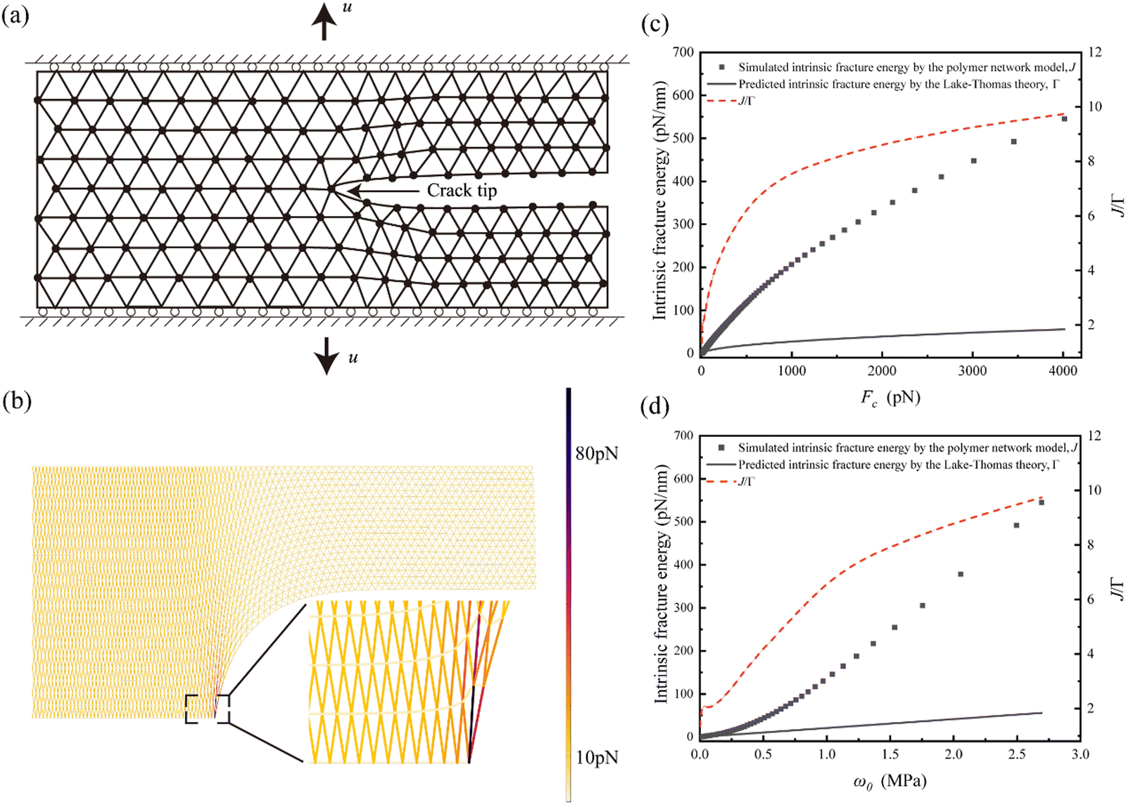 | ||
| Fig. 2 Comparison between simulated intrinsic fracture energy and predictions from the Lake–Thomas theory. (a) Simulation of a crack propagating in a strip of a triangular polymer chain network. (b) Simulated chain force contours and deformed configuration. (c) Comparison between the simulated intrinsic fracture energy and predictions from the Lake–Thomas theory as a function of critical chain force. (d) Comparison between the simulated intrinsic fracture energy and predictions from the Lake–Thomas theory as a function of critical strain energy density. | ||
Typical force contours and deformation pattern from the simulation are displayed in Fig. 2b. The simulation terminates when the force of any individual chain reaches a predefined critical value Fc, referred to as the chain breaking force. The intrinsic fracture energy of the network is then evaluated through the J-integral,37
| J = ε0h | (1) |
According to the Lake–Thomas theory,18 the intrinsic fracture energy Γ0 could be expressed as Γ0 ≃ w0![[L with combining macron]](https://www.rsc.org/images/entities/i_char_004c_0304.gif) , where is the initial chain length typically ∼10 nm, and w0 the critical strain energy density for chain rupture at the crack tip. Following the force–stretch curve of a worm-like chain, w0 can be calculated for given Fc, and the prediction according to the Lake–Thomas theory is plotted in Fig. 2c and d.
, where is the initial chain length typically ∼10 nm, and w0 the critical strain energy density for chain rupture at the crack tip. Following the force–stretch curve of a worm-like chain, w0 can be calculated for given Fc, and the prediction according to the Lake–Thomas theory is plotted in Fig. 2c and d.
As shown in Fig. 2c and d, our results agree well with the prediction by the Lake–Thomas theory at relatively low Fc or w0, where the corresponding bond breaking force falls below ∼100 pN. At relatively high Fc or w0, e.g., as the bond breaking force reaches ∼1 nN, our simulated intrinsic fracture energy is significantly larger than the prediction of the Lake–Thomas theory, with up to ∼500% discrepancy. It should be noted that we have adopted a modern description of the Lake–Thomas theory18 in the current work, where the energy for the rupture of a single polymer chain is calculated as the integral of the force–stretch curve of the worm-like chain.36 In our view, this approach is more reasonable than the original treatment proposed in the Lake–Thomas theory,18 which assumes that the energy required to rupture a single polymer chain is the product of the number of chemical bonds in the main chain and the rupture energy of a single chemical bond. However, we acknowledge that the discrepancy between the theory and simulation, as shown in Fig. 2, could be smaller if the original treatment from the Lake–Thomas theory18 were adopted.
To understand the origin of such discrepancy, we plot the force contour of individual chains in the vicinity of the crack tip. As shown in Fig. 3a–c, the chain forces are highly concentrated at the crack tip and decay rapidly over a few neighboring chains. The decay distance along the vertical direction increases with Fc. We let the crack tip advance by breaking a single polymer chain at the crack tip and calculate the associated changes in chain force within the network. The results in Fig. 3d–f reveal that the dissipation zone associated with crack propagation can involve a few layers in the vertical direction, and the larger the Fc, the more layers are involved.
 | ||
| Fig. 3 Simulated crack tip force and deformation fields. (a)–(c) Chain force contours in the vicinity of the crack tip under different Fc. (d)–(f) Change in chain forces upon crack propagation by breaking a single polymer chain at the crack tip under different Fc. Only changes in chain force above a small threshold value, ΔF, are plotted, where, ΔF = 12 pN in (d), 45 pN in (e), and 134 pN in (f), respectively. | ||
The above results indicate that multiple layers of chains are involved in crack advance at the fatigue threshold, thereby challenging the assumption in the Lake–Thomas theory that only a single layer of polymer chains contributes to the intrinsic fracture energy of a polymeric material, especially when the chain-breaking force can reach that of a covalent bond on the order of approximately 1 nN.38 Nevertheless, our simulation results are in agreement with the commonly held view in the literature7 that the intrinsic fracture energy of a polymer network—following the worm-like chain theory36 for the force–stretch behavior of individual chains and assuming a chain-breaking force below approximately 1 nN—generally scales with, and is therefore limited by, the initial length of individual chains, i.e.
| J0 ∼ w0 | (2) |
Result
To explore the possibility of overcoming the size limitation imposed by the initial chain length in eqn (2), we next investigate the intrinsic fracture energy of a polymer network with periodically distributed pores, where the polymer matrix forms a network-like structure at a much larger scale than a single polymer chain. Similar to experiments,39 the pure-shear model of a plane-stress cracked strip is employed to determine the intrinsic fracture energy (Fig. 4a). In this model, pores with radius a are square-shaped with rounded corners and are uniformly distributed in two patterns: stacked and staggered, as illustrated in Fig. 4b and c. The walls between neighboring pores have a consistent thickness t. Since a soft or debonded inclusion tends to attract cracks,40 we focus on the scenario where the crack tip is situated within a pore. | ||
| Fig. 4 Simulation model of a porous polymer network. (a) A mode I crack propagating in a hydrogel strip with pores. (b) Stacked pores. (c) Staggered pores. | ||
Using a two-scale approach, we integrate the polymer network model with the traditional FEM to simulate a strip containing a high density of pores. First, we simulate the stretching of the porous structures at the macroscopic scale using FEM to obtain the global displacement field. Then, we focus on a region near the crack tip and build the corresponding polymer network model containing a few pores at the microscopic scale, as shown in Fig. 5e, h and Fig. S1, S2 (ESI†). Following some of the examples provided in COMSOL, the displacements along the interacting boundaries of the polymer network model with the macroscopic porous structure are directly obtained from the FEM simulation and fixed during the micro-scale polymer network simulation. This approach can be justified by recognizing that FEM analysis is expected to hold in regions relatively far from the crack tip, where stress variations are gradual, while the polymer network model offers refined analysis near the crack tip, where stress changes more rapidly. This step-by-step simulation process concludes when the maximum force within the chains in the polymer network model near the crack tip reaches the critical force value. At this point, the corresponding intrinsic fracture energy is calculated using the J-integral.37 A flowchart of the simulation scheme described above is provided in Fig. S3 (ESI†).
 | ||
| Fig. 5 Simulation results. (a) Simulated J/w0 is nearly proportional to the pore size under fixed wall thickness, and the nondimensional value J/w0a ∼ 2.5 for all cases; (b) under fixed pore size, J/w0 varies little with the wall thickness and J/w0a ∼ 2.5 for all cases; (c) J/w0a increases with Fc; typical simulated force contours within the walls at the crack tip in the stacked model (d) and (e) and in the staggered model (g) and (h); typical simulated strain energy density contours in the stacked model (f) and staggered model (i). Note that the strain energy density distribution is almost uniform at the crack tip. | ||
This two-scale methodology begins with an initial simulation using the FEM in COMSOL. Taking advantage of symmetry, only half of the strip is modeled. The strip length is chosen to be sufficiently large, and the horizontal displacement is constrained at the far right side of the strip to enhance convergence. For simplicity and without loss of generality, in the FEM, we employ the incompressible Arruda–Boyce model,41 which incorporates two material parameters: the locking stretch λm of polymer chains, and the shear modulus μ.
At the lower scale, we focus on a localized region near the crack tip, where the displacements calculated from the FEM are imposed as boundary conditions to model the forces and stretches within the polymer chain network. For the truss elements, we employ the polynomial series of the Langevin chain model42–44 to describe the force–stretch behavior of individual chains,  . In addition, solid elements are adopted to model a nearly incompressible neo-Hookean hyperelastic materials with a large bulk modulus of κ and a small shear modulus of G. The hydrostatic stress in the solid elements is enforced as
  , where F3 is the Langevin chain force with extension λ3ld, λ3 being the out-of-plane stretch. Note that, in the employed Arruda–Boyce model,41μ is obtained by fitting the stress–stretch curves under uniaxial tension and
  λs denoting the free-swelling stretch.
The two-scale simulation continues until the maximum chain force in the vicinity of the crack tip reaches the critical threshold value, Fc. At this point, we evaluate the average strain energy w1 far ahead of the crack tip and determine the intrinsic fracture energy J as the product of w1 and the strip height37 under two sets of parameters: the first set varies the pore size while keeping the wall thickness fixed, and the second set changes the wall thickness while maintaining a constant pore size. The computed J/w0 are displayed in Fig. 5. The simulation results shown in Fig. 5 indicate that J/w0 can significantly exceed for both pore patterns. The simulated J increases almost linearly with pore size under fixed wall thickness (Fig. 5a). Conversely, enlarging the wall thickness under fixed constant pore size only affects J/ω0 slightly (Fig. 5b). The effect of the chain breaking force, Fc, is displayed in Fig. 5c, where J/(w0a) increases with Fc.
To make sense of the simulation results, we examine the deformation and force distribution in the crack tip region. As shown in Fig. 5d–i for both stacked and staggered pore patterns, the walls directly at the crack tip are largely under uniaxial loading with a nearly uniform strain energy density distribution. This is mainly attributed to the pore–pore interaction. Without this interaction, chain forces within the walls near the crack tip would be highly concentrated, as predicted by classical fracture mechanics theories.45 As shown in Fig. S4 (ESI†), the chain forces within the wall closest to the crack tip become more evenly distributed as the pore size increases.
To understand why the intrinsic fracture energy scales with pore size, we note that the walls between pores near the crack tip can be regarded as a type of supercohesive bonds, where the stored elastic energy is released upon crack propagation (Fig. 6). For an interface with a periodic cohesive energy distribution, it has been shown that the apparent fracture energy falls between the peak and average values of the cohesive energy, depending on the relationship between the size of the cohesive zone and the periodicity of the energy distribution, lc, and the period of the cohesive energy distribution, lp.46 For lc ≪ lp, the apparent fracture energy of the interface is the peak value of the cohesive energy. Conversely, when lp ≪ lc, the apparent fracture energy of the interface becomes equal to the average value of the cohesive energy.
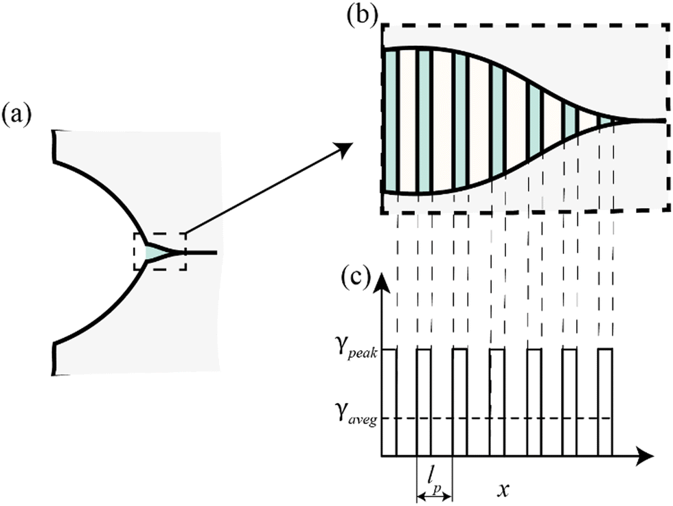 | ||
| Fig. 6 Cohesive model of crack propagation in porous hydrogel networks. (a) Schematic of a cohesive crack model incorporating periodic supercohesive bonds. (b) Representation of the walls between pores in a porous hydrogel network as periodic supercohesive bonds. (c) Modeling of periodic cohesive bonds as a periodic distribution of cohesive energy. | ||
In the case of a highly porous hydrogel network displayed in Fig. 4, the average cohesive energy is
 | (3) |
 | (4) |
As shown in Fig. 5a and b, the simulated intrinsic fracture energy is roughly
| J1 ∼ 2.5w0a, | (5) |
Discussion and conclusion
A chain network model has been developed to investigate the intrinsic fracture energy of hydrogels and to compare it with the Lake–Thomas theory, which relates intrinsic fracture energy to the breaking of a single layer of polymer chains along the crack plane. By employing force–stretch curves of individual chains based on the worm-like chain theory36 and accounting for the impressibility of the network, our findings generally support a broad interpretation of the Lake–Thomas theory, demonstrating that the intrinsic fracture energy scales with the initial length of the constituent polymer chains and involves a chain-breaking force that is not excessively high. Our analysis reveals that chain scission is typically not confined to a single layer of chains but can involve multiple layers, as recently speculated in the literature.19It should be noted that in deriving the classical Lake–Thomas theory,18 it was assumed that nearly all monomer units within a single polymer chain would rupture simultaneously during chain dissociation. However, this assumption does not necessarily hold true in reality. The more modern Lake–Thomas theory addresses this limitation by employing the critical strain energy density, calculated based on the integration of the force–extension curve of a single polymer chain upon dissociation. This modern formulation, as represented by eqn (2) in our work, is now widely used in predicting the fatigue threshold of soft materials.7,12,47 Interestingly, a similar form of eqn (2) was also introduced in the original work by Lake and Thomas,18 under the section titled Alternative Approach.
Our analysis is consistent with a recent study,48 where energy dissipation from chains far from the crack tip was found to contribute to the intrinsic fracture energy of polymer networks. In that work,48 the intrinsic fracture energy of polymer networks was also found to be several times the Lake–Thomas prediction when the ratio of the stiff energetic modulus to the soft entropic modulus of individual chains in their polymer network model was approximately 1000.48 However, when this ratio increased to a very high value, for example, 2 × 10⁴, along with the selection of a very high chain-breaking force of 5 nN, the intrinsic fracture energy was found to be almost two orders of magnitude higher than the Lake–Thomas prediction.48 It is important to note that incompressibility was not enforced in their polymer network model,48 despite it being a general requirement for soft polymeric materials. In contrast, incompressibility has been properly incorporated in our polymer network model.
Recently, through a combination of simulations and experiments, a new scaling law for the intrinsic fracture energy of polymer networks composed of stretchable strands was revealed.49 This scaling law demonstrated its applicability across multiple length scales and indicated that the Lake–Thomas theory is not applicable, particularly when the force–stretch curve of a single strand in the network is highly nonlinear. In such cases, energy dissipation during crack propagation involves multiple layers of chains. Additionally, the scaling law suggested that the intrinsic fracture energy of a polymer network can be significantly enhanced by increasing the length of individual strands. These findings are consistent with our own results considering rather uniform stress distribution with individual strands.
In calculating the intrinsic fracture energy of a polymer network with periodically distributed pores using the integration of FEM and the chain network model, our analysis further indicates that the intrinsic fracture energy of a highly porous network can scale with the pore size rather than the chain length. Considering that chain lengths are typically on the order of approximately 10 nm and pore sizes on the order of approximately 1 μm, this implies that the intrinsic fracture energy of a highly porous network could reach orders of magnitude higher than that of a homogeneous network. In other words, our analysis suggests that micropores in soft materials could significantly magnify the intrinsic fracture energy under certain conditions.
The intrinsic fracture energy of polymer networks, as measured in experiments,14,17,50 was found to be nearly two orders of magnitude greater than the Lake–Thomas prediction.48 This substantial discrepancy was previously attributed to a nonlocal energy dissipation mechanism involving the relaxation of chains far from the crack tip, which is closely tied to the high ratio of the stiff energetic modulus to the soft entropic modulus of individual chains within the polymers.48 However, based on eqn (2)–(4), our studies suggest an alternative explanation: the presence of micropores within polymers may contribute to this significant difference in intrinsic fracture energy.
In our simulations, the distribution of strain energy density across the wall thickness between neighboring pores is nearly uniform. However, this uniformity does not hold as the wall thickness becomes sufficiently large, which could reduce the amount of strain energy stored prior to reaching the fatigue threshold. Consequently, this leads to an intrinsic fracture energy that is lower than previously predicted. In this context, it is important to note that there exists a critical wall thickness for flaw tolerance, below which the strain energy density distribution remains uniform.51 Therefore, introducing sufficiently small, densely packed, and hierarchically structured pores with appropriately thin walls could be an effective strategy to achieve a more uniform distribution of strain energy density and significantly enhance the intrinsic fracture energy.
Indeed, the fabrication of hydrogels with hierarchical pores is a promising area of research. For instance, the integration of directional freeze-casting and subsequent salting-out treatments has recently enabled the fabrication of hydrogels with multi-length-scale hierarchical structures.52 These hydrogels feature micrometer-scale honeycomb-like pore walls composed of interconnected nanofibril meshes. Despite having a water content of up to 95 percent, these hydrogels exhibit high strength, toughness, and fatigue threshold, making them comparable to other robust hydrogels and even natural tendons.
Our analysis also suggests that the ubiquitous pores present in native tissues may play a role in contributing to their intrinsic fracture energy, potentially enhancing their resistance to cyclic loading. For instance, both experimental and simulation data have shown that the presence of pores in echinoderm stereom can reduce stress concentrations within the stereom, enabling high relative strength and significant energy absorption capabilities.53 Similarly, diffused damage in bone, often caused by daily activities, typically spans approximately 1 μm in length and has been shown to be highly effective in energy absorption.54 Interestingly, our analysis suggests that age-related reductions in the formation of such diffused damage may partly account for the decline in fracture properties observed in aging bones.
Data availability
The data that support the findings of this study are available from the corresponding author upon reasonable request.Conflicts of interest
There are no conflicts of interest to declare.Acknowledgements
This work was supported by Zhejiang Provincial Natural Science Foundation of China (Grant No.: LZ23A020004) and the National Natural Science Foundation of China (Grant No.: 12372318).References
- M. Farokhi, F. Jonidi Shariatzadeh, A. Solouk and H. Mirzadeh, Int. J. Polym. Mater., 2020, 69, 230–247 CrossRef.
- K. Y. Lee and D. J. Mooney, Chem. Rev., 2001, 101, 1869–1880 CrossRef PubMed.
- Y. Lee, W. J. Song and J. Y. Sun, Mater. Today Phys., 2020, 15, 100258 CrossRef.
- S. Lin, H. Yuk, T. Zhang, G. A. Parada, H. Koo, C. Yu and X. Zhao, Adv. Mater., 2016, 28, 4497–4505 CrossRef PubMed.
- G. Su, J. Cao, X. Zhang, Y. Zhang, S. Yin, L. Jia, Q. Guo, X. Zhang, J. Zhang and T. Zhou, J. Mater. Chem. A, 2020, 8, 2074–2082 RSC.
- J. Liu, S. Lin, X. Liu, Z. Qin, Y. Yang, J. Zang and X. Zhao, Nat. Commun., 2020, 11, 1071 CrossRef PubMed.
- J. Tang, J. Li, J. J. Vlassak and Z. Suo, Extreme Mech. Lett., 2017, 10, 24–31 CrossRef.
- H. Lei, L. Dong, Y. Li, J. Zhang, H. Chen, J. Wu, Y. Zhang, Q. Fan, B. Xue, M. Qin, B. Chen, Y. Cao and W. Wang, Nat. Commun., 2020, 11, 4032 CrossRef PubMed.
- S. Lin, X. Liu, J. Liu, H. Yuk, H. C. Loh, G. A. Parada, C. Settens, J. Song, A. Masic, G. H. McKinley and X. Zhao, Sci. Adv., 2019, 5, eaau8528 CrossRef PubMed.
- C. Xiang, Z. Wang, C. Yang, X. Yao, Y. Wang and Z. Suo, Mater. Today, 2020, 34, 7–16 CrossRef.
- R. Bai, J. Yang, X. P. Morelle, C. Yang and Z. Suo, ACS Macro Lett., 2018, 7, 312–317 CrossRef PubMed.
- X. Li and J. P. Gong, Nat. Rev. Mater., 2024, 9, 380–398 CrossRef.
- W. Zhang, X. Liu, J. Wang, J. Tang, J. Hu, T. Lu and Z. Suo, Eng. Fract. Mech., 2018, 187, 74–93 CrossRef.
- Y. Akagi, H. Sakurai, J. P. Gong, U. Chung and T. Sakai, J. Chem. Phys., 2013, 139, 144905 CrossRef.
- C. Yang and Z. Suo, Nat. Rev. Mater., 2018, 3, 125–142 CrossRef.
- K. Mayumi, C. Liu, Y. Yasuda and K. Ito, Gels, 2021, 7, 91 CrossRef PubMed.
- C. W. Barney, Z. Ye, I. Sacligil, K. R. McLeod, H. Zhang, G. N. Tew, R. A. Riggleman and A. J. Crosby, Proc. Natl. Acad. Sci. U. S. A., 2022, 119, e2112389119 CrossRef CAS PubMed.
- G. J. Lake and A. G. Thomas, Proc. R. Soc. London, Ser. A, 1967, 300, 108–119 Search PubMed.
- R. Bai, J. Yang and Z. Suo, Eur. J. Mech. – ASolids, 2019, 74, 337–370 CrossRef.
- W. Zhang, J. Hu, J. Tang, Z. Wang, J. Wang, T. Lu and Z. Suo, ACS Macro Lett., 2019, 8, 17–23 CrossRef CAS PubMed.
- S. Wang, L. Li, D. Su, K. Robin and K. A. Brown, ACS Appl. Mater. Interfaces, 2018, 10, 34604–34610 Search PubMed.
- S. M. Lanasa, I. T. Hoffecker and S. J. Bryant, J. Biomed. Mater. Res., Part B, 2011, 96, 294–302 Search PubMed.
- M. Li, Z. Wu, C. Zhang, S. Lu, H. Yan, D. Huang and H. Ye, J. Appl. Polym. Sci., 2001, 79, 2192–2199 Search PubMed.
- U.-J. Kim, J. Park, C. Li, H.-J. Jin, R. Valluzzi and D. L. Kaplan, Biomacromolecules, 2004, 5, 786–792 CrossRef CAS PubMed.
- R. V. Badhe, D. Bijukumar, D. R. Chejara, M. Mabrouk, Y. E. Choonara, P. Kumar, L. C. du Toit, P. P. D. Kondiah and V. Pillay, Carbohydr. Polym., 2017, 157, 1215–1225 CrossRef CAS PubMed.
- J. Grenier, H. Duval, F. Barou, P. Lv, B. David and D. Letourneur, Acta Biomater., 2019, 94, 195–203 CrossRef CAS PubMed.
- F. Dehli, A. Southan, W. Drenckhan and C. Stubenrauch, J. Colloid Interface Sci., 2021, 588, 326–335 CrossRef CAS PubMed.
- B. Göttel, J. M. de Souza, E. Silva, C. Santos De Oliveira, F. Syrowatka, M. Fiorentzis, A. Viestenz, A. Viestenz and K. Mäder, Eur. J. Pharm. Biopharm., 2020, 146, 125–132 Search PubMed.
- K. Ziv, H. Nuhn, Y. Ben-Haim, L. S. Sasportas, P. J. Kempen, T. P. Niedringhaus, M. Hrynyk, R. Sinclair, A. E. Barron and S. S. Gambhir, Biomaterials, 2014, 35, 3736–3743 CrossRef CAS PubMed.
- C. Ji, A. Khademhosseini and F. Dehghani, Biomaterials, 2011, 32, 9719–9729 Search PubMed.
- T. Asoh, M. Matsusaki, T. Kaneko and M. Akashi, Adv. Mater., 2008, 20, 2080–2083 CrossRef CAS.
- G. Alamé and L. Brassart, Soft Matter, 2019, 15, 5703–5713 Search PubMed.
- K. Kothari, Y. Hu, S. Gupta and A. Elbanna, J. Appl. Mech., 2018, 85, 031008 Search PubMed.
- J. Lei, Z. Li, S. Xu and Z. Liu, J. Mech. Phys. Solids, 2021, 156, 104599 Search PubMed.
- J. Lei and Z. Liu, J. Appl. Phys., 2022, 132, 135101 Search PubMed.
- J. F. Marko and E. D. Siggia, Macromolecules, 1995, 28, 8759–8770 Search PubMed.
- J. R. Rice, J. Appl. Mech., 1968, 35, 379–386 Search PubMed.
- M. I. Giannotti and G. J. Vancso, ChemPhysChem, 2007, 8, 2290–2307 CrossRef CAS PubMed.
- R. S. Rivlin and A. G. Thomas, J. Polym. Sci., 1953, 10, 291–318 Search PubMed.
- K. Guo, B. Ni and H. Gao, Int. J. Fract., 2020, 222, 13–23 Search PubMed.
- E. M. Arruda and M. C. Boyce, J. Mech. Phys. Solids, 1993, 41, 389–412 Search PubMed.
- W. Kuhn and F. Grün, Kolloid-Z., 1942, 101, 248–271 Search PubMed.
- L. R. G. Treloar, Trans. Faraday Soc., 1954, 50, 881 Search PubMed.
- J. S. Palmer and M. C. Boyce, Acta Biomater., 2008, 4, 597–612 Search PubMed.
- E. E. Gdoutos, Fracture mechanics: An introduction, Springer International Publishing, Cham, 2020, vol. 263 Search PubMed.
- B. Chen, X. Shi and H. Gao, Proc. R. Soc. London, Ser. A, 2008, 464, 657–671 CAS.
- C. Li, H. Yang, Z. Suo and J. Tang, J. Mech. Phys. Solids, 2020, 134, 103751 CrossRef.
- B. Deng, S. Wang, C. Hartquist and X. Zhao, Phys. Rev. Lett., 2023, 131, 228102 CrossRef CAS PubMed.
- C. Hartquist, S. Wang, Q. Cui, W. Matusik, B. Deng and X. Zhao, arXiv, 2024, preprint, arXiv:arXiv:2401.05564, https://arxiv.org/abs/2401.05564.
- S. Wang, H. K. Beech, B. H. Bowser, T. B. Kouznetsova, B. D. Olsen, M. Rubinstein and S. L. Craig, J. Am. Chem. Soc., 2021, 143, 3714–3718 CrossRef CAS PubMed.
- H. J. Gao and S. H. Chen, J. Appl. Mech., 2005, 72, 732–737 Search PubMed.
- M. Hua, S. Wu, Y. Ma, Y. Zhao, Z. Chen, I. Frenkel, J. Strzalka, H. Zhou, X. Zhu and X. He, Nature, 2021, 590, 594–599 Search PubMed.
- T. Yang, Z. Jia, Z. Wu, H. Chen, Z. Deng, L. Chen, Y. Zhu and L. Li, Nat. Commun., 2022, 13, 1–12 Search PubMed.
- A. Ural and D. Vashishth, Int. Mater. Rev., 2014, 59, 245–263 Search PubMed.
Footnote |
| † Electronic supplementary information (ESI) available. See DOI: https://doi.org/10.1039/d4sm00973h |
| This journal is © The Royal Society of Chemistry 2025 |