
 Open Access Article
 This Open Access Article is licensed under a Creative Commons Attribution-Non Commercial 3.0 Unported Licence
Bimetallic effects in carbon dioxide electroreduction
Anaer
Husile
,
Zhenlu
Wang
 * and
Jingqi
Guan
*
* and
Jingqi
Guan
*
State Key Laboratory of Inorganic Synthesis and Preparative Chemistry, Institute of Physical Chemistry, College of Chemistry, Jilin University, 2519 Jiefang Road, Changchun 130021, P. R. China. E-mail: wzl@jlu.edu.cn; guanjq@jlu.edu.cn
First published on 5th March 2025
Abstract
As a clean and sustainable technology, electrocatalytic carbon dioxide reduction reaction (ECO2RR) occupies a central position in the global energy transformation and climate change strategy. Compared with single metallic catalysts, bimetallic catalysts have many advantages, such as the synergistic effect between bimetals, enhanced CO2 adsorption capacity, and lower reaction energy barriers, which make them widely used in the CO2RR for the generation of multi-carbon products. This review systematically summarizes the latest advances in bimetallic effects for the CO2RR. In this paper, we start with a classified introduction on the CO2RR mechanisms, followed by a comprehensive discussion of the structure–activity relationships of various bimetallic catalysts, including regulation of metal centers, regulation of the distance between metal sites, regulation of the coordination environment, interface engineering, and strain engineering. Next, we showcase the advantages of bimetallic catalysts in the CO2RR. Then, the research progress of typical bimetallic catalysts for the ECO2RR is discussed, including diatomic catalysts, bimetallic alloys, bimetallic MOFs and bimetallic COFs. Finally, we summarize the challenges faced today from the five aspects of product selectivity, catalyst stability, product purification, theoretical simulations and in situ characterization techniques and put forward the research direction to promote the industrialization process of CO2RR.
 Anaer Husile | Anaer Husile received her BS degree from Inner Mongolia Normal University in 2023. Currently, she is a Master's candidate at Jilin University under the supervision of Prof. Jingqi Guan and Prof. Zhenlu Wang. Her research focuses on the synthesis of single-/multi-atom catalysts for energy conversion and storage. |
 Jingqi Guan | Jingqi Guan is currently a Professor of Chemistry at Jilin University. He received his BS and PhD degrees in chemistry from Jilin University. He worked as a postdoctoral research fellow at the University of California at Berkeley from 2012 to 2013 and at the Dalian Institute of Chemical Physics from 2014 to 2018. His research interests are in engineering single-/multi-atom catalysts and 2D materials for electrocatalysis, energy, and the environment. He is on the Editorial Boards of Chin. J. Catal., Acta Phys.-Chim. Sin., and EcoEnergy. He has published more than 240 peer-reviewed papers. |
1. Introduction
Climate problems such as the greenhouse effect caused by excessive exploitation and utilization of fossil fuels have seriously affected human life.1–6 Therefore, fundamentally solving the excessive emission of carbon dioxide has become a difficult problem.7–9 Since the ‘double carbon’ target was proposed in 2020, researchers have been committed to developing green, environmentally friendly and efficient CO2 conversion technologies. Nowadays, the electrochemical CO2 reduction method is a green method for sustainable development.10 Through electrochemical processes, CO2 can be reduced to high value-added products for industrial production, which can effectively alleviate the climate crisis while realizing resource utilization.11 The main problems hindering the development of electrocatalytic reduction of CO2 are the high potential required for the reaction and low product selectivity,12,13 which are due to high thermodynamic stability of CO2 and complex proton electron transfer pathways in the conversion process. Among a variety of CO2 reduction products, CO generation has low overpotential and high Faraday efficiency and has great development potential in the future.14,15 In addition, CO can be further converted into high-value industrial raw materials such as methane, methanol, and ethanol, thereby achieving a high carbon cycle. However, these processes still need to be achieved with the assistance of catalysts. The competition of the hydrogen evolution side reaction caused by the reactivity and structural diversity of catalytic materials will further affect the product selectivity of the main reaction of CO2 reduction. Therefore, the development of efficient electrocatalysts to promote the CO2 reduction process is a key issue that needs to be solved.Nowadays, no matter what type of metal catalyst, the reduction process is basically carried out through the steps of CO2 adsorption on the catalyst surface, electron transfer and final product desorption.16,17 Due to the difference in the adsorption capacity of different atoms, different reaction products (C1, C2, and C3) are generated. The adsorption behaviour of metal elements on different intermediates determines the type of final product. Metal elements such as Au, Ag and Zn tend to generate CO.18,19 Metal element-based catalysts such as Hg, In and Sn mainly generate HCOO−/HCOOH, while Cu is the most efficient C2+ product catalyst reported so far.20–24 Metals such as Ni, Fe and Pt show low catalytic activity for CO2 reduction, mainly generating H2. In addition, the binding strength between *CO and metal-based catalysts also affects the product selectivity.25,26 Weak adsorption tends to produce low electron transfer products, while strong adsorption will produce hydrocarbon products. Through continuous exploration, great achievements have been made in electrochemical CO2 reduction in recent years. Among them, bimetallic-based catalysts show higher catalytic performance for CO2RR than single-metal catalysts.27–29 The synergistic effect between two metals can effectively regulate the selectivity of the reaction and reduce the occurrence of the HER, thereby obtaining higher selectivity of the target product.30,31 In addition, bimetallic systems are more stable than single metal catalysts, which effectively alleviates the deactivation or degradation of the catalysts during the reaction. At present, the types of bimetallic catalysts mainly include diatomic catalysts, bimetallic alloys, bimetallic MOFs and bimetallic COFs. The synergistic effect of bimetallic sites can effectively promote the rapid movement of CO2 molecules and accelerate the formation of key intermediates, thereby accelerating the CO2RR process.32,33 The adjustability of the electronic structure of two adjacent metal active centers helps enhance the CO2RR kinetics and has an important influence on the product selectivity. Compared with single metal catalysts, bimetallic catalysts can adjust the d-band center through the interaction of electronic orbitals, thereby adjusting the binding energy of reaction intermediates and accelerating the reaction rate.34,35 Therefore, bimetallic catalysts have received a lot of attention in the electrochemical CO2RR recently as shown in Fig. 1.
 | ||
| Fig. 1 Research progress of electrochemical CO2RR on bimetallic catalysts. Reproduced with permission.36 Copyright 2014, Springer Nature. Reproduced with permission.37 Copyright 2015, Wiley-VCH. Reproduced with permission.38 Copyright 2019, American Chemical Society. Reproduced with permission.39 Copyright 2020, Springer Nature. Reproduced with permission.40 Copyright 2021, Elsevier Ltd. Reproduced with permission.41 Copyright 2022, Wiley-VCH. Reproduced with permission.42 Copyright 2023, Springer Nature. Reproduced with permission.43 Copyright 2024, Springer Nature. | ||
In this review, we introduced the reaction mechanism of CO2RR in detail and focused on the structure–activity relationship of bimetallic catalysts. Subsequently, we summarized four frontier catalysts, including diatomic catalysts, bimetallic alloy catalysts, bimetallic MOFs and bimetallic COFs, and discussed the catalytic activity and CO2RR mechanism in detail. Finally, we summarized the challenges faced by bimetallic catalysts in the CO2RR process and put forward substantive suggestions, pointing out the direction for future research.
2. Carbon dioxide reduction mechanism
Due to large ionization energy and small electron affinity of CO2 molecules, it is possible to reduce CO2 to high value-added products. Among them, the electrochemical reduction method can be used to obtain different reaction products by changing the condition parameters (such as voltage, current, electrolyte, etc.) and become the main technical means for the controllable reduction of carbon dioxide.44 Previous studies have shown that CO2 can be reduced to C1 products such as CO, formic acid, methanol and methane and C2 products such as ethylene, CH3CH2OH and CH3CHO.45–47 However, due to the complexity of the electrochemical reduction process and the difference in the standard redox potential of different electron transfer pathways (Table 1), ECO2RR technology still faces many challenges, for example, slow reaction kinetics, complex reaction pathways and mechanisms, and low catalytic activity. The fundamental solution to the above problems is to infer the key intermediates and the optimal reaction path, so as to improve the catalytic materials. This section introduces the mechanism of CO2RR in detail.| Acidic medium | Basic medium | ||
|---|---|---|---|
| Equation | E (V) | Equation | E (V) |
| 2H+ + 2e− → H2 | 0.000 | 2H2O + 2e− → H2 + 2OH− | −0.828 |
| CO2 + 2H+ + 2e− → CO + H2O | −0.104 | CO2 + H2O + 2e− → CO + 2OH− | −0.932 |
| CO2 + 2H+ + 2e− → HCOOH | −0.171 | CO2 + H2O + 2e− → HCOO− + OH− | −0.639 |
| CO2 + 4H+ + 4e− → HCHO + H2O | −0.142 | CO2 + 3H2O + 4e− → HCHO + 4OH− | −0.970 |
| CO2 + 6H+ + 6e− → CH3OH + H2O | 0.016 | CO2 + 5H2O + 6e− → CH3OH + 6OH− | −0.812 |
| CO2 + 8H+ + 8e− → CH4 + 2H2O | 0.169 | CO2 + 6H2O + 8e− → CH4 + 8OH− | −0.659 |
| 2CO2 + 10H+ + 10e− → CH3CHO + 3H2O | 0.053 | 2CO2 + 7H2O + 10e− → C2H4O + 10OH− | −0.775 |
| 2CO2 + 8H+ + 8e− → CH3COOH + 2H2O | 0.098 | 2CO2 + 5H2O + 8e− → CH3COO− + 7OH− | −0.653 |
| 2CO2 + 12H+ + 12e− → CH2CH2 + 4H2O | 0.085 | 2CO2 + 8H2O + 12e− → CH2CH2 + 12OH− | −0.743 |
| 2CO2 + 12H+ + 12e− → C2H5OH + 3H2O | 0.084 | 2CO2 + 9H2O + 12e− → C2H5OH + 12OH− | −0.744 |
| 2CO2 + 2H+ + 2e− → H2C2O4 | −0.595 | 2CO2 + 2e− → C2O42− | −0.595 |
| 2CO2 + 6H+ + 6e− → CHOCHO + 2H2O | −0.141 | 2CO2 + 4H2O + 6e− → CHOCHO + 6OH− | −0.969 |
| 2CO2 + 8H+ + 8e− → CH2OHCHO + 2H2O | −0.057 | 2CO2 + 6H2O + 8e− → CH2OHCHO + 8OH− | −0.885 |
| 3CO2 + 18H+ + 18e− → C3H7OH + 5H2O | 0.095 | 2CO2 + 13H2O + 18e− → C3H7OH + 18OH− | −0.733 |
2.1. Formation mechanism of HCOO−/HCOOH and CO
The reduction of CO2 to HCOO−/HCOOH and CO is carried out through a 2-electron transfer pathway, and the steps are relatively simple. When CO2 is saturated in the electrolyte solution, it will be adsorbed on the catalyst surface and excited into *CO2− radicals. *CO2− radicals are combined with protons and electrons to form different final products. From the previous research results, the formation path of HCOO−/HCOOH is mainly divided into the following five types: CO2 can be directly connected to metal hydrogen bonds, or can be combined with H+ in the solution to form a *COOH intermediate connected to a single oxygen or double oxygen, and then further protonated to form HCOOH. Another way is that the C atom in CO2 is connected to the catalyst to form related intermediates, thereby generating HCOO−.48 In addition, CO2 can also combine with the hydroxyl groups in the electrolyte to form HCOO− by protonation.49 The formation path of CO is relatively uniform, that is, CO2 is carried through proton coupling and electron transfer paths. In this process, the *COOH intermediate is generated, and *COOH is further dehydrated and protonated, which promotes the CO2 absorbed on the catalyst surface to dissociate and generate CO (Fig. 2).50 | ||
| Fig. 2 Mechanism diagram of HCOO−/HCOOH and CO formation. | ||
2.2. Formation mechanism of methane, methanol and formaldehyde
CH4, CH3OH and HCHO are usually evolved from *CO intermediates. *CHO and *CH2O are formed by electron transfer and hydrogenation of *CO, and then HCHO is formed. The *CH2O is further hydrogenated to form the *CH3O intermediate. The *CH3O can be reduced to CH3OH, or the C–O bond may be broken to reduce to CH4. In addition, the *CO intermediate can also be selectively transformed into *COH. The C–O bond of *COH is broken and dehydrated to form adsorbed carbon, which is protonated to form *CH, *CH2 and *CH3, and finally CH4 is generated (Fig. 3).51 | ||
| Fig. 3 Mechanism diagram of methane, methanol and formaldehyde formation. | ||
2.3. Formation mechanism of ethylene, acetaldehyde and ethanol
The key to the reduction of CO2 to C2 products is the coupling of C–C bonds.52,53 At present, the dimerization and carbene mechanism of the *CO intermediate is considered to be a reasonable reaction mechanism.54 The dimerization of the *CO intermediate refers to the proton–electron transfer of two *CO on the surface of a catalyst to form a *C2O2− intermediate. One C and one O atom in *C2O2− bind to two adjacent atoms on the surface of the catalyst, so that the remaining CO group is negatively charged, and CO is further protonated into *CO–COH.55 The *CO–COH intermediate can be converted to *CCO on the (100) crystal plane of Cu, and *OCH–CH2 is formed by two-step reduction to generate CH3CHO or CH2CH2.56 However, if *OCH–CH2 is further reduced to *OCH–CH3, CH3CH2OH will eventually be generated.57 If this is carried out through the carbene mechanism, the O atoms in *CO will be protonated to form *COH, which will be further reduced to *C precipitation. It is accompanied by proton electron transfer *C to *CH2. The *CH2 intermediate is prone to dimerization to form CH2CH2. However, if the coupling between *CH2 and CO occurs, *CH2![[double bond, length as m-dash]](https://www.rsc.org/images/entities/char_e001.gif) CO will be formed, which can be reduced to *CH2COH, and then CH3CH2OH will be generated, and CH3COO− may also be generated (Fig. 4).58
CO will be formed, which can be reduced to *CH2COH, and then CH3CH2OH will be generated, and CH3COO− may also be generated (Fig. 4).58
 | ||
| Fig. 4 Mechanism diagram of C2 formation. | ||
2.4. Formation mechanism of propanol
The complexity of the intermediates involved in the formation of C3 products leads to poor product selectivity and low Faraday efficiency. The C3 product mainly refers to n-propanol, and the reaction path involved is as follows: the *CO intermediate is converted to *CH2 by multi-step protonation dehydration. By coupling *CH2 with *CO, *COHCH2 is formed. *COHCH2 is then converted to *CHCH3 by protonation deoxidation. *CHCH3 and *CO are coupled again to form a *COCH2CH3 intermediate, which is protonated to form C3H7OH (Fig. 5). In summary, the CO2 electroreduction process involves a variety of intermediates. The difference between the adsorption energy of the intermediates leads to different paths. At present, the reduction of CO2 to C1 is relatively simple, and a variety of catalysts can maintain the Faraday efficiency of the product above 80%. However, the selectivity of C2 and C3 products is still low due to the involvement of a variety of complex intermediates. The main processes involved are the generation of *CO, the coupling of C–C and the hydrogenation step of the *CO intermediate.59,60 The key to improving the selectivity of C2+ products is to increase the coverage of *CO intermediates on the catalyst surface. For example, the regulation of metal centers, the regulation of metal atom spacing, the change of the coordination environment of metal atoms, and the construction of heterostructures can all enhance the adsorption capacity of the *CO intermediate on the catalyst surface, thereby effectively increasing product selectivity. In the following section, we will introduce in detail the structure–activity relationships of catalysts and the structural regulation strategies to achieve efficient catalytic conversion of CO2. | ||
| Fig. 5 Mechanism diagram of propyl alcohol formation. | ||
3. Structure–activity relationships
The key to optimizing the reactivity, product selectivity and long-term stability of electrocatalysts lies in the modification of the electronic structure of the catalyst surface. In the process of CO2RR, understanding the structure–activity relationships is crucial for the design and modification of the catalyst. Nowadays, the regulation of central atoms, the regulation of the distance between metal sites, the regulation of the coordination environment of active centers, and interface engineering have become the main regulation strategies. The in-depth exploration of the structure–activity relationships is conducive to the design and development of green and environmentally friendly catalysts, thus promoting green chemistry and sustainable development. In addition to experimental modulation methods, appropriate theoretical research strategies and computer simulation strategies can achieve high-throughput screening and optimize the reaction route, thereby accurately controlling the reaction selectivity.3.1. Regulation of metal centers
The adjustment of metal center atoms is mainly realized in heterogeneous bimetallic catalyst systems. The regulation of the metal centers will affect the electronic structure of the entire system, thereby changing the catalytic activity, stability, and product selectivity of the catalyst.61,62 The introduction of an additional metal/nonmetal into a single metal system to construct metal–metal active sites or metal–nonmetal active sites can achieve efficient CO2RR electro-transformation. Among them, the bimetallic active sites of heterogeneous DACs can balance the strong adsorption of multiple intermediates such as *COOH and *CO, which can be converted into a variety of carbon-containing products.63,64 The central atom connection in DACs can be basically summarized as bridged and non-bridged structures. The bridging structure means that two metal elements are connected by non-metallic atoms, while the two metal atoms of the non-bridging structure are directly connected. At present, metal elements with high CO2 reduction activity are mainly precious metal elements (Pt, Pd and Ir), transition metals (Cu, Fe, Ni and Co) and p-zone metal elements such as Bi and Sb.65–67 Through the precise design of the Co–Ni–N–C bimetallic-nitrogen structure, CO2 can be efficiently reduced to CO (Fig. 6a).68 The Co–Ni–N–C double active site catalyst (DASC) had excellent reduction activity for CO2RR, with a high CO Faraday efficiency of 94.1% at −0.8 V and a reaction stability for more than 40 hours (Fig. 6b and c). DFT calculations showed that CO2 is protonated to form COOH*. As shown in Fig. 6d, the Gibbs free energy of Co–Ni–N–C is 0.227 eV, while the free energy of forming H* is 1.00 eV, which is much higher than the energy barrier of COOH*. Therefore, the bimetallic sites of Co–Ni–N–C can promote the activation of CO2 and inhibit the formation of H2, which is beneficial for the formation of CO. | ||
| Fig. 6 (a) Composite graph of Co–Ni–N–C. (b) FE diagrams of different catalysts. (c) The stability diagram of Co–Ni–N–C. (d) Comparison of Gibbs free energy of different catalysts. Reproduced with permission.68 Copyright 2024, Royal Society of Chemistry. (e) In situ Raman spectra. (f) Reaction mechanism diagram. Reproduced with permission.69 Copyright 2023, Elsevier Ltd. | ||
Cu-based materials exhibit negative adsorption energy for *CO intermediates and positive adsorption energy for *H and have unique CO2RR properties.70 The introduction of a second metal atom into a Cu-based material system can adjust the electronic structure and microchemical environment of the active sites. When Bi atoms are incorporated into the Cu-based catalyst system, 85% FEHCOOH can be achieved.69 There is a CuO/CuBi2O4 interface in Cu1Bi1, which makes it easy to adsorb and activate CO2 molecules. In situ Raman spectroscopy showed that there is a Bi–O bond in Cu1Bi1 (Fig. 6e). As the applied voltage increases, the bond strength gradually decreases. At a potential of −1.18 V, Bi–O can accelerate the adsorption of CO2 and stabilize CO2−*. This intermediate is protonated to form OCHO*. Finally, under the synergistic effect of Bi–O and the interface structure, OCHO* obtains electrons and precipitates in the form of HCOOH (Fig. 6f). Wei et al. selected Ag as the second metal and introduced it into a Cu2O system. Through the interfacial catalysis of Ag–Cu2+O, efficient production of C2H4 was achieved, of which FEethylene was 66.0%.71In situ Raman spectroscopy showed that there is a high *CO coverage at the Ag–Cu2O-0.10 interface (Fig. 7a), which is conducive to C–C coupling. In addition, they also observed that the synergistic effect between Ag and Cu can induce the change of free energy to form a *COOH intermediate. With the incorporation of Ag into the Cu matrix, the electronic structure around Cu is adjusted, and the interaction between *CO–*CO and other intermediates is effectively enhanced. Specifically, at the Ag–Cu2O active interface, the C2p orbitals of the *CO–*CO intermediate are highly overlapped (Fig. 7b), which tends to generate *OCCO, further improving the C–C coupling strength and comprehensively promoting the precipitation of C2H4.
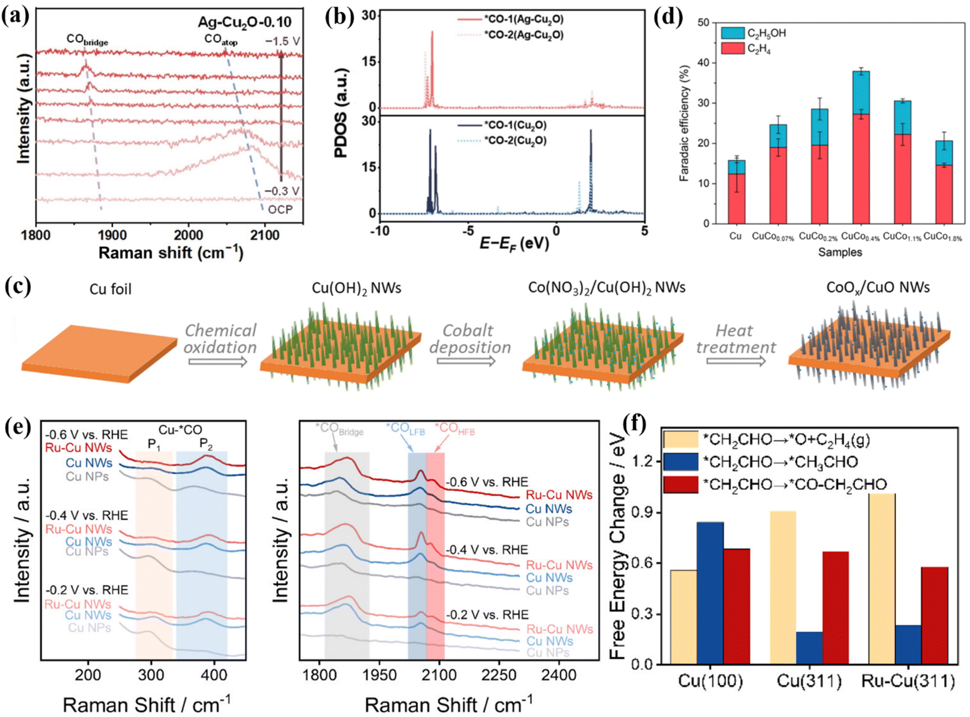 | ||
| Fig. 7 (a) In situ Raman spectra of Ag–Cu2O-0.10. (b) The PDOS comparison. Reproduced with permission.71 Copyright 2024, Wiley-VCH. (c) Composite graph of CoOx/CuO NWs. (d) FE diagrams of different catalysts. Reproduced with permission.72 Copyright 2024, OAE Publishing Inc. (e) In situ Raman spectra. (f) Free energy diagrams of different reaction pathways. Reproduced with permission.73 Copyright 2024, American Chemical Society. | ||
When Co is introduced onto the Cu surface, it shows C2H4 and CH3CH2OH selectivity.72 Co atoms are deposited on the surface of Cu NWs in an aqueous environment, and the CuCox synthesized by heat treatment has CO2RR diversity (Fig. 7c). At −1.0 V, CuCo0.4% showed 10.7% FEethanol (Fig. 7d). These Cu-based catalysts are more inclined to produce ethylene, and the production efficiency of ethanol is lower. Studies have shown that the conversion of ethylene to ethanol can be achieved by doping Ru in the Cu system to change the key intermediates of the reaction.73 A low-coordinated Cu surface (Ru–Cu NW) was constructed by doping Ru in the Cu system. By promoting CO–C2 coupling, >60% of FEC2+ alcohols and 35.9 ± 2.6% of FEn-PrOH were achieved and ultra-long stability for 100 h was achieved. In situ Raman spectroscopy showed that the doping of Ru makes the Cu surface adsorb more CO, which is beneficial to weaken the selectivity of ethylene (Fig. 7e). The large CO coverage will change its *CO binding mode, mainly in the mode of *COatop and *CObridge. Ru–Cu NWs maintain the above two adsorption modes in the system while additionally enhancing the activity of *COatop and enhancing the selectivity of C2+ alcohols. DFT studies showed that the C–O cleavage energy of the *CH2CHO intermediate plays a decisive role in the selectivity of the reaction pathway (Fig. 7f). The free energy of the EtOH/n-PrOH pathway of Ru-doped Cu is lower than that of the ethylene pathway, which is beneficial for the production of EtOH/n-PrOH (Fig. 8a).
 | ||
| Fig. 8 (a) Free energy diagram. Reproduced with permission.73 Copyright 2024, American Chemical Society. (b) The spacing of Ni–Zn. (c) ELF maps. (d) DOS diagram of Zn/Ni 3d. (e) 3D VCDD adsorption of the *COOH intermediate. (f) Free energy of different catalysts. Reproduced with permission.74 Copyright 2021, Wiley-VCH. | ||
3.2. Regulation of the distance between metal sites
In bimetallic catalyst systems, the relative position or distance between the two metal centers directly affects the adsorption mode of CO2 molecules and the stability of reaction intermediates. An appropriate space distance can optimize the adsorption mode of CO2 molecules, realize the transition from linear adsorption to bridge adsorption, and promote the activation of the CO bond. In the process of ECO2RR, the Faraday efficiency of the Ni–Zn–N6–C catalyst for CO generation can reach 99%.74 The distance between Zn and Ni atoms is 2.5 Å (Fig. 8b), and there is a bimetallic site interaction (Fig. 8c). As the distance between the Zn and Ni sites increases, the d-electron state of the metal center will change, which is conducive to the adsorption of reaction intermediates. The introduction of Zn narrows the Ni 3d orbital and Fermi level in the d-band center (Fig. 8d). Under the joint catalysis of Zn and Ni, the reaction energy barrier of the *COOH adsorption process is reduced, which promotes the desorption of CO (Fig. 7e and f).
Yao et al. studied the influence of the threshold distance of adjacent bimetallic sites on the electronic structure.75 They synthesized Ni–Cu diatomic sites on nitrogen-doped graphene with a threshold of 5.3 Å. The aberration-corrected high-angle annular dark field scanning transmission electron microscope (HAADF-STEM) results of the dNiCu-5.3 DAC showed that the Ni–Cu spacing is 0.51 nm (Fig. 9a and b). In the threshold range, the non-bonding interaction caused by Ni–Cu contact can change the electronic structure of DACs, effectively promoting the adsorption of *COOH intermediates while inhibiting the HER.
 | ||
| Fig. 9 (a and b) HAADF-STEM images. Reproduced with permission.75 Copyright 2022, Wiley-VCH. (c) Schematic diagrams of different configurations. (d) Free energy. Reproduced with permission.41 Copyright 2022, Wiley-VCH. (e) The synthesis diagram. Reproduced with permission.76 Copyright 2023, Wiley-VCH. | ||
3.3. Regulation of the coordination environment
The change in the coordination environment such as coordination space and coordination geometry has a profound influence on the catalytic activity, product selectivity and electrochemical stability of bimetallic materials, which is a key means for catalyst design and optimization.77–79 The type of ligand bound to the metal center can change the distribution of the electron cloud in the metal center, thereby changing the electron density and redox potential. In addition, the spatial arrangement and steric effect of ligands also affect the exposure of active sites.80–82 Therefore, the dynamic regulation of the coordination environment can achieve the optimal path selection and efficiency maximization of the CO2RR process. Among them, N atom doping is the most common strategy. N is a typical pentavalent element containing lone pair electrons.83 When combined with metal atoms, it can significantly enhance the electron-withdrawing ability of metals and effectively regulate their electronic structure. Li et al. designed a N-coordinated heteronuclear Ni–Fe-based catalyst (ZIF-NC–Ni–Fe), which can efficiently reduce CO2, and the FE of CO is 97.8%.41 DFT calculations revealed the synergistic effect of the coordination environment of ZIF-NC–Ni–Fe on CO2RR. First, three possible coordination configurations of Fe–Ni sites were constructed, as shown in Fig. 9c. There are Ni–Fe metal bonds in the optimal structure of ZIF-NC–Ni–Fe, and the coordination environment of 2N bridge (Fe–Ni)N6 is presented (Fig. 9d). Among them, there is charge accumulation around the two bridge N atoms in the (Fe–Ni)N6, and the formed Fe–N and Ni–N bonds will cause electron redistribution and change its original electronic structure. The stable *COOH and *CO are adsorbed on the Fe site of 2N-bridged (Fe–Ni)N6, and the synergistic effect between the two metals reduces the energy barrier of *CO desorption, thus achieving efficient reduction.In addition, organic frameworks such as COFs and MOFs are rich in nitrogen sources, and N can be incorporated into the bimetallic catalyst structure during high-temperature pyrolysis to form M1–Nx or M2–Nx. In view of this, Liu et al. used the core–shell hybrids of COFs and MOFs to construct bimetallic catalysts with diatomic sites for efficient production of CO (Fig. 9e).76 The COF shell can effectively inhibit the aggregation of MOF cores, reduce the loss of metal Zn ions and N and O heteroatoms, and promote the formation of a large number of bimetallic active sites with heteroatoms. In addition, the core–shell structure is conducive to the formation of mesopores, thereby accelerating the migration of protons in the reaction. The EXAFS fitting results showed that the two metal elements in the catalyst formed the N coordination environment of Zn–N4 and CoN4O. At the same time, the wavelet transform (WT) of Co L3-edge EXAFS oscillation showed that there is no Co–Co metal coordination bond in the catalyst, which further verifies that there are no metal nanoparticles in the system and no agglomeration (Fig. 10a). The theoretical calculation results showed that CoN4O is the main active site of the CO2RR process (Fig. 10b), and the reduction activity of the catalyst is further improved by the synergistic effect with the ZnN4 site. The Faraday efficiency of CO can reach 92.6% at a low voltage of – 0.8 V, and the catalyst can be stably catalyzed for more than 30 h, indicating that the HER process is successfully inhibited (Fig. 10c and d). At the same time, they prepared COF@MOF950–Co containing CoN4O sites without ZnN4 sites and studied CO2RR activity. The maximum FECO of COF@MOF950–Co is 76.7%, which proves that the synergistic effect of CoN4O and ZnN4 in COF@MOF800–Co leads to higher CO2RR performance than CoN4O or ZnN4 alone. They further calculated the TOF value of COF@MOF800–Co, reaching a maximum of 1370.24 h−1 at −1.0 V (Fig. 10e), which has high activity and selectivity for CO.
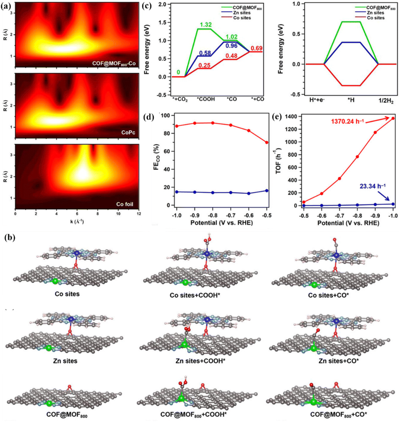 | ||
| Fig. 10 (a) WT-EXAFS. (b) Schematic mechanism. (c) Free energy of different active sites. (d) Partial current density. (e) TOF values. Reproduced with permission.76 Copyright 2023, Wiley-VCH. | ||
In addition to N and O heteroatoms, the doping of halogen atoms also affects ECO2RR activity.84 In order to reveal the effect of different halogen atom coordination on the performance of bimetallic catalysts, Ma et al. synthesized three different Cu–Cu sites by doping different halogens (I, Br, and Cl) into a Cu–Cu system.85 Different coordination can potentially affect the spacing of bimetallic sites (Fig. 11a), thus showing different catalytic reduction properties. Long-range Cu–I–Cu has a C2H4 Faraday efficiency of 36.54%, while short-range Cu–Cl–Cu has a FEC2H5OH of 32.69%. In general, the Faraday efficiency of C2+ products can be as high as 74.1% (Fig. 11b and c). As shown in Fig. 11d, the intrinsic activity of different coordination atoms is quite different. Due to the polarization of halogen atoms, the d-band center of I-coordinated Cu–I–Cu shifts to the right, and the binding ability with *CHO becomes weaker, thereby reducing the reaction energy barrier of C2H4. In addition, they also proposed a possible CO2RR mechanism (Fig. 11e). The protonation of the *CO intermediate is the rate-determining step. After interacting with Cu–I–Cu, it shows the lowest free energy and accelerates the coupling of C–C, promoting the deoxidation of *CH2CHO, thereby accelerating the formation of C2H4.
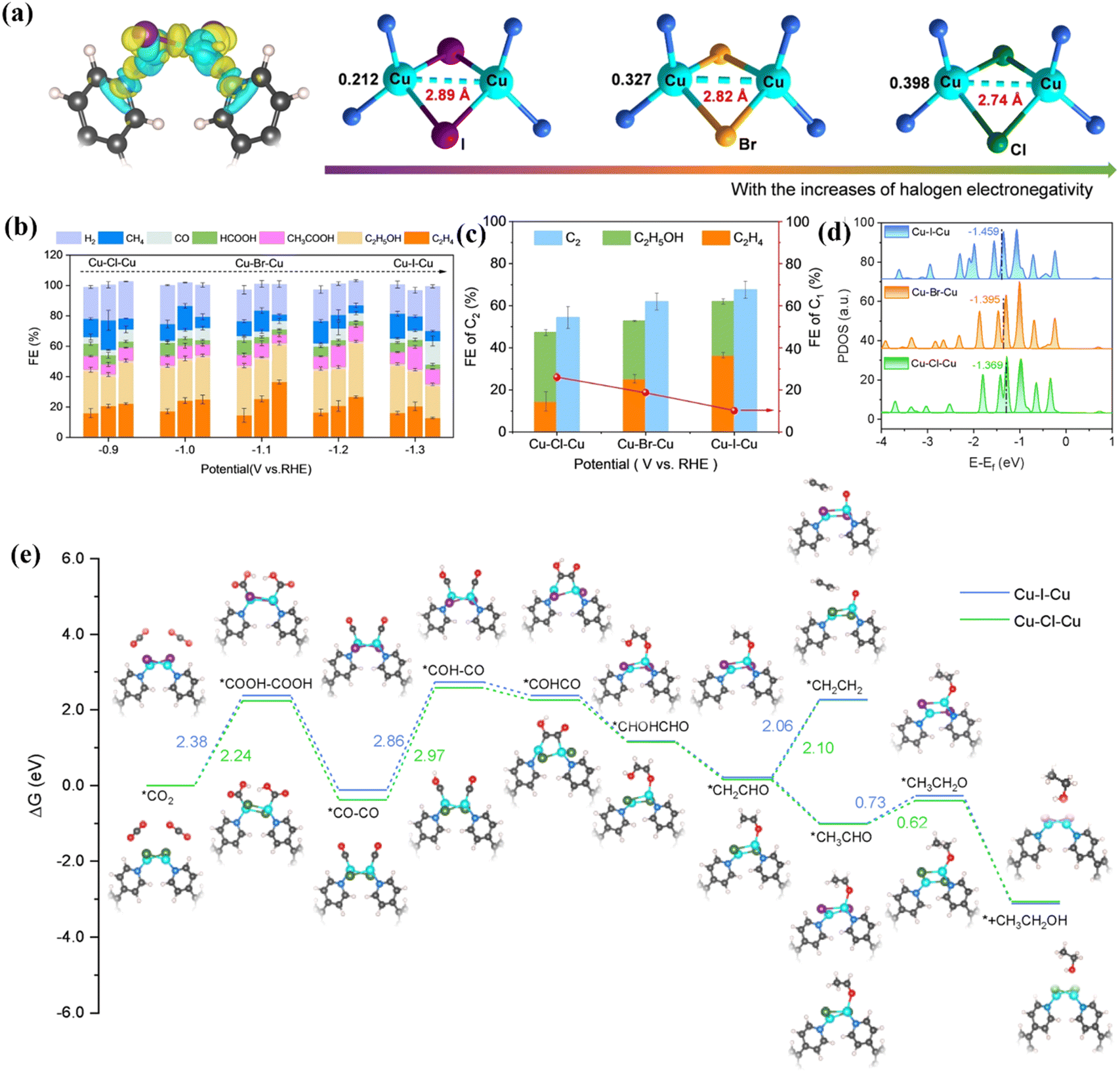 | ||
| Fig. 11 (a) Schematic diagram of different atomic coordination metal spacings. (b) FE of different products at different voltages. (c) FE of different products of different atom coordination catalysts. (d) DOS diagram of different atom coordination catalysts. (e) Reaction mechanism diagram. Reproduced with permission.85 Copyright 2024, Wiley-VCH. | ||
Efficient conversion of CO2 to C2+ can also be achieved by adjusting the metal coordination of the molecules in double-center metal complexes. Yang et al. pointed out that the double-center Cu complex formed clusters with high activity during electrolysis.86 The coordination environment of these complexes significantly affected the selective electrochemical stability of CO2RR. The structure of the three Cu complexes is shown in Fig. 12a, which is a double active center Cu complex composed of a ring expansion and a fluorinated porphyrin. The intramolecular tension and coordination asymmetry of the structure make the complex have more active copper centers. These centers can form copper clusters during the electrolysis process, accompanied by the partial reduction of O-containing six-membered heterocyclic ligands. This hybrid structure shows high efficiency in converting carbon dioxide into alcohols. At −1.2 V overpotential, the Faraday efficiency of ethanol is as high as 32.5%, the Faraday efficiency of n-propanol is 18.3% (Fig. 12b), and the total current density is maintained at about 9.4 mA cm−2. This is attributed to the synergistic effect between the inorganic phase and the organic phase, and the key intermediate *OCCOH can be stabilized in a confined space, thereby providing additional O–Cu bonding to promote C–C coupling (Fig. 12c).
 | ||
| Fig. 12 (a) Different configurations of Cu complexes. (b) FE of different products of Hex-2Cu–O at different voltages. (c) The schematic diagram of the C–C coupling mechanism on Hex-2Cu–O. Reproduced with permission.86 Copyright 2022, Springer Nature. | ||
3.4. Interface engineering
Accurate regulation of the surface and interface structure of bimetallic catalysts can improve and optimize the adsorption and desorption behaviour during the reduction process and greatly improve their selectivity and reduction activity, so as to achieve efficient conversion of CO2 into high value-added chemicals.78,87 A number of studies have shown that heterogeneous interfaces can be formed between different metal atoms, resulting in different synergistic effects and optimizing the catalytic activity of the materials.88 According to research, the combination of Zn and Sb can form a Zn–Sb bimetallic heterogeneous interface, which efficiently reduced CO2 to formate with a Faraday efficiency of 92%.89 This is attributed to the fact that the interaction between the two metals changes the electronic structure of the system, prompting electrons to shift from Zn to Sb, resulting in the d-band center of Sb moving down and reducing the energy barrier of the *OCHO reaction intermediate. In addition, Ning et al. constructed a SnO2/CuO heterogeneous interface on the surface of Cu–Sn by a two-step co-precipitation calcination method (Fig. 13a).90 Compared with SnO2 and CuO, SnO2/CuO NCs have a FEHCOOH of 89.3% at a voltage of −1.0 V and long-term stability for 30 h (Fig. 13b and c).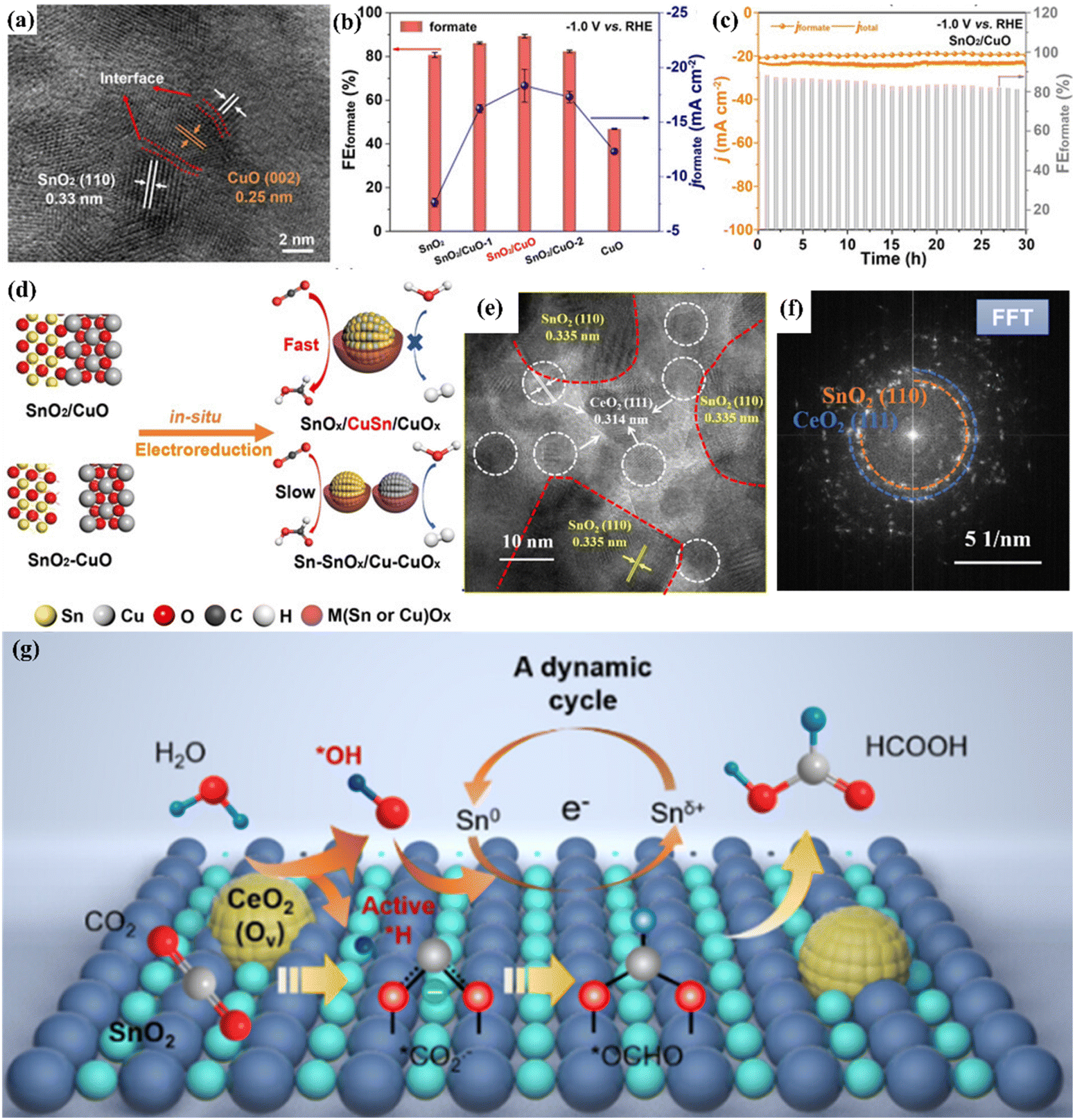 | ||
| Fig. 13 (a) TEM image. (b) FE of different catalysts. (c) Electrochemical stability. (d) The mechanism diagram of SnO2/CuO NCs. Reproduced with permission.90 Copyright 2021, European Chemical Societies Publishing. (e) FFT image. (f) HAADF-STEM image. (g) Mechanism diagram. Reproduced with permission.91 Copyright 2023, American Chemical Society. | ||
These excellent properties can be attributed to the in situ transformation caused by the heterogeneous interface of SnO2/CuO NCs, which can form a SnCu alloy and diversified active sites of SnOx/CuOx on the surface and effectively inhibit the HER process in CO2RR while enhancing the adsorption of the CO2− intermediate (Fig. 13d). In addition, the CeO2–SnO2 heterogeneous interface catalyst constructed by electrospinning technology can efficiently catalyze the formation of HCOOH and achieve a partial current density of 180 mA cm−2.91 At the same time, thanks to the special electronic environment provided by the heterogeneous interface, CeO2–SnO2 can operate stably for 53 h under electrolysis conditions, which is much longer than the stable time of SnO2 (13 h).The HAADF-STEM images showed that the CeO2–SnO2 interface was successfully constructed (Fig. 13e and f). They also proposed a cerium-mediated Sn0/Snδ+ redox reaction mechanism. The heterogeneous CeO2–SnO2 interface can reduce the dissociation energy of water. Among them, Ce4+ was reduced to Ce3+ during the electrolysis process, generating multiple oxygen vacancies, promoting water activation to generate *H and *OH. *H can exist stably on the heterogeneous interface, while *CO2− adsorbed on the surface combines with *H to form a *OCHO intermediate. At the same time, *OH can convert Sn0 to Snδ+ and maintain a high valence state in the system, resulting in formate formation (Fig. 13g).
The bimetallic heterogeneous interface is conducive to C–C coupling and can promote the electrocatalytic reaction of CO2 to generate C2+.93 Chen et al. found that the Cu0/Cu2+ heterogeneous interface constructed in the bimetallic Cu-based catalyst exhibited excellent interface stability and 90.9% FEC2H4 for CO2 electroreduction.42 The interfacial tunability of Cu affects the reaction energy barrier of the C–C coupling process. At the Cu0/Cu2+ interface derived from the CuPO catalyst, the Cu0 site can adsorb the *CO intermediate and the Cu2+ site promotes the hydrogenation of *CO to form *CHO (Fig. 14a), resulting in the low-energy coupling pathway of OC–CHO to accelerate the production of C2+. Similarly, Feng et al. in situ reconstructed the multiphase Ag/Cu/Cu2O bimetallic heterogeneous interface by doping Ag into a Cu-based MOF (HKUST-1) to promote the transformation of CO2 into C2H4 (Fig. 14b).92 The addition of Ag increases the *CO coverage on the Cu(I) surface, further promotes the C–C coupling and stabilizes the catalyst (Fig. 14c), thereby increasing the FE of C2H4. In addition to improving the FE of ethylene, CuAg bimetallic catalysts can also improve the FE of C2H5OH and C3H7OH through different surface and interface modifications. Gao et al. assembled a controllable Ag-based two-phase Ag–Cu heterostructure, which regulates product selectivity through kinetic recombination.43 There is a clear two-phase interface between Ag and Cu from the HAADF-STEM image (Fig. 14d). With an increase in Ag content, the main products are more inclined to generate alcohols (C2H5OH and n-C3H7OH). At a voltage of −1.05 V, the FE of alcohols can reach 44% (Fig. 14e). This is attributed to the fact that during the ECO2RR process, as the coverage of the *CO intermediate increases (Fig. 14f), Cu moves to the Ag surface (Fig. 14g) and surface reconstruction occurs, resulting in an Ag0.5–Cu0.5 interface. This will change the interfacial oxygen affinity and determine the final CO2 hydrogenation energy barrier, resulting in the formation of different products.
 | ||
| Fig. 14 (a) Schematic diagrams of different intermediates on different interfaces. Reproduced with permission.42 Copyright 2023, Springer Nature. (b) HR-TEM image. (c) In situ Raman spectra of different reaction times. Reproduced with permission.92 Copyright 2024, Royal Society of Chemistry. (d) HAADF-STEM image. (e) FE of different products on different interface structures. (f) The distribution of *CO concentration flux on the interface of different structures. (g) HAADF-STEM image and EDS of Ag0.5–Cu0.5. Reproduced with permission.43 Copyright 2024, Springer Nature. | ||
The bimetallic interface can achieve selective control of specific products by optimizing the adsorption properties of key intermediates. Huang et al. synthesized an Ag–Cu ND electrode with an adjustable structure by a colloidal chemical method.96 Compared with Ag NPs and Cu NPs, Ag–Cu NDs exhibited ultra-high CO2 reduction activity. The FEC2H4 of Ag–Cu NDs is 3.4 times that of Cu NPs, and the current density at −1.1 V is 2 times that of Cu NPs. Due to the introduction of Ag atoms into the Cu system in the form of separated nanodomains, the electrons of Cu move. The electron-deficient Cu binds to CO at the interface and promotes the coupling of CO. At the same time, the domain interface of Cu can regulate the oxidation state of Cu, which can promote the dimerization of CO–CO to the greatest extent. Wang et al. modified Ag on the surface of cubic Cu2O and activated it by electrochemical reduction to regulate the valence state and coordination number of Cu sites on the catalyst surface. The FE of the final target product CH3CH2OH was 40.8% (Fig. 15a).94 TEM and HRTEM images showed that there is an Ag modified Cu2O heterogeneous interface in Cu2O/Ag NC (Fig. 15b and c). Compared with a pure Cu catalyst, *CO exists on the surface of the dCu2O/Ag2.3% catalyst in the mode of top adsorption and bridge adsorption. The process of protonation of *CO adsorbed on the Cu site to produce *CHO or *COH intermediates is more likely to occur. After that, the asymmetric *CO–*CHO (*COH) coupling with the top-adsorbed *CO is more inclined to generate C2+ products (Fig. 15d). At the same time, the asymmetric C–C coupling leads to the destruction of the originally balanced coordination environment at the Cu site, making it easier to stabilize the more saturated ethanol intermediate *OC2H5.
 | ||
| Fig. 15 (a) The synthesis roadmap of Cu2O/Ag. (b) TEM image. (c) HRTEM image. (d) The reaction mechanism diagram on Cu2O/Ag2.3%. Reproduced with permission.94 Copyright 2022, Springer Nature. (e) The charge density at the Cu/CuNC interface. (f) C–C coupling process at the Cu/CuNC interface. Reproduced with permission.95 Copyright 2022, Oxford University Press. | ||
The interaction and constraint between specific metal atoms can be realized by finely manipulating the surface interface of the catalyst at the atomic level, which can effectively promote the CO2RR process. Yang et al. constructed the interface sites of an electronic asymmetric structure at the Cu/CuNC interface by an in situ electrochemical reduction method (Fig. 15e).95 ER-Cu/CuNC can efficiently reduce CO2 to C2+ products with an FE of 60.3% at a low potential of −0.35 V and operate stably for 6 h. This site can increase *CO adsorption, significantly reducing the kinetic barrier of *CO-*CHO (C–C) coupling (0.30 eV) (Fig. 15f).
3.5. Strain engineering
Strain engineering is mainly divided into tensile strain and compressive strain.97 Strain engineering is mainly to change the lattice structure of a material through the interaction between atoms and induce lattice strain, which leads to the change of lattice parameters.98 This change will significantly affect the distance and arrangement between atoms and then change the energy band structure of electrons, including the width of the energy band, the size of the energy gap and the position of the Fermi level.99,100 In recent years, strain engineering has been introduced into the CO2RR process. In this process, it mainly affects the adsorption, activation and desorption process of the reactants, by changing the electron density and geometric environment of the active sites, and effectively regulates the catalytic activity and selectivity of the materials.101 Specifically, the strain will change the d-band center position of the metal atoms in the catalyst, thereby optimizing the adsorption and activation of the catalyst surface and enhancing the stability while improving the reduction efficiency. Clark et al. prepared a CuAg electrode by mixing Cu and Ag in a vacuum arc furnace.102 The introduction of Ag secondary metal will form a CuAg surface alloy, which in turn causes compressive strain on the Cu surface. This change in the surface structure increases the binding energy of the valence band density, thereby reducing the adsorption energy of H, and can increase the FE of the C2+ product by 10–15% while weakening the HER activity by 60–75%. In addition, lanthanide metals (LMs) have a unique 4f electronic structure and 5d orbital, and there is spontaneous spin–orbit coupling. The larger metal ion radius will cause tensile strain, which is helpful to optimize the binding energy of key intermediates. Feng et al. doped single atom Gd in a Cu2O system to prepare a Gd1/CuOx catalyst.103 In this, Gd is connected to 5 O atoms with an average bond length of 2.40 Å, which is different from the bond length of Cu–O (1.85 Å) (Fig. 16a and b), thus inducing the tensile strain of CuOx. When the strain degree of the whole reaction system changes from 0% to 2.5% (Fig. 16c), the free energy of 2*CO-to-O*CCO decreases by 0.3 eV (Fig. 16d), 81.3% FEC2+ is achieved at −0.8 V and the electrochemical stability is more than 40 h (Fig. 16e). | ||
| Fig. 16 (a) EXAFS diagram of Gd in Gd1/CuOx. (b) Cu K-edge FT EXAFS. (c) Different degrees of strain. (d) Free energy. (e) FE. Reproduced with permission.103 Copyright 2023, American Chemical Society. | ||
It is worth noting that the strain effect easily occurs in shell–core structure catalysts. Due to the mismatch between the core and the shell, lattice strains such as compressive strain or tensile strain will be triggered, thereby adjusting the electronic structure around the metal atom and optimizing its catalytic activity. Zhu et al. prepared a core–shell bimetallic catalyst for CO conversion by coating an ultrathin palladium-rich shell on the outer layer of a Au–Pd alloy (Fig. 17a).104 DFT calculation results showed that when the Au content increases to a certain extent, the lattice structure expands due to the difference in the atomic radius, which leads to the tensile strain of the Pd shell. This strain causes the d-band center of the Pd atom to move up, thereby enhancing the adsorption of *COOH. In addition, there is O coordination on the surface of the catalyst, which also synergistically stabilizes the adsorption of *COOH. Similarly, Wang et al. prepared Pd–Au nanowires with a unique shell–core structure (Fig. 17b).105 Due to the tensile strain effect, Pd0.8Au@Pd has a strong adsorption of the *COOH intermediate, resulting in 94.3% FECO (Fig. 17c and d). Interestingly, the heterostructure also induces atomic tensile strain. The introduction of In into Cu-based catalysts to construct an In2O3/Cu heterojunction can induce tensile strain of Cu (Fig. 17e and f).106 The presence of heterojunctions contributes to the regulation of the electronic structure and effective adsorption of CO2. The tensile strain increases the adsorption of *HCOO and thus improves the product selectivity of HCOOH (Fig. 17g and h).
 | ||
| Fig. 17 (a) Colored HAADF image. Reproduced with permission.104 Copyright 2019, Royal Society of Chemistry. (b) Colored HAADF image. (c) FE image. (d) The adsorption diagram of *COOH on the surface of different catalysts. Reproduced with permission.105 Copyright 2018, Wiley-VCH. (e) A schematic diagram of the heterostructure of In2O3/Cu. (f) Tensile strain diagram. (g) ΔG diagram of CO. (h) ΔG diagram of HCOOH. Reproduced with permission.106 Copyright 2023, Elsevier Ltd. (i) The strain recombination diagram of Sn–CuO-7.5. Reproduced with permission.107 Copyright 2023, American Chemical Society. | ||
In addition, the compressive strain and the tensile strain can be converted to each other to maximize the catalytic efficiency. Wei et al. prepared a Sn-doped Sn–CuO-7.5 catalyst by the hydrothermal method.107 CuO will be reduced to Cu at an applied voltage of −0.6 V. With the introduction of Sn atoms, the lattice spacing of Sn/Cu will be expanded. Specifically, during the CO2RR process, Sn–CuO-7.5 underwent in situ reconstruction, transforming from compressive strain into tensile strain to accelerate the production of CO (Fig. 17i). The Cu of Sn/Cu acts as the active site of the reaction, and Sn regulates the electronic structure around Cu. Under their synergistic effect, 95.5% FECO can be achieved.
It is worth noting that strain engineering may lead to relaxation behaviour during the reaction process, which may lead to changes in the surface structure of a catalyst, thereby affecting the catalytic activity. Studies have shown that high temperature-induced strain relaxation can achieve controllable lattice strain of bimetallic catalysts. This strain relaxation can improve the conversion activity of the catalyst, thereby improving the Faraday efficiency of the reduction product. Hao et al. coordinated Pd(Ag,Au)/Ni bimetallic precursors with polyvinylpyrrolidone (PVP) and then prepared s-Pd(Ag,Au)Ni/CNF by electrospinning technology (Fig. 18a).108 The IFFT diagram shows that the lattice spacing of d(111) and d(200) s-PdNi NP is 2.22 Å and 2.11 Å, respectively, which is larger than the standard spacing (2.17 Å and 1.88 Å), indicating that different degrees of tensile strain have appeared (Fig. 18b). At 400 °C, s-PdNi/CNF-400 exhibited the largest strain (6.1%). When the temperature began to increase, s-PdNi NPs began to show strain relaxation. When the temperature increases to 1000 °C, the strain decreases to 2.3%. Under electrolysis conditions, the strain-relaxed s-PdNi/CNF-1000 exhibited the largest FECO (96.6%) and the largest partial current density (−12 mA cm−2) at −0.88 V (Fig. 18c). DFT calculation results showed that after strain relaxation at high temperature, the s-PdNi-2.3% surface has a more negative *COOH free energy, which promotes the formation of *COOH and *CO, thereby improving the reactivity of CO2RR (Fig. 18d and e). In summary, the strain relaxation induced by thermodynamics will improve the catalytic performance of bimetallic catalysts for CO2RR.
 | ||
| Fig. 18 (a) The synthesis roadmap of s-PdNi NP. (b) IFFT image. (c) FE. (d) The reaction mechanism diagram. (e) Free energy. Reproduced with permission.108 Copyright 2022, American Chemical Society. | ||
4. Advantages of bimetallic catalysts
The combination of double metal elements can introduce new active sites and catalytic mechanisms for electrocatalytic reactions, greatly improving the catalytic activity. A single metal catalyst faces many limitations. The introduction of a second metal can break the original limitations and effectively enhance the adsorption of CO2 in the CO2RR process. Through the electronic and geometric effects between the two metals, the CO2RR activity can be significantly improved.4.1. Enhancing CO2 adsorption capacity
The active sites of traditional single metal catalysts are relatively unitary, and the CO2 adsorption capacity is weak.109,110 Therefore, it is particularly important to explore catalysts with multiple active sites for the CO2RR. Bimetallic catalysts can optimize the electron density of the metal active center through electron transfer and enhance their adsorption capacity for CO2 molecules.111,112 The CO2 adsorption behaviour usually occurs on the catalyst surface, and the construction of active sites at the bimetallic interface is particularly important. Sun et al. synthesized an MOF-mediated Ag-modified copper oxide bimetallic catalyst (CuO/Ag@C).113 The material exhibits a layered structure, while bimetallic nanoparticles are encapsulated in porous carbon and there is a heterogeneous interface (Fig. 19a). DFT-assisted calculations showed that the surface adsorption energy of the Ag–Ag/Cu(111) interface is −0.08 eV, which is higher than that of the Cu heterogeneous interface and pure Cu interface (Fig. 19b). This indicates that the bimetallic catalyst has stronger CO2 adsorption capacity. Similarly, Meng et al. studied the CO2 adsorption performance of bimetallic Cu/Zn,114 which can adsorb a large amount of CO2 and reduce it to the *CO intermediate under the combined action of bimetals. Due to the weak binding energy of Zn, *CO migrates, making the Cu surface highly covered with *CO, thereby promoting C–C coupling, generating ethylene and ethanol while inhibiting the HER (Fig. 19c). In addition, In/Bi-750 synthesized by Wang et al. on a two-dimensional substrate can in situ form bimetallic active sites of the InBi alloy under the action of electrolysis (Fig. 19d).115 DFT calculations showed that the BiIn(111) site has a strong adsorption capacity for CO2 and can generate intermediates.
  reacts with protons and electrons to form OCHO and OCHO. In addition, the Bi and In sites on the BiIn(111) interface have a lower reaction energy barrier, and the binding energy of the reaction process can be optimized by the synergistic effect of the bimetallic catalyst, thereby promoting the reaction (Fig. 19e). Among them, the introduction of Bi atoms makes the p-band of the system move down (Fig. 19f). The above behaviour effectively regulates the adsorption of CO2 and promotes the maximization of FEHCOOH.
 | ||
| Fig. 19 (a) HRTEM image. (b) The adsorption energy of *CO2 on the surface of different catalysts. Reproduced with permission.113 Copyright 2024, Elsevier Ltd. (c) The reaction mechanism diagram on CuZn/GDE. Reproduced with permission.114 Copyright 2024, Elsevier Ltd. (d) A schematic diagram of atomic movement under electrolysis conditions. (e) The free energy diagrams of HCOOH on different interfaces. (f) PDOS image. Reproduced with permission.115 Copyright 2023, Wiley-VCH. | ||
4.2. Adjusting the reaction energy barrier
In the CO2RR process, lowering reaction energy barriers of intermediates by adjusting the surface dispersion of catalysts has a great influence on the product selectivity.116 Bimetallic catalysts can optimize the electronic structure of the catalyst surface by introducing secondary metals, thereby improving the adsorption and desorption capacity of the intermediates. Zhao et al. regulated the reaction energy barriers of key intermediates by dispersing strongly bound metal In on the surface of weakly bound metal Zn, which effectively promoted the conversion of CO2 to HCOO− (Fig. 20a).117 The In–Zn interface (In–Zn2) forms active sites through favourable orbital interactions, thereby achieving efficient HCOO− conversion. The results of in situ FT-IR and DFT calculations showed that the In–Zn2 interface is more favourable for the adsorption and activation of CO2 (Fig. 20b and c) and can effectively reduce the reaction energy barrier of *OCHO (Fig. 20d and e), thereby affecting the production of HCOO−. In addition, Li et al. proved that the introduction of Ga atoms in Cu-based catalysts can induce the hybridization of p–d orbitals (Fig. 20f).118 The hybridization of p–d can enrich the reactive sites to a certain extent, which is beneficial to improve the binding strength of *CO (Fig. 20g), thus accelerating the C–C coupling process. At a current density of 0.9 A cm−2, 81.5% of FEC2+ is exhibited (Fig. 20h).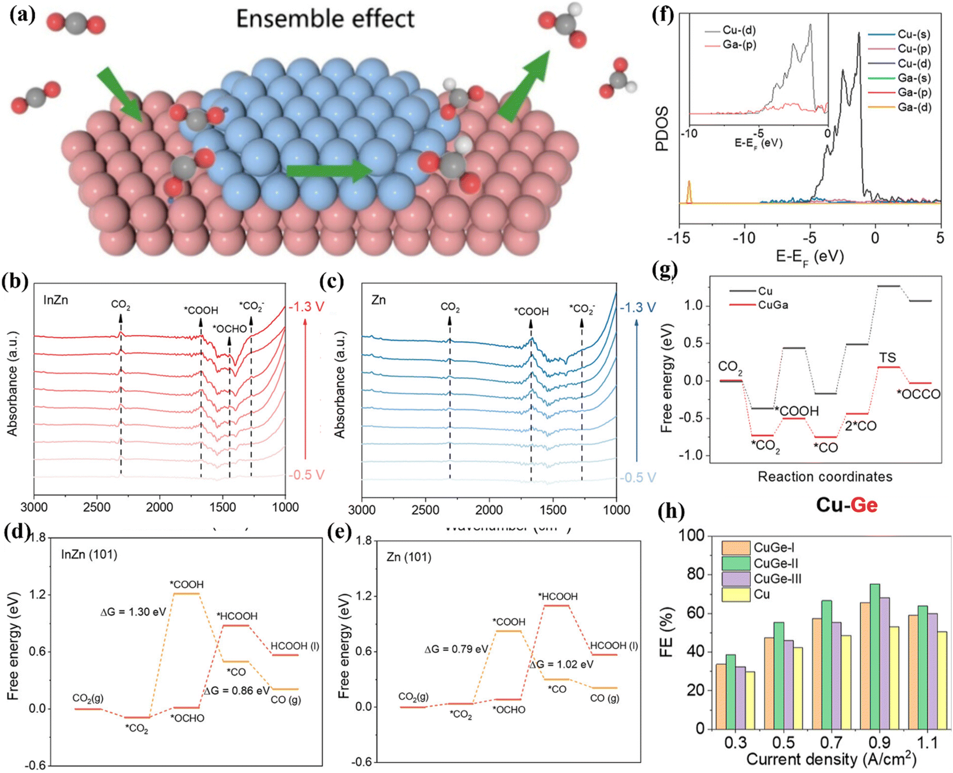 | ||
| Fig. 20 (a) The action diagram. (b) Raman spectra of In–Zn2. (c) Raman spectra of Zn/ZnO. (d and e) Free energy diagrams on different surface structures. Reproduced with permission.117 Copyright 2024, American Chemical Society. (f) PDOS image. (g) Free energy diagrams. (h) FE image. Reproduced with permission.118 Copyright 2023, American Chemical Society. | ||
The adsorption of active sites on different reaction intermediates leads to different reaction pathways and the formation of final products. The different interactions between the two metals in bimetallic catalysts have a key effect on the binding energy of intermediates. Huang et al. synthesized a CuxSb alloy by a high temperature solid phase method and found that the selectivity of the CO product was closely related to the molar ratio of Cu and Sb.119 When the molar ratio of Cu and Sb is 3![[thin space (1/6-em)]](https://www.rsc.org/images/entities/char_2009.gif) :1, it shows the largest FECO (Fig. 21a). The results of EXAFS showed that there are Cu–Sb metal bonds in the system (Fig. 21b). As the molar ratio of Cu atoms increases, Sb will be surrounded by more Cu atoms, making the Cu–Sb bond stronger. Under the action of applied voltage, the bonding strength between *COOH and the material becomes larger (Fig. 21c) and the CO selectivity is improved. In addition, Zhang et al. constructed Cu–Pd dimer sites in MOFs to study the ECO2RR activity, aiming to improve the FECO.120 They used the ion exchange method to introduce Pd into the Cu–Pd paddle wheel node structure to induce the reconstruction of the pore structure. HP-2 presents a Cu core and an octahedral core–shell structure with Pd/Cu as the shell (Fig. 21d), which has a specific surface area of 1474 m2 g−1. HP-2 achieves a maximum FECO of 85% at −0.77 V vs. RHE (Fig. 21e). XAFS confirmed that the coordination environment of Pd did not change significantly under in situ conditions (Fig. 21f). DFT calculations revealed the key role of Pd atoms in enhancing CO selectivity (Fig. 21g) and Cu as the main active site for the CO2RR (Fig. 21h). The introduced Pd atom affects the d-band center of the adjacent copper site, reduces the electron filling of the anti-bond (d–σ)* orbital (Fig. 21i and j), effectively enhances the adsorption strength of *COOH on the Cu site, and finally reduces the energy barrier of CO2RR.
:1, it shows the largest FECO (Fig. 21a). The results of EXAFS showed that there are Cu–Sb metal bonds in the system (Fig. 21b). As the molar ratio of Cu atoms increases, Sb will be surrounded by more Cu atoms, making the Cu–Sb bond stronger. Under the action of applied voltage, the bonding strength between *COOH and the material becomes larger (Fig. 21c) and the CO selectivity is improved. In addition, Zhang et al. constructed Cu–Pd dimer sites in MOFs to study the ECO2RR activity, aiming to improve the FECO.120 They used the ion exchange method to introduce Pd into the Cu–Pd paddle wheel node structure to induce the reconstruction of the pore structure. HP-2 presents a Cu core and an octahedral core–shell structure with Pd/Cu as the shell (Fig. 21d), which has a specific surface area of 1474 m2 g−1. HP-2 achieves a maximum FECO of 85% at −0.77 V vs. RHE (Fig. 21e). XAFS confirmed that the coordination environment of Pd did not change significantly under in situ conditions (Fig. 21f). DFT calculations revealed the key role of Pd atoms in enhancing CO selectivity (Fig. 21g) and Cu as the main active site for the CO2RR (Fig. 21h). The introduced Pd atom affects the d-band center of the adjacent copper site, reduces the electron filling of the anti-bond (d–σ)* orbital (Fig. 21i and j), effectively enhances the adsorption strength of *COOH on the Cu site, and finally reduces the energy barrier of CO2RR.
 | ||
| Fig. 21 (a) The synthesis diagram of CuxSn. (b) EXAFS. (c) Raman spectra of Cu3Sn. Reproduced with permission.119 Copyright 2024, American Chemical Society. (d) SEM image of HP-2. (e) FE image. (f) XAFS. (g) Free energy diagrams. (h) The schematic diagram of Cu sites in Cu–Pd. (i and j) PDOS. Reproduced with permission.120 Copyright 2024, Wiley-VCH. | ||
4.3. Synergistic effect
In a bimetallic catalytic system, metal atoms can promote the activation and conversion of reactants through electron redistribution, the steric hindrance effect and synergistic enhancement of active sites, so as to achieve better catalytic activity than single metal catalysts.121 The synergistic effect of bimetallic catalysts is reflected in many aspects, including the electronic structure, geometric configuration, active site characteristics and dynamic processes. These mechanisms together improve the overall performance of the catalysts. For example, Wen et al. developed Sn nanosheets modified with Bi atoms to study the conversion of CO2 into HCOOH.122 The electroreduction process mainly involves *COOH and HCOO* intermediates. HCOO* has a larger adsorption energy (0.81 eV) on the surface of Bi–Sn (Fig. 22a), and Bi–Sn shows a strong interaction. In addition, when the secondary metal is introduced, the Fermi levels of p and d of Sn shift up (Fig. 22b), which makes the HCOO* intermediate adsorbed on the surface more stable and promotes the formic acid production process. In another report, Hao et al. developed a CuNi-DSA/CNFs catalyst by electrospinning technology (Fig. 22c).123 Under the synergistic effect of CuN4–NiN4 sites, it is easier to form the *COOH intermediate. Similarly, Tan et al. proposed that the strong interaction between In–Bi induced by In can reconstruct the electrons in the local region, thereby increasing the conversion of CO2 to formate.126 Xu et al. confirmed that the Co–Ni bimetallic catalyst synthesized by self-assembly doping Al2O3 has excellent methane selectivity.124 The synergistic effect between Co and Ni can regulate the activation process of H and CO2, which can effectively improve the selectivity. Specifically, the Ni site mainly adsorbs and dissociates H2, while the Co site is responsible for the adsorption and activation of CO2 (Fig. 22d). After that, H is transferred from the Ni site to the Co site and combines with the intermediate to form CH4. Park et al. synthesized a Au–Ag alloy by the galvanic replacement method.125 This alloy exhibits a hollow cube structure with a large active specific surface area (Fig. 22e). The C atom in the key intermediate *COOH is adsorbed by Au, and O is adsorbed by Ag, which maximizes the intrinsic activity under the synergistic effect of bimetallic sites (Fig. 22f). | ||
| Fig. 22 (a) Free energy diagrams. (b) PDOS. Reproduced with permission.122 Copyright 2018, Wiley-VCH. (c) The synthesis diagram of CuNi-DSA/CNFs. Reproduced with permission.123 Copyright 2022, Wiley-VCH. (d) The synergistic catalytic mechanism of bimetallic Cu–Ni. Reproduced with permission.124 Copyright 2018, Elsevier Ltd. (e) TEM image. (f) The synergistic catalytic mechanism of Au1Ag1. Reproduced with permission.125 Copyright 2022, American Chemical Society. | ||
5. Typical bimetallic catalysts for the ECO2RR
In recent years, with the aggravation of environmental problems, researchers have carried out in-depth research in the field of ECO2RR. With the further development of science and technology, great progress has been made in ECO2RR. Here, we divide the catalysts with the most ECO2RR ability into diatomic catalysts (DACs), alloy catalysts, MOF-based catalysts and COF-based catalysts, and systematically summarize their unique electrochemical properties. In addition, we also provide a summary comparison table of ECO2RR parameters, including FEs, current densities, applied potentials, electrolytes and devices aiming to provide researchers with more cutting-edge data comparison and design ideas (Table 2).| Catalyst | FE (%) | Current density (mA cm−2) | Applied potential (V vs. RHE) | Electrolyte | Device | Ref. |
|---|---|---|---|---|---|---|
| Cu98Pd2 | C2+ (75.6%) | −200 | −1.15 | 1 M KCl | Flow cell | 127 |
| Bi–Pb/CP | HCOOH (97.8%) | 53.1 | −0.8 | 0.5 M KHCO3 | H-cell | 128 |
| Pb7In3 | HCOOH (91.6%) | −17 | −1.26 | 0.5 M KHCO3 | H-cell | 129 |
| BiInO-0.67@C | HCOOH (91%) | — | −0.9 | 0.5 M KHCO3 | H-cell | 130 |
| CoCu3/CFs | C1 (97%) | 78.1 | −0.8 | 0.5 M KHCO3 | H-cell | 131 |
| Mg–Cu | C2+ (≥80%) | −1000 | −0.77 | 1 M KOH | Flow cell | 132 |
| ZnCuO-500 | C2H4 (45%) | 200 | −1.0 | 1 M KOH | Flow cell | 133 |
| Cu0.543Ni1/NC | CO (99.7%) | — | −0.6 | 0.1 M KHCO3 | H-cell | 134 |
| R-Cu/Au | C3H7OH (46.6%) | 124 | −0.78 | 1 M KOH | Flow cell | 135 |
| Ni/Fe–N–C | CO (98%) | — | −0.7 | 0.5 M KHCO3 | H-cell | 136 |
| CuAg-0.75% | C2H5OH (21.0%) | 214.4 | −0.71 | 1 M KOH | Flow cell | 137 |
| Cu5Zn8 | C2H5OH (46.6%) | 2.3 | −0.8 | 0.1 M KHCO3 | H-cell | 138 |
| Cu3N–Ag | C2H4 (38%) | 26.7 | −1.0 | 1 M KOH | Flow cell | 139 |
| CuO/ZnO/C | C2H4 (50.9%) | 367 | −0.75 | 1 M KOH | Flow cell | 140 |
5.1. Diatomic catalysts
DACs are widely used in electrochemical CO2 reduction due to their dual active sites.141,142 The synergistic effect of bimetallic sites can give the catalysts excellent performance, promote the coupling of C–C bonds, and thus achieve effective reduction of CO2.143 DACs can break the limitation of the scaling relationship of single-atom catalysts and achieve the synergistic effect of multiple active sites. DACs can be divided into homonuclear DACs and heteronuclear DACs.144 Heteronuclear diatomic metal sites can be connected by atoms such as O/N/S and dispersed on the surface of the carrier framework. Among them, the metal–metal interaction in heteronuclear DACs can optimize the electronic structure of active sites and promote the kinetic process of CO2RR. Theoretical studies have shown that CuCr/C2N sites are designed by embedding heterogeneous transition metal binary components on the surface of single-layer C2N, which can efficiently reduce CO2 to methane at low potentials.145 Similarly, the incorporation of N-doped Pd–Zn diatomic sites on an ordered mesoporous carbon surface helps to further enhance CO selectivity (Fig. 23a).146 The average spacing of Pd–Zn was 2.46 Å, which confirmed the successful synthesis of Pd–Zn diatomic sites. The turnover frequency (TOF) is 14633 h−1 at −0.72 V and the FECO is 97.14% (Fig. 23b and c). In addition, it showed a partial current density of 11.12 mA cm−2 and a long-term stability of 30 h. The Pd 3d and Zn 3d orbitals in PdZnN6 can undergo d–d orbital coupling near the Fermi level (Fig. 23d). The quasi-covalent Pd–Zn bond in the system induces the rearrangement of Pd 3d orbital energy levels and electrons (Fig. 23e), which helps reduce the adsorption energy of *COOH intermediates and promote the formation of CO molecules.
 | ||
| Fig. 23 (a) The synthesis roadmap of N-CMK-3-D. (b) TOF. (c) FE. (d) PDOS. (e) Density difference of different catalytic sites. Reproduced with permission.146 Copyright 2024, Elsevier Ltd. (f) XANES. (g) The structure model of Cu–S–Ni/SNC. Reproduced with permission.147 Copyright 2024, Wiley-VCH. | ||
In addition, heteroatom doping can further improve the catalytic activity of diatomic catalysts for CO2RR to a certain extent.148,149 This improvement is mainly due to the synergistic effect of heteroatom doping and the optimization of the catalyst structure. For example, Sun et al. found that the asymmetric coordination Cu–S–Ni/SNC synthesized using wool keratin exhibited higher reduction activity than sulfur-free doped CuNi bimetallic catalysts in the production of CO.147 Specifically, Cu–S–Ni/SNC has 98.1% FECO at a low potential of −0.65 V. Wool keratin contains multiple disulfide bonds, which can introduce S onto the surface of the material. At the same time, the long-range ordered protein structure can provide regular metal active sites. XAS analysis results showed that both Cu and Ni show positive valence states, and the valence states shift with the incorporation of S atoms (Fig. 23f). In addition, the Cu K edge confirms that N2Cu–S–NiN2 is the optimal structure for CO production (Fig. 23g). DFT calculations further confirmed the above statement. CO2 is first adsorbed on the surface of the two metal atoms, forming *COOH through the CPET process, and *COOH can be further protonated to form the CO* intermediate. Finally, CO* is desorbed from the diatomic surface to form CO (Fig. 24a). The asymmetric structure of N2Cu–S–NiN2 exhibits a low reaction energy barrier of 0.3107 eV. DOS analysis showed that the Ni atom site has a strong adsorption capacity, and the S atom can regulate the production of *COOH (Fig. 24b). Therefore, the Cu site is dually regulated by the S and Ni sites, which helps enhance CO2 adsorption and CO desorption, thereby maintaining the highest CO selectivity.
 | ||
| Fig. 24 (a) Reaction mechanism. (b) DOS. Reproduced with permission.147 Copyright 2024, Wiley-VCH. (c) In situ CV. (d) Cu concentration distribution. Reproduced with permission.150 Copyright 2022, Elsevier Ltd. (e) The d-band center diagram of different catalyst surfaces. Reproduced with permission.138 Copyright 2020, Elsevier Ltd. (f) Structural schematic diagram of Bi1Pd15(111)-SAA. (g) Free energy diagram. Reproduced with permission.151 Copyright 2020, Elsevier Ltd. | ||
5.2. Bimetallic alloys
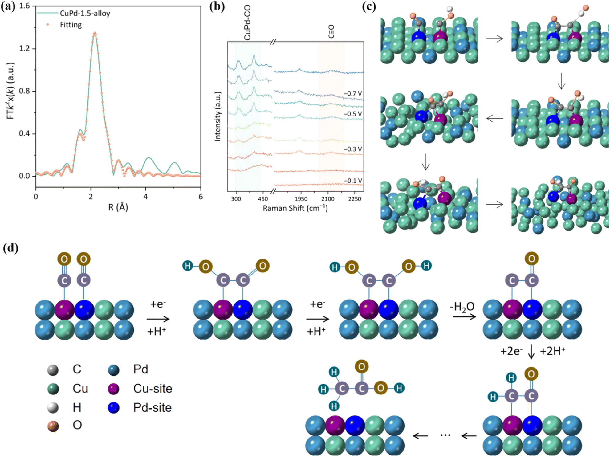
Nowadays, bimetallic alloy catalysts have gradually become promising catalysts for efficient electrocatalytic reduction of CO2.152 The two metal centers in bimetallic alloys can produce a synergistic effect through electron transfer, geometric deformation and surface recombination to form unique active centers. This synergistic effect reduces the energy barrier of the reaction, improves the activation efficiency of CO2 molecules, and promotes key steps such as C–C coupling, thereby accelerating the rate of CO2 reduction.153 The electronic structure of the two metals in the alloy state will change, resulting in the electron density distribution on the metal surface being different from that of the pure metal, thus changing the energy and selectivity of CO2 adsorption. In addition, bimetallic alloy catalysts support a variety of reaction mechanisms, so that CO2RR can be carried out through different reaction paths, which helps form various products such as CO, HCOOH and CH3OH.154 Wang et al. prepared np-AgCu by the chemical dealloying method, which showed a copper-rich interface and had a high selectivity to CO with a Faraday efficiency of 97.5%.150 The results of in situ cyclic voltammetry (CV) analysis showed that the integral ratio of the area of the anodic oxidation peak to the total charge increased by 4 times after 3 hours of reaction, and the Cu concentration on the surface of np-AgCu also increased, which means that the surface reconstruction of Cu occurred during the electrochemical process, which promoted the adsorption of CO2 (Fig. 24c and d). Similarly, the Cu/Zn alloy prepared by doping Zn in Cu also showed high *CO formation activity. With the strong binding of Cu and Zn, the d-band center of Cu changes, which reduces the binding ability of H and increases the adsorption of *CO while inhibiting the HER (Fig. 24e).Xie et al. reported that Bi6Pd94-SAA NDs can continuously perform CO2RR for more than 20 h at −0.4 V to −0.5 V vs. RHE.151 This is due to the introduction of Bi in Bi6Pd94-SAA NDs, which reduces the H content on the surface and weakens the affinity between Pb and H, thus reducing the reaction energy barrier of the *COOH intermediate and promoting the desorption of formate (Fig. 24f and g). It is exciting to note that the CuO–PMA co-assembled sub-nanosheets can in situ form a CuPd alloy under entropy-driven conditions, which can efficiently produce acetate with FE up to 46.5 ± 2.1%.155 Among them, CuPd-1.5 exhibits a single crystal structure. During the alloying process, Cu atoms are gradually reduced from Cu(II) to Cu(I)/Cu(0). EXAFS showed that the bond length of Cu–Pd is about 2.15 Å (Fig. 25a). Furthermore, the wavelet transform (WT) showed that the structure of Cu–Pd is highly ordered and alternately arranged in the alloy. In situ Raman spectroscopy showed that the CuPd-1.5 alloy can enhance the adsorption of *CO intermediates (Fig. 25b). AIMD simulation results showed that the high vibration characteristics of Cu and Pd atoms make the adsorbed CO and COH close to each other and the coupling reaction occurs (Fig. 25c). Specifically, the *CO generated at the Pd site moves to the Cu site through the overflow effect to complete the C–C coupling, thereby generating acetic acid (Fig. 25d).
 | ||
| Fig. 25 (a) Pd K-edge EXAFS. (b) Raman spectra. (c) AIMD simulation diagram. (d) Reaction mechanism diagram. Reproduced with permission.155 Copyright 2024, American Chemical Society. | ||
5.3. Bimetallic MOFs
Porous carbon materials have adjustable pore structures and high specific surface area, which can provide multiple surface active sites, which is conducive to the surface adsorption and diffusion of CO2 molecules.156,157 The excellent electrical conductivity and chemical stability further promote the application of porous carbon materials in the field of electrocatalytic carbon dioxide reduction. The frameworks are stable structures composed of metal centers and organic ligands connected by covalent bonds or coordination bonds.158–160 MOFs are good precursor templates, which can be converted into nitrogen-rich porous carbon during pyrolysis.161 However, porous carbon has low reactivity for the CO2RR, and additional metal elements (such as Cu, Ni and Bi) need to be added to the system to improve its catalytic performance.162,163 The introduction of two metal atoms can produce a synergistic effect, generate synergistic active centers, optimize the electronic structure, and greatly enhance the adsorption and activation of CO2. The atomic structure of bimetallic MOFs is more conducive to the research and exploration of the reaction mechanism.164 The introduction of In into Ga-MOF by ion exchange technology contributes to the movement of charge, thereby achieving 93% FEHCOOH (Fig. 26a).165 InGa-MOF has a specific surface area of 1509 m2 g−1 (Fig. 26b), which contributes to the adsorption of CO2. Due to the difference in electronegativity between the two metals, the electrons around In move to O (C–O–M) to redistribute the charge. After this process, In is seriously deficient in electrons, thereby enhancing the interaction between p–d orbitals and increasing the adsorption of *OCHO intermediates (Fig. 26c and d).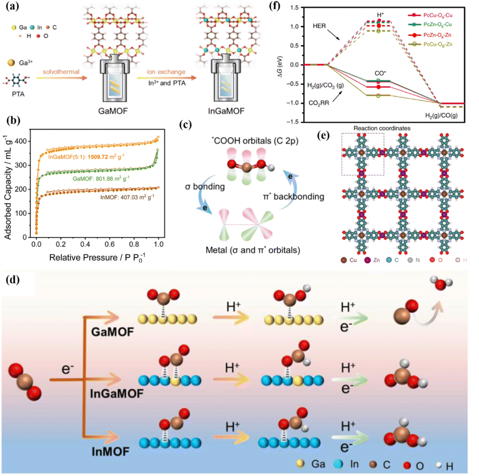 | ||
| Fig. 26 (a) The synthesis of InGa-MOF. (b) N2 adsorption–desorption curves. (c) The interaction between *COOH and intermetal orbitals. (d) Reaction mechanism diagram. Reproduced with permission.165 Copyright 2024, Royal Society of Chemistry. (e) The spatial structure diagram of PcCu–O8–Zn. (f) Free energy diagram. Reproduced with permission.39 Copyright 2020, Springer Nature. | ||
Another study showed that two-dimensional bimetallic MOFs (PcCu–O8–Zn) connected by CuN4 and zinc-bis (dihydroxy) complexes exhibited a layered structure with a layer spacing of 0.33 nm (Fig. 26e).39 The synergistic catalysis of ZnO4/CuN4 bimetallic sites in 2D c-MOF contributes to the conversion and desorption of *COOH (Fig. 26f). In addition, Yang et al. synthesized a series of bimetallic MOFs using H2atzc as an organic ligand. BiZn-MOF showed high FEHCOOH (92%) after electrolysis.166 The hydroxyl and amino groups of the ligand can produce a coordination effect with bimetallic BiZn, which enables the metal center to have a strong affinity with *OCHO and assists the HCOOH production process. In addition to the high activity for the production of C1 products, bimetals can also efficiently produce C2 products, such as ethanol. The heterometallic asymmetric double-site catalyst constructed by Zhao et al. had significant catalytic activity for CO2RR.167 They synthesized a stable metal–organic framework (CuSn-HAB) with heterometallic asymmetric Sn–Cu double sites using a post-synthetic modification strategy to achieve highly selective electrocatalytic reduction of CO2 to ethanol at −0.57 V. The SnN2O2 site has a high affinity for the O atom, generating the key intermediate of *OCH2 while stabilizing the C–O bond, effectively promoting the asymmetric C–C coupling between *CO and *OCH2 intermediates, thereby showing high selectivity for ethanol (Fig. 27a).
 | ||
| Fig. 27 (a) Reaction mechanism. Reproduced with permission.168 Copyright 2023, Royal Society of Chemistry. (b) Composite schematic diagram. (c) FE image. (d) ATR-FTIR image. Reproduced with permission.169 Copyright 2024, Wiley-VCH. | ||
5.4. Bimetallic COFs
COFs are crystalline polymers. They usually present an ordered crystal configuration, allowing the construction of one-dimensional, two-dimensional, and three-dimensional network crystal structures.170,171 The diversity of metal centers and organic ligands directly leads to the high stability of the frameworks and pore structures, which realizes the controllable synthesis of materials.172,173 The interaction between metal nodes in bimetallic COFs and the COF skeleton gives the skeleton metal diversity, high stability and hierarchical pore structures, which can optimize the electronic environment of the metal, improve its adsorption capacity and activation efficiency for CO2, reduce the energy barrier of the reaction, and improve the reaction efficiency.174 Nowadays, a variety of bimetallic COFs have been developed and applied in various fields such as photo-/electro-catalysis, adsorption and sensors.175–178 The bimetallic phthalocyanine–porphyrin COF (NiPc–CoPor-imi-COF) linked by benzimidazole showed a synergistic effect in the ECO2RR (Fig. 27b).168 The catalyst has a spatial layout of dual active sites and can provide a nitrogen-rich environment that promotes CO2 adsorption. Moreover, the excellent electron transport ability of the COF backbone affects the electron exchange of bimetallic sites, thereby synergistically regulating the reactivity of the catalytic centers. It is worth noting that NiPc–CoPor-imi-COF had 97.1% FECO (Fig. 27c), which is superior to that offf most monometallic and bimetallic COF-based catalysts. ATR-FTIR showed that the formation of *COOH was the rate-determining step of ECO2RR (Fig. 27d).By tailoring and synthesizing multi-metal sites in the COFs and adjusting the electronic structure of the active sites, the selective switching of reduction products can be achieved (Fig. 28a).169 In the electrocatalytic CO2RR process, 2Cu–NiPc-DHDA-COF and La–2Cu–NiPc-DHDA-COF exhibited excellent selectivity for ethylene (FE = 40.1%) and methane (FE = 57.1%), respectively (Fig. 28b). The change in the selectivity of the catalytic product can be attributed to the introduction of the oxygen-philic element La, which regulates the surface charge distribution of the Cu site and affects the activation of the reactants and the formation of intermediates. Specifically, La reduces the formation energy barriers of *COOH and *H (Fig. 28c) and increases the local coverage of *CO and *H. At the same time, the formation energy barriers of *CH2O and *COCHO have also been adjusted, making the reaction proceed in the direction of methane formation.
 | ||
| Fig. 28 (a) Structure diagram of different catalysts. (b) FEs. (c) Free energy diagrams. Reproduced with permission.169 Copyright 2024, Wiley-VCH. | ||
6. Summary and outlook
Bimetallic electrocatalysts are widely used in electrochemical processes due to their tunable morphological structure and long-term electrochemical stability. In this paper, the reaction mechanisms of the ECO2RR process and the structure–activity relationships of various bimetallic catalysts applied to this process are reviewed. The structure–activity relationships mainly include metal center regulation, metal center distance regulation, coordination environment regulation and interface engineering. Although there has been great progress in ECO2RR over the past decade, the exploration of the ECO2RR process is still in its infancy. However, as a reliable means to improve the level of new energy consumption and realize carbon recycling, it still has great research significance. In order to achieve better CO2RR performance, the following issues still need to be overcome:(1) The selectivity of C2+ products is still very low. The electrochemical reduction of CO2 is a multi-electron transfer process, and the products corresponding to different electron transfer numbers are different. Nowadays, the FE of most bimetallic electrocatalysts for the production of C1 products such as CO, CH4 and formic acid/formate can reach more than 90% or even 100%, but the production efficiency of C2+ products such as C2H4, C2H5OH and n-C3H7OH is far less than that of C1 products, with a maximum of less than 70%. However, the low selectivity of CO2RR leads to the simultaneous formation of multiple products, resulting in difficulty in product separation. Therefore, it is particularly important to improve the selectivity of C2+ products in the CO2RR. This selectivity is affected by the surface structure of the catalyst, the adsorption behavior of reaction intermediates and the control of the reaction path. The adsorption and activation of CO2 molecules play a crucial role. Different active sites presented by different types of catalysts have different degrees of CO2 adsorption, resulting in different types of intermediates in the reaction process and different products. In addition, the stability of key intermediates is also worthy of attention, because the stabilized intermediate can further undergo C–C coupling. At the same time, the side reaction of hydrogen evolution should be inhibited.
To achieve high C2+ product selectivity, the following methods might be carried out. Firstly, bimetallic catalysts with abundant active sites are developed to accelerate the reaction kinetics. Secondly, the selectivity is improved through strategies such as metal center regulation, element doping, defect engineering, and interface engineering. Among these strategies, metal center regulation is particularly prominent. The synergistic effect of diatomic active sites and nanoclusters can significantly improve the product selectivity of C2+.
(2) The electrochemical stability is low. Compared with bimetallic catalysts acting on other electrochemical processes, bimetallic catalysts with catalytic activity for CO2RR have a shorter life. The stable life of NiFe/NC, CoNi/NC and NiCu/NC catalysts is commonly less than 100 h. Therefore, the poor stability of bimetallic electrocatalysts hinders the commercialization process. There are many reasons for the poor stability. The first is the influence of electrolytes and by-products. In the ECO2RR process, the impurity ions and intermediate products (HCOOH/HCOO−) in the electrolyte may poison or block the active sites of the catalyst, which seriously affects the stability. In addition, the electrolyte medium is considered to be the main source of impurities in the working electrode, and it is necessary to manufacture an anti-impurity working electrode to achieve long-term stability and reduce operating costs. Secondly, the deposition and coverage of the catalyst surface will also reduce the stability. When a liquid electrolyte is used, the formation and deposition of carbonate on the surface of the catalyst will hinder the diffusion of CO2 and affect the electrochemical reaction. For example, a mixture of graphitic carbon and Cu oxides deposited on the surface of Cu-based catalysts can hinder the direct contact of CO2 with the active sites, resulting in almost complete deactivation. The last is the effect of the anodic reaction. Studies have shown that the rapid decay of electroreduction current is considered to be the main reason for the decrease of catalyst stability. However, this is mainly due to the loss of KHCO3 at the anode, which leads to a decrease in solution conductivity, an increase in solution internal resistance and a decrease in pH, rather than the deactivation of the catalyst itself. In summary, there are many factors involved in the stability reduction during the reaction. Therefore, the key to solving such problems is to create certain physical obstacles in the process of ion movement. In order to avoid the surface reconstruction of the catalyst, strategies such as alloying, construction of surface pores or nanochannels, electrolyte additives, and local catalytic environmental engineering can be used to further extend the stable lifetime.
(3) It is difficult to separate and purify the product. Due to the low product selectivity, a mixture of multiple products is generated, which leads to the challenge of product separation. This is mainly because the synthesis of multi-carbon products involves complex reaction pathways and intermediates, resulting in a wide variety of products and low concentration, making the separation and purification process difficult. At present, the method of optimizing the structure of the catalyst and improving the selectivity of the product to simplify the product is widely used. For example, the use of Cu-based catalysts improves the selectivity of C2+ products by regulating the surface structure and the number of active sites. In addition, the reactivity of bimetallic catalysts was further optimized by introducing different metal oxides or alloying strategies. Low-temperature plasma technology is used for the activation of CO2. This method can effectively solve the problem that inert CO2 is difficult to be activated in traditional electrolytic cells, thereby improving the product conversion in the electrocatalytic process. Jiang et al. proposed a flow-electrode capacitive deionization technology (FCDI), which can in situ separate organic products from acidic electrocatalytic carbon dioxide reduction and recover alkali metal cations by regulating the ion transmembrane process.179 So far, this technology is a more advanced product separation technology and has great development potential in the separation of carbon dioxide reduction products.
(4) There are still many bottlenecks in theoretical simulation technology. The main reason is that the CO2RR process involves a variety of possible reaction paths, each of which has its own kinetic and thermodynamic details. It is still difficult to accurately describe the electronic structure and energy barrier of all intermediate states and transition states. In addition, most of the CO2RR processes occur in the liquid–solid or gas–liquid–solid three-phase boundary layer, which involves complex interface effects. Similarly, bimetallic catalysts usually have multiple active sites, and the mechanism of action at each site is different. At the same time, the morphology or electronic structure of the catalyst surface may change during the electrolysis process. Based on the above problems, the accurate simulation degree of the DFT calculation method needs to be further improved. Nowadays, machine learning techniques are used to accelerate DFT calculations, such as constructing surrogate models to predict material properties at a lower cost and screening potential high-performance catalysts. The ML-DFT method retains the accuracy of DFT while reducing the computational cost.
(5) There are limitations of in situ characterization techniques. In recent years, in situ characterization techniques such as in situ infrared, in situ Raman and XAS have occupied a very important position in the field of ECO2RR. This technology can provide key evidence in capturing key intermediates and identifying reactive sites. However, the above methods have certain limitations. For example, in situ characterization technology has certain limitations in detection depth and time resolution. This makes some key intermediates difficult to capture, making it impossible to achieve real-time observation of dynamic changes. In situ infrared spectroscopy itself is limited by infrared transmission, and in situ Raman spectroscopy cannot detect small scattering cross sections. Up to now, although the most advanced XAS can accurately obtain information such as the coordination structure and electronic structure, it is difficult to capture light elements. In the complex CO2RR process, a single in situ characterization technique is often insufficient to reveal and solve the reaction intermediates and pathways involved in the electrocatalytic mechanism. Therefore, it is necessary to combine a variety of in situ characterization techniques to provide a more comprehensive reaction mechanism. Recently, more advanced in situ characterization techniques have been developed. For example, in situ scanning probe microscopy (SPM) and in situ electron spin resonance (ESR). SPM can image the catalyst surface, through cutting-edge physical probes, and can display sub-nanometer features to provide more accurate dynamic information. ESR can be used to measure the free radicals produced in the process of CO2RR in terms of reaction mechanism and can provide information on active sites. Therefore, these methods have great application potential in revealing the reaction mechanism.
Data availability
No primary research results, software or code have been included and no new data were generated or analysed as part of this review.Author contributions
All of the authors contributed to the literature search, writing and editing of this review.Conflicts of interest
There are no conflicts to declare.Acknowledgements
This work was supported by the Natural Science Foundation of Jilin Province (No. 20220101051JC) and the National Natural Science Foundation of China (No. 22075099).Notes and references
- J. Han, J. Sun, S. Chen, S. Zhang, L. Qi, A. Husile and J. Guan, Adv. Mater., 2024, 36, 2408139 CrossRef CAS.
- X. Bai, Y. Wang, J. Han, S. Chen, X. Niu and J. Guan, Chem. Sci., 2024, 15, 19466–19472 RSC.
- O. S. Bushuyev, P. De Luna, C. T. Dinh, L. Tao, G. Saur, J. van de Lagemaat, S. O. Kelley and E. H. Sargent, Joule, 2018, 2, 825–832 CrossRef CAS.
- J. Shen, R. Kortlever, R. Kas, Y. Y. Birdja, O. Diaz-Morales, Y. Kwon, I. Ledezma-Yanez, K. J. P. Schouten, G. Mul and M. T. M. Koper, Nat. Commun., 2015, 6, 8177 CrossRef.
- D.-H. Nam, P. De Luna, A. Rosas-Hernández, A. Thevenon, F. Li, T. Agapie, J. C. Peters, O. Shekhah, M. Eddaoudi and E. H. Sargent, Nat. Mater., 2020, 19, 266–276 CrossRef CAS.
- Y. Jiang, H. D. May, L. Lu, P. Liang, X. Huang and Z. J. Ren, Water Res., 2018, 149, 42–55 CrossRef PubMed.
- M. Ghoussoub, S. Yadav, K. K. Ghuman, G. A. Ozin and C. V. Singh, ACS Catal., 2016, 6, 7109–7117 CrossRef CAS.
- Y. Qi, H. Sun, P. She, J.-S. Qin and H. Rao, Chem. Rec., 2025, 25, e202400202 CrossRef CAS.
- C. Zhang, D. Dragoe, F. Brisset, B. Boitrel, B. Lassalle-Kaiser, W. Leibl, Z. Halime and A. Aukauloo, Green Chem., 2021, 23, 8979–8987 RSC.
- L. Qi and J. Guan, Green Energy Environ., 2024 DOI:10.1016/j.gee.2024.07.009.
- H. Zou, W. Rong, S. Wei, Y. Ji and L. Duan, Proc. Natl. Acad. Sci. U. S. A., 2020, 117, 29462–29468 CrossRef CAS PubMed.
- Y. Jia, Y. Ding, T. Song, Y. Xu, Y. Li, L. Duan, F. Li, L. Sun and K. Fan, Adv. Sci., 2023, 10, 2303726 CrossRef CAS PubMed.
- Y. Zhu, X. Cui, H. Liu, Z. Guo, Y. Dang, Z. Fan, Z. Zhang and W. Hu, Nano Res., 2021, 14, 4471–4486 CrossRef CAS.
- H. Q. Fu, T. Yu, J. White, J. W. Sun, Y. Wu, W. J. Li, N. M. Bedford, Y. Wang, T. E. Rufford and C. J. C. Lian, Chem, 2024, 102362 Search PubMed.
- J. Wang, Z. Zhu, Y. Lin, X. Qi, Z. Li, J. Jiang, X. Niu, J. Song Chen and R. Wu, Chem. Eng. J., 2024, 481, 148730 CrossRef CAS.
- L. Ben, C. Jiadong, W. Lihua, X. De, M. Shanjun, X. Lingling, Y. Sibin, Z. Hao and W. Yong, Appl. Catal., B, 2024, 363, 124784 Search PubMed.
- C. Cheng, T. Liu, Y. Wang, P. Wei, J. Sang, J. Shao, Y. Song, Y. Zang, D. Gao and G. Wang, J. Energy Chem., 2023, 81, 125–131 CrossRef CAS.
- S.-T. Guo, Y.-W. Du, H. Luo, Z. Zhu, T. Ouyang and Z.-Q. Liu, Angew. Chem., Int. Ed., 2023, 63, e202314099 CrossRef PubMed.
- R. Zhao, Z. Zhu, T. Ouyang and Z.-Q. Liu, Angew. Chem., Int. Ed., 2023, 63, e202313597 CrossRef.
- L. Zhang, F. Mao, L. R. Zheng, H. F. Wang, X. H. Yang and H. G. Yang, ACS Catal., 2018, 8, 11035–11041 CrossRef CAS.
- T. Wang, J. Chen, X. Ren, J. Zhang, J. Ding, Y. Liu, K. H. Lim, J. Wang, X. Li, H. Yang, Y. Huang, S. Kawi and B. Liu, Angew. Chem., Int. Ed., 2022, 62, e202211174 CrossRef.
- Y. Nian, Y. Wang, A. N. Biswas, X. Chen, Y. Han and J. G. Chen, Chem. Eng. J., 2021, 426, 130781 CrossRef CAS.
- J. Jiang, B. Huang, R. Daiyan, B. Subhash, C. Tsounis, Z. Ma, C. Han, Y. Zhao, L. H. Effendi, L. C. Gallington, J. N. Hart, J. A. Scott and N. M. Bedford, Nano Energy, 2022, 101, 107593 CrossRef CAS.
- F. Ni, H. Yang, Y. Wen, H. Bai, L. Zhang, C. Cui, S. Li, S. He, T. Cheng, B. Zhang and H. Peng, Sci. China Mater., 2020, 63, 2606–2612 CrossRef.
- J. Kim, D. Summers and K. Frese Jr, J. Electroanal. Chem. Interfacial Electrochem., 1988, 245, 223–244 CrossRef CAS.
- L. Liu and C. Liu, Phys. Chem. Chem. Phys., 2018, 20, 5756–5765 RSC.
- J. Sheng, M. Gao, N. Zhao, K. Zhao, Y. Shi and W. Wang, Fuel, 2024, 382, 133703 CrossRef.
- Y. Eun Jeon, Y. Na Ko, J. Kim, H. Choi, W. Lee, Y. Eun Kim, D. Lee, H. You Kim and K. Tae Park, J. Ind. Eng. Chem., 2022, 116, 191–198 CrossRef.
- H. T. D. Bui, V. Q. Bui, S.-G. Kim, Y. Kawazoe and H. Lee, Phys. Chem. Chem. Phys., 2021, 23, 25143–25151 RSC.
- J. Shao, Y. Wang, D. Gao, K. Ye, Q. Wang and G. Wang, Chin. J. Catal., 2020, 41, 1393–1400 CrossRef CAS.
- C.-J. Chang, S.-C. Lin, H.-C. Chen, J. Wang, K. J. Zheng, Y. Zhu and H. M. Chen, J. Am. Chem. Soc., 2020, 142, 12119–12132 CrossRef CAS PubMed.
- G. Zeyu, Z. Huiwen, Y. Zijun, L. Lei, W. Degao, X. Ziyun, L. Yirui, Y. Jiahui, F. Kam Loon, D. Hainam, D. H. Jonathan, W. Tao and X. Mengxia, Appl. Catal., B, 2024, 364, 124839 Search PubMed.
- Y.-R. Du, X.-Q. Li, X.-X. Yang, G.-Y. Duan, Y.-M. Chen and B.-H. Xu, Small, 2024, 20, 2402534 CrossRef CAS.
- X. Bo, L. Jing, Y. Yingju, Y. Yuchen and H. Zhixuan, Fuel, 2022, 323, 124339 CrossRef.
- L. Chuhao, B. Yifan, X. Yifei, M. Azhar, X. Jisheng, F. Yifan, L. Shiyun, P. Cheng, W. Yue, L. Xiao, Z. Ruilong, L. Wan-Lu, Z. Jihan, X. Bingjun, N. Li and L. Mufan, Natl. Sci. Rev., 2024, 11, nwae191 CrossRef.
- D. Kim, J. Resasco, Y. Yu, A. M. Asiri and P. Yang, Nat. Commun., 2014, 5, 4948 CrossRef CAS PubMed.
- S. Rasul, D. H. Anjum, A. Jedidi, Y. Minenkov, L. Cavallo and K. Takanabe, Angew. Chem., Int. Ed., 2015, 54, 2146–2150 CrossRef CAS.
- X. Yuan, L. Zhang, L. Li, H. Dong, S. Chen, W. Zhu, C. Hu, W. Deng, Z.-J. Zhao and J. Gong, J. Am. Chem. Soc., 2019, 141, 4791–4794 Search PubMed.
- H. Zhong, M. Ghorbani-Asl, K. H. Ly, J. Zhang, J. Ge, M. Wang, Z. Liao, D. Makarov, E. Zschech, E. Brunner, I. M. Weidinger, J. Zhang, A. V. Krasheninnikov, S. Kaskel, R. Dong and X. Feng, Nat. Commun., 2020, 11, 1409 CrossRef CAS PubMed.
- X. F. Wei, S. X. Wei, S. F. Cao, Y. Y. Hu, S. N. Zhou, S. Y. Liu, Z. J. Wang and X. Q. Lu, Appl. Surf. Sci., 2021, 564, 8 Search PubMed.
- Y. Li, W. Shan, M. J. Zachman, M. Wang, S. Hwang, H. Tabassum, J. Yang, X. Yang, S. Karakalos, Z. Feng, G. Wang and G. Wu, Angew. Chem., Int. Ed., 2022, 61, e202205632 Search PubMed.
- X. Y. Zhang, Z. X. Lou, J. Chen, Y. Liu, X. Wu, J. Y. Zhao, H. Y. Yuan, M. Zhu, S. Dai, H. F. Wang, C. Sun, P. F. Liu and H. G. Yang, Nat. Commun., 2023, 14, 7681 CrossRef CAS PubMed.
- X. Gao, Y. Jiang, J. Liu, G. Shi, C. Yang, Q. Xu, Y. Yun, Y. Shen, M. Chang, C. Zhu, T. Lu, Y. Wang, G. Du, S. Li, S. Dai and L. Zhang, Nat. Commun., 2024, 15, 10331 Search PubMed.
- J. Han, X. Bai, X. Xu, X. Bai, A. Husile, S. Zhang, L. Qi and J. Guan, Chem. Sci., 2024, 15, 7870–7907 Search PubMed.
- H. Jung, S. Y. Lee, C. W. Lee, M. K. Cho, D. H. Won, C. Kim, H.-S. Oh, B. K. Min and Y. J. Hwang, J. Am. Chem. Soc., 2019, 141, 4624–4633 Search PubMed.
- F. Li, Y. C. Li, Z. Wang, J. Li, D.-H. Nam, Y. Lum, M. Luo, X. Wang, A. Ozden, S.-F. Hung, B. Chen, Y. Wang, J. Wicks, Y. Xu, Y. Li, C. M. Gabardo, C.-T. Dinh, Y. Wang, T.-T. Zhuang, D. Sinton and E. H. Sargent, Nat. Catal., 2020, 3, 75–82 Search PubMed.
- W. Luc, X. Fu, J. Shi, J.-J. Lv, M. Jouny, B. H. Ko, Y. Xu, Q. Tu, X. Hu, J. Wu, Q. Yue, Y. Liu, F. Jiao and Y. Kang, Nat. Catal., 2019, 2, 423–430 Search PubMed.
- R. Kortlever, J. Shen, K. J. P. Schouten, F. Calle-Vallejo and M. T. Koper, J. Phys. Chem. Lett., 2015, 6, 4073–4082 CrossRef CAS.
- M. F. Baruch, J. E. Pander III, J. L. White and A. B. Bocarsly, ACS Catal., 2015, 5, 3148–3156 CrossRef CAS.
- X. Nie, M. R. Esopi, M. J. Janik and A. Asthagiri, Angew. Chem., Int. Ed., 2013, 52, 2459–2462 CrossRef CAS.
- X. She, Y. Wang, H. Xu, S. Chi Edman Tsang and S. Ping Lau, Angew. Chem., Int. Ed., 2022, 61, e202211396 CrossRef CAS PubMed.
- L. Xiang, L. Ting, O. Ting, D. Jiguang and L. Zhao-Qing, Angew. Chem., Int. Ed., 2024, 64, e202419796 Search PubMed.
- T. Tang, Z. Wang and J. Guan, Coord. Chem. Rev., 2023, 492, 215288 CrossRef CAS.
- J. H. Montoya, C. Shi, K. Chan and J. K. Nørskov, J. Phys. Chem. Lett., 2015, 6, 2032–2037 CrossRef CAS.
- C.-V. Federico and T. M. K. Marc, Angew. Chem., Int. Ed., 2013, 52, 7282–7285 CrossRef.
- T. Cheng, H. Xiao and W. A. Goddard, Proc. Natl. Acad. Sci. U. S. A., 2017, 114, 1795–1800 CrossRef CAS PubMed.
- A. J. Garza, A. T. Bell and M. Head-Gordon, ACS Catal., 2018, 8, 1490–1499 Search PubMed.
- D. Raciti and C. Wang, ACS Energy Lett., 2018, 3, 1545–1556 CrossRef CAS.
- J. Hu, F. Yang, J. Qu, Y. Cai, X. Yang and C. M. Li, J. Energy Chem., 2023, 87, 162–191 CrossRef CAS.
- C. G. Morales-Guio, E. R. Cave, S. A. Nitopi, J. T. Feaster, L. Wang, K. P. Kuhl, A. Jackson, N. C. Johnson, D. N. Abram and T. Hatsukade, Nat. Catal., 2018, 1, 764–771 Search PubMed.
- A. Pedersen, J. Barrio, A. Li, R. Jervis, D. J. Brett, M. M. Titirici and I. E. Stephens, Adv. Energy Mater., 2022, 12, 2102715 Search PubMed.
- L. Zhang, R. Si, H. Liu, N. Chen, Q. Wang, K. Adair, Z. Wang, J. Chen, Z. Song and J. Li, Nat. Commun., 2019, 10, 4936 CrossRef PubMed.
- B. Xiong, Y. J. Yang, J. Liu, J. Y. Ding and Y. C. Yang, Fuel, 2021, 304, 121341 CrossRef CAS.
- B. Xiong, J. Liu, Y. J. Yang, J. Y. Ding and Z. X. Hua, New J. Chem., 2022, 46, 1203–1209 Search PubMed.
- C. Lu, J. Yang, S. Wei, S. Bi, Y. Xia, M. Chen, Y. Hou, M. Qiu, C. Yuan, Y. Su, F. Zhang, H. Liang and X. Zhuang, Adv. Funct. Mater., 2019, 29, 1806884 Search PubMed.
- R. Chen, Y. Jiang, Y. Zhu, L. Zhang, Y. Li and C. Li, Adv. Funct. Mater., 2025, 35, 2415940 Search PubMed.
- E. Yuan, Y. Yu, G. Shi, P. Jian, X. Hou and C. Wu, Carbon, 2023, 217, 118612 CrossRef.
- J. Chen, M. R. Ahasan, J.-S. Oh, J. A. Tan, S. Hennessey, M. M. Kaid, H. M. El-Kaderi, L. Zhou, K. U. Lao, R. Wang and W.-N. Wang, J. Mater. Chem. A, 2024, 12, 4601–4609 RSC.
- H. Ren, X. Wang, X. Zhou, T. Wang, Y. Liu, C. Wang, Q. Guan and W. Li, J. Energy Chem., 2023, 79, 263–271 Search PubMed.
- A. Bagger, W. Ju, A. S. Varela, P. Strasser and J. Rossmeisl, ChemPhysChem, 2017, 18, 3266–3273 CrossRef CAS.
- Z. Wei, W. Wang, T. Shao, S. Yang, C. Liu, D. Si, R. Cao and M. Cao, Angew. Chem., Int. Ed., 2025, 64, e202417066 CrossRef CAS PubMed.
- S. Soodi, J. J. Zhang, J. Zhang, Y. Liu, M. Lashgari, S. Zafeiratos, A. Züttel, K. Zhao and W. Luo, Chem. Synth., 2024, 4, 44 CAS.
- G. Zhou, B. Li, G. Chen, J. B. Christian, P. D. David, M. Yang, N. Yao, T. M. Jeffrey, B. M. K. Johannes, T. Nicolas, G. Wang and Z. J. Ren, J. Am. Chem. Soc., 2024, 146, 31788–31798 CrossRef CAS.
- Y. Li, B. Wei, M. Zhu, J. Chen, Q. Jiang, B. Yang, Y. Hou, L. Lei, Z. Li, R. Zhang and Y. Lu, Adv. Mater., 2021, 33, 2102212 CrossRef CAS PubMed.
- D. Yao, C. Tang, X. Zhi, B. Johannessen, A. Slattery, S. Chern and S.-Z. Qiao, Adv. Mater., 2022, 35, 2209386 CrossRef.
- M. Liu, S. Liu, Q. Xu, Q. Miao, S. Yang, S. Hanson, G. Z. Chen, J. He, Z. Jiang and G. Zeng, Carbon Energy, 2023, 5, e300 CrossRef CAS.
- X. Wang, H. Liao, W. Tan, W. Song, X. Li, J. Ji, X. Wei, C. Wu, C. Yin, Q. Tong, B. Peng, S. Sun, H. Wan and L. Dong, ACS Appl. Mater. Interfaces, 2024, 16, 22089–22101 CrossRef CAS.
- X. Yang, J. Cheng, X. Yang, Y. Xu, W. Sun, N. Liu and J. Liu, ACS Sustain. Chem. Eng., 2021, 9, 6438–6445 CrossRef CAS.
- Y. Wang, J. Zhang, W. Yang, W. Tao, K. Tao, J. Deng, W. Shi, D. Zhong and T. Lu, Chin. J. Chem., 2023, 41, 3305–3310 CrossRef CAS.
- T. Tang, X. Bai, Z. Wang and J. Guan, Chem. Sci., 2024, 15, 5082–5112 RSC.
- P. He, H. Feng, S. Wang, H. Ding, Y. Liang, M. Ling and X. Zhang, Mater. Adv., 2022, 3, 4566–4577 RSC.
- X. Hou, J. Ding, W. Liu, S. Zhang, J. Luo and X. Liu, Nanomaterials, 2023, 13, 309 CrossRef CAS.
- M. Wang, L. Kong, X. Lu and C.-M. L. Wu, Small, 2024, 20, 2310339 CrossRef CAS PubMed.
- L. Xie, Y. Jiang, W. Zhu, S. Ding, Y. Zhou and J.-J. Zhu, Chem. Sci., 2023, 14, 13629–13660 RSC.
- F. Ma, P. Zhang, X. Zheng, L. Chen, Y. Li, Z. Zhuang, Y. Fan, P. Jiang, H. Zhao, J. Zhang, Y. Dong, Y. Zhu, D. Wang and Y. Wang, Angew. Chem., Int. Ed., 2024, 63, e202412785 CrossRef CAS PubMed.
- B. Yang, L. Chen, S. Xue, H. Sun, K. Feng, Y. Chen, X. Zhang, L. Xiao, Y. Qin, J. Zhong, Z. Deng, Y. Jiao and Y. Peng, Nat. Commun., 2022, 13, 5122 CrossRef CAS PubMed.
- T. Zhang, B. Zhang, Y. Zang, P. Zeng, Y. Li and H. J. Fan, Chem, 2024, 10, 2745–2760 CAS.
- J. Yufei, L. Fei, F. Ke and S. Licheng, Adv. Powder Mater., 2021, 1, 100012 Search PubMed.
- W. Liu, W. Li, Z. Zhang, Z. Cao and S. Huo, Chem.–Asian J., 2022, 17, e202200873 CrossRef CAS PubMed.
- B. Ning, W. Chang, M. Liu, H. Jiang and C. Li, ChemElectroChem, 2021, 8, 1150–1155 CrossRef CAS.
- H. Liu, B. Li, Z. Liu, Z. Liang, H. Chuai, H. Wang, S. N. Lou, Y. Su, S. Zhang and X. Ma, ACS Catal., 2023, 13, 5033–5042 CrossRef CAS.
- J. Feng, W. Zhang, D. Shi, Y. Jia, Y. Tang, Y. Meng and Q. Gao, Chem. Sci., 2024, 15, 9173–9182 RSC.
- X.-G. Zhang, S. Feng, C. Zhan, D.-Y. Wu, Y. Zhao and Z.-Q. Tian, J. Phys. Chem. Lett., 2020, 11, 6593–6599 CrossRef CAS.
- P. Wang, H. Yang, C. Tang, Y. Wu, Y. Zheng, T. Cheng, K. Davey, X. Huang and S.-Z. Qiao, Nat. Commun., 2022, 13, 3754 CrossRef CAS PubMed.
- Y. Yang, J. Fu, Y. Ouyang, T. Tang, Y. Zhang, L.-R. Zheng, Q.-H. Zhang, X.-Z. Liu, J. Wang and J.-S. Hu, Natl. Sci. Rev., 2022, 10, nwac248 CrossRef PubMed.
- J. Huang, M. Mensi, E. Oveisi, V. Mantella and R. Buonsanti, J. Am. Chem. Soc., 2019, 141, 2490–2499 CrossRef CAS.
- W. Fengqi, Z. Wenlong, W. Hongbin, L. Chenxi, A. Wankai, S. Xia, L. Xiaoyu, W. Xiaopeng, R. Yunlai, Z. Xin, L. Dongcan and Q. Yuchen, Chin. Chem. Lett., 2021, 33, 2259–2269 Search PubMed.
- Z. Siying, R. Weidong and G. Jingqi, Adv. Energy Mater., 2024, 2404057 Search PubMed.
- Y. G. Chen, L. Zhuang and J. T. Lu, Chin. Chem. Lett., 2007, 18, 1301–1304 CrossRef CAS.
- M. Luo and S. Guo, Nat. Rev. Mater., 2017, 2, 17059 CrossRef CAS.
- D. Gao, Y. Xu, Z. Liu, Y. Yu, C. Yu, Y. Fang, Y. Huang, C. Tang and Z. Guo, Appl. Surf. Sci., 2024, 654, 159501 CrossRef CAS.
- E. L. Clark, C. Hahn, T. F. Jaramillo and A. T. Bell, J. Am. Chem. Soc., 2017, 139, 15848–15857 CrossRef CAS.
- J. Feng, L. Wu, S. Liu, L. Xu, X. Song, L. Zhang, Q. Zhu, X. Kang, X. Sun and B. Han, J. Am. Chem. Soc., 2023, 145, 9857–9866 CrossRef CAS PubMed.
- S. Zhu, X. Qin, Q. Wang, T. Li, R. Tao, M. Gu and M. Shao, J. Mater. Chem. A, 2019, 7, 16954–16961 RSC.
- S. Zhu, Q. Wang, X. Qin, M. Gu, R. Tao, B. P. Lee, L. Zhang, Y. Yao, T. Li and M. Shao, Adv. Energy Mater., 2018, 8, 1802238 CrossRef.
- Z. Wang, Z. Li, S. Liu, L. Hou, X. Wei, X. Liu and Q. Qin, Mater. Today Phys., 2023, 38, 101247 CrossRef CAS.
- Z. Wei, J. Ding, X. Duan, G.-L. Chen, F.-Y. Wu, L. Zhang, X. Yang, Q. Zhang, Q. He, Z. Chen, J. Huang, S.-F. Hung, X. Yang and Y. Zhai, ACS Catal., 2023, 13, 4711–4718 CrossRef CAS.
- J. Hao, Z. Zhuang, J. Hao, K. Cao, Y. Hu, W. Wu, S. Lu, C. Wang, N. Zhang, D. Wang, M. Du and H. Zhu, ACS Nano, 2022, 16, 3251–3263 CrossRef CAS PubMed.
- S.-F. Hung, A. Xu, X. Wang, F. Li, S.-H. Hsu, Y. Li, J. Wicks, E. G. Cervantes, A. S. Rasouli, Y. C. Li, M. Luo, D.-H. Nam, N. Wang, T. Peng, Y. Yan, G. Lee and E. H. Sargent, Nat. Commun., 2022, 13, 819 CrossRef CAS PubMed.
- Y. Zhou, Q. Zhou, H. Liu, W. Xu, Z. Wang, S. Qiao, H. Ding, D. Chen, J. Zhu, Z. Qi, X. Wu, Q. He and L. Song, Nat. Commun., 2023, 14, 3776 CrossRef.
- Y.-l. Liao, H.-b. Huang, R.-y. Zou, S.-l. Shen, X.-j. Liu and Z.-h. Tang, Carbon, 2024, 228, 119341 CrossRef.
- F. Chang, M. Xiao, R. Miao, Y. Liu, M. Ren, Z. Jia, D. Han, Y. Yuan, Z. Bai and L. Yang, Electrochem. Energy Rev., 2022, 5, 4 CrossRef CAS.
- B. Sun, H. Cheng, C. Shi, J. Guan, Z. Jiang, S. Ma, K. Song and H. Hu, J. Colloid Interface Sci., 2025, 679, 615–623 CrossRef CAS PubMed.
- X. Meng, L. Gao, Y. Chen, L. Qin, J. Li, X. Li, K. Qi, J. Zhang and J. Wang, Fuel, 2024, 369, 131775 CrossRef CAS.
- Q. Wang, X. Yang, H. Zang, C. Liu, J. Wang, N. Yu, L. Kuai, Q. Qin and B. Geng, Small, 2023, 19, 2303172 CrossRef CAS PubMed.
- T. Zhang, Y. Qiu, P. Yao, X. Li and H. Zhang, ACS Sustain. Chem. Eng., 2019, 7, 15190–15196 CrossRef CAS.
- R. Zhao, H. Luo, T. Ouyang and Z.-Q. Liu, ACS Nano, 2024, 18, 35749–35757 CrossRef CAS PubMed.
- P. Li, J. Bi, J. Liu, Y. Wang, X. Kang, X. Sun, J. Zhang, Z. Liu, Q. Zhu and B. Han, J. Am. Chem. Soc., 2023, 145, 4675–4682 CrossRef CAS PubMed.
- H. Huang, K. Yue, K. Lei, B. Y. Xia and Y. Yan, J. Phys. Chem. C, 2024, 128, 12067–12074 CrossRef CAS.
- R. Zhang, Y. Liu, P. Ding, J. Huang, M. Dierolf, S. D. Kelly, X. Qiu, Y. Chen, M. Z. Hussain, W. Li, H. Bunzen, K. Achterhold, F. Pfeiffer, I. D. Sharp, J. Warnan and R. A. Fischer, Angew. Chem., Int. Ed., 2024, 63, e202414600 CrossRef CAS PubMed.
- B. A. Zhang and D. G. Nocera, ChemElectroChem, 2021, 8, 1918–1924 CrossRef CAS.
- G. Wen, D. U. Lee, B. Ren, F. M. Hassan, G. Jiang, Z. P. Cano, J. Gostick, E. Croiset, Z. Bai, L. Yang and Z. Chen, Adv. Energy Mater., 2018, 8, 1802427 CrossRef.
- J. Hao, Z. Zhuang, J. Hao, C. Wang, S. Lu, F. Duan, F. Xu, M. Du and H. Zhu, Adv. Energy Mater., 2022, 12, 2200579 CrossRef CAS.
- L. Xu, X. Lian, M. Chen, Y. Cui, F. Wang, W. Li and B. Huang, Int. J. Hydrogen Energy, 2018, 43, 17172–17184 CrossRef CAS.
- J. W. Park, W. Choi, J. Noh, W. Park, G. H. Gu, J. Park, Y. Jung and H. Song, ACS Appl. Mater. Interfaces, 2022, 14, 6604–6614 CrossRef CAS.
- D. Tan, W. Lee, Y. E. Kim, Y. N. Ko, M. H. Youn, Y. E. Jeon, J. Hong, J. E. Park, J. Seo, S. K. Jeong, Y. Choi, H. Choi, H. Y. Kim and K. T. Park, ACS Appl. Mater. Interfaces, 2022, 14, 28890–28899 CrossRef CAS.
- C. Zhu, A. Chen, J. Mao, G. Wu, S. Li, X. Dong, G. Li, Z. Jiang, Y. Song, W. Chen and W. Wei, Small Struct., 2023, 4, 2200328 CrossRef CAS.
- C. Jiang, S. Zeng, J. Feng, G. Li, B. Hai, K. Peng and X. Zhang, J. Mater. Chem. A, 2024, 12, 14809–14815 RSC.
- X. Sun, X. Shao, J. Yi, J. Zhang and Y. Liu, Chemosphere, 2022, 293, 133595 CrossRef CAS.
- Q. Wang, X. Yang, H. Zang, F. Chen, C. Wang, N. Yu and B. Geng, Inorg. Chem., 2022, 61, 12003–12011 CrossRef CAS PubMed.
- C. He, S. Wang, X. Jiang, Q. Hu, H. Yang and C. He, Front. Chem., 2022, 10, 904241 CrossRef CAS.
- M. Xie, Y. Shen, W. Ma, D. Wei, B. Zhang, Z. Wang, Y. Wang, Q. Zhang, S. Xie, C. Wang and Y. Wang, Angew. Chem., Int. Ed., 2022, 61, e202213423 CrossRef CAS.
- M. H. Suliman, H. Al Naji and M. Usman, Electrochim. Acta, 2024, 500, 144723 CrossRef CAS.
- Y. Tiantian, X. Wenke, T. Na, L. Xuan-He and Z. Xing, J. Alloys Compd., 2022, 904, 164042 CrossRef.
- C. Long, K. Wan, Y. Chen, L. Li, Y. Jiang, C. Yang, Q. Wu, G. Wu, P. Xu, J. Li, X. Shi, Z. Tang and C. Cui, J. Am. Chem. Soc., 2024, 146, 4632–4641 CrossRef CAS PubMed.
- W. Ren, X. Tan, W. Yang, C. Jia, S. Xu, K. Wang, S. C. Smith and C. Zhao, Angew. Chem., Int. Ed., 2019, 58, 6972–6976 CrossRef CAS PubMed.
- H. Tang, Y. Liu, Y. Zhou, Y. Qian and B.-L. Lin, ACS Appl. Energy Mater., 2022, 5, 14045–14052 CrossRef CAS.
- X. Su, Y. Sun, L. Jin, L. Zhang, Y. Yang, P. Kerns, B. Liu, S. Li and J. He, Appl. Catal., B, 2020, 269, 118800 CrossRef CAS.
- J. Li, Y. Chen, B. Yao, W. Yang, X. Cui, H. Liu, S. Dai, S. Xi, Z. Sun, W. Chen, Y. Qin, J. Wang, Q. He, C. Ling, D. Wang and Z. Zhang, J. Am. Chem. Soc., 2024, 146, 5693–5701 CrossRef CAS.
- Z. Li, R. M. Yadav, L. Sun, T. Zhang, J. Zhang, P. M. Ajayan and J. Wu, Appl. Catal., A, 2020, 606, 117829 CrossRef CAS.
- Q. Zhang, D. Liu, Y. Zhang, Z. Guo, M. Chen, Y. Chen, B. Jin, Y. Song and H. Pan, J. Energy Chem., 2023, 87, 509–517 CrossRef CAS.
- Q. Hao, H.-x. Zhong, J.-z. Wang, K.-h. Liu, J.-m. Yan, Z.-h. Ren, N. Zhou, X. Zhao, H. Zhang, D.-x. Liu, X. Liu, L.-w. Chen, J. Luo and X.-b. Zhang, Nat. Synth., 2022, 1, 719–728 CrossRef CAS.
- Y. Feng, Z. Li, H. Liu, C. Dong, J. Wang, S. A. Kulinich and X. Du, Langmuir, 2018, 34, 13544–13549 CrossRef CAS.
- X. Xu and J. Guan, Chem. Sci., 2024, 15, 14585–14607 RSC.
- Y. Ouyang, L. Shi, X. Bai, Q. Li and J. Wang, Chem. Sci., 2020, 11, 1807–1813 RSC.
- G. Yanlong, Y. Xiaohong, Z. Ying, L. Jingyun, X. Liang, L. Song, F. Haitao and A. Xizhong, Chem. Eng. J., 2024, 500, 156603 CrossRef.
- Z. Sun, C. Li, Z. Wei, F. Zhang, Z. Deng, K. Zhou, Y. Wang, J. Guo, J. Yang, Z. Xiang, P. Ma, H. Zhai, S. Li and W. Chen, Adv. Mater., 2024, 36, 2404665 CrossRef CAS PubMed.
- J. Wang, F. Zhu, B. Chen, S. Deng, B. Hu, H. Liu, M. Wu, J. Hao, L. Li and W. Shi, Chin. J. Catal., 2023, 49, 132–140 CrossRef CAS.
- Z. Chen, S. Cao, J. Li, C. Yang, S. Wei, S. Liu, Z. Wang and X. Lu, Phys. Chem. Chem. Phys., 2023, 25, 29951–29959 RSC.
- H. Wang, X. Zhou, T. Yu, X. Lu, L. Qian, P. Liu and P. Lei, Electrochim. Acta, 2022, 426, 140774 CrossRef CAS.
- H. Xie, Y. Wan, X. Wang, J. Liang, G. Lu, T. Wang, G. Chai, N. M. Adli, C. Priest, Y. Huang, G. Wu and Q. Li, Appl. Catal., B, 2020, 289, 119783 CrossRef.
- M. Zheng, X. Zhou, Y. Wang, G. Chen and M. Li, Molecules, 2023, 28, 3169 CrossRef CAS PubMed.
- J. Du, G. Zhang, X. Ma, Q. Chang, H. Gao, C. Wang, X. Du, S. Li, T. Wang, Z. J. Zhao, P. Zhang and J. Gong, Adv. Funct. Mater., 2024, 34, 2410339 CrossRef CAS.
- S. Go, W. Kwon, D. Hong, T. Lee, S.-H. Oh, D. Bae, J.-H. Kim, S. Lim, Y.-C. Joo and D.-H. Nam, Nanoscale Horiz., 2024, 9, 2295–2305 RSC.
- S. Nie, L. Wu, Q. Liu and X. Wang, J. Am. Chem. Soc., 2024, 146, 29364–29372 CrossRef CAS.
- J. Lee, O. K. Farha, J. Roberts, K. A. Scheidt, S. T. Nguyen and J. T. Hupp, Chem. Soc. Rev., 2009, 38, 1450–1459 RSC.
- H. Zhang, J. Li, Q. Tan, L. Lu, Z. Wang and G. Wu, Chem.–Eur. J., 2018, 24, 18137–18157 CrossRef CAS PubMed.
- Y. Liu, W. Xuan and Y. Cui, Adv. Mater., 2010, 22, 4112–4135 CrossRef CAS PubMed.
- L. Ma, C. Abney and W. Lin, Chem. Soc. Rev., 2009, 38, 1248–1256 RSC.
- L. Zhang, H. B. Wu and X. W. Lou, J. Am. Chem. Soc., 2013, 135, 10664–10672 CrossRef CAS PubMed.
- X. Xu and J. Guan, Mater. Sci. Eng., R, 2025, 162, 100886 CrossRef.
- J. P. Swati, R. C. Nilesh, H. Seung-Kyu, A. S. Pragati, R. Ganji Seeta Rama, R. Kugalur Shanmugam, H. Yun Suk and H. Young-Kyu, Chem. Eng. J., 2021, 429, 132379 Search PubMed.
- K. Cai, W. Chen, Y. Wan, H. Chu, X. Hai and R. Zou, Nanomaterials, 2024, 14, 1168 CrossRef CAS PubMed.
- Y. Liu, Y. Wang, S. Zhao and Z. Tang, Small Methods, 2022, 6, 2200773 CrossRef CAS.
- Y. Gao, H. Xiao, X. Ma, Z. Yue, C. Liu, M. Zhao, L. Zhang, J. Zhang, E. Luo, T. Hu, B. Lv, J. Jia and H. Wu, J. Mater. Chem. A, 2024, 12, 8272–8280 RSC.
- R. Yang, Q. Huang, X. Sha, B. Gao and J. Peng, Int. J. Mol. Sci., 2023, 24, 13838 CrossRef CAS.
- Z.-H. Zhao, J.-R. Huang, P.-Q. Liao and X.-M. Chen, J. Am. Chem. Soc., 2023, 145, 26783–26790 CrossRef CAS PubMed.
- X.-Y. Dong, F.-Q. Yan, Q.-Y. Wang, P.-F. Feng, R.-Y. Zou, S. Wang and S.-Q. Zang, J. Mater. Chem. A, 2023, 11, 15732–15738 RSC.
- X. Dong, H. Chen, S. Wang, R. Zou, S. Zhang and J. Cai, Adv. Mater., 2024, 2413710 Search PubMed.
- L. Xiao, Z. Wang and J. Guan, Adv. Funct. Mater., 2023, 34, 2310195 CrossRef.
- L. Xiao, L. Qi, J. Sun, A. Husile, S. Zhang, Z. Wang and J. Guan, Nano Energy, 2024, 120, 109155 CrossRef CAS.
- H. Zhang, C. Gu, M. S. Yao and S. Kitagawa, Adv. Energy Mater., 2021, 12, 2100321 CrossRef.
- S. J. Lyle, P. J. Waller and O. M. Yaghi, Trends Chem., 2019, 1, 172–184 CrossRef CAS.
- M. Liu, S. Yang, X. Yang, C.-X. Cui, G. Liu, X. Li, J. He, G. Z. Chen, Q. Xu and G. Zeng, Nat. Commun., 2023, 14, 3800 CrossRef CAS PubMed.
- J. Wang, W. Zhu, F. Meng, G. Bai, Q. Zhang and X. Lan, ACS Catal., 2023, 13, 4316–4329 CrossRef CAS.
- Y. Mo, S. Liu, G. Liu, G. Wang and W. Lu, ChemNanoMat, 2022, 8, e202200330 CrossRef CAS.
- X. Chen, M. Zeng, J. Yang, N. Hu, X. Duan, W. Cai, Y. Su and Z. Yang, Nanomaterials, 2023, 13, 1660 CrossRef CAS PubMed.
- M. Zhou, Z. Wang, A. Mei, Z. Yang, W. Chen, S. Ou, S. Wang, K. Chen, P. Reiss, K. Qi, J. Ma and Y. Liu, Nat. Commun., 2023, 14, 2473 CrossRef CAS PubMed.
- Y. Jiang, G. Wu, Y. Pu, Y. Wang, N. Chu, R. J. Zeng, X. Zhang, X. Zhu and P. Liang, Proc. Natl. Acad. Sci. U. S. A., 2024, 121, e2408205121 CrossRef CAS PubMed.
| This journal is © The Royal Society of Chemistry 2025 |