
 Open Access Article
 This Open Access Article is licensed under a Creative Commons Attribution-Non Commercial 3.0 Unported Licence
Tuning the microenvironment of immobilized molecular catalysts for selective electrochemical CO2 reduction†
Ziying
Qin
a,
Haocheng
Zhuang
a,
Dayou
Song
a,
Gong
Zhang
 a,
Hui
Gao
a,
Xiaowei
Du
a,
Mingyang
Jiang
a,
Peng
Zhang
*abcdef and
Jinlong
Gong
*abcdefg
a,
Hui
Gao
a,
Xiaowei
Du
a,
Mingyang
Jiang
a,
Peng
Zhang
*abcdef and
Jinlong
Gong
*abcdefg
aSchool of Chemical Engineering & Technology, Key Laboratory for Green Chemical Technology of Ministry of Education, Tianjin University, Collaborative Innovation Center for Chemical Science & Engineering, Tianjin, 300072, China. E-mail: jlgong@tju.edu.cn; p_zhang@tju.edu.cn
bJoint School of National University of Singapore and Tianjin University, International Campus of Tianjin University, Binhai New City, Fuzhou 350207, China
cInternational Joint Laboratory of Low-carbon Chemical Engineering of Ministry of Education, Tianjin 300350, China
dHaihe Laboratory of Sustainable Chemical Transformations, Tianjin 300192, China
eNational Industry-Education Platform of Energy Storage, Tianjin University, 135 Yaguan Road, Tianjin, 300350, China
fTianjin Normal University, Tianjin, 300387, China
gState Key Laboratory of Synthetic Biology, Tianjin University, Tianjin, 300072, China
First published on 26th February 2025
Abstract
The electrochemical CO2 reduction reaction (CO2RR), as a novel technology, holds great promise for carbon neutrality. Immobilized molecular catalysts are considered efficient CO2RR catalysts due to their high selectivity and fast electron transfer rates. However, at high current densities, changes in the microenvironment of molecular catalysts result in a decrease in the local CO2 concentration, leading to suboptimal catalytic performance. This work describes an effective strategy to control the local CO2 concentration by manipulating the hydrophobicity. The obtained catalyst exhibits high CO selectivity with a Faradaic efficiency (FE) of 96% in a membrane electrode assembly. Moreover, a consistent FE exceeding 85% could be achieved with a total current of 0.8 A. Diffusion impedance testing and interface characterization confirm that the enhanced hydrophobicity of the catalyst layer leads to an increase in the thickness of the Nernst diffusion layer and an expansion of the three-phase interface, thereby accelerating CO2 adsorption to enhance the performance.
Introduction
Due to the massive consumption of fossil fuels, CO2 emissions are accumulating in the atmosphere progressively.1–3 The electrochemical CO2 reduction reaction (CO2RR) is a promising technology for achieving carbon neutrality and closing the carbon loop.4–8 In the CO2RR, molecular catalysts exhibit outstanding tunability, the microenvironment and electronic states of which could be controlled through the design of molecular structures.9,10 As a result, there has been a growing interest in the rational design and optimization of molecular catalysts for the CO2RR in recent years.11–13Molecular catalysts can be utilized in homogeneous and heterogeneous approaches.14 In homogeneous catalysis, molecular catalysts must undergo diffusion to facilitate electron transfer.15,16 In comparison, heterogenization immobilizes molecular catalysts onto supports, allowing electrochemical reactions to occur with adsorbed molecular species on the electrode.17 The heterogenization strategy of molecular catalysts offers the advantages of fast electron transport,18 high catalyst spatial density,19 and compatibility with commercial electrolyzers.20 As a result, extensive efforts have been dedicated to the quest for high-performance molecular catalysts and immobilization methods. To date, cobalt-containing molecular catalysts with macrocyclic ligands, particularly cobalt phthalocyanine (CoPc), have emerged as the most selective and active candidates for the CO2RR.21 Immobilizing CoPc on conductive supports to enable heterogeneous catalysis has been a significant focus,22–24 applicable in the fields of electrocatalytic oxygen reduction/evolution reactions,25,26 CO electroreduction to methanol,27 and CO2 electroreduction to CO.28 For electrochemical CO2 reduction to CO, immobilized CoPc exhibits relatively good performance. Its molecular mechanism primarily centers on the coordination chemistry of the metal-N4 active site and dynamic reaction pathways.29,30 The metal center of CoPc strongly adsorbs CO2 to form *CO2, which then undergoes multiple electron–proton transfers to produce CO. However, its electrochemical performance is only sustained within a low current density range.31 Typically, methods such as adding ligands to improve Co site dispersion or modulating the electronic structure of the Co center are employed to maintain Faradaic efficiency (FE) at high current densities (current density > 100 mA cm−2, FE > 80%).28 The reasons for this result are twofold: at high current densities, CoPc tends to aggregate, leading to active site coverage; additionally, the microenvironment of CoPc is disrupted—specifically, proton transport accelerates and the local CO2 concentration decreases.32 These factors together result in a decline in the performance of immobilized CoPc. While there have been many reports addressing CoPc aggregation at high current densities, there is still a lack of research on improving the microenvironment of CoPc. Mechanistically, the CO2RR performance of immobilized CoPc is critically influenced by the local CO2 concentration.33 This is because the adsorption and activation of CO2 serve as the rate-determining step (RDS) in the CO2RR towards CO.34–36 At the same time, the competitive proton reduction reaction to generate H2 would affect the selectivity. Consequently, the control of the local CO2 concentration not only facilitates the manipulation of product selectivity but also regulates the reaction rate, as illustrated in Fig. 1.
 | ||
| Fig. 1 Synthesis and catalytic mechanism of PTFE-CoPc/CNT and AD-PTFE-CoPc/CNT. | ||
Polytetrafluoroethylene (PTFE) modification is a commonly used approach to enhance the hydrophobicity of catalyst layers, and it has been widely applied to suppress the hydrogen evolution reaction of metal catalysts (such as Ag,37 Cu,33 Bi,38 Ni,39etc.). However, there is still a lack of research on controlling the hydrophobicity of molecular catalysts. Additionally, the modification process of PTFE lacks precise control, making it difficult to achieve uniform dispersion of PTFE and strengthen the interaction between the catalyst and PTFE. Therefore, rationally designing the modification strategies of PTFE for molecular catalysts, manipulating the microenvironment of molecular catalysts to enhance the local CO2 concentration, and improving catalytic performance through control of RDSs continue to be critical issues in need of further investigation.
In this work, we report a strategy for controlling the local CO2 concentration of immobilized molecular catalysts by manipulating the hydrophobicity of the catalyst layer. Through melt crystallization, the volume restriction of CNTs hinders the incorporation of large polymer chains into the lattice, resulting in the reduction of PTFE crystallinity. Consequently, CoPc/CNT modified with amorphism-dominated PTFE was obtained (AD-PTFE-CoPc/CNT). The loose arrangement of polymer chains in AD-PTFE-CoPc/CNT causes free volume expansion, providing a richer microscale hydrophobic environment, which facilitates CO2 transfer at the interface and ultimately enhances the catalytic performance of the molecular catalyst. Specifically, a carbon monoxide FE (FECO) of 96% at a current density of 75 mA cm−2 was achieved. Furthermore, at a higher current density of 200 mA cm−2, FECO can still be maintained at over 85%. This study presents a strategy for controlling the microenvironment of CoPc catalysts and holds promise for transferring these results to other molecular catalysts, which is of significant importance for the industrial application of molecular catalysts.
Results and discussion
Preparation and structure characterization
We presented a synthetic route to prepare immobilized molecular catalysts with varied hydrophobicity by controlling the crystallinity of PTFE, as shown in Fig. 1. Using the equal-volume impregnation method, PTFE powder was dispersed in t-BuOH as the impregnating agent, resulting in a stable PTFE dispersion that remained intact for 3 hours (Fig. S1†). Under ultrasonic action, the PTFE dispersion was uniformly mixed with CNT powder, leading to the preparation of PTFE-modified carbon nanotubes (PTFE-CNTs). Subsequently, CoPc was well dispersed in DMF and immobilized onto CNTs, forming PTFE-CoPc/CNT due to the π–π conjugation effect.40 The treatment temperature was identified as a crucial factor influencing the crystallinity of the PTFE.41 A 2-hour incubation at a high temperature was employed to facilitate the diffusion of molten PTFE, followed by cooling to induce crystallization. The interface adhesion between PTFE and CNTs hindered the movement of long PTFE polymer chains, impeding their incorporation into the lattice. This effect resulted in the preferential growth of PTFE in an amorphous state within the three-dimensional framework of CNTs. The polymer chains in the amorphous regions were arranged in a more disordered and loose manner, leading to a decrease in crystallinity, reduced PTFE density, and volume expansion, thereby providing a larger hydrophobic surface area for the CNTs. Additionally, the appearance of heterogeneous nucleation at phase interfaces facilitated a tighter binding between PTFE and CNTs. Consequently, high-temperature treatment resulted in the formation of an AD-PTFE-CNT material with enhanced hydrophobic properties. Subsequently, CoPc was immobilized on AD-PTFE-CNTs using the same method as that for PTFE-CNTs, yielding AD-PTFE-CoPc/CNT. This method allows for controlling the hydrophobicity of molecular catalysts by regulating the processing temperature.A scanning electron microscope (SEM) was employed to investigate the morphological impact of high-temperature treatment on PTFE. For PTFE-CoPc/CNT, PTFE appeared nearly spherical and was dispersed around the carbon nanotubes (Fig. 2a and b). This result indicates that PTFE dispersed in t-BuOH tends to produce a physically dispersed suspension, remaining undissolved and thereby preserving the original crystalline state of PTFE. For AD-PTFE-CoPc/CNT, PTFE was transitioned from a spherical state to an amorphous state (Fig. 2c). This transformation could be attributed to the presence of a second phase during PTFE crystallization, which hinders the movement of PTFE molecules and negatively impacts the crystal growth.42,43 As shown in Fig. 2d, there was an interface bonding between PTFE and CNTs, with PTFE filling the three-dimensional network voids of CNTs. During crystallization, bonding hampered the mobility of PTFE polymer chains, making it difficult for them to fold and arrange in an orderly manner to form spherical crystals. Furthermore, the presence of a second phase, CNTs, led to an increase in the number of crystal nuclei and thus enhanced interactions between crystals,44 increasing the entanglement of PTFE and consequently expanding the amorphous region. The dispersion of PTFE was observed using electron dispersive X-ray spectroscopy (EDS) mappings (Fig. S2 and S3†). The characteristic fluorine (F) element of PTFE exhibited aggregation states in PTFE-CoPc/CNT, whereas the F element was well-dispersed in AD-PTFE-CoPc/CNT. Aberration-corrected transmission electron microscopy (AC-TEM) was used to identify the CoPc sites loaded on AD-PTFE-CNTs (Fig. 2e). Co appeared to be approximately single atoms, and no obvious aggregation occurred. Highly dispersed CoPc showed isolated high Z-contrast spots in AC-TEM images, highlighted with red dashed circles.
 | ||
| Fig. 2 SEM images of the electrode loaded with (a and b) PTFE-CoPc/CNT and (c and d) AD-PTFE-CoPc/CNT. (e) AC-TEM image of AD-PTFE-CoPc/CNT. (f) XRD patterns of CoPc/CNT, PTFE-CoPc/CNT and AD-PTFE-CoPc/CNT. (g–i) Contact angles of CoPc/CNT, PTFE-CoPc/CNT and AD-PTFE-CoPc/CNT with a drop of water. | ||
To investigate the crystallinity of PTFE, X-ray diffraction (XRD) patterns of CoPc/CNT, PTFE-CoPc/CNT, and AD-PTFE-CoPc/CNT were obtained (Fig. 2f). The peak at 18.0° corresponded to the characteristic peak of the PTFE crystal,45 while peaks at 26.0° and 42.8° were assigned to the CNTs.46 Compared with PTFE-CoPc/CNT, the PTFE diffraction peak of AD-PTFE-CoPc/CNT significantly reduced, indicating that PTFE transformed from crystalline into amorphous form, consistent with the SEM observation results. No diffraction signal of CoPc was observed in the XRD results, which may be caused by the low and well-dispersed CoPc content in the catalyst.
The mass content of CoPc can be obtained by inductively coupled plasma mass spectrometry (ICP-MS). The mass fractions of Co, the characteristic element of CoPc, for CoPc/CNT, PTFE-CoPc/CNT, and AD-PTFE-CoPc/CNT were 0.14%, 0.08%, and 0.07%, respectively (Table S1†). This result is likely attributable to the increased hydrophobicity resulting from the incorporation of PTFE, which impacted the loading of CoPc on CNTs. The element states and surface compositions of catalysts were characterized by X-ray photoelectron spectroscopy (XPS). Compared to CNTs, CoPc/CNT, PTFE-CoPc/CNT, and AD-PTFE-CoPc/CNT showed the same peak positions at binding energies of 780.6 and 795.9 eV (Fig. S4a†), which corresponded to the characteristic peaks of Co 2p3/2 and 2p1/2. These observations indicate the successful loading of CoPc onto the material surface, with no apparent peak shifts observed, suggesting that the introduction of PTFE did not affect the binding of CoPc with CNTs. As shown in Fig. S4b,† the spectral signal of the F element at 689.9 eV was detected in PTFE-CoPc/CNT and AD-PTFE-CoPc/CNT. The high-temperature treatment process did not change the F element state, and it is speculated that PTFE only undergoes a change in crystallinity to construct a hydrophobic environment, thereby altering material properties.
To investigate the impact of PTFE crystallinity changes on the hydrophobicity of the catalyst layer, contact angles of water were measured on gas diffusion electrodes (GDEs) coated with catalysts. The contact angle of bare carbon paper was measured as 146.8° (Fig. S5a†), which decreased to 113.9° after loading with CoPc/CNT (Fig. 2g), indicating the hydrophilic nature of the CoPc/CNT. Pure PTFE exhibited superhydrophobicity with a contact angle of 153.1° (Fig. S5b†). The contact angle of water on PTFE-CoPc/CNT (135.6°) was lower than that for AD-PTFE-CoPc/CNT (142.1°) (Fig. 2h and i), suggesting that high-temperature treatment significantly improved the hydrophobicity of the electrode. This was because high-temperature treatment caused the three-dimensional structure of the spherulites to unfold, resulting in an increased surface area due to deviations from the spherical crystalline structure and free volume expansion.47
CO2RR performance
PTFE modifies the hydrophobicity of the catalyst layer, inevitably affecting the performance of the GDE. The CO2RR electrocatalytic activity of the GDE was evaluated in a typical three-electrode flow cell reactor. As shown in Fig. 3a, at −1.5 V versus the reversible hydrogen electrode (RHE, all potentials were reported with respect to this reference in this paper), CoPc/CNT exhibited a current density of 160.2 mA cm−2, higher than that of PTFE-CoPc/CNT (83.9 mA cm−2) and AD-PTFE-CoPc/CNT (113.6 mA cm−2). The introduction of PTFE influenced the electrochemical response of the catalyst, attributed to the lower electrical conductivity of PTFE.48 The PTFE affected the formation of a three-dimensional conductive network of CNTs in the PTFE-CNT hybrid system,49 which impeded the charge transfer process in the catalyst layer, resulting in a decrease in the rate of electrocatalytic reactions. AD-PTFE-CoPc/CNT exhibited an enhanced current density compared to PTFE-CoPc/CNT, attributed to the higher hydrophobicity of AD-PTFE-CoPc/CNT, which increased the local CO2 concentration, consequently enhancing the rate of catalytic reactions and the current density. The turnover frequency (TOF) is a critical and commonly used metric for assessing the intrinsic activity of molecular catalysts. Fig. S6† presents the potential-dependent TOF for CoPc/CNT, PTFE-CoPc/CNT, and AD-PTFE-CoPc/CNT. TOF steadily increased with an increase in working potential, reaching 20.6 s−1 for PTFE-CoPc/CNT and 36.7 s−1 for AD-PTFE-CoPc/CNT at −1.0 V, maintaining an upward trend even at high currents. The TOF of CoPc/CNT was the lowest within the tested potential range (−0.6 V to −1.0 V). This result indicated that the enhanced hydrophobic environment improved the performance of active sites. Despite a lower number of active sites (Table S1†), superior catalytic performance was achieved due to the favorable local environment. Therefore, in catalyst design, it is crucial to balance the effects of increased hydrophobicity on active site loading and local CO2 concentration in order to optimize catalytic performance. | ||
| Fig. 3 (a) LSV curves and (b) FECO of CoPc/CNT, PTFE-CoPc/CNT, and AD-PTFE-CoPc/CNT. (c) FECO of AD-PTFE-CoPc/CNT with 0 wt%, 10 wt%, 20 wt% and 30 wt% PTFE. (d) JCO of CoPc/CNT, PTFE-CoPc/CNT, and AD-PTFE-CoPc/CNT. (e) Circuit model for porous carbon electrodes. (f) EIS spectra acquired for the CoPc/CNT, PTFE-CoPc/CNT, and AD-PTFE-CoPc/CNT electrodes under CO2RR conditions (−0.4 V) in a flow cell reactor. Symbols are experimental data, and lines are fittings with the circuit model in (e). | ||
To assess the impact of hydrophobic treatment on the selectivity of CO2 conversion, the detection of CO2 conversion products was performed at specific potentials. H2 and CO were identified as the main products (Fig. S7–S9†). Within the potential range of −0.6 V to −1.0 V, both PTFE-CoPc/CNT and AD-PTFE-CoPc/CNT exhibited FECO exceeding 85% (Fig. 3b), significantly higher than that of CoPc/CNT (Fig. S7†), and this difference widened with increasing potential. This result could be attributed to the accelerated water transfer as the current increased and the enhanced electrode hydrophobicity impeding water transport, thus maintaining a certain local CO2 concentration. Furthermore, AD-PTFE-CoPc/CNT achieved the highest selectivity and maintained stability within the test potential range (Fig. S9†), owing to its superior hydrophobicity. Since direct physical mixing of PTFE into the ink is a common strategy,33 comparing the performance of PTFE-ink-CoPc/CNT obtained by this method is particularly important. The performance of PTFE-ink-CoPc/CNT was essentially similar to that of PTFE-CoPc/CNT, likely because the PTFE in both cases was in particulate form, resulting in similar effects (Fig. S10†). The nuclear magnetic resonance (NMR) spectra of the electrolyte collected from the flow cell reactor revealed no signal peaks other than water (Fig. S11 and S12†), indicating that barely any liquid products were generated during the CO2RR. Additionally, the effect of PTFE content on overall performance was investigated for AD-PTFE-CoPc/CNT, with PTFE contents of 0 wt%, 10 wt%, 20 wt%, and 30 wt% tested under constant current conditions in the current range of 50–125 mA cm−2. FECO exhibited a volcanic trend with increasing PTFE content at all current densities, reaching a maximum FECO of 92% when the PTFE content was 20 wt% at a current density of 75 mA cm−2 (Fig. 3c). At 100 mA cm−2, the FECO exhibited a volcanic trend with increasing amorphism-dominated PTFE content. FECO significantly increased from 55% without PTFE to 88% with 20 wt% PTFE (Fig. S13†). This result suggested that enhancing the loading at low contents improved hydrophobicity and thereby enhanced electrode performance. However, at high contents, it might affect catalyst loading and electron transfer on the electrode surface.
To comprehensively investigate the impact of increased hydrophobicity on electrode activity and selectivity, the partial current density of CO (JCO) was obtained (Fig. 3d). Due to its lower conductivity, PTFE-CoPc/CNT exhibited relatively lower JCO. At −0.8 V, JCO for AD-PTFE-CoPc/CNT started to surpass that of CoPc/CNT, reaching 84.0 mA cm−2 at −1.0 V. AD-PTFE-CoPc/CNT demonstrated superior overall performance at high currents compared to CoPc/CNT. Half-cell cathodic energy efficiency (CEE) is a crucial parameter for assessing the energy consumption. PTFE significantly reduced energy consumption, with this effect being particularly pronounced at high potentials (Fig. S14†).
To quantitatively elucidate the impact of hydrophobicity of the catalyst layer on the CO2RR, electrochemical impedance spectroscopy (EIS) was employed to investigate the diffusion of CO2 in the CO2RR. In the GDE system, the Nernst diffusion layer (NDL) is defined as the virtual layer with a CO2 concentration gradient from the electrode surface to the bulk concentration.38 A thinner NDL indicates a higher local CO2 concentration. Therefore, by examining the thickness of the NDL (δ), the CO2 transport in the microporous layer (MPL) can be assessed. A ladder circuit was used to model the impedance of the GDE (Fig. 3e).50 Here, Rct represents the charge transfer resistance in the electrochemical reaction. Rd and Cd are the resistance and capacitance of the NDL, respectively, and D is the diffusion coefficient of CO2. The thickness of the NDL can be calculated using the formula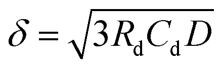 .51 EIS spectra for the CO2RR conditions in a flow cell were obtained and fitted with the circuit model shown in Fig. 3e. Fig. 3f reveals a prominent diffusion impedance in the low-frequency region, indicating that the electrode was highly sensitive to local CO2 concentration, and CO2 diffusion was a key factor influencing CO2RR performance, especially for molecular catalysts. The fitting results, as shown in Table S2,† revealed that the diffusion layer thicknesses for CoPc/CNT, PTFE-CoPc/CNT, and AD-PTFE-CoPc/CNT were 3.76 μm, 3.12 μm, and 1.05 μm, respectively. A reduced diffusion layer thickness improved CO2 mass transfer, resulting in a higher local CO2 concentration at the catalyst surface, which promoted CO2 coordination adsorption and enhanced reaction selectivity, manifested as a higher FECO. In addition, since the electrochemical surface area (ECSA) is proportional to the double-layer capacitance (Cdl), the Cdl obtained from EIS can reflect ECSA.52 ECSA refers to the portion of an electrode's surface that is in contact with and accessible to the electrolyte.38,53 The Cdl decreased from 1.88 mF in the CoPc/CNT electrode to 1.20 mF in the PTFE-CoPc/CNT electrode and further dropped to 0.86 mF in the AD-PTFE-CoPc/CNT (Table S2†). This demonstrated that PTFE particles can enhance the hydrophobicity of the electrode, with amorphism-dominated PTFE further amplifying this effect. Thus, variations in ECSA indicated differing degrees of three-phase interface contact, which in turn influenced catalytic activity. Although AD-PTFE-CoPc/CNT has a relatively small ECSA compared with the other samples, it still exhibited the best performance, confirming the effectiveness of tuning the microenvironment. Furthermore, CoPc/CNT had the lowest Rct (4.25 Ω cm2) due to PTFE introduction restricting electron transfer, while AD-PTFE-CoPc/CNT exhibited lower Rct (6.96 Ω cm2) compared to PTFE-CoPc/CNT (12.1 Ω cm2) due to the larger local CO2 concentration reducing electrochemical reaction resistance. This effect facilitated the CO2RR and the corresponding electron transfer, resulting in higher catalytic activity, higher current density, and higher TOF.
Characterization of hydrophobic interfaces
Confocal laser scanning microscopy (CLSM) was employed to observe the microenvironment at the interface, further corroborating the relationship between electrode hydrophobicity and local CO2 concentration.54 To determine the microscale contact state of the three electrodes, cross-section images along the z-axis were compared. Fig. 4a–c display the cross-section structures of CoPc/CNT, PTFE-CoPc/CNT, and AD-PTFE-CoPc/CNT, respectively. As shown in Fig. 4b and c, there were numerous non-luminescent spots at the contact interface of PTFE-CoPc/CNT and AD-PTFE-CoPc/CNT, which were occupied by the gas phase and increased the degree of liquid–gas interface contact. This was further confirmed by analyzing the fluorescence intensity decay along the z-axis (Fig. 4d). Due to the strong light absorption and blocking effect of the solid phase, the typical decay distance at the liquid–solid interface is significantly shorter than that at the liquid–gas interface. The decay distance of CoPc/CNT was 2.5 μm, which was typical of a liquid–solid interface. For PTFE-CoPc/CNT and AD-PTFE-CoPc/CNT, the decay distances increased to 3.9 and 7.9 μm, respectively, indicating that the liquid–gas interface gradually replaced the liquid–solid interface. AD-PTFE-CoPc/CNT exhibited the highest level of hydrophobicity, consequently displaying the most significant liquid–gas interface. Additionally, cross-section SEM revealed that the catalyst layer thickness for all three electrodes was approximately the same (Fig. S15†). Hence, the variation in catalyst layer hydrophobicity and local CO2 concentration was not induced by changes in thickness. Thus, it could be concluded that the presence of PTFE facilitated CO2 mass transport, maintaining a high CO2 concentration near the CoPc sites, thereby enhancing both the selectivity and activity of the CO2RR (Fig. 4e). | ||
| Fig. 4 (a–c) Cross-section fluorescence images of electrodes coated with CoPc/CNT, PTFE-CoPc/CNT and AD-PTFE-CoPc/CNT. (d) Corresponding z axis fluorescence intensity line scans of (a–c). (e) Schematic illustration of the impact of PTFE on the local CO2 and CoPc microenvironment. | ||
Performance at industrial current in a membrane electrode assembly (MEA)
A membrane electrode assembly (MEA) with an effective area of 4 cm2 was employed to test the industrial operation of catalysts. AD-PTFE-CoPc/CNT exhibited a consistent selectivity of over 90% within the current range of 0–100 mA cm−2 (Fig. 5a and S16†). In contrast, PTFE-CoPc/CNT and CoPc/CNT exhibited a decreased FECO to 75% and 57%, respectively, at 100 mA cm−2 (Fig. S17 and S18†). AD-PTFE-CoPc/CNT maintained a FECO of over 85% at current density expanded to 200 mA cm−2 (Fig. 5b), which was possibly due to the absence of the cathodic electrolyte in the MEA system, leading to an increased local CO2 concentration. As shown in Fig. S19,† AD-PTFE-CoPc/CNT exhibited stable operation for 3 hours without electrode flushing, maintaining a FECO of over 85%. The gradual increase in operating voltage was likely due to the salt precipitation during the reaction, which increases the overall resistance of the reactor. The stability of the catalyst layer improved with the addition of either PTFE or amorphism-dominated PTFE. This indicates that, under high current conditions, creating a microscale hydrophobic environment not only maintained a high FECO but also enhanced the electrode's long-term stability. To investigate the chemical and structural stability of the electrocatalysts, the electrode loaded with AD-PTFE-CoPc/CNT was characterized in the pristine state and after the reaction. The results of EDS and SEM indicated that the morphology of AD-PTFE-CNT remained unchanged (Fig. S20, S21a and b†). The XRD results further confirmed that the crystallinity of PTFE is stable (Fig. S21c†). XPS was further employed to monitor the change of the chemical state of CoPc (Fig. S21d†). The positions of the characteristic peaks of Co 2p remain consistent after the reaction compared to those of the pristine CoPc sample, suggesting that the chemical state of Co is stable during the electrochemical reaction. The AC-TEM image of AD-PTFE-CoPc/CNT after the reaction showed that Co sites still appeared to be approximate single atoms with good dispersion, indicating the structural stability of the sample (Fig. S22†). To investigate the effect of the reaction on the hydrophobic environment of the catalyst layer, CLSM characterization of the GDE coated with AD-PTFE-CoPc/CNT after the reaction was conducted. The result showed that the fluorescence decay distance along the z-axis after the reaction was 7.0 μm, which was almost unchanged compared to 7.9 μm in the pristine state (Fig. S23 and S24†). Additionally, the contact angle of the electrode after the reaction was measured, which was 145°, nearly unchanged from 142.1° in the pristine state (Fig. S25†). Therefore, the reaction had little impact on the hydrophobic environment of the catalyst layer. Additionally, AD-PTFE-CoPc/CNT exhibited superior JCO (96.4 mA cm−2 at 100 mA cm−2), demonstrating noteworthy electrochemical activity (Fig. 5c), which could also be explained by TOF (41.3 s−1 at 100 mA cm−2, Fig. S26†). PTFE-CoPc/CNT and AD-PTFE-CoPc/CNT showed a narrower decrease in energy efficiency (EE) than CoPc/CNT with increasing current (Fig. 5d). AD-PTFE-CoPc/CNT still maintained an EE of over 40% at 100 mA cm−2, likely due to its lower reaction resistance and thicker diffusion layer, thus reducing reaction impedance and overpotential. | ||
| Fig. 5 (a) FECO for CoPc/CNT, PTFE-CoPc/CNT, and AD-PTFE-CoPc/CNT at a series of applied currents in a MEA. (b) FECO of AD-PTFE-CoPc/CNT in a wider range of series currents in the MEA. (c and d) JCO and EE of the CO2RR for CoPc/CNT, PTFE-CoPc/CNT, and AD-PTFE-CoPc/CNT. | ||
Conclusion
In summary, we proposed a strategy to enhance the performance of molecular catalysts for the CO2RR by controlling the hydrophobicity with PTFE through crystallinity modulation. By leveraging interface adhesion during melt crystallization, CNTs modified with amorphism-dominated PTFE were obtained. Compared to spherulitic PTFE, the decrease in crystallinity resulted in increased polymer free volume and hydrophobic surface area, effectively strengthening the hydrophobicity of the CoPc microenvironment. The obtained catalyst achieved a maximum FECO of 96% in the MEA and maintained a consistent FE exceeding 85% at a total current of 0.8 A. Diffusion impedance testing and interface characterization jointly demonstrated the expansion of local CO2 concentration, facilitating CO2 adsorption coordination and thereby enhancing CO2RR performance. This approach is believed to be flexibly applied to other molecular catalysts and different polymer systems. For phthalocyanine- and porphyrin-based molecular catalysts, where CO2 adsorption and coordination were key steps for controlling reaction rate and selectivity, hydrophobic polymer modification effectively created a hydrophobic microenvironment that enhanced the local CO2 concentration. Additionally, by applying annealing treatments above the melting point of crystalline polymers, amorphism-dominated polymers with an expanded hydrophobic surface area were obtained. This study provided new insights into the regulation of PTFE hydrophobic modification and a general approach for enhancing the CO2RR performance of molecular catalysts through interface engineering.Data availability
The data supporting this article have been included as part of the ESI.†Author contributions
J. G. and P. Z. supervised the research. Z. Q., P. Z. and J. G. conceived the ideas and designed the experiments. Z. Q., H. Z., D. S., G. Z., H. G. and M. J. performed the experiments, device fabrication, electrochemical measurements, materials characterization and data analysis. Z. Q., P. Z., and J. G. wrote the manuscript. All authors discussed the experiments and commented on the manuscript.Conflicts of interest
There are no conflicts to declare.Acknowledgements
This work was supported by the National Key R&D Program of China (2021YFA1501503), the National Natural Science Foundation of China (22121004, 22038009, and 22250008), the Haihe Laboratory of Sustainable Chemical Transformations (24HHWCSS00013), the Natural Science Foundation of Tianjin City (21JCZXJC00060), the Program of Introducing Talents of Discipline to Universities (BP0618007) and the Xplorer Prize.References
- D. D. Zhu, J. L. Liu and S. Z. Qiao, Adv. Mater., 2016, 28, 3423–3452 CrossRef CAS PubMed.
- X. Du, P. Zhang, G. Zhang, H. Gao, L. Zhang, M. Zhang, T. Wang and J. Gong, Natl. Sci. Rev., 2024, 11, nwad149 Search PubMed.
- G. Jiang, D. Han, Z. Han, J. Gao, X. Wang, Z. Weng and Q.-H. Yang, Trans. Tianjin Univ., 2022, 28, 265–291 CrossRef CAS.
- D.-H. Nam, P. De Luna, A. Rosas-Hernández, A. Thevenon, F. Li, T. Agapie, J. C. Peters, O. Shekhah, M. Eddaoudi and E. H. Sargent, Nat. Mater., 2020, 19, 266–276 CrossRef CAS PubMed.
- O. S. Bushuyev, P. De Luna, C. T. Dinh, L. Tao, G. Saur, J. van de Lagemaat, S. O. Kelley and E. H. Sargent, Joule, 2018, 2, 825–832 CrossRef CAS.
- P. De Luna, C. Hahn, D. Higgins, S. A. Jaffer, T. F. Jaramillo and E. H. Sargent, Science, 2019, 364, eaav3506 Search PubMed.
- H. Yao, M.-Y. Wang, C. Yue, B. Feng, W. Ji, C. Qian, S. Wang, S. Zhang and X. Ma, Trans. Tianjin Univ., 2023, 29, 254–274 CrossRef CAS.
- Z. Gao, J. Li, Z. Zhang and W. Hu, Chin. Chem. Lett., 2022, 33, 2270–2280 CrossRef CAS.
- S. Ren, D. Joulié, D. Salvatore, K. Torbensen, M. Wang, M. Robert and C. P. Berlinguette, Science, 2019, 365, 367–369 CrossRef CAS PubMed.
- F. Li, A. Thevenon, A. Rosas-Hernández, Z. Wang, Y. Li, C. M. Gabardo, A. Ozden, C. T. Dinh, J. Li, Y. Wang, J. P. Edwards, Y. Xu, C. McCallum, L. Tao, Z.-Q. Liang, M. Luo, X. Wang, H. Li, C. P. O'Brien, C.-S. Tan, D.-H. Nam, R. Quintero-Bermudez, T.-T. Zhuang, Y. C. Li, Z. Han, R. D. Britt, D. Sinton, T. Agapie, J. C. Peters and E. H. Sargent, Nature, 2020, 577, 509–513 Search PubMed.
- E. Boutin, M. Wang, J. C. Lin, M. Mesnage, D. Mendoza, B. Lassalle-Kaiser, C. Hahn, T. F. Jaramillo and M. Robert, Angew. Chem., Int. Ed., 2019, 58, 16172 CrossRef CAS PubMed.
- Z. Jiang, Z. Zhang, H. Li, Y. Tang, Y. Yuan, J. Zao, H. Zheng and Y. Liang, Adv. Energy Mater., 2023, 13, 2203603 CrossRef CAS.
- X. Kong, Y. Liu, P. Li, J. Ke, Z. Liu, F. Ahmad, W. Yan, Z. Li, Z. Geng and J. Zeng, Appl. Catal., B, 2020, 268, 118452 CrossRef CAS.
- Y. Wu, Y. Liang and H. Wang, Acc. Chem. Res., 2021, 54, 3149–3159 CrossRef CAS PubMed.
- R. Francke, B. Schille and M. Roemelt, Chem. Rev., 2018, 118, 4631–4701 CrossRef CAS PubMed.
- L. Sun, V. Reddu, A. C. Fisher and X. Wang, Energy Environ. Sci., 2020, 13, 374–403 RSC.
- Y. Wu, G. Hu, C. L. Rooney, G. W. Brudvig and H. Wang, ChemSusChem, 2020, 13, 6296–6299 CrossRef CAS PubMed.
- X. Zhang, Y. Wang, M. Gu, M. Wang, Z. Zhang, W. Pan, Z. Jiang, H. Zheng, M. Lucero, H. Wang, G. E. Sterbinsky, Q. Ma, Y.-G. Wang, Z. Feng, J. Li, H. Dai and Y. Liang, Nat. Energy, 2020, 5, 684–692 CrossRef CAS.
- A. J. Sathrum and C. P. Kubiak, J. Phys. Chem. Lett., 2011, 2, 2372–2379 CrossRef CAS.
- T. Burdyny and W. A. Smith, Energy Environ. Sci., 2019, 12, 1442–1453 RSC.
- M. Zhu, R. Ye, K. Jin, N. Lazouski and K. Manthiram, ACS Energy Lett., 2018, 3, 1381–1386 CrossRef CAS.
- A. N. Marianov and Y. Jiang, Acc. Mater. Res., 2022, 3, 620–633 CrossRef CAS.
- L. Sun, V. Reddu, S. Xi, C. Dai, Y. Sheng, T. Su, A. C. Fisher and X. Wang, Adv. Energy Mater., 2022, 12, 2202108 CrossRef CAS.
- X. Zhang, Z. Wu, X. Zhang, L. Li, Y. Li, H. Xu, X. Li, X. Yu, Z. Zhang, Y. Liang and H. Wang, Nat. Commun., 2017, 8, 14675 CrossRef PubMed.
- J. Zhang, H. Chen, S. Liu, L.-D. Wang, X.-F. Zhang, J.-X. Wu, L.-H. Yu, X.-H. Zhang, S. Zhong, Z.-Y. Du, C.-T. He and X.-M. Chen, J. Am. Chem. Soc., 2023, 145, 20000–20008 CrossRef CAS PubMed.
- F. Tang, Z. Wang, S. Wang, S. Xing, C. Li, S. Wang, Z. Jin and J.-B. Baek, Chem. Eng. J., 2024, 487, 150433 CrossRef CAS.
- J. Ding, Z. Wei, F. Li, J. Zhang, Q. Zhang, J. Zhou, W. Wang, Y. Liu, Z. Zhang, X. Su, R. Yang, W. Liu, C. Su, H. B. Yang, Y. Huang, Y. Zhai and B. Liu, Nat. Commun., 2023, 14, 6550 CrossRef CAS PubMed.
- S. Sato, K. Sekizawa, S. Shirai, N. Sakamoto and T. Morikawa, Sci. Adv., 2023, 9, eadh9986 CrossRef CAS PubMed.
- Y. Jeong, Y. Kim, Y. J. Kim and J. Y. Park, Adv. Sci., 2024, 11, 2304735 Search PubMed.
- K. H. Do, D. Praveen Kumar, A. Putta Rangappa, J. Wang, Y. Hong, E. Kim, D. Amaranatha Reddy and T. Kyu Kim, Mater. Today Chem., 2021, 22, 100589 Search PubMed.
- T. Chan, C. J. Kong, A. J. King, F. Babbe, R. R. Prabhakar, C. P. Kubiak and J. W. Ager, ACS Appl. Energy Mater., 2024, 7, 3091–3098 CrossRef CAS PubMed.
- P. Yue, Q. Fu, J. Li, L. Zhang, L. Xing, Z. Kang, Q. Liao and X. Zhu, Chem. Eng. J., 2021, 405, 126975 Search PubMed.
- J. A. Rabinowitz, D. S. Ripatti, R. G. Mariano and M. W. Kanan, ACS Energy Lett., 2022, 7, 4098–4105 CrossRef CAS.
- K. E. Rivera Cruz, Y. Liu, T. L. Soucy, P. M. Zimmerman and C. C. L. McCrory, ACS Catal., 2021, 11, 13203–13216 CrossRef CAS.
- T. L. Soucy, W. S. Dean, J. Zhou, K. E. Rivera Cruz and C. C. L. McCrory, Acc. Chem. Res., 2022, 55, 252–261 CrossRef CAS PubMed.
- C. M. Lieber and N. S. Lewis, J. Am. Chem. Soc., 1984, 106, 5033–5034 CrossRef CAS.
- J. Lin, S. Yan, C. Zhang, Q. Hu and Z. Cheng, ACS Appl. Mater. Interfaces, 2022, 14, 8623–8632 CrossRef CAS PubMed.
- Z. Xing, X. Hu and X. Feng, ACS Energy Lett., 2021, 6, 1694–1702 CrossRef CAS.
- L. Li, J. Chen, V. S. S. Mosali, Y. Liang, A. M. Bond, Q. Gu and J. Zhang, Angew. Chem., Int. Ed., 2022, 61, e202208534 CrossRef CAS PubMed.
- X.-M. Hu, M. H. Rønne, S. U. Pedersen, T. Skrydstrup and K. Daasbjerg, Angew. Chem., Int. Ed., 2017, 56, 6468–6472 CrossRef CAS PubMed.
- B. Feng, Y. Li, S. Wu, H. Wang, Z. Tao and X. Fang, Mater. Des., 2016, 108, 411–417 CrossRef CAS.
- M. Nofar, A. Tabatabaei, A. Ameli and C. B. Park, Polymer, 2013, 54, 6471–6478 CrossRef CAS.
- M. Nofar, A. Tabatabaei and C. B. Park, Polymer, 2013, 54, 2382–2391 CrossRef CAS.
- M. Nofar, W. Zhu and C. B. Park, Polymer, 2012, 53, 3341–3353 CrossRef CAS.
- T. Y. Guo, Q. H. Zeng, C. H. Zhao, Q. L. Liu, A. M. Zhu and I. Broadwell, J. Membr. Sci., 2011, 371, 268–275 CrossRef CAS.
- Q. Fan, P. Hou, C. Choi, T. Wu, S. Hong, F. Li, Y. Soo, P. Kang, Y. Jung and Z. Sun, Adv. Energy Mater., 2020, 10, 1903068 CrossRef CAS.
- G. Dlubek, A. Sen Gupta, J. Pionteck, R. Häßler, R. Krause-Rehberg, H. Kaspar and K. H. Lochhaas, Polymer, 2005, 46, 6075–6089 CrossRef CAS.
- U. O. Nwabara, A. D. Hernandez, D. A. Henckel, X. Chen, E. R. Cofell, M. P. de-Heer, S. Verma, A. A. Gewirth and P. J. A. Kenis, ACS Appl. Energy Mater., 2021, 4, 5175–5186 CrossRef CAS.
- A. Huang, F. Liu, Z. Cui, H. Wang, X. Song, L. Geng, H. Wang and X. Peng, Compos. Sci. Technol., 2021, 214, 108980 CrossRef CAS.
- W. Kwon, J.-M. Kim and S.-W. Rhee, Electrochim. Acta, 2012, 68, 110–113 CrossRef CAS.
- W. Zhang, J. Ma, P. Wang, Z. Wang, F. Shi and H. Liu, J. Membr. Sci., 2016, 502, 37–47 CrossRef CAS.
- S. S. Jeon, P. W. Kang, M. Klingenhof, H. Lee, F. Dionigi and P. Strasser, ACS Catal., 2023, 13, 1186–1196 CrossRef CAS.
- Z. Xing, L. Hu, D. S. Ripatti, X. Hu and X. Feng, Nat. Commun., 2021, 12, 136 CrossRef CAS PubMed.
- L. Xiong, X. Fu, Y. Zhou, P. Nian, Z. Wang and Q. Yue, ACS Catal., 2023, 6652–6660 CrossRef CAS.
Footnote |
| † Electronic supplementary information (ESI) available. See DOI: https://doi.org/10.1039/d4sc08219b |
| This journal is © The Royal Society of Chemistry 2025 |