DOI:
10.1039/D5RA00745C
(Paper)
RSC Adv., 2025,
15, 17230-17240
Synthesis of dendritic mesoporous silica nanoparticles by ultrasonic assisted microchannel continuous flow reaction†
Received
1st February 2025
, Accepted 18th May 2025
First published on 22nd May 2025
Abstract
Dendritic mesoporous silica nanoparticle (DMSN) possess advantages such as high specific surface area, excellent chemical stability, and good biocompatibility, which make it is a research hotspot in the field of nanomaterials. The microemulsion templating method (MET) is one of the common methods for synthesizing DMSN, but it typically requires a long reaction time. In this paper, we propose an ultrasonic-assisted microchannel continuous flow reaction to shorten the reaction time. The ultrasonic-assisted microchannel continuous flow reaction system consists of an injection system, dispersion chip, ultrasonic-assisted mixing chip, reaction coil, and condensation coil. By optimizing factors including total flow rate, material ratio, reaction temperature, reaction coil inner diameter, reaction coil length, and the concentration of NaOH and HCl in the microemulsion, the optimal synthesis conditions were determined. Under the best conditions, the reaction time for synthesizing DMSN was 33.6 min; compared to the 24 h required for synthesis in the three-neck flask, it had been shortened by 42 times. The findings of this study provide a new method for the preparation of DMSN.
1 Introduction
Dendritic mesoporous silica nanoparticles (DMSNs)1–5 possess numerous advantages over conventional spherical nanomaterials, including extensive pore channels, high surface area, and favorable biocompatibility.6–8 These characteristics give DMSNs various applications, such as in catalysis, gas capture, electronics, sensors, and biomedical fields.9–15 Currently, there are main three synthesis methods for DMSNs:16 microemulsion template (MET) method, organic silane-assisted co-condensation (OAC) method, and spherical micelle self-assembly approach (SMSAA). Among these, the MET method is widely employed due to its diverse microemulsion substructures and ease of control. However, the synthesis of DMSNs via the MET usually has a long reaction time because the heterogeneous reaction is slow. Polshettiwar et al.3 utilized microwave-assisted hydrothermal technology for DMSN synthesis and the reaction time was 4 h at 120 °C when employing a microemulsion comprising tetraethyl orthosilicate (TEOS), cyclohexane, pentanol, cetylpyridinium bromide (CPB), urea, and water. Lee et al.17,18 synthesized DMSNs using a microemulsion consisting of cetyltrimethylammonium bromide (CTAB), TEOS, n-butanol, cyclohexane, and urea, while the reaction duration was 20 h. Liu et al.19 developed a strategy with a low oil-to-water volume ratio (0.025–0.045) and synthesized DMSNs through a microemulsion comprising TEOS, CTAB, ammonia, ethanol, and n-pentanol, which took 6 h at 30 °C. From the perspective of improving reaction efficiency and reducing energy consumption, finding a more efficient synthesis method to prepare DMSNs has important research significance and application prospects.
Microchannel continuous flow reaction technology is an emerging technique with significant potential for nanoparticle manufacturing,20–22 which offers new opportunities in nanomaterials engineering and applications. Owing to its advantages of high efficiency, cost-effectiveness, and high precision, this technology has been widely utilized in various fields including the synthesis of biopolymers,23 biosensing,24 pharmaceuticals and tissue engineering.25 In contrast to traditional batch reactions, microchannel continuous flow reactions minimize the localized variation through reducing the reactor dimensions. Its high surface-to-volume ratio of microchannels enhances the mass and heat transfer, which is helpful for shortening the reaction time. Recent literature has documented the successful use of microchannel continuous flow reactors for the synthesis of silica with distinctive morphologies.26–28 For instance, Hao et al.29 designed a dual-inlet, single-outlet micro spiral channel to synthesize the two-dimensional, hollow, sandwich-like mesoporous silica nanosheets with a rippled surface. They also synthesized various silica materials, including functional mesoporous silica nanofibers30 and multifunctional sub-micrometric hollow silica spheres.31 Additionally, Chen et al.11 proposed a dual-flow confined jet impingement continuous microchannel reactor to prepare the ultra-high surface area mesoporous silica nanospheres with small diameters (∼200 nm). Lee et al.32 utilized a microfluidic device to fabricate micro-sized mesoporous silica microspheres with controllable size and surface morphology. These findings confirm the feasibility of employing microchannel reactors for the synthesis of nano-silica. Consequently, this study aims to utilize a microchannel continuous flow reactor for the synthesis of DMSN.
This paper presents a novel approach to synthesize DMSN by integrating a microchannel reactor with ultrasound-assisted method. This method is well-suited for laboratory research, easy access to materials and ease of assembly. The reaction system comprised an injection system, a dispersion chip, an ultrasound-enhanced mixing chip, a reaction coil, and a condenser coil. Within the dispersion chip, a dual-section flow strategy was employed to effectively disperse TEOS in the microemulsion. The mixing chip utilized ultrasound assistance to facilitate thorough interaction between TEOS and the microemulsion. A series of reaction conditions, including material flow rates, total flow rates, temperature, coil length, and coil inner diameter, were investigated for their influences on the morphological characteristics of mesoporous silica. By adjusting the pH, the synthesis process was optimized to achieve a stable and uniform DMSN product. In comparison to the conventional three-neck flask method for DMSN synthesis, this approach significantly reduced the reaction time required.
2 Experimental section
2.1 Materials
Urea, sodium hydroxide, tetraethyl orthosilicate (TEOS), cetyltrimethylammonium bromide (CTAB), n-butanol, cyclohexane, NaOH and HCl were purchased from Chengdu Kelong Chemical Reagent Co., Ltd.
2.2 Experimental method
2.2.1 Method for preparing DMSN via batch method. Preparation of DMSN through three-neck flask was conducted according to ref. 18. Firstly, the microemulsion was prepared and then TEOS was added into the microemulsion for reaction under vigorous stirring. For the microemulsion, the aqueous phase (W) was 0.4 mol L−1 urea aqueous solution, the surfactant phase (S) was a mixture of butanol and CTAB (mass ratio was 1![[thin space (1/6-em)]](https://www.rsc.org/images/entities/char_2009.gif) :1), while the oil phase (O) was cyclohexane. In the three-neck flask, 46.87 g urea aqueous solution (47 mL), 3.12 g CTAB, 3.12 g butanol (3.8 mL), and 46.87 g cyclohexane (60 mL) were added sequentially and vigorously stirred at room temperature to achieve the microemulsion. Subsequently, 5.85 g TEOS (6 mL) was added dropwise into the microemulsion at a controlled rate of 1–3 drops per second. Following the complete addition of TEOS, the mixture was stirred vigorously for an additional 30 min, after which the reaction temperature was raised to 70 °C and maintained for 24 h. Upon completion of the reaction, the reaction mixture was first subjected to rotary evaporation, followed by freeze-drying. Finally, the product was calcined at 600 °C for 8 h in a muffle furnace to obtain the desired material.
:1), while the oil phase (O) was cyclohexane. In the three-neck flask, 46.87 g urea aqueous solution (47 mL), 3.12 g CTAB, 3.12 g butanol (3.8 mL), and 46.87 g cyclohexane (60 mL) were added sequentially and vigorously stirred at room temperature to achieve the microemulsion. Subsequently, 5.85 g TEOS (6 mL) was added dropwise into the microemulsion at a controlled rate of 1–3 drops per second. Following the complete addition of TEOS, the mixture was stirred vigorously for an additional 30 min, after which the reaction temperature was raised to 70 °C and maintained for 24 h. Upon completion of the reaction, the reaction mixture was first subjected to rotary evaporation, followed by freeze-drying. Finally, the product was calcined at 600 °C for 8 h in a muffle furnace to obtain the desired material.
2.2.2 Method for preparing DMSN by microchannel continuous flow reaction. The schematic diagram for the continuous flow microchannel reaction used to synthesize DMSN is illustrated in Fig. 1. The reaction employed microemulsions as described in Section 2.2.1. The microemulsion (ME) and TEOS were injected into the dispersion chip using an injection pump (Model: XF-101PD, Suzhou Xunfei Scientific Instrument Co., Ltd). Subsequently, the mixture entered an ultrasonic-assisted mixing chip, followed by the reaction step in the high-temperature coil. After the reaction, the crude product was obtained through condensation in the low-temperature coil, and post-processing was conducted as described in Section 2.2.1. The design schematics of the dispersion and mixing chips are presented in Fig. 2 (with physical images shown in Fig. S1†). Both chips are constructed from quartz glass, sourced from Suzhou Wenhao Microfluidic Technology Co., Ltd. The reaction coils are fabricated from 316L stainless steel, procured from Mingyuan Chromatography Consumables Store (with physical images in Fig. S2†).
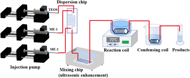 |
| | Fig. 1 Schematic diagram of the preparation of DMSN by microchannel continuous flow reaction. | |
 |
| | Fig. 2 The design of (a) dispersion chip and (b) mixing chip. | |
2.3 Characterization
The morphology of the reaction products was observed by scanning electron microscopy (SEM, ZEISS Gemini SEM 300, Germany) and transmission electron microscopy (TEM, FEI Tecnai G2 F20, USA). The structures of the products were determined using an infrared spectrometer (IR, Thermo Fisher Scientific Nicolet iS20, USA) and an X-ray photoelectron spectrometer (XPS, Thermo Scientific K-Alpha, USA), respectively.
3 Results and discussion
3.1 Study on the preparation conditions of DMSN via batch method
The reaction temperature and the feed ratio of the microemulsion to TEOS are the two critical parameters influencing the synthesis of DMSN. In this section, the effects of these two parameters on DMSN preparation were investigated, providing a reference for the microchannel continuous flow synthesis of DMSN. Additionally, the impact of reaction time on DMSN fabrication was explored, offering a foundational comparison with the microchannel continuous flow process for DMSN preparation.
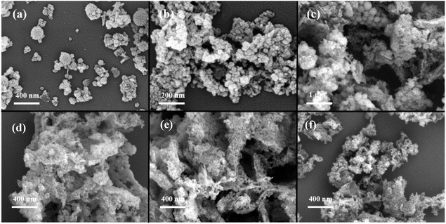
When the microemulsion was 93.75 g, TEOS was 5.85 g (resulting in a mass ratio of microemulsion to TEOS of 16:1), the stirring speed was 1200 rpm, and the reaction time was 24 h, the influence of reaction temperature on the resulting product was investigated, and the SEM images of the product are displayed in Fig. 3(a). The results indicated that at a reaction temperature of 55 °C, the product did not exhibit a defined morphology. In contrast, when the temperature was ≥60 °C, the product presented as dendritic particles. This phenomenon arises from the predominance of condensation reaction kinetics at elevated temperatures (>50 °C), coupled with the diminished synergistic promotion of silica-initiated bonding by thermodynamics and kinetics.33 As the temperature increases, the condensation rate of TEOS accelerates. Consequently, at 55 °C, the condensation rate of TEOS remains relatively slow, hindering the formation of more ordered structures. With a further increase in temperature (>60 °C), the condensation rate significantly escalates, facilitating the formation of more ordered structures. And the urea aqueous solution initiates hydrolysis at around 60 °C, resulting in a gradual increase in the pH of the solution, which subsequently accelerates the condensation rate. Notably, as the temperature increased, a trend towards smaller particle sizes was observed, accompanied by a more compact and intricate “wrinkling” structure that became progressively challenging to discern. At 75 °C, which is nearing the boiling point of the organic phase, the probability of successful formation of DMSN significantly decreased.
 |
| | Fig. 3 Synthesis of DMSN via batch method; the effects of (a) reaction temperature, (b) mass ratio of microemulsion to TEOS and (c) reaction time on the SEM morphology of resulting products; (a1) 55 °C, (a2) 65 °C, (a3) 70 °C, (a4) 75 °C; (b1) 20:1, (b2) 16:1, (b3) 10.7:1, (b4) 9:1; (c1) 2 h, (c2) 6 h, (c3) 12 h and (c4) 16 h. | |
When the microemulsion was 93.75 g, the stirring speed was 1200 rpm, and the reaction time was 24 h, the effect of the mass ratio of microemulsion to TEOS on the resulting product was investigated. As illustrated in Fig. 3(b), it was evident that when the mass ratio of microemulsion to TEOS was ≤16:1, this mass ratio had a negligible effect on the morphology of the resulting products. According to the reaction mechanism of MET, TEOS serves as the silicon source in the reaction, and its mass significantly impacts the product yield (see Table 1). When the TEOS mass exceeded a certain threshold, the product mass showed minimal change. An excessive amount of TEOS may not effectively participate in the reaction, while competitive reactions among reactants prevent any enhancement in product mass. Additionally, this excess TEOS can lead to the formation of irregular morphological structures adhering to the DMSN. The particle diameter of DMSN was observed to first decrease and subsequently increase with the rising mass of TEOS. At low concentrations of TEOS, the probability of OH- attacking TEOS increased, thereby accelerating hydrolysis and resulting in a greater number of smaller particles, which ultimately reduced the particle size of DMSN. Conversely, at high concentrations of the silicon source, the collision frequency among micelles increased, further accelerating hydrolysis, reducing interfacial strength, and enlarging the water droplet size, which ultimately led to an increase in the particle size of DMSN.34
Table 1 The influence of mass ratio of microemulsion to TEOS on product mass
| TEOS (mol) |
0.0225 |
0.0281 |
0.0421 |
0.0505 |
0.0562 |
| The mass ratio of microemulsion to TEOS |
20:1 |
16:1 |
10.7:1 |
9:1 |
8:1 |
| Product mass (g) |
0.108 |
0.109 |
0.288 |
0.457 |
0.46 |
When the microemulsion was 93.75 g, TEOS was 5.85 g (with a mass ratio of microemulsion to TEOS of 16:1), the stirring speed was 1200 rpm, and the reaction temperature was 70 °C, the influence of reaction time on the resulting product was investigated, and the SEM images of the product are displayed in Fig. 3(c). The results showed that an insufficient reaction time of 2 h did not yield the desired dendritic structure. However, an increased reaction time led to a gradual emergence of distinct wrinkled structures after 6 h, although these structures were not fully developed. When the reaction time was extended to 12 h, the ideal DMSN began to appear, and the morphology of the products obtained after 24 h exhibited commendable uniformity, with a particle size of approximately 120 nm.
3.2 Study on the conditions for preparation of DMSN by continuous flow reaction in microchannels
3.2.1 Effect of total flow rate and material ratio. When the length and inner diameter of the reaction coil were 10 m and 1 mm, respectively, and the reaction temperature was 70 °C, the effects of the total flow rate and material ratio on the reaction results were investigated. The detailed reaction conditions are listed in Table 2, and the SEM images of the products are presented in Fig. 4(a)–(f) (with TEM images shown in Fig. S3†). The results showed that as the total flow rate increased, the particle size of the products initially decreased and then exhibited irregular morphologies. At low flow rates, the long residence time of reactants in the mixing chip resulted in high mixing efficiency, which favored the growth of nanoparticles and facilitated a well-ordered arrangement of the microemulsions surrounding them. However, when the total flow rate reached or exceeded 560 μL min−1, numerous irregularly shaped products began to appear around the properly formed particles. Therefore, it is recommended that the total flow rate be set at 280 μL min−1. Additionally, the results indicated that when the flow rate of TEOS was low (30 μL min−1), it failed to enter the dispersion chip because the entry of ME-1 and ME-2 at both ends of the chip exerted pressure on the entry of TEOS. When the TEOS flow rate was increased to 40 μL min−1, the resulting product exhibited the morphology of nanoparticles. As the TEOS flow rate continued to increase, the products displayed irregular shapes. This irregularity may be attributed to insufficient shear force applied by the ME-1 reaction fluid to the TEOS at the T-junction channel. Consequently, excessive localized influx of TEOS occurred, leading to an increased concentration of negatively charged silicate monomers and oligomers resulting from TEOS hydrolysis. These hydrolyzed species competed for assembly with CTAB, resulting in the formation of numerous irregular products that adhered to the pre-formed surfaces. Based on these experimental findings, the recommended flow ratio of ME-1:TEOS:ME-2 was 160 μL min−1:40 μL min−1:80 μL min−1.
Table 2 Reaction conditions and reaction results when the total material flow rate and material ratio are changed
| No. |
ME-1 flow rate (μL min−1) |
TEOS flow rate (μL min−1) |
ME-2 flow rate (μL min−1) |
Residence time (min) |
Reaction result |
| a |
80 |
20 |
40 |
224 |
Irregular product attached to spherical particles |
| b |
160 |
40 |
80 |
112 |
Uniform morphology |
| c |
320 |
80 |
160 |
56 |
Irregular product attached to spherical particles |
| d |
160 |
30 |
80 |
116 |
TEOS cannot be injected in chip |
| e |
160 |
50 |
80 |
108 |
Irregular morphology |
| f |
160 |
60 |
80 |
104 |
Irregular morphology |
| g |
160 |
70 |
80 |
101 |
Irregular morphology |
| h |
160 |
80 |
80 |
98 |
Irregular morphology |
 |
| | Fig. 4 Synthesis of DMSN by continuous flow reaction in microchannels. The SEM images of reaction products obtained at different total flow rates and material ratios (a) 80 μL min−1:20 μL min−1:40 μL min−1, (b) 160 μL min−1:40 μL min−1:80 μL min−1, (c) 320 μL min−1:80 μL min−1:160 μL min−1, (d) 160 μL min−1:50 μL min−1:80 μL min−1, (e) 160 μL min−1:60 μL min−1:80 μL min−1, (f) 160 μL min−1:70 μL min−1:80 μL min−1. | |
3.2.2 Effect of reaction temperature. When the length and inner diameter of the reaction coil were 10 m and 1 mm, respectively, and the flow ratio of ME-1:TEOS:ME-2 was 160 μL min−1:40 μL min−1:80 μL min−1, the effect of reaction temperature on the results was investigated. The SEM images of the products are shown in Fig. 5. At the temperature of 55 °C, the product consisted of relatively smooth agglomerates of smaller particles. As the reaction temperature increased to 60 °C and 65 °C, the particles gradually became fuller, however, no distinct mesoporous structures were observed. At 70 °C, the particles exhibited a fuller appearance, with distinct mesoporous structures emerging. However, when the temperature reached 75 °C, the product lost its desired morphology due to the temperature approaching the boiling point of the organic phase. During this experiment, an ejection phenomenon was observed at the exit of the coil.
 |
| | Fig. 5 Synthesis of DMSN by continuous flow reaction in microchannels. The SEM images of the products obtained at different reaction temperatures (a) 55 °C, (b) 60 °C, (c) 65 °C, (d) 75 °C. | |
3.2.4 Effect of reaction coil length. When the inner diameter of the reaction coil was 1 mm, the flow ratio of ME-1:TEOS:ME-2 was 160 μL min−1:40 μL min−1:80 μL min−1, the reaction temperature was 70 °C, the influence of the reaction coil length on the reaction results was investigated, and the SEM images of the products are shown in Fig. 7 (with TEM images shown in Fig. S5†). When the reaction coil length was 1 m, the residence time was 11.2 min. The SEM image of the product (see Fig. 7(a)) revealed that it did not exhibit a spherical structure, which was attributed to the short reaction time and incomplete reaction at this stage. When the reaction coil length was increased to 3 m, the residence time extended to 33.6 min. The resulting product displayed a distinct spherical morphology with an approximate particle size of 120.5 ± 16.1 nm (see Fig. 7(b)), similar to that obtained from the three-neck flask. This result indicated that a longer residence time had a stabilizing effect on the condensation of hydrolyzed TEOS.31 Furthermore, the findings suggested that our microchannel reactor can serve as an efficient platform for the production of DMSN, offering faster and more effective capabilities than conventional batch reactors. When the reaction coil length was increased to 10 m, the residence time reached 112 min. The SEM image of the product (see Fig. 5(d)) illustrated an aggregated morphology consisting of smaller particles. The distinct dendritic structure was not observed, possibly because the particles were too small.
 |
| | Fig. 7 Synthesis of DMSN by continuous flow reaction in microchannels. The SEM images of products obtained at different reaction coil lengths (a) 1 m, (b) 3 m. | |
3.2.5 Effect of pH. According to the above results, we found that the product lacked distinct folds, which may be attributed to the enhanced heat transfer provided by the microchannel, which facilitated the rapid decomposition of urea as a basic catalyst. This swift decomposition results in a rapid pH variation within the emulsion, accelerating the synthesis reaction and consequently leading to the absence of distinct folds in the product. It is important to note that the fold structure is closely related to the pH changes induced by the catalyst.18 Therefore, based on the experimental conditions, we fixed the coil length at 3 m with an inner diameter of 1 mm to investigate the reaction products upon the addition of varying concentrations of NaOH and HCl to the microemulsion. The SEM images of the reaction products are presented in Fig. 8 (with TEM images shown in Fig. S6†). The results of the SEM images for various concentrations of NaOH are shown in Fig. 8(a). The results indicated that the addition of 0.5 mmol of NaOH had a certain impact on the pH of the reaction system, although the pH ultimately converged to the equilibrium pH value of the urea solution over time. Based on the observations from the SEM images, it was evident that DMSNs were formed under the influence of 0.5 mmol of NaOH. However, the low concentration of NaOH accelerated the nucleation rate to some extent, resulting in the deposition of numerous irregularly shaped byproducts on the surface of the formed DMSNs. As the concentration of NaOH increased, its influence on the interfacial reactions intensified, particularly at the concentration of 3 mmol NaOH, where a notable number of folded structures were observed, although they were not well-defined. During this process, NaOH served as the primary catalyst, substituting for urea and effectively controlling the reaction rate. Interestingly, when the concentration of NaOH reached 4 mmol, a hollow silica nanosphere structure appeared. The experimental results when HCl was added are depicted in the SEM images in Fig. 8(b). It was clearly observable that when the HCl concentration was 0.5 mmol, the DMSNs exhibited excellent sphericity and a uniform particle size distribution. This result suggests that an appropriate concentration of HCl helped mitigate the pH fluctuations caused by the decomposition of urea, thereby improving the synthesis results. This finding differed somewhat from the observations during the synthesis of DMSNs using the three-neck flask method, particularly regarding pore size. Nevertheless, the products demonstrated uniformity in terms of sphericity, dispersibility, and particle size, indicating that the results were accurate and reliable. As the concentration of HCl increased and exceeded the neutralization capacity of urea, the products began to aggregate, and the mesoporous structures became unobservable.
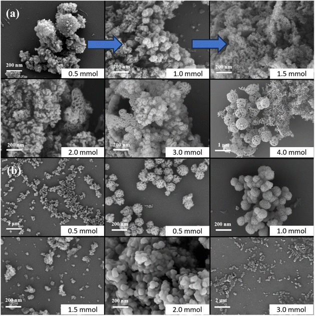 |
| | Fig. 8 Synthesis of DMSN by continuous flow reaction in microchannels. The SEM images of products prepared under different catalytic systems (a) 0.4 mol urea + different NaOH concentrations, (b) 0.4 mol urea + different HCl concentrations. | |
Based on the experimental results, the optimal conditions were determined as follows: flow ratio of ME-1:TEOS:ME-2 of 160 μL min−1:40 μL min−1:80 μL min−1 (with an HCl concentration in ME of 0.5 mmol), reaction temperature of 70 °C, reaction coil length of 3 m, and inner diameter of the reaction coil of 1 mm.
3.3 Formation of DMSN
From a microscopic perspective, the formation process of DMSN can be described as follows. TEOS was gradually added to the microemulsion and diffused from the oil phase to the oil–water interface. In the presence of the alkaline catalyst urea, TEOS underwent hydrolysis and condensation reactions, resulting in the formation of negatively charged silicate monomers and oligomers. Due to the hydrophilicity of the Si–OH groups, these compounds tended to arrange themselves in the hydrophilic regions at the oil–water interface. When the concentration of silicate monomers and oligomers reached the critical nucleation threshold, they interacted with the positively charged ends of CTAB molecules on the surface of the micelles in the aqueous phase. This interaction led to the assembly of composite micelles composed of SiO2/CTAB. Subsequently, these composite micelles aggregated while silica continued to grow, ultimately leading to the formation of spherical silica particles. Lee et al.17 provided a more detailed explanation of this process. The following equation represents the hydrolysis and condensation reactions of TEOS.| | |
Si(OCH2CH3)4 + H2O → Si(OH)4 + C2H5OH
| (1) |
| |
 | (2) |
3.4 Structure and characterization
The DMSN obtained under optimal conditions was characterized using transmission electron microscopy (TEM), and the results are presented in Fig. 9. The DMSN exhibited a dendritic structure radiating outward from the center. Additionally, the infrared (IR) spectrum and X-ray photoelectron spectroscopy (XPS) characterization results of the DMSN are shown in Fig. 10. In Fig. 10(a), the broad absorption peak at 810 cm−1 is attributed to the symmetric stretching vibrations of Si–O bonds. The absorption peak at 966 cm−1 corresponds to the vibrations of Si–OH groups, while the vibrational absorption peak associated with Si–O–Si bonds is evident at 1094 cm−1. Notably, the absorption peak at 3434 cm−1 is a typical characteristic peak for hydroxyl groups, confirming the presence of Si–OH and adsorbed water molecules on the sample's surface. As illustrated in Fig. 10(b), the surface of the sample predominantly consists of oxygen (O) and silicon (Si) elements. Elemental composition analysis revealed that the mass percentages of O and Si were 60.28 wt% and 30.18 wt%, respectively. It was noteworthy that the molar ratio of O to Si was 1:2, which was consistent with the chemical properties of SiO2. The XPS spectrum of the Si element (see Fig. 10(c)) exhibited a binding energy of 103.87 eV, corresponding to the literature value35 (103.3 eV) for the Si–O bond. Meanwhile, the XPS spectrum of the O element (see Fig. 10(d)) revealed a binding energy of 533.07 eV, which aligned with reported literature values (532.7–533.2 eV) for the O–Si bond.35 These results further confirmed that the synthesized sample was SiO2. The particle size distribution curve of DMSN is presented in Fig. 11. As illustrated in the figure, the particle size distribution of DMSN is relatively narrow, exhibiting a monomodal distribution. The average particle size is approximately 125.2 ± 12.7 nm.
 |
| | Fig. 9 TEM image of DMSN prepared under the optimal conditions. | |
 |
| | Fig. 10 (a) IR spectrum of DMSN; (b) XPS full spectrum scan of DMSN; (c) XPS fine spectrum of Si element; (d) XPS fine spectrum of O element. | |
 |
| | Fig. 11 Particle size distribution curve of DMSN. | |
4 Conclusion
In this work, DMSN was successfully synthesized by using ultrasound-assisted microchannel continuous-flow reaction. The ultrasound-assisted microchannel continuous-flow system consisted of injection system, dispersion chip (with two microemulsions and one TEOS inlet), ultrasound-assisted mixing chip, reaction coil, and condensation coil. The recommended conditions for the synthesis of DMSN via ultrasound-assisted microchannel continuous-flow reaction were as follows: flow ratio of ME-1:TEOS:ME-2 of 160 μL min−1:40 μL min−1:80 μL min−1 (the HCl concentration in ME was 0.5 mmol), reaction temperature of 70 °C, reaction coil length of 3 m, inner diameter of reaction coil of 1 mm. Under the recommended conditions, the reaction time for DMSN was 33.6 min, which was shortened by 42 times compared that prepared by the three-neck flask.
Data availability
All relevant data are within the paper. All data supporting the findings of this study are available within the paper and its ESI.†
Conflicts of interest
There are no conflicts to declare.
Acknowledgements
This work was supported by the National Natural Science Foundation of China (U22B6005). AI was used to help correct the grammar in the manuscript.
References
- C. T. Kresge, M. E. Leonowicz, W. J. Roth and J. C. Vartuli, Ordered mesoporous molecular sieves synthesized by a liquid-crystal template mechanism, Nature, 1992, 359, 710–712 CrossRef CAS.
- D. Y. Zhao, J. L. Feng, Q. S. Huo, N. Melosh, G. H. Fredrickson, B. F. Chmelka and G. D. Stucky, Triblock copolymer syntheses of mesoporous silica with periodic 50 to 300 angstrom pores, Science, 1998, 279, 548–552 CrossRef CAS.
- V. Polshettiwar, D. Cha, X. X. Zhang and J. M. Basset, High-surface-area silica nanospheres (KCC-1) with a fibrous morphology, Angew. Chem., Int. Ed., 2011, 49, 9652–9656 CrossRef.
- Y. B. Wang, X. Du, Z. Liu, S. H. Shi and H. M. Lv, Dendritic fibrous nano-particles (DFNPs) rising stars of mesoporous materials, J. Mater. Chem. A, 2019, 7, 5111–5152 RSC.
- K. Zhang, L. L. Xu, J. G. Jiang, N. Calin, K. F. Lam, S. J. Zhang, H. H. Wu, G. D. Wu, B. Albela, L. Bonneviot and P. Wu, Facile large-scale synthesis of monodisperse mesoporous silica nanospheres with tunable pore structure, J. Am. Chem. Soc., 2013, 135, 2427–2430 CrossRef CAS.
- X. Chun, L. Chang, Y. Wang and C. Z. Yu, Dendritic mesoporous nanoparticles structure, synthesis and properties, Angew. Chem., Int. Ed., 2022, 61, 1–22 Search PubMed.
- V. Polshettiwar, Dendritic fibrous nanosilica discovery, synthesis, formation mechanism, catalysis, and CO2 capture-conversion, Acc. Chem. Res., 2022, 55(10), 1395–1410 CrossRef CAS PubMed.
- Y. B. Wang, B. L. Zhang, X. P. Ding and X. Du, Dendritic mesoporous organosilica nanoparticles (DMONs) chemical composition, structural architecture, and promising applications, Nano Today, 2021, 39, 101231 CrossRef CAS.
- A. Maity, R. Belgamwar and V. Polshettiwar, Facile synthesis to tune size, textural properties and fiber density of dendritic fibrous nanosilica for applications in catalysis and CO2 capture, Nat. Protoc., 2019, 14, 2177–2204 CrossRef CAS PubMed.
- Y. Shu, J. H. Tao, Y. N. Wang, L. Z. Huang and Y. B. Wang, Facile synthesis and fine morphological tuning of dendritic mesoporous silica & titania nanospheres, J. Porous Mater., 2024, 31, 1375–1386 CrossRef CAS.
- Q. Chen, K. Chen, F. Yu, A. X. Guo, S. Q. Zou, M. Zhou, J. W. Li, J. M. Dan, Y. S. Li, B. Dai and X. H. Guo, Confined jet impingement continuous microchannel reactor synthesis of ultrahigh-quality mesoporous silica nanospheres for CO2 capture, Ind. Eng. Chem. Res., 2022, 61, 9300–9310 CrossRef CAS.
- S. L. Zhang, J. Bai, W. X. Kong, H. L. Song, Y. T. Liu, G. H. Liu, L. Ma, L. Y. Zhou and Y. J. Jiang, Dendritic mesoporous silica nanoparticles for enzyme immobilization, Green Chem. Eng., 2024, 5, 173–186 CrossRef.
- A. Maity and V. Polshettiwar, Dendritic fibrous nanosilica for catalysis, energy harvesting, carbon dioxide mitigation, drug delivery, and sensing, Chemsuschem, 2017, 10, 3866–3913 CrossRef CAS PubMed.
- M. Shaban and M. Hasanzadeh, Biomedical applications of dendritic fibrous nanosilica (DFNS) recent progress and challenges, RSC Adv., 2020, 10, 37116–37133 RSC.
- X. Du and S. Z. Qiao, Dendritic silica particles with center-radial pore Channels: promising platforms for catalysis and biomedical applications, Small, 2015, 11, 392–413 CrossRef CAS PubMed.
- P. Hao, B. Peng and B. Q. Shan, Comprehensive understanding of the synthesis and formation mechanism of dendritic mesoporous silica nanospheres, Nanoscale Adv., 2020, 2, 1792–1810 RSC.
- D. S. Moon and J. K. Lee, Tunable synthesis of hierarchical mesoporous silica nanoparticles with radial wrinkle structure, Langmuir, 2012, 28, 12341–12347 CrossRef CAS PubMed.
- D. S. Moon and J. K. Lee, Formation of wrinkled silica mesostructures based on the phase behavior of pseudoternary systems, Langmuir, 2014, 30, 15574–15580 CrossRef CAS PubMed.
- X. X. Liu, X. Zhang, J. Chen, C. H. Zhang, S. K. Feng and W. G. Zhang, Tunable synthesis of dendritic fibrous nano silica using 1-pentanol-water microemulsion at low oil to water ratio, Nanotechnology, 2022, 33, 325601 CrossRef CAS PubMed.
- K. S. Elvira, X. C. Solvas, R. C. R. Wootton and A. J. DeMello, The past, present and potential for microfluidic reactor technology in chemical synthesis, Nat. Chem., 2013, 5, 905–915 CrossRef CAS PubMed.
- S. Marre and K. F. Jensen, Synthesis of micro and nanostructures in microfluidic systems, Chem. Soc. Rev., 2010, 39, 1183–1202 RSC.
- J. Park, A. Saffari and S. Kumar, Microfluidic synthesis of polymer and inorganic particulate materials, Annu. Rev. Mater. Res., 2010, 40, 415–443 CrossRef CAS.
- H. Zhang, E. Tumarkin, R. Peerani, Z. H. Nie, R. M. A. Sullan, G. C. Walker and E. Kumacheva, Microfluidic production of biopolymer microcapsules with controlled morphology, J. Am. Chem. Soc., 2006, 128, 12205–12210 CrossRef CAS PubMed.
- M. Sekhwama, K. Mpofu, S. Sivarasu and P. Mthunzi-Kufa, Applications of microfluidics in biosensing, Discover Appl. Sci., 2024, 6, 303 CrossRef CAS.
- A. Alrifaiy, O. A. Lindahl and K. Ramser, Polymer-based microfluidic devices for pharmacy, biology and tissue engineering, Polymers, 2012, 4, 1349–1398 CrossRef CAS.
- M. Lindén, S. A. Schunk and F. Schüth, In situ X-ray diffraction study of the initial stages of formation of MCM-41 in a tubular reactor, Angew. Chem., Int. Ed. Engl., 1998, 37, 821–823 CrossRef.
- J. Knossalla, S. Mezzavilla and F. Schüth, Continuous synthesis of nanostructured silica based materials in a gas-liquid segmented flow tubular reactor, New J. Chem., 2016, 40, 4361–4366 RSC.
- N. J. Hao, Y. Nie, A. Tadimety, A. B. Closson and J. X. J. Zhang, Microfluidics-mediated self-template synthesis of anisotropic hollow ellipsoidal mesoporous silica nanomaterials, Mater. Res. Lett., 2017, 5, 584–590 Search PubMed.
- N. J. Hao, Y. Nie, A. B. Closson and J. X. J. Zhang, Microfluidic synthesis and on-chip enrichment application of two-dimensional hollow sandwich-like mesoporous silica nanosheet with water ripple-like surface, J. Colloid Interface Sci., 2019, 539, 87–94 Search PubMed.
- N. J. Hao, Y. Nie and J. X. J. Zhang, Microfluidic flow synthesis of functional mesoporous silica nanofibers with tunable aspect ratios, ACS Sustainable Chem. Eng., 2018, 6, 1522–1526 CrossRef CAS.
- Y. Nie, N. J. Hao and J. X. J. Zhang, Ultrafast synthesis of multifunctional submicrometer hollow silica spheres in microfluidic spiral channels, Sci. Rep., 2017, 7, 12616 CrossRef.
- I. Lee, Y. Yoo, Z. Cheng and H. K. Jeong, Generation of monodisperse mesoporous silica microspheres with controllable size and surface morphology in a microfluidic device, Adv. Funct. Mater., 2010, 18, 4014–4021 CrossRef.
- A. Borówka and K. Skrzypiec, Effects of temperature on the structure of mesoporous silica materials templated with cationic surfactants in a nonhydrothermal short-term synthesis route, J. Solid State Chem., 2021, 299, 122183 CrossRef.
- G. N. Wang, C. Wang, W. C. Dou, Q. Ma, P. F. Yuan and X. G. Su, The synthesis of magnetic and fluorescent bi-functional silica composite nanoparticles via reverse microemulsion method, J. Fluoresc., 2009, 19, 939–946 CrossRef CAS PubMed.
- C. H. Tang, J. X. Zhu, Q. Zhou, J. M. Wei, R. L. Zhu and H. P. He, Surface Heterogeneity of SiO2 polymorphs an XPS investigation of α-Quartz and α-Cristobalite, J. Phys. Chem. C, 2014, 118, 26249–26257 CrossRef CAS.
|
| This journal is © The Royal Society of Chemistry 2025 |
Click here to see how this site uses Cookies. View our privacy policy here. 
 Open Access Article
 This Open Access Article is licensed under a Creative Commons Attribution-Non Commercial 3.0 Unported Licence
 *a and
Shenwen Fang
*a and
Shenwen Fang


