
 Open Access Article
 This Open Access Article is licensed under a Creative Commons Attribution-Non Commercial 3.0 Unported Licence
Redox flow batteries as energy storage systems: materials, viability, and industrial applications
Walid Sharmoukh *
*
Inorganic Chemistry Department, National Research Centre (NRC), El Buhouth St., Dokki, Cairo, 12622, Egypt. E-mail: ws.ahmed@nrc.sci.eg
First published on 3rd April 2025
Abstract
The rapid development and implementation of large-scale energy storage systems represents a critical response to the increasing integration of intermittent renewable energy sources, such as solar and wind, into the global energy grid. Redox flow batteries (RFBs) have emerged as a promising solution for large-scale energy storage due to their inherent advantages, including modularity, scalability, and the decoupling of energy capacity from power output. These attributes make RFBs particularly well-suited for addressing the challenges of fluctuating renewable energy sources. Several redox couples have been investigated for use in RFBs, some of which have already achieved commercialization. However, advancement in RFBs technology faces significant hurdles spanning scientific, engineering, and economic domains. Key challenges include limited energy density, high overall costs, electrolyte instability, and issues related to solvent migration across cation exchange membranes, leading to cross-contamination between anolyte and catholyte. Additionally, anion exchange membranes introduce reverse flow complications, and graphite felt used in the catholyte compartment is susceptible to corrosion. These issues necessitate ongoing research to develop viable solutions. This comprehensive review provides an in-depth analysis of recent progress in electrolyte technologies, highlighting improvements in electrochemical performance, stability, and durability, as well as strategies to enhance the energy and power densities of RFBs. Moreover, it classifies various three-dimensional (3D) electrode materials, including foam, biomass, and electrospun fibers, and examines how their structural and compositional modifications can facilitate improved mass transport and increase active sites for redox reactions in vanadium redox flow batteries (VRFBs). By exploring innovative electrode designs and functional enhancements, this review seeks to advance the conceptualization and practical application of 3D electrodes to optimize RFB performance for large-scale energy storage solutions.
1. Introduction
Human civilization has always considered energy as the cornerstone of progress and evolution. It dominates all sectors of modern economies.1 By efficiently harnessing and regenerating renewable resources in the natural environment, people can significantly mitigate the global energy crisis and climate change.2,3 A wide range of advanced energy storage systems are needed to maximize the efficiency and scale of intermittent renewable energy generation.4 A large portion of electric power storage on the grid comes from pumped hydroelectric energy storage (PHES), which currently accounts for more than 90% of grid storage. It has a long service life and is efficient, but due to its geographic limitations, PHES may have adverse environmental and ecological impacts.5 As electricity generation capacity increases, energy storage technologies using rechargeable batteries are becoming increasingly popular to improve the regulation and distribution of electricity.6,7 The difference between PHES and rechargeable batteries is that they can convert electricity directly into chemical energy, whereas PHES is in the form of gravitational potential energy. Energy difference will be calculated between organic and inorganic redox species by comparing the cohesive or bond energy of the two species, which corresponds to the charging process. Alessandro Volta, who built a stack of brine-soaked paper membranes sandwiched between copper and zinc plates, made the first electrochemical batteries in the 1800s. Over the past decade, various electroactive materials and electrolytes have been used in rechargeable batteries, including Ni–Cd, lead–acid, NiMH, and Li-ion.8 There are several types of batteries, but lithium-ion batteries are the most popular among them due to their appealing features: high energy density, low self-discharge, negligible memory effect, and diverse battery chemistry. Furthermore, research aimed at extending the life of Li-ion batteries and reducing their cost is still underway for broader applications in the practical market.9 It is important to realize, however, that Li-ion batteries are limited in their energy and power, and a battery pack with cells stacked in series or parallel is typically required to achieve the desired voltage, current, and capacity.There are several technical advantages that RFBs have over conventional solid rechargeable batteries, in which redox species are dissolved in liquids and conserved in external tanks.10 Flow batteries (RFBs) store electricity in two separate electrolyte tanks that contain redox couples. A battery system that uses a lithium-ion or lead–acid battery uses chemical reactions involving the electrodes' intercalation, alloying, or conversion. Recent decades have seen the development of several RFB chemistries, but the all-vanadium redox flow battery (VRFB) stands out as one of the most advanced RFBs due to its low capital cost, high-energy efficiency (EE), and ability to prevent electrolyte cross-contamination.11 The thermodynamic shows that an open circuit voltage (VOC) of VRFB is 1.25 V.12 As shown in Fig. 1, the catholyte and anolyte of this system are V4+/V5+ and V2+/V3+ dissolved in sulphuric acid, respectively, separated by ion exchange membranes and electrodes with carbon fabric materials.13
 | ||
| Fig. 1 Schematic representation of a vanadium redox flow battery. Reproduced from ref. 11 with permission from John Wiley & Sons Ltd, Copyright 2024. | ||
In order to reach global net zero targets, a substantial amount of research has been dedicated to VRFB due to its low overall cost, high energy density electrodes, and highly stable electrolytes, making it an ideal storage technology in conjunction with intermittent renewable energy sources such as wind and solar. The current VRFB technology, however, is not yet suitable for widespread commercial application due to its lower energy density (<25 W h kg−1), which is primarily attributed to the limited solubility of vanadium salts in the electrolyte solutions.14 The performance of VRFBs is influenced by various elements, including the batteries' operational temperature, the concentration of vanadium electrolytes and sulfuric acid, the state of charge (SOC), and the electrochemical reactivity of electrodes. Among these factors, the impact of operational temperature stands out as particularly crucial.14–16 Typically, V2+, V3+, and V4+ tend to form precipitates at lower temperatures, whereas V5+ exhibits instability at elevated temperatures and higher concentrations. Researchers have conducted numerous investigations into the dissolution properties of vanadyl sulfate in highly acidic sulfuric solutions.17 These studies have focused on developing methods to inhibit or decelerate the precipitation process in VRFB electrolytes. Research indicates that a high sulfuric acid concentration can significantly improve the stability of V5+ solutions. However, this comes at the cost of reduced solubility for V2+, V3+, and V4+ ions.18 Certain organic or inorganic substances can be employed as stabilizing agents for vanadium ions to address this issue. In response to these limitations in VRFBs, researchers have explored alternative flow batteries that utilize various inorganic and organic redox pairs.19,20
AVRFB, an excellent green large-scale energy storage technology, has excellent application prospects in wind and solar energy storage grids, power grid peaking, military storage, transportation, municipal infrastructure, communication base stations, UPS power generation, and other fields.21–23 Kashiwazaki Ideal & Realistic Energy, Inc. has implemented Sumitomo Electric's VRFB technology as a Long Duration Energy Storage System (LDES). This VRFB system supports a sustainable energy ecosystem through peak shaving, PV output optimization, and supply-demand balancing. The technology showcases the economic and environmental advantages of advanced energy storage solutions, featuring an extended operational lifespan, non-combustible and reusable electrolyte, and adaptable capacity.24 An initial 1 kW VRFB stack was assembled in 1991 by Skyllas-Kazacos and colleagues at the University of New South Wales (UNSW). In summary, as VRFB develops, its prospects and technological direction depend on the system's cost. Due to commercial vanadium oxide being used mainly for electrolyte preparation, the price of the electrolyte is high, limiting VRFB development; thus, a lower-cost method of electrolyte preparation must be developed.12 Currently, commercial VRFB is not fully cost-analyzed; therefore, most of the global demand is filled with vanadium electrolyte produced (80%) by Dalian Borong New Materials Co., Ltd.25,26 VRFB energy storage systems have also become significantly cheaper due to technological advances. Table 1 shows the energy storage prices of VRFB electrolytes in China in the third quarter of 2021, with various energy storage durations. In this case, when V2O5 is 14 $ per t, and vanadium electrolyte is available for 212.6 $ per kW per h, the total cost of the energy storage system is 1063 $ per kW per h.
| Storage duration (h) | 1 | 2 | 4 | 6 | 8 | 10 |
| Price ($ per kW) | 1063 | 638 | 425 | 354 | 319 | 298 |
1.1. General definition of an RFB
RFB are an energy storage system that utilizes redox reactions to store and release energy. An energy storage device that follows these types can be considered a flow battery for a general comparison.27(a) A minimum of one reversible oxidation–reduction reaction must occur. Therefore, the irreversible redox reaction creates an accumulation caused by van der Waals interactions, which impedes the movement of active ions, consequently impacting the electrode material's discharge capacity.
(b) As a result, hydrogen fuel cells are not considered RFBs since converting hydrogen and oxygen into water is irreversible.28,29 Nevertheless, significant distinctions are present. A storage system based on fuel cells typically employs two separate converters: the fuel cell itself for electricity production and an electrolyzer for ES. The latter operates by utilizing electricity to split water into hydrogen and oxygen.30
(c) The system must incorporate one or more fluid transport mechanisms that connect to an external storage unit, separating energy storage from energy conversion.
(d) The liquid carrier must contain at least one redox-active species (RAS) in either a dissolved or a dispersed state.
Fundamentally, the RFB can accumulate electrical energy through chemical processes involving dissolved electroactive compounds, known as redox pairs, in liquid electrolytes. Specifically, an anolyte and a catholyte, each containing distinct redox pairs, are circulated through porous electrodes in a cell stack. These electrolytes are kept separate by an ion-exchange membrane to prevent mixing, while the electrochemical redox reactions take place on the electrode surfaces.31
2. Types of RFBs
RFBs can be categorized into three groups based on the phases of the electroactive species present in the system: (a) all liquid phases, where chemical energy is stored in the electrolyte, (b) all solid phases, where chemical energy is stored in an active material on the electrode plates, and (c) hybrid RFBs.32 Each type of RFB technology has distinct advantages and limitations.32 Conventional RFBs with aqueous electrolytes are the most extensively studied; however, the water's electrochemical window restricts the potential these batteries can achieve, resulting in low energy densities. The theoretical limit of 1.229 V constrains water electrolysis due to its electrochemical window. Water evaporation restricts the operating temperature to below 100 °C. Recent developments in electrolyte design have shown promise in overcoming the primary thermodynamic constraints of aqueous electrolytes. Significant progress in aqueous electrolyte chemistry has been achieved by surpassing the thermodynamic limit of water's electrochemical stability window, expanding the operating temperature range beyond water's freezing point and redox-active material crystallization, and exceeding the thermodynamic solubility limit of aqueous solutions.33 In the liquid phase group, both redox couples have reactants/products dissolved in the liquid electrolytes, while in the second group, both redox couples involve solid species during the charging process. Hybrid RFBs, in contrast, have redox couples, which involve solid or gaseous species at one half-cell during the charge process. Recent evaluations have explored the potential of utilizing organic non-aqueous electrolytes in RFB. These electrolytes were initially thought to offer advantages over their aqueous counterparts, including a broader potential window, extended temperature range, and increased power density.34 A disadvantage of zinc–bromine flow batteries is that they have high energy density at the expense of reduced system efficiency because they require auxiliary components to operate.35,36 An example of (a) vanadium electrode reaction is illustrated in Fig. 2, as well as (b) lead–lead dioxide electrode reaction, and (c) hybrid zinc/cerium electrode reaction.32,37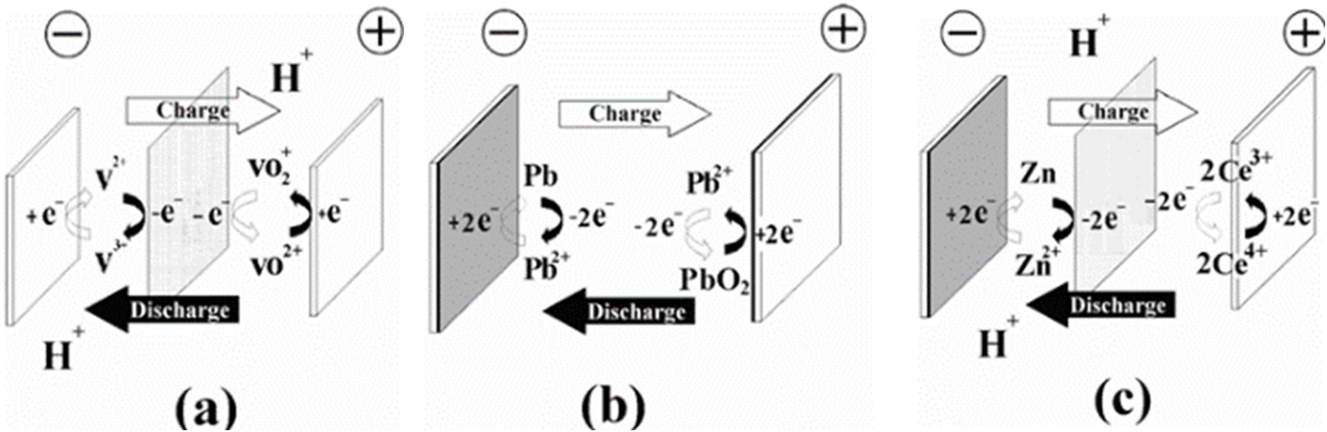 | ||
| Fig. 2 Types of redox flow battery, according to the nature of energy storage. Energy is stored (a) in the electrolytes, (b) in the active material within the electrodes, and (c) hybrid (in both electrode and electrolyte phases). Reproduced from ref. 32 with permission from Royal Society of Chemistry, copyright 2012. | ||
In addition to having a high energy density, slurry RFBs are not restricted by the low solubility of active species, but they increase electrolyte viscosity and do not perform well at high currents.38 RFBs present several benefits for energy storage systems ranging from 10 kW to 10 MW. These advantages include improved affordability, portability, adaptability, discharge capacity, quick responsiveness, and enhanced safety features when contrasted with lithium-ion and sodium–sulfur battery technologies.39 As early as 1974, Thaller invented the first flow battery based on CrII/CrIII and FeII/FeIII redox couples.40 There are several different types of RFBs, but the most common is all-liquid RFB, which dissolves both the charged and discharged electroactive materials into the water to form anolytes (negolytes) and catholyte (posiolytes).10 Hybrid RFBs are those whose half-cell reactions involve the deposition of solid species (usually charged forms) on electrodes or which contain gaseous materials (e.g., hydrogen) (Fig. 3a and b). In solid electrolytes, metals (e.g., Zn, Fe) are deposited on anodes and metal oxides (e.g., PbO2) are deposited on cathodes. Although electrode designs should be adjusted according to the deposition process, such RFBs perform similarly to all-liquid RFBs. Metal deposition electrodes encounter limitations in capacity and power density due to the formation of metal dendrites when subjected to high current densities. Consequently, unlike fully liquid RFBs, these systems do not completely decouple power and energy.41 Researchers have introduced a semiflow design to reclaim this critical advantage of RFBs and enhance energy density. In this configuration, an electroactive material is either deposited on conductive particles or formulated as a slurry. This material can subsequently be circulated through an electrochemical cell and stored externally outside the stack (Fig. 3c).
 | ||
| Fig. 3 Schematics of a hybrid RF cell with a solid anode (a), a gas cathode (b), and a semiflow cell (c). Reproduced from ref. 10 with permission from the American Chemical Society, copyright 2015. | ||
Alternative emerging RFBs also garner substantial attention due to their distinctive design and associated advantages. Examples of these technologies include membrane-less RFBs and metal–air RFBs, which may represent promising energy storage devices owing to their potential for higher energy densities and lower costs than first-generation RFBs.37 Metal–air RFBs have a much higher theoretical energy density (in the range of 1100–1300 W h kg−1) compared to conventional lithium-ion batteries, which typically have a theoretical energy density of around 450 W h kg−1. This makes metal–air batteries a promising alternative for energy storage applications, particularly in sectors where high energy density is critical, such as electric vehicles and portable electronics.42 Metal–air batteries use pure metals such as calcium (Ca), magnesium (Mg), iron (Fe), aluminum (Al), lithium (Li), and zinc (Zn) as the anode material. The cathode consists of oxygen from the air, which is accessed through the battery's open-cell structure. The open design allows the battery to continuously interact with atmospheric oxygen, making the cathode reaction essentially “inexhaustible,” as oxygen is abundant in the atmosphere.43 This makes them attractive for applications where weight and energy capacity are crucial, like in electric vehicles or other portable energy sources. During the discharge cycle, atmospheric oxygen is reduced at the cathode, and this leads to the formation of metal oxides or peroxides. This reaction is what enables the battery to store and release energy during charge and discharge cycles.44 While the membrane-free cell design offers cost benefits, it still faces challenges related to PbO2 plating, Pb dendrites, and side reactions. Removing the membrane in flow batteries or fuel cells creates a fluid–fluid interface where selective ion exchange must occur with minimal reactant crossover. Various membraneless designs have been studied independently, necessitating the consideration of each cell design's results in the context of others. The performance decrease observed in ion-exchange membrane (IEM) free designs and the expense of alternative separators should not lead to compromises that undermine the initial purpose of considering a membraneless option. Consequently, there is a critical need for well-defined performance metrics to compare different designs effectively.
2.1. General parameters of flow batteries
A number of factors affect the electrical performance of the battery, and the following benchmarks can be used to measure that performance. Electrolytes have a volumetric capacity, which indicates how much charge can be stored within them [eqn (1)]. It is possible to dissolve redox-active materials, but particles, gases, or ionic liquids may also be used. In this respect, the volumetric capacity is a function of the amount of redox-active material and the electrons involved in the redox process, and the most typical unit to measure volumetric capacity is A h L−1. The energy density is calculated by W h L−1, including the voltage between the redox couples [eqn (2)].
 | (1) |
| E = C × U | (2) |
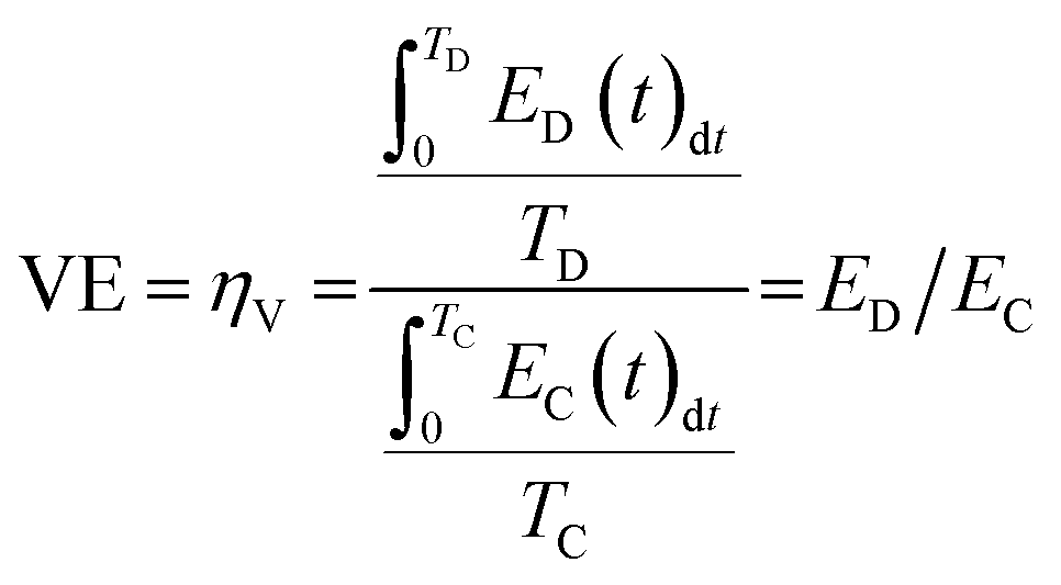
A battery's charging and discharging duration is directly influenced by the current density, which is associated with the electrochemical cell's membrane surface area. A commonly employed unit of measurement is mA cm−2. This unit can be converted to power density when voltage is considered, expressed as mW cm−2. Two key indicators of an FBs electrical performance are coulombic efficiency (CE) and voltage efficiency (VE). The CE, known as faradaic or current efficiency, measures the relationship between the charge applied during the charging process and the charge retained during the discharging process within the same charge/discharge cycle [eqn (3)]. CE below 99% suggests either the migration of redox-active substances through the membrane to the opposite half-cell or the occurrence of irreversible side reactions involving the redox-active material or the electrolyte itself, such as the generation of hydrogen (eqn (4) and (5)).
 | (3) |
 | (4) |
| EE = ηEE = ηCηV | (5) |
A hybrid capacitor achieving 100% CE does not necessarily demonstrate reversible electrochemical reactions. Specifically, when CE falls below 99%, it may suggest the occurrence of irreversible parasitic side reactions, such as the breakdown of electrolytes or electrodes, or the reaction of contaminants outside the proper operating voltage range. These issues can lead to diminished electrochemical performance, including reduced device lifespan or increased self-discharge.45 Furthermore, energy dissipation losses are inevitable in the system due to factors like electrolyte concentrations, operating temperatures, or redox reactions involving electrolyte components. Consequently, attaining 100% EE is challenging.45 The VE is calculated by dividing the average voltage during discharge by the average voltage during charge under constant current conditions, as shown in eqn (4). There is a variety of over potentials contributing to the difference between these discharge and charge voltage values. It is crucial to consider diffusion, polarization, and ohmic over potential when it comes to FBs.14 It is notable that the current density increases when the voltage efficiency decreases. When CE and VE are multiplied, the energy efficiency is obtained, which measures how much energy is applied and retained [eqn (5)]. A typical RFB's EE value ranges from 50 to 90 percent, depending upon the applied current density and material quality.46,47 This finding indicates that the VRFB is capable of maintaining stable performance over a wide temperature range (10–40 °C), with electrolyte conditions optimized for charge/discharge behavior. Specifically, with a vanadium concentration of 2.0 M and sulfate concentration of 5.5 M, the battery can operate efficiently across a significant state-of-charge (SOC) range (0–90%). Moreover, the EEs remains steady at 75–80%, which suggests that the VRFB can maintain its energy efficiency even in fluctuating temperature conditions. This is important for improving both energy density and operational stability over a broader range of temperatures. The key takeaway is that by controlling the SOC, the VRFB can optimize its performance, making it a versatile option for large-scale energy storage systems, especially in environments with varying temperatures.48
3. Types and overview of energy storage system
A storage solution that is economically convenient and technologically competitive must ensure the ability to respond quickly and store enough energy to meet both the requirements of the generation and grid, as well as to last a long time and endure multiple charge/discharge cycles. In the modern era, technology is characterized by varying levels of sophistication and can handle varying storage and localization requirements.30 Energy can be stored in many ways: mechanically, electrochemically, chemically, electromagnetically, thermally, and so on.49,50 However, energy storage technologies can be classified as those that store energy for a short period ones that respond quickly. In addition, those that perform well for electric energy applications, the best storage systems for electric energy applications, can be found in Table 2 and described below, while design and operating characteristics are listed in Table 3.| Technology | Top power [MW] | Top energy [MW h] | Energy density [W h kg−1] | Discharge time | Response time | Round-trip efficiency | Cycle life 103 | Capital cost [k$ per kW] | Capital cost [$ per kW per h] |
|---|---|---|---|---|---|---|---|---|---|
| PHES | 3000 | 104 | 0.3 | 101 h | min | 70–85% | 20 | 0.4–5.6 | 10–350 |
| CAES | 300 | 103 | 10–30 | 10–101 h | min | 60–75% | 30 | 1.7 | 150–350 |
| TES | 20 | 101 | 70 | h | min | — | 10 | — | 5000 |
| FES | 20 | 5 | 11–30 | min | ms | 85% | 101–102 | 2.3 | 2400 |
| SMES | 100 | 101–103 | — | min | ms | 90–95% | 10 | 2 | 10![[thin space (1/6-em)]](https://www.rsc.org/images/entities/char_2009.gif) 000 000 |
| EDLC | 100 | 10−2 | 10–30 | s | ms | 95% | 500 | — | 4600 |
| ECES | 10–40 | 10–101 | 25–50 | 10 h | ms | 75–85% | 3 | 4.6 | 130 |
| Sodium–sulfur | 34 | 101 | 150–120 | 10 h | s | 85–90% | 4.3–6 | 3.5 | 550 |
| Sodium–nickel chlorine | 1 | 6 | 90–120 | 10 h | s | 855 | 3–4 | 3.5 | 650 |
| Lithium-ion | 16 | 20 | 100–200 | 10 h | ms | 95% | 4–8 | 3–4 | 600 |
| Electrolyzer/fuel cells | 1 | 10 | 800–1300 | 10 h | ms | 35–45% | 50 | 17 | 10000 |
| RFB | 2–100 | 6–120 | 10–50 | 10–101 h | ms | 85% | 13 | 3.2 | 900 |
| Technology | Scalability | Flexibility (F) | Independency (W–W h) | Environmental impact (GIS) |
|---|---|---|---|---|
| a GIS: geographic information systems. | ||||
| PHES | Low | Low | Yes | High |
| CAES | Low | Low | Yes | High |
| TES | Low | Low | Yes | Mild |
| FES | High | Good | Yes | Low |
| SMES | Good | Low | No | Low |
| EDLC | Low | Low | No | Low |
| ECES | Good | Low | No | Low |
| Sodium–sulfur | Good | Good | No | Low |
| Sodium–nickel chlorine | Good | Good | No | Low |
| Lithium-ion | High | Good | No | Low |
| Electrolyzer/fuel cells | High | High | Yes | Low |
| RFB | High | High | Yes | Low |
3.1. Pumped hydro energy storage (PHES)
Since variable solar and wind energy are being deployed in large quantities, storage is becoming crucial in electricity systems. A total of 99% of the volume and 96% of the capacity of global storage energy comes from pumped hydro energy storage. Most electricity storage market shares are occupied by batteries, including batteries for utility vehicles, home appliances, and electric vehicles. PHES systems have power capacities ranging from 1 to 3000 MW, with efficiency levels between 76–85%. These systems boast an exceptionally long lifespan, typically 50 years or more, and can undergo virtually unlimited charge–discharge cycles.51 Despite being a well-established technology, PHES faces several challenges, including site-specific social constraints, substantial initial investment, extended construction timeframes, concerns about wildlife habitat preservation, and a response time of 10 to 15 minutes compared to the other ESS.52 Additionally, the size of PHES facilities presents a significant limitation, as they cannot be scaled down to smaller dimensions like some newer energy storage technologies. There is a rapid decline in the price of batteries, making them more competitive with pumped hydro for short-term storage (minutes to hours). Despite its high cost, pumped hydro continues to be much cheaper for storing large quantities of energy (over several hours to weeks).30,53 Table 3 illustrates that the PHES has the highest power and energy rating, extended lifetime, and the lowest discharge losses of any power supply. In wind power integration, the PHES primarily provides energy management based on time-shifting and frequency control. In addition to its slow response, the PHES impacts the natural environment due to its lack of suitability for suppressing wind fluctuations.49 As an example, PHES has the most significant environmental impact due to its requirement for extensive infrastructure (200 meter scale), specific geographical features, and the potential for partial replacement by battery storage in areas where large-scale PHES is not feasible due to location limitations.54 However, it can also address the shortcomings of battery storage, such as high self-discharge rates, frequent replacement needs, elevated maintenance expenses, and memory effect (diminished discharge capacity).55 The future expansion of PHS is constrained by limited geological suitability and adverse environmental consequences.56 In Fig. 6, China has the most hydropower capacity, followed by the European Union, Brazil, and the United States.53 Among renewable energy sources, solar and wind stand out as the most plentiful, advanced, cost-effective, and widely accepted options. There has been a steady increase in the installed capacity of solar and wind systems, with or without pumped hydroelectric energy storage (PHES), as evidenced by comprehensive experimental and/or simulation results.57 The continuous growth in the deployment of solar, wind, and PHES technologies since 2010 demonstrates their technical and economic feasibility. However, the unpredictable nature of solar and wind power poses challenges to system reliability.58 To enhance grid stability and mitigate the negative effects of fluctuating renewable energy output, energy storage has emerged as a viable solution, particularly for off-grid and remote power supply applications.593.2. Compressed air energy storage (CAES)
In the 19th century, the CAES was developed and used for various industrial applications. It is possible to compress air using electrical compressors and store it underground (salt caverns, abandoned mines, rock structures) or above ground (vessels, pipes). A modified gas turbine burns and expands compressed air mixed with natural gas when needed.49 Traditional CAES systems face challenges related to fossil fuel use and carbon emissions. To address this, researchers have developed advanced adiabatic CAES systems that incorporate thermal storage, eliminating the need for combustion in electricity generation.60 However, CAES technology is constrained by the requirement for specific geographical locations to house air storage tanks or underground caverns. Recent innovations propose using high-pressure, above-ground carbon fiber tanks for air storage in small and medium-scale advanced adiabatic CAES systems, helping to overcome this limitation.61,62 Another potential solution involves implementing decentralized small-scale CAES systems. These systems consist of multiple installations functioning as a virtual large power plant, managed by a central distribution unit.63 This approach offers a potentially more cost-effective alternative to conventional CAES technology. This approach will remove the need for specific geological conditions and allow air compression at higher pressures. These advanced CAES systems offer energy management capabilities similar to PHES.30 Each ESS is capable of meeting a diverse range of applications, based on the key technical parameters. For example, energy management requires very high capacities in power and energy ratings, and these can be met by PHES, CAES, FC, VRFB, and TES (Table 2).64,65 Compared to lead–acid batteries, CAES is the cheapest energy storage system, costing approximately half as much as other systems.66 The varying impact profiles of assessed technologies like CAES suggest that a diverse mix of technologies may yield superior overall performance when evaluated collectively. The key challenge lies in striking a balance and optimizing the impacts associated with infrastructure against those related to the combustion of fossil fuels.67 Conducting an analysis that extends beyond greenhouse gas emissions and climate change mitigation would offer valuable insights into the potential development of an electricity generation system with minimal environmental consequences.68,693.3. Thermal energy storage (TES)
The TES system is essential for creating an effective solar energy apparatus. Concentrating solar power (CSP), plants are recognized for their potential to extend electricity generation periods through the use of thermal energy storage systems. There is significant interest in enhancing TES capabilities within CSP facilities.70 While photovoltaic (PV) systems typically store electrical energy as chemical energy in batteries,71 CSP technology employs TES to preserve solar energy in the form of thermal energy. Numerous studies have been conducted to evaluate various energy storage technologies.72 In solar thermal applications, there is often a discrepancy between energy supply and demand due to solar radiation's inconsistent and unpredictable nature. An adequately designed TES system can mitigate this drawback by ensuring a steady energy supply to the consumer.73 In solar power tower systems, thermal storage is utilized for grid applications to achieve time shifting, which involves postponing energy delivery to a turbo-alternator and its subsequent conversion into electrical energy.70 These systems are well-suited for energy management services due to their characteristics of high power output, substantial energy capacity, and gradual response times.30 TES technologies are classified into two categories based on the operating temperature of the energy storage material: low temperature TES and high temperature TES.72 Low temperature TES is more appropriate for applications requiring high power density, such as load shaving, industrial cooling, and future grid power management. In high temperature TES systems, sensible heat and latent heat storage methods are the most significant. Sensible heat storage systems store thermal energy by changing the temperature of the storage medium without any phase change occurring in the material. The storage capacity of sensible heat systems is determined by the specific heat and mass of the storage medium, which can be in various forms, including liquids (water, molten salt, or thermal oil) or solids (concrete, stone, metal, or ground).74 A major drawback of sensible heat storage systems is their substantial space requirements.64 The ecological effects of three TES systems currently employed in high-temperature CSP plant applications. The systems under investigation include: one that utilizes high-temperature concrete for sensible heat storage,75 another that stores sensible heat in molten salts,76 and a third that also uses molten salts but for latent heat storage.77 To facilitate comparison, these systems are standardized despite their initial differences in storage capacity. The environmental impact is evaluated by determining the embodied energy in each TES system's components. Among the three, the concrete-based sensible heat storage system demonstrates the lowest environmental impact. In contrast, the molten salt and Phase Change Material (PCM) systems exhibit higher embodied energy values, primarily due to the nitrate mixture used as the storage medium.78 Fig. 4 shows the comparison between steel rotor FESSs and composite rotor FESSs in terms of life cycle emissions of GHGs.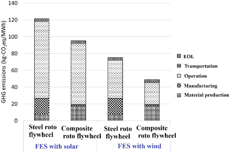 | ||
| Fig. 4 Life cycle GHG emissions of FES. Reproduced from ref. 83 with permission from Elsevier B.V., copyright 2021. | ||
3.4. Flywheel energy storage (FES)
Kinetic energy storage, also called flywheel energy storage, is a mechanical method of storing energy that effectively ensures smooth machine operation and delivers high power and energy density. The process involves transferring kinetic energy into and out of the flywheel using an electric machine, which functions as either a motor or generator, depending on whether it's in charge or discharge mode. Due to their superior efficiency, high power density, and minimal rotor losses, permanent magnet machines are typically employed in flywheel systems.79,80 The energy stored in a flywheel depends on the rotor's moment of inertia, rotational speed, tensile strength, and stress limitations. These characteristics categorize flywheels into two types: low-speed steel FES systems, which operate at up to 10k rotations/60 s, and high-speed FES systems, capable of reaching 100k rotations/60 s. The latter are constructed using advanced composite materials like carbon fiber.81,82 Despite their impressive power density of about 2000 W kg−1, low-speed FES systems have a modest energy density of approximately 5 W h kg−1. They experience significant self-discharge due to idling losses during standby mode. Consequently, these systems are primarily utilized in power quality applications requiring brief periods of high power and frequent charge–discharge cycles. In contrast, high-speed FES systems boast both elevated power density and superior energy density, reaching up to 200 W h kg−1. However, their widespread adoption is hindered by the high costs associated with advanced composite materials, limiting their use to specific long-term storage applications.64 FES systems face challenges with significant standby losses, experiencing approximately 20% capacity reduction every hour due to self-discharge. These systems are vulnerable to unexpected dynamic loads or external shocks, which can result in system failure.36 FES technology is not yet considered fully mature and requires additional research and development across various aspects of its rotating components.36 Furthermore, FES systems are expensive and have not achieved widespread commercial success.72 Assessing the life cycle environmental performance of FES for utility-scale applications is crucial for identifying areas of improvement, making sustainability-focused decisions, comparing with alternative EST, and shaping environmental policies in the energy sector.83 The FES with composite rotors demonstrates superior environmental performance and lower greenhouse gas (GHG) emissions compared to those with steel rotors. When charged using solar energy, the life cycle GHG emissions for steel rotor FESS and composite rotor FESS are 121.4 kg-CO2 eq. MW−1 h−1 and 95.0 kg-CO2 eq. MW−1 h−1, respectively. In contrast, when charged using wind energy, the emissions are 75.2 kg-CO2 eq. MW−1 h−1 for steel rotor FES and 48.9 kg-CO2 eq. MW−1 h−1 for composite rotor FESS. This variation is attributed to the difference in upstream GHG emissions between solar and wind-based electricity, with solar producing 48 kg-CO2 eq. MW−1 h−1 and wind generating 11 kg-CO2 eq. MW−1 h−1.84 Fig. 4 shows the comparison between steel rotor FES and composite rotor FES in terms of life cycle emissions of Green House Gases (GHGs).3.5. Superconducting magnetic energy storage (SMES)
Energy storage in the SMES system occurs through a magnetic field generated by a direct current (DC). This system utilizes an inductor, which is kept under specific conditions to achieve superconductivity, allowing for the creation of a powerful magnetic field as current passes through it.49 A typical SMES consists of three main parts: a superconducting coil unit, power conditioning, and cryogenic subsystem.85 To exchange power between the AC system and the superconducting coil, the PCS is crucial. The selection of coil configuration should be based on the intended SMES rating. Solenoid and toroid are the two most common superconducting coil arrangements.86 For micro and medium-scale applications, solenoid coil configurations are typically preferred due to their low mechanical stress and high stray magnetic field. However, large-scale SMES systems generate strong magnetic fields, making toroid arrangements more suitable for their lower stray magnetic field compared to solenoids. Additionally, toroid configurations require less space and use shorter wire lengths, making them more cost-effective. Fig. 5 illustrates both pancake-type solenoid coil and segmented toroid-type coil arrangements.87 When designing an SMES system, factors such as intended use, cost, space constraints, and manufacturing feasibility should be considered to determine the appropriate structure. The solenoidal design offers advantages in terms of ease of construction and improved management of mechanical stresses, primarily due to its reduced wire requirements.88 They are being developed for power quality assurance and sag compensation, with top power around 10 to 1000 MW, and they should be ready by 2030–2040.30 The primary purpose of these SMES systems is to enhance power stability. The initial Low-Temperature Superconducting (LTS) SMES was created by Los Alamos National Laboratory (LANL) to mitigate power fluctuations.89 In Japan, several medium and small-scale LTS-SMES units were developed specifically for addressing voltage sag and short-term voltage stability issues.90 Additionally, Japan produced a 2GJ-2 G High-Temperature Superconducting (HTS) SMES to stabilize frequency and compensate for load variations.91 China also contributed by designing small and medium-scale SMES systems to improve voltage stability92 and counteract power oscillations.93 Meanwhile, Korea focused on developing SMES technology for enhancing power quality94 and overall power system stability.95 | ||
| Fig. 5 Superconducting coil arrangements (a) solenoid (b) toroid. Reproduced from ref. 87 with permission from Elsevier B.V., copyright 2019. | ||
The SMES system faces significant challenges due to its intricate cooling mechanism and substantial initial investment costs. The superconducting coil's stability is compromised by its sensitivity to temperature fluctuations and critical magnetic field changes. While LTS SMES technology has reached commercial viability, HTS SMES remains underdeveloped and not fully established as a mature technology.96 Firms engage in environmental practices to mitigate the ecological impact of their operations, products, and services. These initiatives encompass various activities such as reducing waste, conserving resources, implementing recycling programs, and offering eco-friendly or organically produced goods.97,98 The concept of environmental practices is intricately linked to other related ideas, including sustainable development, sustainability, and environmentally conscious entrepreneurship99 Using these criteria, an appropriate Energy Storage System (ESS) can be chosen for the desired power system application.100 The selection process considers various system preferences and design parameters, including ESS maturity, capacity (both energy and power density), storage duration, standby time, response time, lifecycle count, storage economics, energy losses, conversion efficiency, thermal specifications, safety considerations, intended use, automation compatibility, mobility, and environmental impact.101,102
It's rare for a single ESS to excel in all these characteristics simultaneously. Therefore, the optimal ESS technology is typically determined based on capacity requirements and maximum discharge duration. Tables 2–4 provide a comparative analysis of various ESS technologies, evaluating their technical and economic attributes. RFBs are more electrochemically stable and have a larger potential window in organic aprotic solvents than protic solvents like water. Battery capacity can be increased when redox couples are used with elevated voltages. It is important to note, however, that the ion conductivities in organic solvents are much lower, which limits the amount of current that can be used. By increasing the voltage (power density), this effect is partially mitigated (Table 5).14,109
| System | Rating | Density | Response time | Efficiency (%) | Self-discharge per day (%) | ||
|---|---|---|---|---|---|---|---|
| Power rating (MW) | Discharge time typical | Power density (W l−1) | Energy density (W h l−1) | ||||
| PHES | 100–5000 | 1–24 h+ | 0.1–0.2 | 0.2–2 | min | 70–80 | Very small |
| CAES | 5–300 | 1–24 h+ | 0.2–0.6 | 2–6 | min | 41–75 | Small |
| FES | 0–0.25 | s–h | 5000 | 20–80 | <s | 80–90 | 100 |
| LA | 0–20 | s–h | 90–700 | 50–80 | <s | 75–90 | 0.1–0.3 |
| NiCd | 0–40 | s–h | 75–700 | 15–80 | <s | 60–80 | 0.2–0.6 |
| Li-on | 0–0.1 | min–h | 1300–10000 | 200–400 | <s | 65–75 | 0.1–0.3 |
| NaS | 0.05–8 | s–h | 120–160 | 15–300 | <s | 70–85 | −20 |
| VRB | 0.03–3 | s–10 h | 0.5–2 | 20–70 | <s | 60–75 | Small |
| ZnBr | 0.05–2 | s–10 h | 1–25 | 65 | s | 65–75 | Small |
| FC | 0–50 | s–24 h+ | 0.2–20 | 600 (200 bar) | s | 34–44 | 0 |
| SC | 0–0.3 | ms–1 h | 40000–120000 |
10–20 | s–min | 85–98 | 20–40 |
| SMES | 0.1–10 | ms–8 s | 2600 | 6 | <s | 75–80 | 10–15 |
| ESS type | Energy density (W h kg−1) | Discharge time (h) | Response time | Round trip efficiency | Life cycles |
|---|---|---|---|---|---|
| Lead–acid | 25–50 | 1–2 | ms | 75% | 800 |
| Na–S | 120–150 | 2–6 | ms | 89% | 4500 |
| Na–Ni-Cl | 95–120 | 0.5–2 | ms | 90% | 4500 |
| Li-ion | 200–300 | 1 | ms | 87% | 4000 |
| FCs | 800–1300 | >10 | ms | 24% | 300 |
| VRFB | 25–30 | >10 | ms | 75% | 20000 |
3.6. Supercapacitors
It is mostly electric double layer capacitors, such as supercapacitors (SC), which assist other power supplies in handling surge power requirements, particularly in electric and hybrid vehicles. The SC boasts exceptional cycle stability and remarkably high power density. Its ability to charge and discharge rapidly stems from its unusually low internal resistance. Additional benefits include robustness, high dependability, zero maintenance requirements, extended lifespan, and the capacity to function across a broad range of temperatures and in various settings. These eco-friendly devices can be easily recycled or neutralized without harmful effects.49 Like FES, the round-trip efficiency of EDLCs is high for short discharge periods but decreases over longer durations due to internal losses that gradually deplete the capacitors. As a result, EDLCs are primarily utilized in grid applications for rapid services such as sag compensation. Although both SMESs and EDLCs are costly, EDLCs require virtually no maintenance, while SMESs need minimal servicing. Nevertheless, the expenses associated with EDLCs are continuously declining as new manufacturers enter the market.1033.7. Electrochemical energy storage (ECES)
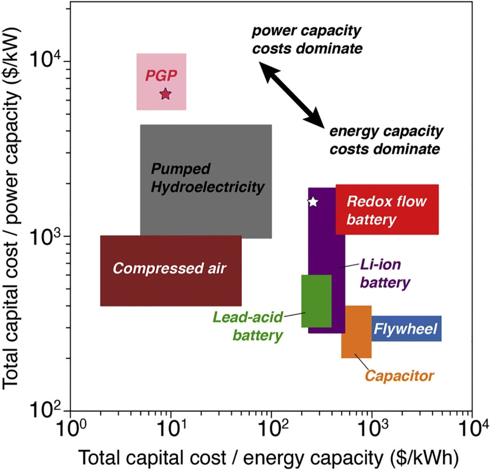
The aforementioned storage technologies possess distinct characteristics, each with advantages and disadvantages. Currently, only PHES, CAES, and TES are suitable for long-duration (hours) grid energy storage. In contrast, FES, SMES, and EDLC operate at low to medium power levels and exhibit rapid response times, but are effective only on the second-to-minute timescale and are presently cost-prohibitive. The final technology presented for energy storage is ECES, to which the subsequent portion of this state-of-the-art review will be dedicated. The ECES represents one of the most prevalent solutions widely employed across various industries, and the development of related technologies is highly dynamic. Diverse classifications of electrochemical energy storage can be found in the literature.104 It is most commonly stated that electrochemical energy storage encompasses accumulators (batteries), capacitors, SC, and fuel cells.105 A distinctive characteristic of ECESs is that in the majority of cases, deep discharges significantly impact battery longevity. Consequently, manufacturers specify a depth of discharge (DOD) less than 100%, to which the nominal cell lifespan is referenced. It is defined as the number of cycles during which the cell capacity (i.e., the deliverable charge) does not decrease below a specified percentage (e.g., 60%) of the nominal capacity (expressed in A h). In practical applications, only a portion of the ES in most ECES devices is utilizable, and this portion is subject to decrease over time. Another characteristic of most ECES, which is also shared with SMES and EDLC, is that the same device provides both power conversion and energy storage. This feature allows for highly compact systems but simultaneously links power to energy sizing.30 With these features, renewable energy sources can generate electricity to a wide range of operating power and discharge time (Fig. 7). Fig. 6 illustrates those technologies with power limitations are positioned in the upper left section, while those constrained by energy are located in the lower right. For each storage technology, a box is used to represent the range of total capital costs per unit of capacity, as determined by the available data (Fig. 8).106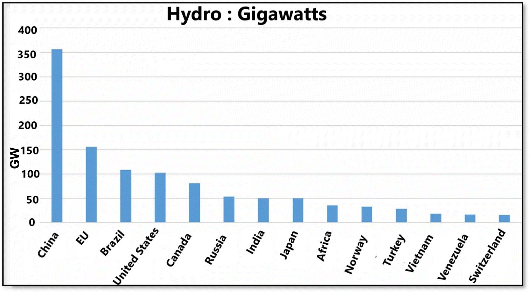 | ||
| Fig. 6 Hydropower capacity (Gigawatts) for selected countries and regions in 2021. Reproduced from ref. 53 with permission from the IOP science, copyright 2021. | ||
 | ||
| Fig. 7 Power-duration diagram of ES. Reproduced from ref. 30 with permission from Elsevier B.V., copyright 2014. | ||
 | ||
| Fig. 8 Long- and short-duration energy storage technology capital costs by capacities. Reproduced from ref. 106 with permission from Joule, copyright 2020. | ||
3.8. Comparison of energy storage technologies
Unlike other electrochemical energy storage systems, RFBs and Fuel Cells (FCs) separate power conversion from energy storage, enabling independent sizing of power and energy components. This characteristic allows for almost limitless capacity by simply increasing the size of storage tanks. In practical terms, the energy capacity of current designs ranges from 102 to 107 W h, surpassing most Electrochemical Energy Storage Systems (ECES) by at least one order of magnitude. When storage durations exceeding 4–6 hours are necessary, RFBs and FCs offer more benefits compared to alternative electrochemical devices.30 Lithium ion batteries (LiBs) have become the dominant technology in the market due to their exceptional performance and substantial cost reductions. However, a FB, now offered by multiple manufacturers at the required scale, present a different approach. This technology boasts lower variable costs ($ per kW per h) and utilizes a broader SOC range. Nevertheless, it comes with drawbacks, including lower efficiency compared to LiBs and relatively high fixed costs ($ per kW).107 From an engineering standpoint, VRFB systems offer numerous benefits. One key advantage is their exceptional safety profile, which is crucial for ES and thermal regulation. The circulation of electrolytes effectively dissipates heat generated within the cell stack. Moreover, the distinctive configuration of these systems streamlines the manufacturing process. By modularizing components such as stacks, electrolyte containers, plumbing, and electrical systems, VRFB technology reduces complex and costly production steps. Additionally, the rebalancing procedure in VRFB systems is straightforward.108FB offer several additional benefits, including: the ability to handle high overloads for brief periods, millisecond response times, minimal self-discharge when stored in sealed tanks, operation at room temperature, extended charge and discharge cycles, and high round-trip efficiency.64
3.9. Redox flow batteries (RFB)
RFBs are one of the newest and most promising technologies in electrochemical systems for stationary energy storage. These devices function as electrochemical energy conversion systems, utilizing redox processes of liquid-state species stored in external tanks and introduced into the RFB as needed. In this sense, an RFB shares similarities with a polymer electrolyte membrane fuel cell (PEMFC) and can be classified as a type of fuel cell. The key advantages of this technology include adaptability and scalability, separate sizing of power and energy components, high round-trip efficiency, significant depth of discharge, high DOD, extended lifespan, quick response times, and minimal environmental impact.30 Consequently, it is essential to assess the environmental impact from the extraction of resources to the point before consumer transportation, known as cradle-to-gate analysis. The preferred method for this evaluation is life cycle assessment (LCA). To assess the commercial viability of the current technology, we have incorporated both LCA studies and levelized cost of storage (LCOS) analyses.11 As a result of these features are ideal for assisting renewable energy generation into the grid, providing a wide range of operating powers and discharge times (Fig. 9). | ||
| Fig. 9 Principle of advanced RFBs including redox species, electrode, and membrane. Reproduced from ref. 6 with permission from Cell Press, copyright 2019. | ||
 | ||
| Fig. 10 Schematic diagram of the RFB. Reproduced from ref. 31 with permission from Royal Society of Chemistry, copyright 2015. | ||
1. Tanks: separate tanks store the anolyte and catholyte solutions. The size of these tanks can influence the system's capacity and energy storage.
2. Pumps: pumps are used to circulate the electrolytes through the system. They ensure a steady flow of the anolyte and catholyte to and from the cell stack, facilitating the redox reactions.114
3. Cell Stack: the heart of the RFB, where the electrochemical reactions occur. It consists of:
○ Electrodes: typically made from materials like carbon or other conductive materials, these facilitate the transfer of electrons during the redox reactions.
○ Membrane: a selective barrier that separates the anolyte from the catholyte, preventing mixing while allowing the passage of ions. Common materials for membranes include Nafion and other ion-exchange membranes.115
3.9.2.1. Redox reactions. • In the anolyte, oxidation occurs, releasing electrons.
• In the catholyte, reduction takes place, consuming electrons.
This separation and the movement of ions through the membrane allow the battery to function efficiently while maintaining the integrity of the electrolyte solutions. The overall design supports scalability, flexibility in energy capacity, and the potential for long cycle life.116
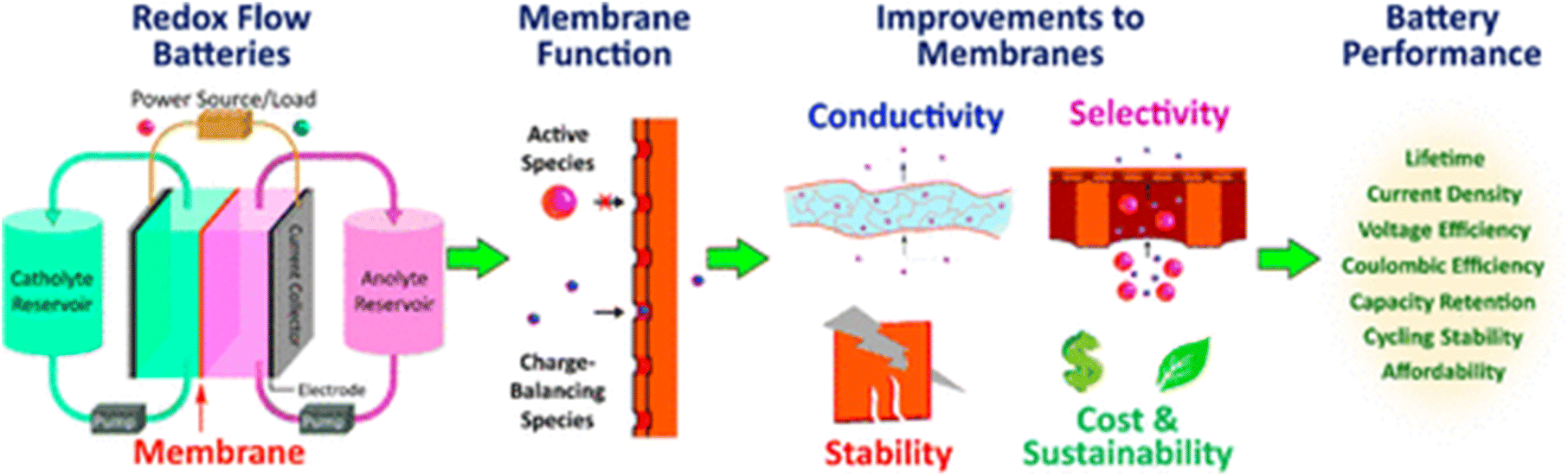 | ||
| Fig. 11 A RFB membrane allows ions to pass through, but isolates redox-active species. Batteries will perform better with improved membranes. Reproduced from ref. 117 with permission from the American Chemical Society, copyright 2020. | ||
The wide range of active species in RFBs necessitates careful consideration of multiple factors when designing membranes. For example, while PFSA membranes demonstrate excellent conductivity in the acidic environments of VRFBs, they show reduced conductivity in other RFB types that require alkaline conditions.118 The variety of RFB designs presents both challenges and opportunities for membrane development, and the diverse user requirements (such as low initial costs or high power density) make it challenging to draw broad conclusions across all RFB types. As an illustration, PFSA membranes typically exhibit ionic conductivities in the range of tens of mS cm−1 when vanadium crossover is a significant issue,119,120 whereas swollen PFSA membranes can achieve conductivities up to thousands of mS cm−1 in situations where increased anion passage is beneficial.121
The performance and durability of RFBs can be significantly influenced by membrane characteristics. The migration of active species across the membrane results in self-discharge122 and diminished coulombic efficiency (CE), which is calculated as the ratio of discharge to charge capacity within a single cycle.123 Additionally, optimal cell performance requires maximizing the conductivity of charge-balancing ions. The voltage efficiency (VE), defined as the ratio of discharge to charge voltage, is linked to the membrane's ionic conductivity. Higher ionic conductivity in membranes is preferred as it enables greater power densities.124 Beyond impacting cell efficiencies, membrane issues can also trigger cell failures.125 Separators must possess sufficient mechanical strength to endure operational pressures and flow rates, as well as withstand the harsh chemical environments within RFBs, including highly oxidizing conditions and often extreme pH levels, which can cause chemical degradation of the membrane.126
Nafion ion exchange membranes are often considered the gold standard for numerous RFBs due to their high ionic conductivity and exceptional chemical durability.127 Nafion is a phase-separated perfluorosulfonic acid polymer (PFSA) whose acidic side chains and interconnected hydrophilic regions contribute to its high conductivity, while its hydrophobic perfluorinated backbone provides significant chemical resistance.128 Recent research has focused on more efficient membrane designs and alternative chemical compositions, exploring materials and morphology optimization strategies that could potentially reduce overall RFB costs by up to 40%.122 To effectively improve such membrane designs, it is crucial to comprehend the fundamental factors that contribute to the desired properties.
4. Inorganic electrolytes
4.1. All-vanadium based electrolyte
Vanadium-based electrolytes are indeed a cornerstone of RFB technology, particularly in VRFBs. The introduction of these electrolytes by Skyllas-Kazacos and Rychcik in 1988 marked a significant advancement in the field.130 In VRFBs, the active redox species is vanadium, which exists in multiple oxidation states. This allows the same vanadium-based redox active components to be used in both the catholyte and anolyte, which helps mitigate issues related to capacity fading arising from electrolyte cross-contamination—an essential advantage over other flow battery chemistries.11The electrolyte consists of two primary components:
1. Active redox material (solute): in the case of VRFBs, these are typically vanadium ions in different oxidation states (V2+, V3+, V4+, V5+).
2. Supporting material (solvent): a water-based solution is usually employed, often with sulfuric acid to enhance ion conductivity and solubility.
The design of VRFBs allows for scalability and long cycle life, making them particularly suitable for large-scale energy storage applications, such as integrating renewable energy sources. Their ability to maintain performance over time, thanks to the unique chemistry of vanadium, has made them a focus of ongoing research and development in energy storage technologies.131 Various vanadium compounds such as VCl3, VOSO4, and V2O5 have been explored to optimize RFB performance.6 Supporting solutions like H2SO4, HCl, and NaOH play a crucial role in influencing these electrolytes' solubility, conductivity, and stability. Each combination can affect the electrochemical behavior and overall efficiency of the battery; therefore, researchers continue to delve into these variations to find the ultimate formulations for improved performance. Absolutely, the choice of vanadium compounds and supporting solutions in RFBs has significant implications for performance and cost.
○ Merits: lower cost than other vanadium compounds, making it an attractive option for large-scale applications.
○ Demerits: its lower solubility can limit the achievable energy density, necessitating larger volumes of electrolyte.
2. VOSO4:
○ Merits: offers better solubility, which allows for higher concentrations of vanadium ions. This can enhance the energy density of the battery and improve overall efficiency.
○ Demerits: may be more expensive or less stable under certain conditions compared to V2O5.
3. VCl3:
○ Merits: provides an alternative redox chemistry that could be beneficial in specific applications.
○ Demerits: poor solubility and the production of Cl2 gas when using HCl as a supporting solution pose significant challenges, including safety concerns and potential efficiency losses.35
• Increased energy density: higher concentrations can store more energy in a smaller volume, making the system more efficient.
• Reduced costs: lower concentrations require larger tanks and more electrolyte, increasing the system's volume and cost.
Optimizing the combination of vanadium compounds and supporting solutions is critical for enhancing the performance and economic viability of VRFBs. Ongoing research explores these interactions to identify the best configurations for various applications. In a RFB, the circulation of the anolyte and catholyte between the storage tanks and the cell stack is indeed a crucial part of the design.
In vanadium oxidation states, VO2 signifies V4+, while VO2+ indicates V5+. Within RFBs, the positive electrode hosts redox reactions involving V4+ and V5+ as participate, whereas the negative electrode facilitates reactions with V3+ and V2+. It's important to note that any vanadium that crosses over to the positive electrolyte will be oxidized to VO2+. Conversely, excess vanadium in the negative electrolyte tends to be reduced to V3+.132
4.2. Electrochemical reaction mechanisms of VRFB
To enhance the EF of the VRFB, it is crucial to minimize voltage losses stemming from various polarization types, including activation, ohmic, and concentration polarization. The EF of the VRFB is heavily influenced by its electrochemical characteristics, as the efficiency loss related to activation polarization primarily occurs at the electrode level. Consequently, reducing these voltage losses to the greatest extent possible is essential for improving overall VRFB performance.133,134 To advance the development of electrodes for high-power density VRB stacks, it is crucial to gain a clear understanding of the mechanisms underlying the redox reactions at the electrodes. The current state of knowledge presents various mechanisms for the redox reactions of VO2+/VO2+ (in the catholyte) and V2+/V3+ (in the anolyte) at the electrode, drawing upon valuable research efforts conducted to date. The electrochemical reaction mechanisms of V4+/V5+ and V2+/V3+ redox couples can be described as follows.16| Catholyte: VO2+ + 2H+ ↔ VO2+ + H2O − e− E0 = 1.0 V vs. SHE | (6) |
| Anolyte: V3+ + e− ↔ V2+ E0 = −0.26 V vs. SHE | (7) |
Initial investigations into the V2+/V3+ and VO2+/VO2+ redox reactions were conducted by Sun and Skyllas-Kazacos.135 Subsequently, these researchers delved deeper into the reaction mechanisms, focusing on the impact of oxygen-containing functional groups on the carbon electrode surface. Their findings revealed that C–OH functional groups serve as active sites for VO2+ oxidation on the electrode surface.136 The process involves an ionic exchange between VO2+ ions from the catholyte and H+ ions from the carbon surface's phenolic groups, as illustrated in Fig. 12a, step 1. Subsequently, an oxygen atom from the carbonyl group is transferred to the VO2+ ions, forming VO2+ on the electrode surface, while an electron moves from VO2+ to the electrode via the C–O–V bond (Fig. 12a, step 2). The oxidation reaction concludes with another ion exchange, this time between the surface-formed VO2+ and H+ ions in the electrolyte (Fig. 12a, step 3). During reduction, these reactions proceed in reverse order. A comparable mechanism was proposed for V3+ reduction on the electrode surface, depicted in Fig. 12b. Extensive X-ray photoelectron spectroscopy (XPS) analysis revealed that enhanced cell performance correlated with an increase in oxygen-containing functional groups on the carbon electrode surface, particularly phenolic groups. These groups serve as active sites, catalyzing both the VO2+/VO2+ and V2+/V3+ redox reactions. Due to the fact that the active species in both tanks are vanadium-based, degradation problems related to cross-contamination of electrolytes are prevented, resulting in a very long life span of 10000–20000 chargings and dischargings.35,137
 | ||
| Fig. 12 The redox reaction mechanism proposed by Skyllas-Kazacos for (a) VO2+/VO2+ redox couple in catholyte, (b) the V2+/V3+ redox couple in VRFB. Reproduced from ref. 31 with permission from Royal Society of Chemistry, copyright 2015. | ||
4.3. Influence of temperature based conductivity, viscosity and stability
VFRB is typically utilized in outdoor environments and occasionally under severe weather conditions. Consequently, environmental factors can significantly influence the reaction kinetics, ultimately affecting the overall performance of RFB. Environmental temperature is generally accepted to substantially impact the vanadium salts, solubility, conductivity, and viscosity.138 The physicochemical and electrochemical properties of five types of vanadium electrolytes, namely V2+, V3+, V3.5+ (V3+:VO2+ = 1:1), V4+ (VO2+), and V5+ (VO2+), which are the most prevalent electrolytes present in VRFB systems, were investigated comprehensively by Shuibo Xiao et al.139 Across a wide temperature range (−35–50 °C). The effect of temperature on vanadium electrolyte conductivity was also examined. Fig. 13a illustrates the ionic conductivity (σ) of all mentioned vanadium electrolytes concerning temperature. The σ of all electrolytes increases as temperature rises. The conductivity hierarchy, from highest to lowest, is as follows: V(V) electrolyte, V(II) electrolyte and V(IV) electrolyte (which exhibit nearly identical conductivity across all tested temperatures), V3.5+ electrolyte, and V(III) electrolyte. Notably, this trend aligns with the proton concentration of the electrolyte, as depicted in the inset of Fig. 9a. Higher conductivity and elevated temperature facilitate charge transfer and enhance electrochemical activity.140
 | ||
| Fig. 13 (a) Impact of temperature on the conductivity; (c) impact of temperature on the viscosity139 and (b) solubility of different vanadium electrolytes; (d) Roubaix diagram showing the relationship of pH and voltage of the RFB for different redox pair. Reproduced from ref. 11 with permission from John Wiley & Sons Ltd, copyright 2024. | ||
A key characteristic of VRFB is the cyclic pumping of electrolytes through the battery (stack) during operation. Consequently, electrolyte viscosity plays a crucial role in determining electrolyte's even distribution within the battery and the pump's energy consumption. Research conducted by F. Rahman and M. Skyllas-Kazacos specifically examined the viscosity of the positive electrolyte, revealing that it increases in proportion to the concentration of vanadium(V) and sulfate.141 The viscosity of vanadium electrolytes is influenced by both temperature and concentration. Fig. 13b illustrates the relationship between solution viscosity (η) and varying temperatures for different electrolyte types. As the temperature rises, the viscosity of each electrolyte decreases. Notably, the viscosity at lower temperatures is significantly higher than at higher temperatures.139 That is a critical observation regarding the stability of vanadium ions in different temperature ranges. Previous research highlights that while high acid concentrations can enhance the stability of V(V) ions at elevated temperatures,142 they negatively affect the stability of V(II), V(III), and V(IV) ions at lower temperatures. This restricts the operational temperature window for VRFBs to 10–40 °C. To address this limitation and expand the operating temperature range to extreme conditions (−35 °C to 50 °C), the choice of a 1.5 M vanadium concentration is a strategic approach. This concentration can help maintain the stability of the electrolyte across a broader temperature range while potentially improving overall performance. Testing under these conditions can provide valuable insights into the feasibility and efficiency of VRFBs in varied environments. The findings regarding electrolyte stability at low temperatures offer crucial insights into the operational limits of VRFBs (Fig. 13b and d). At temperatures of −20 °C and −25 °C, all tested electrolytes demonstrate stability over 48 hours, indicating they can function effectively without issues like precipitation or freezing.
However, the situation changes at lower temperatures: the V(III) solution starts to precipitate within 24 hours at −30 °C, while the V(II) and V(III) solutions face immediate challenges at −35 °C, precipitating or freezing in under one hour. The V3+ mixed solution also shows instability, with precipitation occurring in less than 10 hours. The experiment demonstrates that the precipitation of V(II), V(III), and V3.5+ ions is reversible concerning temperature. When the solution is cooled, these vanadium species precipitate, but upon warming to 25 °C, they dissolve completely after 30 minutes, returning to their initial state. This behavior indicates that the precipitation process depends on temperature, highlighting the potential for reversibility in the system. Such thermally induced dissolution emphasizes the importance of temperature in controlling the solubility and phase behavior of vanadium compounds.139,143 As the SOC rises, conductivity increases and viscosity decreases, though these changes are not linear. The positive electrolyte exhibits its lowest electrochemical activity and reversibility at 50% SOC. Analysis of UV-vis and Raman spectra, along with excess spectra, reveals the formation of a mixed valence compound [V2O3(H2O)7]3+ in the V(IV) and V(V) electrolyte mixture, enhancing stability but reducing electrochemical performance. Within a 0–90% SOC range, a battery utilizing an electrolyte with 2.0 M vanadium concentration and 5.5 M sulfate concentration can function stably between −10 and 40 °C, maintaining an EE of 75–80%.48,144 In summary, extensive research is currently underway to enhance the solubility and thermal stability of vanadium-based electrolyte solutions. Studies have shown that 6 m of H2SO4 can dissolve 2 m of V2+ to V4+ and 3.5 m of V5+. While these concentrations exceed typical reported levels of vanadium salts, precipitation of electrolytes begins outside the 10–40 °C range, leading to a decrease in concentration. Increasing H2SO4 concentrations results in higher electrolyte viscosity, potentially causing reduced power densities in VRFB, increased polarization, and greater pumping energy demands.145 Regarding the effect of temperature on the electrochemical reaction dynamics and durability of vanadium-based electrolytes in RFBs, the substantial presence of biomass carbohydrates facilitates the formation of hydrocarbons under elevated temperature conditions. These hydrocarbons display various heteroatom functional groups, rendering them appropriate for use as electrode materials. In a study by Wan et al., chitin extracted from shrimp shells was modified through an efficient and practical high-temperature catalytic reaction process.146,147
4.4. Decomposition of electrolytes
Several factors can cause electrolytes in VRFBs to degrade. These include precipitation, ion crossovers, impurities, or an imbalance in the concentration of electrolytes. VRFB uses vanadium electrolytes collected from recycled or mined sources, and its sustainability is huge if vanadium electrolytes are recycled.148,149 Various impurities can be found in electrodes and batteries, including waste, byproducts of electrochemical reactions, and fine particles that result from wear on electrodes and batteries, as well as elements such as Na, K, Ca, Cr, Zn, Mo, Cu, Ni, and Si. VRFBs have a negative impact on the electrochemical reaction kinetics, stability, and solubility of electrolytes because of these impurities.150In RFBs using vanadium, cation exchange membranes can allow for the crossover of vanadium ions between the anolyte and catholyte compartments. This crossover can lead to unwanted self-discharge reactions, influencing the efficiency and stability of the battery.151
○ When V4+ (vanadyl ion) or V5+ (vanadyl ion with an additional oxidation state) crosses over to the anolyte side, they can react with V2+ or V3+ ions.
○ For example:
| VO2+ + V2+ + 2H+ → 2V3+ + H2O | (8) |
| VO2+ + 2V2+ + 4H+ → 3V3+ + 2H2O | (9) |
| VO2+ + V3+ → 2VO2+ | (10) |
○ This reaction decreases the amount of V4+ in the catholyte, which decreases the overall capacity.
2. Crossover of V2+ and V3+ ions to the catholyte
• Similarly, if V2+ or V3+ ions cross over to the catholyte side, they can participate in undesired reactions with V4+ or V5+.
• For example:
| V2+ + 2VO2+ + 2H+ → 3VO2+ + H2O | (11) |
| V3+ + VO2+ → 2VO2+ | (12) |
| V2+ + VO2+ + 2H+ → 2V3+ + H2O | (13) |
• This further exacerbates the self-discharge problem, reducing the voltage and efficiency of the battery.
The presence of these crossover reactions can significantly diminish VRFB's energy efficiency and cycling stability. Efforts to mitigate this issue often focus on improving the selectivity of the cation exchange membranes and exploring alternative materials or designs to minimize crossover. Sun et al. highlighted that osmotic pressure differences across the cation exchange membrane lead to unwanted ion crossover in VRFBs.152 Switching to an anionic exchange membrane, such as the Selemion AMV, can effectively reduce this crossover by decreasing the diffusion coefficients of vanadium ions.153 This change ultimately enhances the stability and efficiency of the battery by minimizing self-discharge and improving overall performance.
4.5. Additive of electrolyte
Various additives can enhance the performance of VRFBs by improving their kinetics, thermal stability, and solubility, resulting in increased efficiency and durability. Certain organic and inorganic additives contain diverse functional groups that allow vanadium ions to bond with them, enabling vanadium solutions to exist in concentrated ionic forms. These additives contribute to the overall improvement of VRFB systems. Studies on TiO2 and TiOSO4 additives have shown that they can help stabilize vanadium species, particularly maintaining a higher concentration of V5+ at elevated temperatures, such as 60 °C.154 Investigations into α and γ-Al2O3 as stabilizing agents for V5+ have revealed that γ-Al2O3 performs better at elevated temperatures, specifically at 45 and 60 °C.155 Nguyen et al. explored various ammonium phosphates and sulfates, finding that while ammonium ions alone do not significantly enhance performance, the combination of ammonium and phosphate ions exhibits a synergistic effect.156 In the study of sulfates, Fe2(SO4)3 was examined as an additive, demonstrating its ability to extend the precipitation time of 2 M V5+ in 2 M H2SO4 at 50 °C. Notably, no precipitates were observed even after one week, indicating effective stabilization of the vanadium species. Furthermore, the presence of Fe2(SO4)3 did not adversely affect the electrochemical properties of the system, even at higher concentrations.157 L-Cystine was used as an additive to prevent the crystallization of vanadium in the negative electrolyte of VRFBs. This additive significantly benefited by enhancing thermal stability, reducing viscosity, and increasing EE.158 In Table 4, different additives have different effects on the stability of electrolytes. It is crucial to note that researchers are examining the characteristics of electrolytes with varying concentration compositions and SOC to enhance the energy density and operational temperature range of VRFB. Furthermore, stability tests reveal that an electrolyte containing 2.0 mol L−1 (M) vanadium concentration, 5.5 M sulfate concentration, and an SOC range of 0–90% remains stable between −10 and 40 °C.159,160 Notably, reducing the SOC significantly enhances the thermal stability of the positive electrolyte. However, this improvement is not solely attributed to the decrease in V(V) ion concentration,48. To enhance the energy density of electrolytes, researchers have explored various inorganic and organic additives. These include alkali metal salts and organic compounds containing functional groups such as –thiol, –amine, –bisulfite, –hydroxy, –carboxalate, and carbonyl. The aim has been to increase the stability of both positive and negative electrolytes.161–163 However, the resulting improvements in energy density and operational temperature range have been modest. This limited success can be attributed to two factors: the small quantities of additives used and the tendency of these additives to stabilize vanadium ions in only one valence state.48,1644.6. Additive of electrode
In VRFB, the electrochemical reaction rates of vanadium species influence the voltage efficiency (VE), current density, and power output. A common strategy to enhance these reaction rates is through electrode modification. Carbon, metals, metal oxides, or functional groups are typically used to construct electrodes, and these materials can be applied to electrode surfaces to boost the speed of electrochemical reactions (Table 6).11 Skyllas-Kazacos reported that the use of electrocatalysts could significantly enhance vanadium reaction kinetics and suppress hydrogen evolution in RFBs.31 Modifications to the electrodes with materials such as Mn, Fe, Ag, Sb, Ru, Re, Pt, and Rh were achieved by adding precursor salts to the electrolyte or decorating carbon electrodes.165 The addition of 10 mM In3+ ions resulted in a remarkable 42% increase in the catholyte reaction rate, while the inclusion of Sn3+ led to a 32% improvement in the energy density of the anolyte.166,167 These enhancements are substantial, surpassing the experimental error margin, and underscore the significant benefits that additives can bring to the performance and efficiency of VRFB. In the extended cycling of VRFBs, the chemical composition of additives can change due to the strongly oxidizing or reducing environments, potentially leading to the formation of impurities. Park et al. conducted a comprehensive study identifying various ions that adversely affect the performance of VRFBs.168| Type of additive | Anolyte | Catholyte | Temp. | Additive | Additive conc. | Observations of precipitate | Ref. |
|---|---|---|---|---|---|---|---|
| Inorganic | V2+ – 2 M [SO4]2− – 5 M | 5 °C | Ammonium sulfate | 1% (wt/wt) | No for 34 h | 169 | |
| Inorganic | V2+ – 2 M [SO4]2− – 5 M | 5 °C | Ammonium phosphate | 1% (wt/wt) | No for 46 h | 169 | |
| Inorganic | V2+ – 2 M [SO4]2− – 5 M | 5 °C | Sodium pentpolyphosphate | 1% (wt/wt) | No for 46 h | 169 | |
| Inorganic | V2+ – 2 M [SO4]2− – 5 M | 5 °C | Ammonium sulfate and phosphoric acid | 2%:1% (wt/wt) |
No for 34 h | 169 | |
| Inorganic | V2+ – 2 M [SO4]2− – 5 M | 5 °C | Phosphoric acid | 1% (wt/wt) | After 20 days 6% is obtained | 170 | |
| Inorganic | 1 M VOSO4 in 3 M H2SO4 | 1 M VOS4 in 3 M H2SO4 | R.T. | Tungsten chloride (WCl6) | 3 mM W6+ | 80 mA cm−2 current density | 171 |
| Inorganic | 1.8 M VOSO4 | Sodium formate | 0.25 wt% | 20.7%, higher discharge | 172 | ||
| Inorganic | 1 M V3+ in 3 M H2SO4 | 1 M V4+ in 3 M H2SO4 | NaCl | 0.04 M NaCl | EE of 82.5% current density of 200 mA cm−2 | 173 |
5. Zinc-based electrolytes
5.1. Zinc–iron of RFBs
Among the Earth's crust elements, zinc and iron are the most prevalent and possess exceptional electrochemical characteristics. These two elements have captured the interest of scientists, inspiring them to create various battery configurations. The development of zinc–iron batteries is feasible in neutral, acidic, or alkaline environments.174 As shown in Fig. 14a, redox-active species K3Fe(CN)6 are combined with highly soluble FeCl2/ZnBr2 to form the neutral zinc–iron RFB. As illustrated in Fig. 14b, the RFB configuration achieved a coulombic efficiency (CE) exceeding 99% and maintained 80% of its capacity retention after 2000 cycles.175 The advantages of Zn–Fe RFB systems include their reduced corrosiveness, which allows for the use of low-cost, selective porous membranes. This cost-effectiveness contributes to a target price of approximately $50 per kW per h, making these systems attractive for large-scale energy storage. Additionally, an energy density of 56 W h L−1 provides a reasonable balance between performance and practicality, making them suitable for various applications in renewable energy integration and grid storage.176 Using glycine by Xie et al.177 as a complexing agent effectively mitigates electrolyte crossover in zinc–iron RFBs, particularly for Fe2+/Fe3+ ions. This approach not only enhances the stability of the system but also improves performance metrics. The reported energy efficiency (EE) of 86% over 100 cycles at 40 mA cm−2 with a polybenzimidazole porous membrane displays the potential for optimizing battery longevity and efficiency. For hybrid Zn–Fe RFBs, several acidic systems with various supporting electrolytes have been investigated. As illustrated in Fig. 14c, a zinc–iron RFB was developed utilizing Zn/Zn2+ and Fe2+/Fe3+ redox couplings as the catholyte and anolyte, respectively. As demonstrated in Fig. 14d and e, after 30 cycles, this battery exhibited an improved discharge voltage of ≈1.34 V at 25 mA cm−2, with VE of 85%, CE of 92%, and EE of 78%.178 A study described179 an electrolyte system comprising 1.0 m ZnSO4, 1.5 m NaAc, and 1.5 m HAc as the negative electrolyte, with 1.0 m FeCl2 solution containing 1.5 m H2SO4 serves as the positive electrolyte. The HAc buffer played a crucial role in battery performance by facilitating the transfer of additional H+ from the catholyte to the anolyte through the ion exchange membrane while keeping the negative electrolyte's pH between 2.0 and 6.0. Within this pH range, H+ reduction in the anolyte occurred notably slowly, and the chemical interaction between Zn and H+ was insignificant. The introduction of the buffer solution resulted in an EE of approximately 71.1% and an increase in the battery's coulombic efficiency (CE) from 20% to 91% at a current density of 30 mA cm−2. Indeed, zinc's tendency to facilitate hydrogen evolution in acidic environments can hinder the performance of zinc–iron RFBs. Investigating suitable electrolyte conditions is crucial to minimize H2 evolution and enhance overall stability.181 Chen et al. investigated a Zn–Fe alkaline RFB utilizing a non-ionic polyethane sulfone (PES) as a membrane, and the performance is depicted in Fig. 14g.180 The battery exhibited a CE of 98.53% and EE of 83.15% after 150 cycles, as illustrated in Fig. 14h. ViZn Inc. commercialized the early “zinc–ferricyanide” battery for grid-scale applications.182 | ||
| Fig. 14 (a) Schematics diagram of a neutral zinc–iron RFB; (b) cycling performance of neutral Zn/Fe RFB with ZnBr2 additive into the anolyte at 30 mA cm−2. Reproduced from ref. 175 with permission from Elsevier B.V., copyright 2022. (c) Schematic of a Zn–Fe FB, (d) cell potential vs. time response for the 15th charge–discharge cycle at 25 mA cm−2 (e) efficiency of Zn–Fe RFB in acidic electrolytes with 1 M ZnCl2 under the current density of 25 mA cm−2. Reproduced from ref. 178 with permission from Elsevier B.V., copyright 2022 (f) schematics diagram, (g) charge–discharge cycling, (h) electrochemical cycling and efficiency of Zn–Fe RFB in basic electrolytes. Reproduced from ref. 180 with permission from Elsevier B.V., copyright 2021. | ||
5.2. Aqueous zinc–iodine based RFBs
The Zn–I battery, introduced in 1948 by Martin et al. with KI solution and zinc as the active materials, represents an early attempt at joining redox reactions for energy storage. The schematic diagram likely illustrates the interaction between the zinc and iodine components is shown in the Fig. 15a. The formation of I3− in the presence of I− significantly enhances the solubility of I2, which is crucial for the efficiency of Zn–I batteries. The combination of Zn(OH)42−/Zn with I−/I3− results in a substantial potential difference of 1.8 V, indicating a strong electrochemical performance as shown in Fig. 15b.183 The cyclic voltammetry (CV) data for the 0.05 M KI and 1 M NH4Cl solution reveals key insights into the I− to I2 redox reaction. The anodic peaks at 1.01 V and 1.39 V indicate the conversion of I− to I2, with the formation of I2Cl− as an intermediate as explained in Fig. 15c. The battery exhibited a gradual voltage decrease as the current density was increased from 20 to 100 mA cm−2, as illustrated in Fig. 15d and e, attributable to enhanced polarization at higher current densities. The Zn–I2 RFB demonstrated superior rate performance and efficiency across various current densities, as depicted in Fig. 15f–h. Even at 100 mA cm−2 current density, the Zn–I2 RFB achieved an efficiency of 97%.11 Wang et al.'s 2015 study on a high-energy density aqueous zinc–polyiodide FB investigated the effective use of the iodide/triiodide redox couple, achieving a discharge energy density of 167 W h L−1 with a near-neutral 5.0 M ZnI2 electrolyte. The observed decrease in energy efficiency (EE) from 90.9% to 67.8% with increasing ZnI2 concentration from 0.5 to 5.0 m, suggests that rising electrolyte resistance plays a significant role in performance degradation.184 Using bromide ions (Br−) as a complexing agent in the positive electrolyte is a promising strategy to enhance the capacity of I−. By forming the complex I2Br−, this approach can stabilize I2 while facilitating the release of I− ions.185 To enhance the performance of Zn–I2 RFB, researchers developed an amino electrolyte. This innovation addressed issues such as low efficiencies, conductivity, chemical stability, and iodine precipitation. The addition of NH4Cl or NH4Br significantly boosted the electrolyte's ionic conductivity from 120 to 180 mS cm−1.186 These compounds also prevented Zn dendrite formation in the anolyte and accelerated the reaction kinetics of I3−/I− and Zn2+/Zn. The NH4+ ion played a crucial role in improving ionic conductivity and reducing capacity loss by limiting Zn2+ crossover. Furthermore, NH4Cl or NH4Br interacted with I− during charging to create stable I2Cl− and I2Br− complexes. As a result, the battery's performance metrics improved substantially: cycle life reached 2500 cycles, battery capacity increased to 128 A h L−1, EE rose to 85%, and power density achieved 310 mW cm−2.187 Several challenges persist in the development of Zn–I2 RFBs, including the instability of the catholyte and the capacity decay. There is still work to develop electrolytes that are highly stable in I2. | ||
| Fig. 15 (a) Schematics diagram Zn–I RFB, (b) and (c) CV, (d) charge–discharge cycling, (e) voltage at different current levels, (f) voltage and power density, (g) efficiency at 50 cm−2, and (h) efficiency at different current densities. Reproduced from ref. 183 with permission from Elsevier B.V., copyright 2023. | ||
5.3. Hybrid zinc–manganese based RFBs
Manganese (Mn)-based batteries have indeed garnered significant interest because of their low cost, abundance in nature, and environmental friendliness. However, the challenges related to the stability of the positive electrode—primarily due to phase transformations and structural collapse—pose significant barriers to their use in rechargeable applications.188 There are numerous manganese-based electrodes available on the market, but MnO2 is the most widely used because of its solid–solid reaction characteristics (MnO2/MnOOH).189 Congxin and colleagues188 introduced a highly reversible and stable two-electron transfer solid–liquid reaction utilizing MnO2 and soluble Mn(CH3COO)2 in neutral conditions. They successfully demonstrated this concept by combining it with the Zn/Zn2+ redox pair to create a Zn–Mn flow battery (Fig. 16) and a static battery with a formal potential of about 1.55 V. Unlike other manganese salts (MnSO4 or MnCl2), the coordination effect of Ac allows Mn2+ to directly deposit on the electrode as MnO2. By applying carbon black to 3D porous graphite felt as an electrode, they observed an highly uniform and crystalline MnO2 layer. The study reported an unprecedented areal capacity of 20 mA h cm2 for the deposited MnO2. The neutral electrolyte effectively reduced Zn dendrite formation. As a result, the Zn–Mn flow battery exhibited a CE of 99% and an EE of 78% at 40 mA cm2 over more than 400 cycles, as shown in Fig. 16b–d. | ||
| Fig. 16 (a) Schematic Zn–Mn RFB performance in a 0.5 M electrolyte. (b) The charge–discharge at the current density of 40 mA cm−2. (c) Capacity retention and the corresponding coulombic efficiency of 7 mA h cm−2. (d) The rate capability range from 20 mA cm−2 to 80 mA cm−2 (10 mA h cm−2). Reproduced from ref. 188 with permission from Royal Society of Chemistry, copyright 2020. | ||
Research was conducted on polyaniline (PANI)190 in various manganese solutions for potential use in Zn–Mn neutral batteries. Findings showed that MnCl2 improved PANI's electrochemical performance. The study employed porous carbon felt for electrochemical deposition, with Zn2+ added to the electrolyte solution, significantly enhancing deposition efficiency. Experiments with different Zn2+ concentrations revealed that at 0.5 m, Mn deposition efficiency reached 93%. The resulting Mn-doped PANI particle suspension served as the positive electrode, while a Zn–Mn alloy functioned as the negative electrode. This battery configuration achieved a discharge capacity of 15 mA cm−2 and a gravimetric energy density of 153 mA h g−1, maintaining an average discharge voltage exceeding 1.2 V. In addition to being highly stable, Zn–Mn RFBs are low in material costs and have improved electrochemical reversibility. As a result of its multivalent state, Mn electrochemical reactions are complex due to its disproportionation reaction.190
The use of acid electrolytes, particularly methane sulfonic acid (MSA) by Zejie et al., has shown promise in stabilizing Mn2+ during electrochemical reactions involving manganese-based RFB.191 Investigations into the Mn2+/Mn3+ redox couple reveal that this reaction behaves as a quasi-reversible single-electron transfer process on graphite surfaces. Increasing the concentration of MSA from 2.0 to 5.0 M enhances the stability of Mn3+ against disproportionation, which is beneficial for maintaining a consistent performance of the battery. However, this increase in MSA concentration also leads to a noticeable decrease in the reduction kinetics, which can hinder the overall charge and discharge rates. While raising the temperature can improve the reaction kinetics, it introduces a trade-off: higher temperatures can destabilize Mn3+, potentially leading to unfavorable reactions. Thus, optimizing both MSA concentration and operating temperature is crucial for achieving a balance between stability and reaction kinetics in manganese-based batteries. MnSO4 solution is used as the catholyte, and metallic Zn foil is used as the anode in the membrane-free aqueous Zn/MnO2 RFB developed by Guodong et al.192 In the cathode compartment, Mn2+ ions convert to γ-MnO2 during charging and revert to Mn2+ ions during discharging. At the anode, Zn undergoes reversible transformation to Zn2+ ions on the Zn foil surface. Additionally, at low discharge rates, Zn2+ ions compete with protons in reacting with MnO2. Notably, this aqueous FB demonstrates a high discharge voltage of approximately 1.78 V, strong rate capability (10C), and exceptional capacity retention, maintaining over 1000 cycles for 0.5 mA h cm−2, and about 95% over 500 cycles for 2 mA h cm−2.
5.4. Zinc–bromine of RFBs
The Zn–Br battery, first patented in 1885, has a long history of development. Exxon Mobil and NASA notably advanced it in the 1970s as a hybrid RFB. This technology combines the benefits of zinc and bromine, offering high energy density (400 W h kg−1), high operating voltage of 1.8 V, and the ability to be scaled for various applications. Schematic as An example of Zn–Br RFB and typical performance are shown in Fig. 17a–c. Electrolytes are supported with sodium salts of NaBr, Na2SO4, NaH2PO4, NaNO3, KCl, and NH4Cl in order to improve electrode reaction kinetics, solubility of active materials, and ionic conductivity.193 It was found that electrolytes with NaCl as an additive performed better than electrolytes with NaBr, Na2SO4, and NaH2PO4 salts. Since nitrate-based electrolytes limit diffusion in electrolytes, they perform poorly. Additionally, studies were conducted on chloride-based salts (KCl and NH4Cl). While these salts were found to enhance solution conductivity, leading to improved efficiency, they had a detrimental effect on Zn deposition. This negative impact made them less suitable for real-world applications.194 Suyeon et al.195, is investigating the effect of the Cr3+-functionalized additive in the Zn–Br FB to overcome zinc dendrites and hydrogen decay, which result in system instability and an increase in electrolyte pH. Furthermore, the addition of Cr3+ enhances the zinc plate yield from 91.2% to 95.3%, resulting in a more compact zinc deposit. Consequently, the battery's CE improved from 89.8% to 91.3%, with reduced residual loss following the introduction of the Cr3+ additive. Zn–Br RFBs have demonstrated success in commercial applications and show promise for extensive use in large-scale ESS. However, to facilitate the widespread practical implementation of Zn–Br RFBs, further studies are necessary to enhance their energy density and efficiency. | ||
| Fig. 17 (a) Schematic illustration of the ZBBs (b) charge–discharge at different current levels, (c) efficiency of Zn–Br batteries. Reproduced from ref. 196 with permission from Elsevier B.V., copyright 2022. | ||
5.5. Hybrid zinc–cerium based RFBs
The 2 kW Zn–Ce battery stack developed by Plurion showcases promising advancements in energy storage technology.197 Successfully installed and tested at 60 °C, this battery system demonstrates effective performance under elevated temperatures, which is crucial for applications in demanding environments. Fig. 18a illustrates a representative Zn–Ce FB performance. In a standard Zn–Ce battery configuration, the anolyte and catholyte consist of ZnCl2 and cerium methanesulfonate, respectively, with methane sulfonic acid serving as the supporting electrolyte. The charge/discharge behavior of a Zn–Ce battery utilizing a dual membrane approach is depicted in Fig. 18b.198 The engineered system provides the cell with an elevated discharge voltage plateau of 2.3 V at 20 mA cm−2, a superior EE of 71.3% at 60 mA cm−2, and an unprecedented average CE of 94% during cycling. These characteristics make the Zn–Ce battery exceptionally efficient and stable, surpassing previous performance benchmarks. Zn–Ce RFB face significant obstacles, primarily the deterioration of zinc in aqueous methanesulfonic acid. This issue has been examined across various acid concentrations (0.5–5 mol dm−3), dissolved zinc levels (0.5–2 mol dm−3), and electrolyte temperatures (22–50 °C). Cationic organic adsorption inhibitors, such as cetyltrimethyl ammonium bromide and butyltriphenyl phosphonium chloride, demonstrated potent adsorption and blocking effects, resulting in a considerable reduction in zinc corrosion during a 10 hour immersion period. Furthermore, the introduction of indium and lead ion inhibitors diminished the reactivity of the zinc surface.199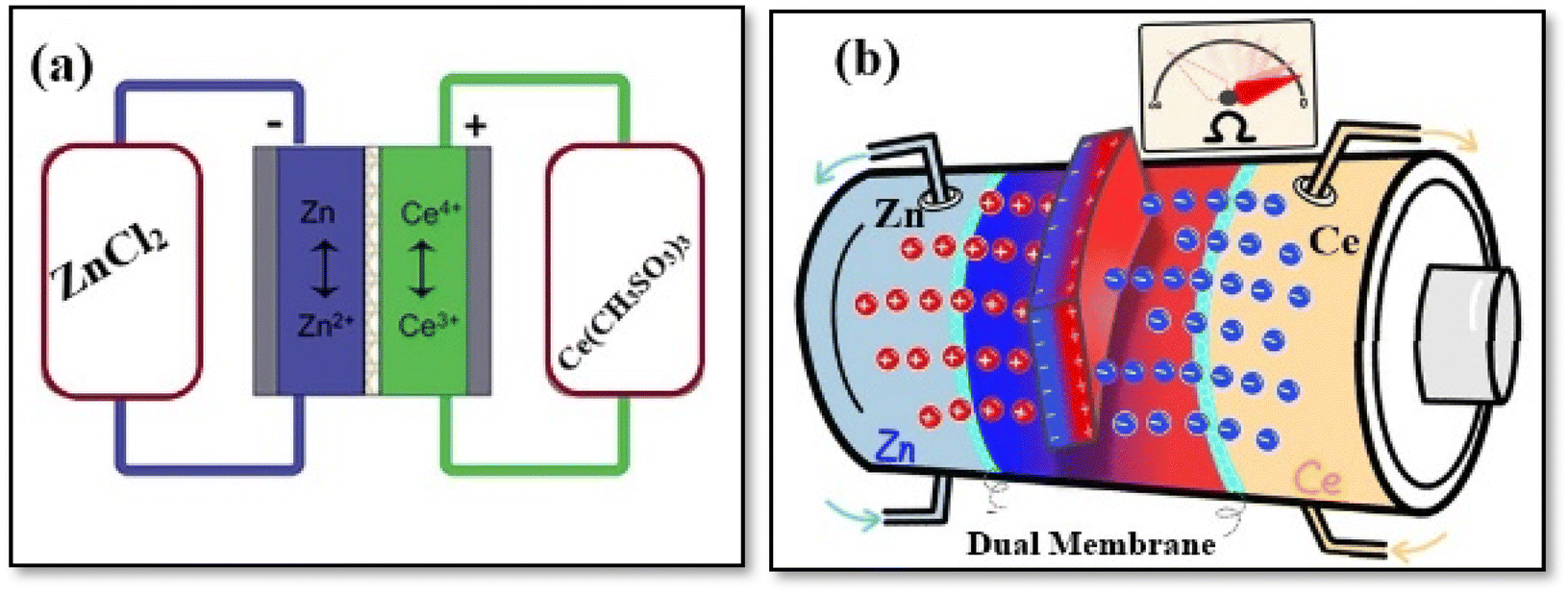 | ||
| Fig. 18 (a) Schematics diagram of Zn–Ce RFB and, (b) dual membrane of Zn–Ce RFBs. Reproduced from ref. 198 with permission from the American Chemical Society, copyright 2022. | ||
5.6. Hybrid zinc–nickel based RFBs
Aqueous zinc–nickel flow battery (FB) chemistry presents several advantages over non-aqueous battery systems, such as lithium-based batteries. Zn–Ni single FBs are an interesting class of ESS. They utilize nickel oxide or nickel hydroxide as the cathode material and zinc as the anode. Both the anolyte and catholyte contain similar compositions, where zinc oxide dissolves in alkaline solutions to form zincate ions.200 The schematic diagram of Zn–Ni FB and performance are shown in Fig. 19a–c. Research by Yuanhui and colleagues suggests that Zn–Ni single FB with high power density show significant promise for large-scale ES applications.201 Their findings indicate that Zn–Ni FBs can function effectively within a temperature range of 0 °C to 40 °C, maintaining an acceptable EE between 53% and 79.1% at a current density of 80 mA cm−2. The study also revealed that in the 0–20 °C range, the temperature sensitivity of CE and EE is 0.65% °C−1 and 0.98% °C−1, respectively. The energy density limitations of Zn–Ni RFBs were addressed in 2019 when Yuanhui introduced a novel approach. This method involved incorporating an additional O2/OH− redox couple alongside NiOOH/Ni(OH)2 as the cathode material, aiming to enhance the overall energy density of the system.202 This approach allows for the complete utilization of electrodeposited Zn during battery discharge, effectively eliminating Zn buildup on the negative electrode during charging. The battery demonstrated sustained performance without degradation for 1100 h, and the positive electrode achieved a specific capacity 2.5 times greater than that of traditional Zn–Ni RFBs. A cost-effective design for a membrane-free alkaline zinc–anode flow-assisted battery underwent testing at two scales. The grid-scale test utilized a 25 kW h system comprising thirty 833 W h cells connected in series, while the bench-scale evaluation employed individual 28 W h cells.203 | ||
| Fig. 19 (a) Schematics diagram of ZNBs. (b) Charge–discharge voltage curves under various temperatures. (c) CE, VE, and EE under various temperatures. Reproduced from ref. 200 and 201 with permission from Elsevier B.V., copyright 2019, and 2014. | ||
5.7. Zinc–air RFBs
The zinc–air battery concept from the 1930s, based on the Leclanché wet battery, is fascinating. It operates using alkaline electrolytes, delivering a voltage range of 1.0 to 1.4 V, which is lower than its theoretical standard potential of 1.62 V. This discrepancy occurs mainly due to internal resistances and kinetic limitations at high current densities, such as 100 mA cm−2. In rechargeable Zn–air batteries, issues like non-uniform zinc electro-deposition and the absence of durable dual-functional catalysts can indeed lead to short cycle life. To address these challenges, a flowable electrolyte system has been employed. This approach helps improve the morphology of zinc deposition, promoting a more uniform layer that minimizes the risk of dendrite growth, which can short-circuit the battery and degrade performance.204Fig. 20a displays a schematic representation of a Zn–air RFB. Jinling and colleagues examined the distinctive properties of three different metal organic frameworks (MOFs).205 They developed two types of composite materials with exceptional characteristics, including high specific surface area, superior conductivity, a rich hierarchical porous structure, and multiple catalytically active components. These materials were specifically designed for use in zinc–air FB. In the Fe/12Zn/Co-NCNT air cathode configuration, the Zn–air FB reaches a VOC of 1.518 V, peak power density of 166 mW cm−2, and specific capacity of 809.1 mA h g−1. In Fig. 20b–d, Fe/12/Co-NCNTs-based catalysts are shown as a typical catalyst for Zn–air RFB batteries.
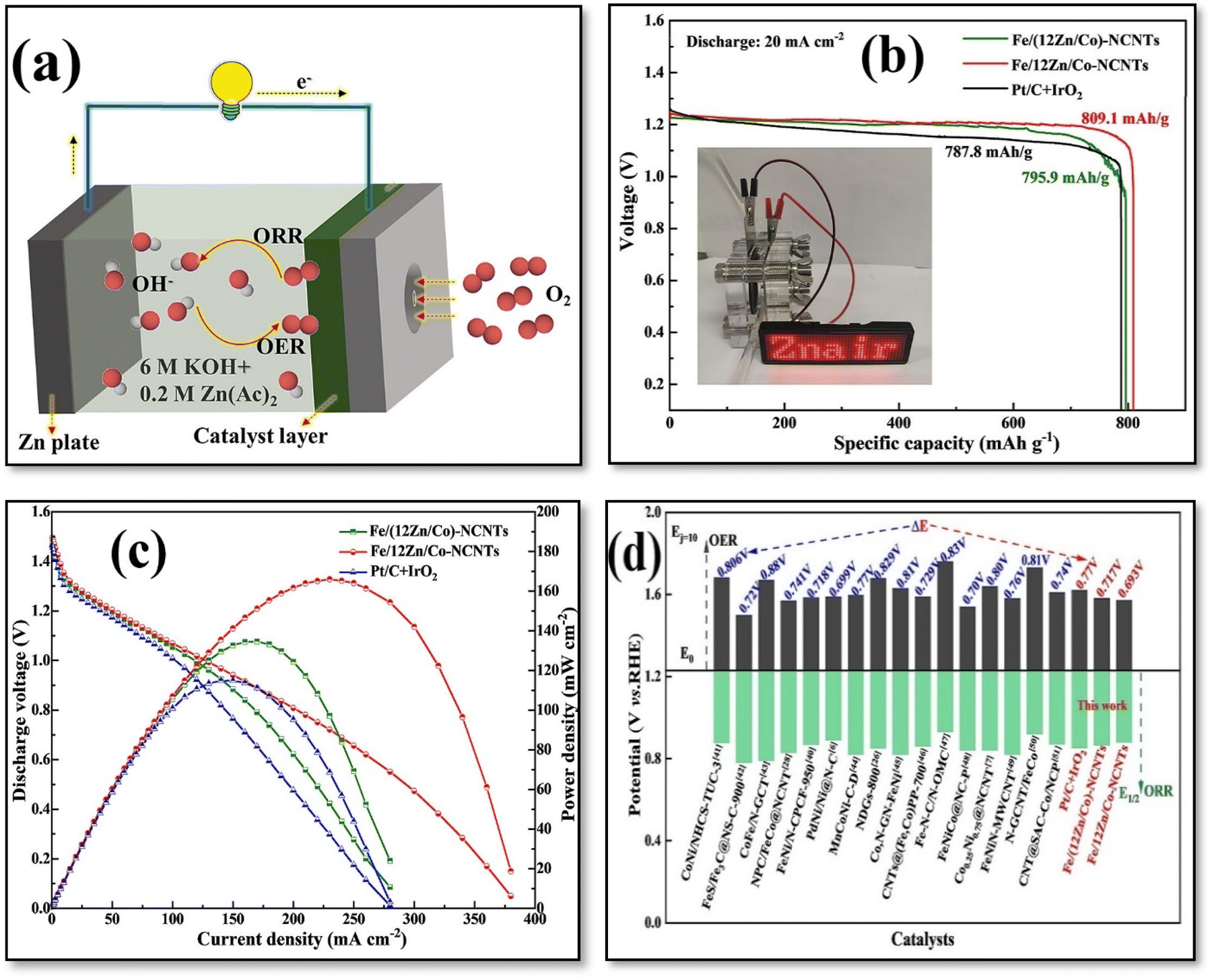 | ||
| Fig. 20 (a) Schematics diagram, (b) discharge curves, (c) discharge voltage and current density and, (d) comparison of ΔE values of Zn–air RFBs. Reproduced from ref. 205 with permission from Elsevier B.V., copyright 2023. | ||
5.8. Soluble lead based RFB
Lead–acid batteries, first demonstrated by Gaston Planté in 1860, remain widely used, particularly in automotive applications. Despite their longevity, a significant disadvantage is their limited energy density utilization, typically only 30–40% of the theoretical capacity.206 Lead–acid batteries, although possessing a seemingly low energy density—ranging from 30 to 40% of the theoretical maximum compared to lithium-ion batteries' 90%—offer several advantages. They are constructed using widely available, cost-effective materials and employ a non-combustible aqueous electrolyte. Furthermore, the manufacturing processes for these batteries boast an impressive 99% recycling rate, significantly reducing their environmental footprint.206 Like any technological advancement, the potential risks associated with this technology can be mitigated through proper material handling, adherence to good manufacturing practices, and dedicated waste management strategies.207,208 The environmental impact of lead is significantly reduced due to the impressive 99% recycling rate of lead–acid batteries and the implementation of strict regulations governing lead emissions into the environment (National Recycling Rate Study 2019). For the lead acid battery, an alternative flow battery approach was demonstrated that utilizes the different oxidation states of Pb (0, +2, +4). Comparatively to other FB, Pb-RFB has undivided cells, not requiring a membrane between the catholyte and anolyte As shown in Fig. 21a and b, the device was able to maintain 500 cycles at 20 mA cm−2 on a square area with an EE of 79%. It was demonstrated that using trimethyloctadecylammonium chloride alongside NaF/LiF as electrolyte additives synergistically improved SLRFB's electrochemical behavior and lifespan. Without additives, the SLRFB's durability is restricted to 45 charge/discharge cycles due to electrode shorting. The CE declined from 93% to 74% by the 46th cycle at a 20 mA cm−2 charging current density. In contrast, with additives, the cell endured over 500 cycles, maintaining average efficiencies of 94% (CE), 78% (VE), and 74% (EE) (Fig. 22).209 Furthermore, conventional SLRFB electrolytes can provide ES of up to 40 W h kg−1, with performance at the 100 cm2 electrode level achieving 90% charge and 80% VE over 100 cycles. Additionally, the SLRFB has been evaluated at a larger scale, utilizing a four-cell stack with 1000 cm2 electrodes.210 | ||
| Fig. 21 (a) Schematics diagram of SLRFB, (b) image of electrodes after 500th cycles, (c) charge, and discharge profile at different cycles and, (d) efficiency plots of Pb-RFBs. Reproduced from ref. 209 with permission from Elsevier B.V., copyright 2022. | ||
 | ||
| Fig. 22 Comparison of area-specific capacity, current density, and cycle life of SLRFB with the reported data. Reproduced from ref. 209 with permission from Elsevier B.V., copyright 2022. | ||
6. Electrode based RFB
Over the past few years, numerous studies have focused on 3D electrode materials for VRFB. A chronological overview of significant advancements in VRFB can be found in Fig. 23. The extensive research on 3D electrode materials is attributed to their adaptable structural design and high specific surface area. Utilizing raw materials with 3D continuous network properties allows for versatility in electrode structure manipulation. Furthermore, these materials allow electrons to be transported in three dimensions while reducing ion diffusion pathways.211 Furthermore, the flow field (FF) is crucial in flow battery operation. It serves multiple purposes: ensuring uniform electrolyte distribution across the surface of 3D electrode materials, facilitating current application and collection, and providing structural support for the electrode material.212,213 The existing state-of-the-art on 3D electrode materials in VRFB lack comprehensiveness and systematic analysis. There is insufficient examination of how various electrode types affect morphology, electrochemical activity, and mass transfer. The objective is to present a comprehensive and up-to-date overview of 3D electrodes, enhancing the understanding of advanced design strategies and identifying future challenges in applying 3D electrode materials.214,215 | ||
| Fig. 23 Timeline of outstanding works in VRFB research. Reproduced from ref. 218 with permission from the American Chemical Society, copyright 2024. | ||
This state-of-the-art study examines the recent advancements in 3D electrode materials for VRFB, as illustrated in Fig. 24. The introduction of 3D electrodes has broadened the range of conventional electrode types, now encompassing foams, biomass-derived materials, and electrospun fibers. The characteristics of these 3D electrodes in VRFB applications are analyzed. The adaptable design of 3D electrodes substantially enhances electrochemical performance and mitigates concentration polarization. The review concludes by discussing the future potential and obstacles facing 3D electrodes in VRFB technology, aiming to offer insights for the considerable growth opportunities in this field.
 | ||
| Fig. 24 Detailed summary diagram of 3D electrodes. Reproduced from ref. 218 with permission from the American Chemical Society, copyright 2024. | ||
6.1. 3D electrodes
Commercial electrodes face limitations due to their rigid structure, absence of active sites, and restricted specific surface area, which hinder ion diffusion pathways. To overcome these challenges, researchers have recently developed 3D electrodes with customizable structures and compositions. These innovative electrodes are derived from various sources, including foam, biomass, and electrospun nanofibers, offering improved performance and versatility.216,217By designing flexible electrodes and functionalizing them compositionally, it is possible to achieve high-speed mass transfer channels and large amounts of active sites for vanadium redox reaction. The electrode modification approach can be classified into three main categories: inherent processing, catalyst incorporation, and electrode derivative development. Enhancing catalytic efficiency is achieved through intrinsic electrode treatment, which includes methods such as etching, functional group modification, and doping with heteroatoms. To mitigate concentration polarization, various catalysts, including metals, metal oxides, and metal-based compounds, have been integrated into the electrode structure.218 Additionally, by conductive matrix additions, functional doping, and group modifications, these electrodes provide a fast ion diffusion path and increase the active site of vanadium redox reactions. 3D electrodes with customizable structures and compositions have been developed, derived from sources such as foam, biomass, and electrospun nanofibers. These materials' inherent porous characteristics are fully exploited to enhance the interaction between the electrolyte and electrode surface, thus creating efficient pathways for mass transport. The unique structure of melamine foam-based porous carbon enhances conductivity and performance in applications like supercapacitors and batteries. In addition to having a distinctive 3D interconnected network, an abundance of defects, excellent chemical stability, and a high specific surface area, melamine foam-based porous carbon materials are promising as 3D electrode materials. The use of N, P codoping in reduced graphene oxide (rGO) can significantly enhance the electrochemical properties of the electrodes as reported by Zhang team.219 The combination with carbonized melamine foam likely contributes to improved conductivity and specific surface area, making it suitable for high-performance energy storage devices as shown in Fig. 25a. Atomic doping and intricate network structure are illustrated in Fig. 25b. The melamine foam electrode benefits from smooth pathways provided by carbonized and loaded rGO, as depicted in Fig. 25c. The electrode's active sites are enhanced through the incorporation of nitrogen and phosphorus atoms. By incorporating nitrogen and phosphorus doping into the carbonized melamine foam and graphene oxide, it likely enhances the electrochemical performance, including increased capacitance and better cycling stability. Such modifications can improve charge transfer kinetics and overall energy storage capacity, making it highly effective for batteries.219 The construction of a W/Zr bimetallic oxide@carbon melamine foam electrode represents a significant advancement in electrode design. By incorporating tungsten (W) sites into the Zr-UiO-66 framework as shown in Fig. 25d. The presence of both WO3 and ZrO2 can facilitate electron transfer during redox reactions, improving the overall electrochemical performance (Fig. 25e). Compared to the original foam, the W/ZrBO@C-1000 electrode demonstrates a 14.74% enhancement in energy EE and exhibits favorable long-term durability across 500 successive charge–discharge cycles.220 The exceptional stability performance can be attributed to the highly organized distribution of the catalyst on the foam's surface and its superior adhesion capabilities. While the melamine foam composite electrode outperforms commercially available electrodes in conductivity, surface area, and catalytic efficiency, it is important to note that this innovative design necessitates additional processing steps.
 | ||
| Fig. 25 (a) NP-CMF-G-1000 electrode (b) Scaffold microscopic catalytic schematic mechanism (c) a schematic diagram of conductivity improvement. Reproduced from ref. 219 with permission from Elsevier B.V., copyright 2022 (d) a schematic diagram of the hydrothermal preparation process of W/Zr-UIO-66. (e) W and Zr promote the catalytic structure diagram. Reproduced from ref. 220 with permission from Elsevier B.V., copyright 2023. | ||
Biomass-based electrodes indeed present a promising avenue for sustainable energy storage solutions. Their environmental friendliness and inherent structural advantages make them attractive candidates for various applications. The vertical arrangement channels in wood-based electrodes can facilitate efficient ion transport, enhancing performance in batteries and supercapacitors. The ability to utilize the natural structure of biomass without extensive modification not only reduces costs but also maintains the ecological benefits associated with renewable materials. This approach aligns well with the growing emphasis on sustainability in energy technology.221 In the carbonized wood-based electrode, the stratified and minimally tortuous channels serve as efficient pathways for the rapid movement of ionically conductive electrolytes and conductive substrates in a FB. Adding drilled holes facilitates the electrolyte's diffusion between the parallel channels (Fig. 21a). A flexible carbon sponge is introduced as a potential alternative electrode for VRFB. This sponge utilizes its interconnected pore structure to facilitate electrolyte flow and ion movement.222 The conductive matrix of the sponge ensures efficient electron transfer (Fig. 26c). The carbon sponge demonstrates stability in cycle tests, completing 200 cycles at a consistent current density without significant efficiency loss. Additionally, natural cotton, when used as a precursor, offers advantages over sponges. It provides an interconnected porous structure and contributes abundant oxygen functional groups. The cotton-derived (CC) electrode developed by Zhang et al.223 highlights the benefits of using natural fibers for electrode materials. The carbonized cotton's porous, entangled structure retains the original 3D framework and enhances ion transport, making it effective for energy storage applications. The presence of oxygen functional groups contributes to improved hydrophilicity, which is crucial for facilitating the electrolyte's wetting of the electrode surface. This can significantly reduce concentration polarization during electrochemical reactions, leading to better overall performance. A monolithic carbon electrode (NO-MC) with nitrogen-rich defects and oxygen functional groups was prepared by Wang et al. through the processes of degumming and carbonization (Fig. 26e).224 Using double cocoons derived from nitrogen-doped monolithic carbon materials is a fascinating development in the realm of advanced electrodes. The high electrochemical activity and reversibility of the NO-MC electrode make it a strong candidate for energy storage applications. The reported 20% increase in EE compared to commercial carbon paper electrodes at a current density of 100 mA cm−2 highlights the potential of these cocoon-derived materials as shown in Fig. 26f. An oxygen-rich surface doped with nitrogen has a significant role in improving performance. The porous braided structure of silk not only maintains the porous structure after pyrolysis, as is the case with cocoons, but also contains more heteroatoms than cocoons. In Fig. 26g, silk protein-derived carbon fiber fabrics (SCF) are used as electrodes of VRFB.225 The distinctive fabric structure of SCFs remains intact even at elevated temperatures exceeding 1600 °C, resulting in a highly porous macrostructure. Furthermore, a single-cell VRFB utilizing a pair of symmetrical SCFs demonstrates an EE of 86.8%. The battery exhibits long-term cycling stability, as evidenced by a capacity retention rate of 91% after 100 galvanostatic charge/discharge cycles. Biomass materials propose diverse chemical compositions and inherent porous structures, offer excellent versatility for creating 3D electrodes. The natural porosity allows for effective ion transport and increased surface area, which are crucial for enhancing electrochemical performance. Additionally, their rich chemical diversity enables tailored modifications, allowing for the optimization of properties like conductivity and stability. This flexibility makes biomass a promising candidate for sustainable and efficient electrode materials in various applications, from energy storage to sensors.
 | ||
| Fig. 26 (a) Schematic principles of the holey 3D-wood electrode for VRFB. Reproduced from ref. 221 with permission from Elsevier B.V., copyright 2020. (b) Schematic illustration of the flexible carbon sponge electrode Reproduced from ref. 222 with permission from John Wiley & Sons Ltd, copyright 2022 (c) cross profile of carbonized fibers reproduced from ref. 223 with permission from Elsevier B.V., copyright 2017 (d) schematic diagram of fabricating NO-MC electrode material (e) schematic diagram of an alternative sustainable energy ecosystem ((d) and (e) reproduced from ref. 224 with permission from Elsevier B.V., copyright 2019) (f) schematic of the fabrication for SCF reproduced from ref. 225 with permission from Elsevier B.V., copyright 2021. | ||
The cell's performance in terms of efficiency is enhanced, and its lifespan is extended. To meet practical application needs, addressing electronic conductivity is crucial to prevent power density reduction. This issue can be resolved through the development of suitable synthesis techniques. By enhancing the electron transfer mechanism, a greater energy storage capacity can be achieved. Typically, slow electron movement results in sluggish electrochemical reaction dynamics, leading to poor cycling stability and rate capabilities. Nevertheless, further investigation is needed to fully understand the charge transfer mechanism of 3D electrocatalysts, which influences the electrochemical performance of VRFB.218
7. An analysis of the levelized price of energy storage
A major obstacle to the deployment of RFB technologies is their economic viability, including the system's capital costs, which must be lowered to penetrate the EES market. Variable studies suggested that combining renewable energy with energy storage systems costing $100 per kW per h would be the most cost-effective method for generating electricity.226–228 Multiple capital cost estimates exist for RFB systems, with figures expressed in dollars per energy capacity for each discharge cycle at rated power output, represented as $ per kW per h per cycle. The Levelized Cost of Energy Storage calculations encompass various factors throughout the system's entire lifespan. These factors include the initial investment, operational expenses, upkeep costs, efficiency decline, and necessary component replacements. This data is essential for investors, government officials, and power companies to make well-informed choices regarding energy storage investments and the incorporation of sustainable energy sources into the electrical grid.229 A straightforward formula for assessing the LCOS of RFBs in various multi-hour applications has been proposed by Robert M. Darling in recent times. The researchers have calculated the Levelized Cost of Storage (LCOS) for various RFBs and lithium-ion batteries across different scenarios. These include use cases 1 (4 hours, 300 cycles per year), 8 (8 hours, 300 cycles per year), 10 (4 hours, 500 cycles per year), and a hypothetical long-duration energy storage (LDES) case 13 (100 hours, 36 cycles per year). For all calculations, they assumed an annual discount rate (r) of 10%, a lifetime (tL) of 20 years, and a power capacity cost (pc) of $25 per MWper h. As shown in Fig. 27 , the results are impressive. VRFB stands out as the most advanced technology among all RFBs, boasting a high round trip efficiency (RTE) of 81%, even when operating at elevated current densities compared to other RFB types. The high RTE is crucial for minimizing the LCOS of VRFB, particularly because vanadium salt comes at a higher cost (124.4 $ per kW per h system).230 Table 7 presents the cost estimates for various grid storage applications. The data in Table 7 reveals that aqueous RFBs have lower capital costs compared to their non-aqueous counterparts. Additionally, the capital cost decreases as the energy-to-power (E/P) ratio increases, which corresponds to smaller power ratings and longer durations. Several RFB technologies that have been commercialized, including VRFB, zinc–bromine (Zn–Br2), and zinc–ferricyanide (Zn–Fe(CN)6), exhibit the lowest capital costs, ranging from $172 to $435 per kilowatt-hour. However, these figures still significantly exceed the Department of Energy's (DoE) target of less than $100 per kilowatt-hour.231 | ||
| Fig. 27 For use cases 1, 4, 8, and 13, LCOS values were determined for Li-ion batteries, eight types of aqueous RFBs, and two theoretical non-aqueous RFBs. Reproduced from ref. 11 with permission from John Wiley & Sons Ltd, copyright 2024. | ||
| Application | RFB | Cell stacks (cost $ per kW per h) | Electrolyte (cost $ per kW per h) | Balance of plant (cost $ per kW per h) | Battery management system | Total cost (cost $ per kW per h) |
|---|---|---|---|---|---|---|
| Solar energy integration, (2 MW, 6 h E/P = 6) | VRFB | 156.14 | 75.22 | 18.99 | 1.51 | 251.86 |
| Zn–Br2 | 246.50 | 159.10 | 27.47 | 2.64 | 435.72 | |
| Zn–Fe(CN)6 | 369.75 | 13.74 | 26.08 | 3.96 | 413.55 | |
| Vi-TEMPO | 327.91 | 121.22 | 65.53 | 3.16 | 517.84 | |
| DHPS-Fe(CN)6 | 100.89 | 46.77 | 19.75 | 0.97 | 168.40 | |
| Demand charge management (10 MW, 11 h E/P = 11) | VRFB | 85.17 | 75.22 | 11.55 | 0.82 | 172.77 |
| Zn–Br2 | 134.45 | 159.10 | 15.34 | 1.44 | 310.34 | |
| Zn–Fe(CN)6 | 201.68 | 13.74 | 17.93 | 2.16 | 235.52 | |
| DHPS-Fe(CN)6 | 55.03 | 46.77 | 12.47 | 0.53 | 114.81 | |
| Li-TEMPO | 430.25 | 410.07 | 19.79 | 4.61 | 864.73 |
8. Conclusion and perspective
RFB are crucial for implementing renewable energy systems. Although vanadium-based electrolytes remain dominant, developing alternative electrolytes is essential to achieve the necessary cost and energy targets for a sustainable energy future. The advancement of VRFB is hindered by challenges such as rigid structures and inadequate electrochemical performance of the electrodes. Furthermore, the toxicity and limited solubility of vanadium-based electrolytes are driving researchers to explore aqueous zinc, iron, or manganese-based batteries for stationary ES. As VCl3 offers another redox chemistry that could prove useful in certain applications, however it is also poor solubility and produces chlorine gas when used in conjunction with HCl. As a result, the researchers overcame the obstacle by mixing acids such as sulfuric and hydrochloric acids together. In addition, VFRBs can be safely operated at temperatures ranging from 10 to 40 °C. A change in temperature can reverse these precipitations and form soluble vanadium solutions. Zinc–iron RFBs can have electrolyte crossover difficulties, but by adding glycine to the catholyte, the battery achieved impressive results. Zinc–iodine RFBs continue to face significant obstacles, particularly regarding the stability of the catholyte and the decrease in capacity over time. However, the addition of ammonium chloride or bromide can interact with iodide ions to create stable iodine chloride or bromide compounds, which enhances the battery's efficiency and performance. ESS decentralization, emergency power backup systems, and energy density pose challenges to widespread practical application of Zn–Br RFBs. SL-RFBs offer cost-effectiveness, but the PbO2 plating, Pb dendrites, and side reactions present challenges. A FB was able to perform 2000 cycles using lead methane sulfonate and methane sulfonic acid at 0.7 m and 1 m, respectively. Although zinc is plentiful and environmentally friendly, the electrochemical reaction involving plating and stripping in this category of batteries restricts its lifespan in various practical applications of aqueous-based systems. The optimal performance of RFB's heavily relies on effective cell design. Research involving both modeling and experimental approaches has examined pump optimization and various flow field patterns, including parallel, serpentine, and interdigitated configurations. These studies indicate that the circuitous flow field pattern is the most suitable for cost-effective operation of large-scale RFB's.Several issues limit the further development of VRFB, including fixed structures and low electrochemical activity. Three-dimensional electrodes exhibit several advantageous properties, including excellent conductivity, customizable design, high specific surface area, porosity, and numerous active sites. These characteristics make them an effective approach for enhancing catalytic performance. This analysis examines various types of 3D electrodes utilized in VRFB. By manipulating the structure of foam and biomass, the 3D electrode configuration can be modified to improve both charge transfer and ion diffusion processes. 3D electrocatalysts featuring conductive networks with multiple active sites are achieved through the use of composite materials, including those based on metals and carbon. These materials are enhanced by modifying them with functional heteroatoms and leveraging strong synergistic effects. Despite the significant potential of 3D structured electrodes in VRFB, researchers must continue to address and overcome various challenges for their successful commercial implementation (Fig. 28).
 | ||
| Fig. 28 Advantages and challenges of 3D electrode. Reproduced from ref. 218 with permission from the American Chemical Society, copyright 2024. | ||
The selection and development of 3D electrodes must prioritize several key points. To maintain its performance over time, the electrode must preserve its three-dimensional structure during repeated cycling, withstanding physical deterioration. The material should possess good electrical conductivity to enable efficient charge transfer, which can be improved through techniques like doping or adjusting its composition. Maximizing ion accessibility and enhancing electrochemical reactions require a high surface area and optimal porosity, resulting in improved capacity and rate performance. To ensure long-term functionality and safety, the materials should be able to resist chemical degradation in the operating environment. The electrode material must be compatible with the device's electrolytes and other components to prevent unwanted reactions. Using biomass or renewable materials for the electrode aligns with sustainability objectives, making it more environmentally friendly. By addressing these requirements, the development of 3D electrodes can lead to significant advancements in performance for applications like batteries, supercapacitors, and sensors.
9. The RFB in Egypt
According to the Scopus database for the last five years (2020–2024), Fig. 29 shows articles on “RFBs”. As seen in Fig. 29, China and the United States both contributed greatly to this field. Egypt researchers have published twenty-five articles in this filed. For the first time, El Sawy et al.232 demonstrated the exceptional electrocatalytic performance of fullerene C76 for VO2+/VO2+ in all-VRFB. Their study revealed a significant reduction in charge transfer resistance, with a 99.5% decrease compared to treated carbon cloth and a 97% decrease compared to untreated carbon cloth. Furthermore, the research showed inhibition of chlorine evolution and maintained stability after 100 cycles. Novel free-standing electrospun nanofibrous carbon-loaded composites with textile-like properties have been produced and used as effective electrodes for VRFBs, as El-Nagar et al.233 demonstrated. Electrospun nanofibers made of polyacrylonitrile and loaded with various forms of carbon black (CB) were produced, resulting in a strong, independent network. Fibers with a rough surface and a greater mean diameter were produced by the 14% incorporation of CBs. Compared to commercial carbon felt (0.6 m2 g−1), it offered increased BET surface area of 83.8 m2 g−1 for as-spun fibers and 356.7 m2 g−1 for carbonized fibers. It was discovered that the reaction of V(II)/V(III) on carbon cloth electrodes modified with tungsten oxide nanoflakes, nanowires, and nanospheres applied to negative half-cell reactions of the process. As a result of its improved reaction kinetics, the tungsten oxide nanoflake (WNFs) structure has the highest charge/discharge capacity and EE at a relatively high current density of 60 mA cm−2.233 | ||
| Fig. 29 RFB publications during the last 5 years in the Scopus database. | ||
Abbreviations
| ES | Energy storage |
| EST | Energy storage technologies |
| EB | Redox flow battery |
| ES | Flow battery |
| GHG | Greenhouse gas |
| PHES | Pumped hydro energy storage |
| CAES | Compressed air energy storage |
| TES | Thermal energy storage |
| FES | Flywheel Energy Storage |
| SMES | Superconducting Magnetic Energy Storage |
| EDLC | Electric Double Layer Capacitor |
| ECES | Electrochemical Energy Storage |
| 3D | Three-dimensional |
| VRFB | Vanadium redox flow battery |
| VOC | Open circuit voltage |
| CB | Carbon black |
| EE | Energy efficiency |
| SOC | State of charge |
| RAS | Redox-active species |
| CE | Coulombic efficiency |
| VE | Voltage efficiency |
| PCS | Power Conditioning System |
| VSI | Voltage Source Inverter |
| CSI | Current Source Inverter |
| DOD | Depth of discharge |
| SC | Supercapacitor |
| LCA | Life cycle assessment |
| LCOS | Levelized cost of storage |
| PTFE | Polytetrafluoroethylene |
| PCS | Power conditioning system |
| EPPD | Ethylene-polypropylene-diene |
| PVC | Polyvinyl chloride |
| PVDF | Polyvinylidene fluoride |
| SCF | Silk carbon fiber |
| MSA | Methane sulfonic acid |
| CV | Cyclic voltammetry |
| MOFs | Metal organic frameworks |
| NO-MC | Monolithic carbon electrode |
| WNFs | Tungsten oxide nanoflake |
| DC | Direct current |
Data availability
No primary research results, software, or code have been included and no new data were generated or analysed as part of this review.Conflicts of interest
The authors confirmed that this article has no conflict of interest.Acknowledgements
It is my pleasure to thank the Scientific Promotions Committee for Chemistry and Science of Materials Technology for its suggestions. The author is grateful for STDF's supporting fund number (46944) provided by the Science, Technology & Innovation Funding Authority.References
- O. Adesina, I. A. Anzai, J. L. Avalos and B. Barstow, Chem, 2017, 2, 20–51 Search PubMed.
- D. Lips, J. Schuurmans, F. B. Dos Santos and K. Hellingwerf, Energy Environ. Sci., 2018, 11, 10–22 Search PubMed.
- P. Zhang, B. Y. Guan, L. Yu and X. W. D. Lou, Chem, 2018, 4, 162–173 CAS.
- Z. Yang, J. Zhang, M. C. Kintner-Meyer, X. Lu, D. Choi, J. P. Lemmon and J. Liu, Chem. Rev., 2011, 111, 3577–3613 CrossRef CAS PubMed.
- T. M. Gür, Energy Environ. Sci., 2018, 11, 2696–2767 Search PubMed.
- Y. Ding, C. Zhang, L. Zhang, Y. Zhou and G. Yu, Chem, 2019, 5, 1964–1987 Search PubMed.
- C. Xie, H. Zhang, W. Xu, W. Wang and X. Li, Angew. Chem., 2018, 130, 11341–11346 CrossRef.
- X. Zeng, C. Zhan, J. Lu and K. Amine, Chem, 2018, 4, 690–704 Search PubMed.
- M. R. Lukatskaya, J. I. Feldblyum, D. G. Mackanic, F. Lissel, D. L. Michels, Y. Cui and Z. Bao, Energy Environ. Sci., 2018, 11, 2876–2883 Search PubMed.
- G. L. Soloveichik, Chem. Rev., 2015, 115, 11533–11558 Search PubMed.
- M. Shoaib, P. Vallayil, N. Jaiswal, P. Iyapazham Vaigunda Suba, S. Sankararaman, K. Ramanujam and V. Thangadurai, Adv. Energy Mater., 2024, 2400721 Search PubMed.
- Y. Guo, J. Huang and J.-K. Feng, J. Ind. Eng. Chem., 2023, 118, 33–43 Search PubMed.
- J. Ye, X. Zhao, Y. Ma, J. Su, C. Xiang, K. Zhao, M. Ding, C. Jia and L. Sun, Adv. Energy Mater., 2020, 10, 1904041 CrossRef CAS.
- J. Winsberg, T. Hagemann, T. Janoschka, M. D. Hager and U. S. Schubert, Angew. Chem., Int. Ed., 2017, 56, 686–711 CrossRef CAS PubMed.
- T. Liu, X. Wei, Z. Nie, V. Sprenkle and W. Wang, Adv. Energy Mater., 2016, 6, 1501449 Search PubMed.
- M. Skyllas-Kazacos, M. Chakrabarti, S. Hajimolana, F. Mjalli and M. Saleem, J. Electrochem. Soc., 2011, 158, R55 Search PubMed.
- F. Rahman and M. Skyllas-Kazacos, J. Power Sources, 2017, 340, 139–149 Search PubMed.
- W. M. Carvalho Jr, L. Cassayre, D. Quaranta, F. Chauvet, R. El-Hage, T. Tzedakis and B. Biscans, J. Energy Chem., 2021, 61, 436–445 Search PubMed.
- T. Janoschka, S. Morgenstern, H. Hiller, C. Friebe, K. Wolkersdörfer, B. Häupler, M. Hager and U. Schubert, Polym. Chem., 2015, 6, 7801–7811 Search PubMed.
- T. Janoschka, N. Martin, U. Martin, C. Friebe, S. Morgenstern, H. Hiller, M. D. Hager and U. S. Schubert, Nature, 2015, 527, 78–81 Search PubMed.
- C. Noh, D. Serhiichuk, N. Malikah, Y. Kwon and D. Henkensmeier, Chem. Eng. J., 2021, 407, 126574 Search PubMed.
- J. Heo, J.-Y. Han, S. Kim, S. Yuk, C. Choi, R. Kim, J.-H. Lee, A. Klassen, S.-K. Ryi and H.-T. Kim, Nat. Commun., 2019, 10, 4412 Search PubMed.
- L. Wei, L. Zeng, M. Wu, X. Fan and T. Zhao, Appl. Energy, 2019, 251, 113344 CrossRef CAS.
- Vanadium redox flow battery storage System 2 MW8MWh, https://www.sinjienergy.com/Vanadium-redox-flow-battery-storage-System-2MW8MWh-pd581468668.html Search PubMed.
- M. Yue, Q. Zheng, F. Xing, H. Zhang, X. Li and X. Ma, AIChE J., 2018, 64, 782–795 Search PubMed.
- Q. Zheng, F. Xing, X. Li, T. Liu, Q. Lai, G. Ning and H. Zhang, J. Power Sources, 2015, 277, 104–109 Search PubMed.
- L. Kortekaas, S. Fricke, A. Korshunov, I. Cekic-Laskovic, M. Winter and M. Grünebaum, Batteries, 2022, 9, 4 Search PubMed.
- Y. Lyu, J. Xie, D. Wang and J. Wang, J. Mater. Sci., 2020, 55, 7184–7207 Search PubMed.
- Y. Wang, D. F. R. Diaz, K. S. Chen, Z. Wang and X. C. Adroher, Mater. Today, 2020, 32, 178–203 CAS.
- P. Alotto, M. Guarnieri and F. Moro, Renewable Sustainable Energy Rev., 2014, 29, 325–335 CAS.
- K. J. Kim, M.-S. Park, Y.-J. Kim, J. H. Kim, S. X. Dou and M. Skyllas-Kazacos, J. Mater. Chem. A, 2015, 3, 16913–16933 CAS.
- P. Leung, X. Li, C. P. De León, L. Berlouis, C. J. Low and F. C. Walsh, RSC Adv., 2012, 2, 10125–10156 CAS.
- R. Chen, Chem.–Asian J., 2023, 18, e202201024 CrossRef CAS.
- W. Wang, W. Xu, L. Cosimbescu, D. Choi, L. Li and Z. Yang, Chem. Commun., 2012, 48, 6669–6671 RSC.
- I. Iwakiri, T. Antunes, H. Almeida, J. P. Sousa, R. B. Figueira and A. Mendes, Energies, 2021, 14, 5643 CrossRef CAS.
- P. Ralon, M. Taylor, A. Ilas, H. Diaz-Bone and K. Kairies, Electricity storage and renewables: Costs and markets to 2030, International Renewable Energy Agency, Abu Dhabi, United Arab Emirates, 2017, p. 164.
- E. Sánchez-Díez, E. Ventosa, M. Guarnieri, A. Trovò, C. Flox, R. Marcilla, F. Soavi, P. Mazur, E. Aranzabe and R. Ferret, J. Power Sources, 2021, 481, 228804 CrossRef.
- X. Wang and J. Chai, Nano Mater. Sci., 2021, 3, 17–24 CrossRef CAS.
- S. Eckroad and I. Gyuk, Electric Power Research Institute Report, 20021007189 Search PubMed.
- L. H. Thaller, Electrically rechargeable redox flow cells, in: Intersociety Energy Conversion Engineering Conference, 9th, Proceedings, American Society of Mechanical Engineers, San Francisco, Calif., New York, 1974, p. 924–928, August 26-30, (A75-10476 01-44) Search PubMed.
- F. Y. Fan, W. H. Woodford, Z. Li, N. Baram, K. C. Smith, A. Helal, G. H. McKinley, W. C. Carter and Y.-M. Chiang, Nano Lett., 2014, 14, 2210–2218 CrossRef CAS.
- J. Chacón and P. R. Soler, Electrically rechargeable Aluminum-air batteries to power Smart Cities, 2013 International Conference on New Concepts in Smart Cities: Fostering Public and Private Alliances (SmartMILE), IEEE Xplore, 2013 Search PubMed.
- F. Cheng and J. Chen, Chem. Soc. Rev., 2012, 41, 2172–2192 CAS.
- M. A. Rahman, X. Wang and C. Wen, J. Electrochem. Soc., 2013, 160, A1759 CAS.
- A. Balakrishnan and K. Subramanian, Nanostructured Ceramic Oxides for Supercapacitor Applications, CRC Press, Boca Raton, 2014 Search PubMed.
- J.-Y. Chen, C.-L. Hsieh, N.-Y. Hsu, Y.-S. Chou and Y.-S. Chen, Energies, 2014, 7, 5863–5873 Search PubMed.
- K. Bromberger, J. Kaunert and T. Smolinka, Energy Technol., 2014, 2, 64–76 CAS.
- Y. Yang, Y. Zhang, L. Tang, T. Liu, S. Peng and X. Yang, J. Power Sources, 2020, 450, 227675 CAS.
- H. Zhao, Q. Wu, S. Hu, H. Xu and C. N. Rasmussen, Appl. Energy, 2015, 137, 545–553 CrossRef.
- M. M. Rahman, A. O. Oni, E. Gemechu and A. Kumar, Energy Convers. Manage., 2020, 223, 113295 CrossRef CAS.
- F. Barnes and J. Levine, Large energy storage systems, Taylor & Francis Group, NY, 2011 Search PubMed.
- M. Aneke and M. Wang, Appl. Energy, 2016, 179, 350–377 CrossRef.
- A. Blakers, M. Stocks, B. Lu and C. Cheng, Prog. Energy, 2021, 3, 022003 CrossRef.
- D. Manolakos, G. Papadakis, D. Papantonis and S. Kyritsis, Energy, 2004, 29, 57–69 CAS.
- A. Chatzivasileiadi, E. Ampatzi and I. Knight, Renewable Sustainable Energy Rev., 2013, 25, 814–830 CrossRef CAS.
- G. Locatelli, D. C. Invernizzi and M. Mancini, Energy, 2016, 104, 114–131 Search PubMed.
- M. S. Javed, T. Ma, J. Jurasz and M. Y. Amin, Renewable Energy, 2020, 148, 176–192 CrossRef.
- S. Rehman, M. M. Alam, J. P. Meyer and L. M. Al-Hadhrami, Renewable energy, 2012, 38, 258–268 Search PubMed.
- T. Ma and M. S. Javed, Energy Convers. Manage., 2019, 182, 178–190 CrossRef.
- C. Bullough, C. Gatzen, C. Jakiel, M. Koller, A. Nowi and S. Zunft, Advanced adiabatic compressed air energy storage for the integration of wind, European Wind Energy Conf. EWEC 2004, London UK, 2004, Item URL in elib:https://elib.dlr.de/2960/ Search PubMed.
- M. Martinez, M. G. Molina, F. Frack and P. E. Mercado, IEEE Latin America Transactions, 2013, 11, 466–472 Search PubMed.
- E. Jannelli, M. Minutillo, A. L. Lavadera and G. Falcucci, Energy, 2014, 78, 313–322 Search PubMed.
- R. Madlener and J. Latz, Appl. Energy, 2009, 101, 299–309 Search PubMed.
- F. Nadeem, S. S. Hussain, P. K. Tiwari, A. K. Goswami and T. S. Ustun, IEEE access, 2018, 7, 4555–4585 Search PubMed.
- J. Kim, Y. Suharto and T. U. Daim, J. Energy Storage, 2017, 11, 25–54 Search PubMed.
- A. Evans, V. Strezov and T. J. Evans, Renewable Sustainable Energy Rev., 2012, 16, 4141–4147 Search PubMed.
- P. Denholm and G. L. Kulcinski, Energy Convers. Manage., 2004, 45, 2153–2172 CrossRef CAS.
- M. M. Rahman, A. O. Oni, E. Gemechu and A. Kumar, Environmental Assessment of Renewable Energy Conversion Technologies, 2022, pp. 249–276 Search PubMed.
- E. A. Bouman, M. M. Øberg and E. G. Hertwich, Energy, 2016, 95, 91–98 CrossRef CAS.
- E. Oró, A. Gil, A. De Gracia, D. Boer and L. F. Cabeza, Renewable Energy, 2012, 44, 166–173 CrossRef.
- S. Shivashankar, S. Mekhilef, H. Mokhlis and M. Karimi, Renewable Sustainable Energy Rev., 2016, 59, 1170–1184 CrossRef.
- H. Chen, T. N. Cong, W. Yang, C. Tan, Y. Li and Y. Ding, Prog. Nat. Sci., 2009, 19, 291–312 CrossRef CAS.
- G. R. Dheep and A. Sreekumar, Energy Convers. Manage., 2014, 83, 133–148 Search PubMed.
- E. E. John, W. M. Hale and R. P. Selvam, Development of a high-performance concrete to store thermal energy for concentrating solar power plants, ASME 2011 5th International Conference on Energy Sustainability, The american society of mechanical engineers (ASME), 2011, vol. 54686, pp. 523–529, DOI:10.1115/ES2011-54177.
- D. Laing, W.-D. Steinmann, R. Tamme and C. Richter, Sol. Energy, 2006, 80, 1283–1289 CrossRef CAS.
- R. Gabbrielli and C. Zamparelli, J. Sol. Energy Eng., 2009, 131 Search PubMed.
- R. Bayón, E. Rojas, L. Valenzuela, E. Zarza and J. León, Appl. Therm. Eng., 2010, 30, 2643–2651 CrossRef.
- L. Miró, E. Oró, D. Boer and L. F. Cabeza, Appl. Energy, 2015, 137, 793–799 CrossRef.
- S. Koohi-Fayegh and M. A. Rosen, J. Energy Storage, 2020, 27, 101047 CrossRef.
- F. Faraji, A. Majazi and K. Al-Haddad, Renewable Sustainable Energy Rev., 2017, 67, 477–490 CrossRef.
- M. E. Amiryar and K. R. Pullen, Appl. Sci., 2017, 7, 286 CrossRef.
- S. Bankston and C. Mo, Energy Res. J., 2015, 6, 54 CrossRef.
- M. M. Rahman, E. Gemechu, A. O. Oni and A. Kumar, e-Prime – Advances in Electrical Engineering, Electronics and Energy, 2021, 1, 100020 CrossRef.
- S. Schlömer, T. Bruckner, L. Fulton, E. Hertwich, A. McKinnon, D. Perczyk, J. Roy, R. Schaeffer, R. Sims and P. Smith, in Climate Change 2014: Mitigation of Climate Change: Contribution of Working Group III to the Fifth Assessment Report of the Intergovernmental Panel on Climate Change, Cambridge University Press, 2014, pp. 1329–1356 Search PubMed.
- Z. Zhong, J. Fang, K. Hu, D. Huang, X. Ai, X. Yang, J. Wen, Y. Pan and S. Cheng, CSEE Journal of Power and Energy Systems, 2023, 9, 1266–1283 Search PubMed.
- A. Anand, A. S. Gour, T. S. Datta and V. V. Rao, Low-Temperature Technologies and Applications, 2025, DOI:10.5772/intechopen.1008780.
- P. Mukherjee and V. V. Rao, Phys. C, 2019, 563, 67–73 CrossRef CAS.
- N. S. Ghiasi and S. M. S. Ghiasi, Energy Storage Applications in Power Systems, 2023 Search PubMed.
- J. D. Rogers, R. I. Schermer, B. L. Miller and J. F. Hauer, Proc. IEEE, 1983, 71, 1099–1107 Search PubMed.
- T. Mito, A. Kawagoe, H. Chikaraishi, R. Maekawa, T. Hemmi, K. Okumura, R. Abe, T. Baba, H. Ogawa and M. Yokota, IEEE Trans. Appl. Supercond., 2007, 17, 1973–1976 Search PubMed.
- K. Shikimachi, N. Hirano, S. Nagaya, H. Kawashima, K. Higashikawa and T. Nakamura, IEEE Trans. Appl. Supercond., 2009, 19, 2012–2018 Search PubMed.
- Q. Wang, Y. Dai, S. Song, H. Wen, Y. Bai, L. Yan and K. Kim, IEEE Trans. Appl. Supercond., 2008, 18, 754–757 Search PubMed.
- L. Xiao, Z. Wang, S. Dai, J. Zhang, D. Zhang, Z. Gao, N. Song, F. Zhang, X. Xu and L. Lin, IEEE Trans. Appl. Supercond., 2008, 18, 770–773 Search PubMed.
- H. Kim, K. Seong, J. Cho, J. Bae, K. Sim, S. Kim, E. Lee, K. Ryu and S. Kim, IEEE Trans. Appl. Supercond., 2006, 16, 574–577 Search PubMed.
- H. Yeom, S. Park, Y. Hong, D. Koh, K. Seong, H. Kim and T. Seo, IEEE Trans. Appl. Supercond., 2008, 18, 741–744 Search PubMed.
- A. Kalafala, J. Bascunan, D. Bell, L. Blecher, F. Murray, M. Parizh, M. Sampson and R. Wilcox, IEEE Trans. Magn., 2002, 32, 2276–2279 Search PubMed.
- L. M. Uhlaner, M. M. Berent-Braun, R. J. Jeurissen and G. de Wit, J. Bus. Ethics., 2012, 109, 411–429 Search PubMed.
- D. L. Gadenne, J. Kennedy and C. McKeiver, J. Bus. Ethics., 2009, 84, 45–63 Search PubMed.
- B. Hoogendoorn, D. Guerra and P. Van Der Zwan, Small Bus. Econ., 2015, 44, 759–781 CrossRef.
- X. Luo, J. Wang, M. Dooner and J. Clarke, Appl. Energy, 2015, 137, 511–536 CrossRef.
- D. Bhatnagar and V. Loose, A Study for the DOE Energy Storage Systems Program, Sandia National Laboratories, 2012 Search PubMed.
- S. Ruester, J. Vasconcelos, X. HE, E. Chong and J.-M. Glachant, Electricity storage: how to facilitate its deployment and operation in the EU, 2012, Florence School of Regulation2012/05[THINK]Policy BriefsEnergyElectricity Search PubMed.
- M. Sk, P. Pradhan, B. Patra and A. Guria, Mater. Today Chem., 2023, 30, 101582 CrossRef CAS.
- K. Detka and K. Górecki, Energies, 2023, 16, 5034 CrossRef CAS.
- M. Shi, J. Hu, H. Han and X. Yuan, Design of Battery Energy Storage System based on Ragone Curve, 2020 4th International Conference on HVDC (HVDC), IEEE, 2020 Search PubMed.
- J. A. Dowling, K. Z. Rinaldi, T. H. Ruggles, S. J. Davis, M. Yuan, F. Tong, N. S. Lewis and K. Caldeira, Joule, 2020, 4, 1907–1928 CrossRef.
- M. Uhrig, S. Koenig, M. R. Suriyah and T. Leibfried, Energy Procedia, 2016, 99, 35–43 CrossRef CAS.
- R. Ye, D. Henkensmeier, S. J. Yoon, Z. Huang, D. K. Kim, Z. Chang, S. Kim and R. Chen, J. Electrochem. Energy Convers. Storage, 2018, 15, 010801 CrossRef.
- M. Guarnieri, P. Mattavelli, G. Petrone and G. Spagnuolo, IEEE Ind. Electron. Mag., 2016, 10, 20–31 Search PubMed.
- L. Wang, S. Li, D. Li, Q. Xiao and W. Jing, RSC Adv., 2020, 10, 17235–17246 RSC.
- W. Jack, AIChE J., 1996, 42(4), 1195–1197 Search PubMed.
- Á. Frías-Ferrer, J. González-García, V. Sáez, C. P. de León and F. C. Walsh, AIChE J., 2008, 54, 811–823 CrossRef.
- A. Frías-Ferrer, J. González-García, V. Sáez, E. Expósito, C. M. S. ánchez-Sánchez, V. Montiel, A. Aldaz and F. C. Walsh, J. Chem. Educ., 2005, 82, 1395 CrossRef.
- F. Pan and Q. Wang, Molecules, 2015, 20, 20499–20517 CrossRef CAS.
- Y. Ding, C. Zhang, L. Zhang, Y. Zhou and G. Yu, Chem. Soc. Rev., 2018, 47, 69–103 RSC.
- Z. Yuan, Y. Duan, H. Zhang, X. Li, H. Zhang and I. Vankelecom, Energy Environ. Sci., 2016, 9, 441–447 RSC.
- C. A. Machado, G. O. Brown, R. Yang, T. E. Hopkins, J. G. Pribyl and T. H. Epps III, ACS Energy Lett., 2020, 6, 158–176 CrossRef.
- Z. Yuan, Y. Yin, C. Xie, H. Zhang, Y. Yao and X. Li, Adv. Mater., 2019, 31, 1902025 CAS.
- L. Wang, A. T. Pingitore, W. Xie, Z. Yang, M. L. Perry and B. C. Benicewicz, J. Electrochem. Soc., 2019, 166, A1449 CAS.
- J. Dai, Y. Dong, C. Yu, Y. Liu and X. Teng, J. Membr. Sci., 2018, 554, 324–330 CrossRef CAS.
- R. Kim, S. Yuk, J.-H. Lee, C. Choi, S. Kim, J. Heo and H.-T. Kim, J. Membr. Sci., 2018, 564, 852–858 CrossRef CAS.
- C.-Y. Sun, H. Zhang, X.-D. Luo and N. Chen, Ionics, 2019, 25, 4219–4229 CrossRef CAS.
- S. Jiang, S. Lu, Y. Xiang and S. P. Jiang, Adv. Sustainable Syst., 2019, 3, 1900020 CrossRef CAS.
- Q. Dai, Z. Liu, L. Huang, C. Wang, Y. Zhao, Q. Fu, A. Zheng, H. Zhang and X. Li, Nat. Commun., 2020, 11, 13 CrossRef CAS PubMed.
- Y. Xing, L. Liu, C. Wang and N. Li, J. Mater. Chem. A, 2018, 6, 22778–22789 RSC.
- X. Z. Yuan, C. Song, A. Platt, N. Zhao, H. Wang, H. Li, K. Fatih and D. Jang, Int. J. Energy Res., 2019, 43, 6599–6638 Search PubMed.
- S. C. DeCaluwe, A. M. Baker, P. Bhargava, J. E. Fischer and J. A. Dura, Nano energy, 2018, 46, 91–100 CrossRef CAS.
- Z. Yuan, H. Zhang and X. Li, Chem. Commun., 2018, 54, 7570–7588 RSC.
- M. Skyllas-Kazacos, L. Cao, M. Kazacos, N. Kausar and A. Mousa, ChemSusChem, 2016, 9, 1521–1543 CrossRef CAS PubMed.
- P. Alotto, M. Guarnieri, F. Moro and A. Stella, Redox Flow Batteries for large scale energy storage, 2012 IEEE International Energy Conference and Exhibition (ENERGYCON), 2012, DOI:10.1109/EnergyCon.2012.6347770.
- P. Liu, Y. l. Cao, G. R. Li, X. P. Gao, X. P. Ai and H. X. Yang, ChemSusChem, 2013, 6, 802–806 CrossRef CAS PubMed.
- R. Liu, G. Xu, Q. Li, S. Zheng, G. Zheng, Z. Gong, Y. Li, E. Kruskop, R. Fu and Z. Chen, ACS Appl. Mater. Interfaces, 2017, 9, 43632–43639 CrossRef CAS PubMed.
- M. Zhang, M. Moore, J. Watson, T. A. Zawodzinski and R. M. Counce, J. Electrochem. Soc., 2012, 159, A1183 CrossRef CAS.
- M. J. Watt-Smith, P. Ridley, R. Wills, A. A. Shah and F. Walsh, J. Chem. Technol. Biotechnol., 2013, 88, 126–138 CrossRef CAS.
- E. Sum and M. Skyllas-Kazacos, J. Power Sources, 1985, 15, 179–190 CAS.
- B. Sun and M. Skyllas-Kazacos, Electrochim. Acta, 1992, 37, 1253–1260 CAS.
- T. Puleston, A. Clemente, R. Costa-Castelló and M. Serra, Batteries, 2022, 8, 121 CAS.
- A. Mitra, A. Gilankar, S. Das, S. Jena, D. Das, S. B. Majumder and S. Das, J. Mater. Chem. A, 2022, 10, 11636–11650 RSC.
- S. Xiao, L. Yu, L. Wu, L. Liu, X. Qiu and J. Xi, Electrochim. Acta, 2016, 187, 525–534 CrossRef CAS.
- S. Suarez, M. Sahin, Y. Adam, L. Moussignac, D. Cuffari and D. Paterno, J. Power Sources, 2015, 276, 153–161 CrossRef CAS.
- A. Mousa and M. Skyllas-Kazacos, Electrochemically Enabled Sustainability, CRC Press, Boca Raton, FL, USA, 2014, 395–428 Search PubMed.
- M. Skyllas-Kazacos and J. McCann, in Advances in Batteries for Medium and Large-Scale Energy Storage, Elsevier, 2015, pp. 329–386 Search PubMed.
- A. Parasuraman, T. M. Lim, C. Menictas and M. Skyllas-Kazacos, Electrochim. Acta, 2013, 101, 27–40 CrossRef CAS.
- Y. Yang, Y. Zhang, L. Tang, T. Liu, J. Huang, S. Peng and X. Yang, J. Power Sources, 2019, 434, 226719 CrossRef CAS.
- K. E. Rodby, M. L. Perry and F. R. Brushett, J. Power Sources, 2021, 506, 230085 CrossRef CAS.
- C. T.-C. Wan, D. López Barreiro, A. Forner-Cuenca, J.-W. Barotta, M. J. Hawker, G. Han, H.-C. Loh, A. Masic, D. L. Kaplan and Y.-M. Chiang, ACS Sustain. Chem. Eng., 2020, 8, 9472–9482 CrossRef CAS.
- S. Fu, C. Zhu, J. Song, M. H. Engelhard, D. Du and Y. Lin, Electroanalysis, 2017, 29, 1469–1473 CAS.
- N. Blume, O. Zielinski, M. Becker and C. Minke, Energy Technol., 2024, 12, 2300750 CrossRef CAS.
- H. Sun, H. Takahashi, N. Nishiumi, Y. Kamada, K. Sato, K. Nedu, Y. Matsushima, A. Khosla, M. Kawakami and H. Furukawa, J. Electrochem. Soc., 2019, 166, B3125 Search PubMed.
- Y. Lei, S.-q. Liu, C. Gao, X.-x. Liang, Z.-x. He, Y.-h. Deng and Z. He, J. Electrochem. Soc., 2013, 160, A722 CAS.
- Z. Jiang, K. Klyukin, K. Miller and V. Alexandrov, J. Phys. Chem. B, 2019, 123, 3976–3983 CAS.
- C. Sun, J. Chen, H. Zhang, X. Han and Q. Luo, J. Power Sources, 2010, 195, 890–897 CrossRef CAS.
- S. Maurya, S.-H. Shin, Y. Kim and S.-H. Moon, RSC Adv., 2015, 5, 37206–37230 RSC.
- M. Gencten, H. Gursu and Y. Sahin, Int. J. Hydrogen Energy, 2017, 42, 25608–25618 CrossRef CAS.
- M. Gencten, H. Gursu and Y. Sahin, Int. J. Hydrogen Energy, 2017, 42, 25598–25607 CrossRef CAS.
- T. D. Nguyen, L. P. Wang, A. Whitehead, N. Wai, G. G. Scherer and Z. J. Xu, J. Power Sources, 2018, 402, 75–81 CrossRef CAS.
- Z. Li, Y. Lin, L. Wan and B. Wang, Electrochim. Acta, 2019, 309, 148–156 CAS.
- N. Wang, W. Zhou and F. Zhang, Ionics, 2019, 25, 221–229 CAS.
- Y. Wen, Y. Xu, J. Cheng, G. Cao and Y. Yang, Electrochim. Acta, 2013, 96, 268–273 CrossRef CAS.
- M. Jing, Z. Wei, W. Su, H. He, X. Fan, Y. Qin, J. Liu and C. Yan, J. Power Sources, 2016, 324, 215–223 CrossRef CAS.
- L. Cao, M. Skyllas-Kazacos, C. Menictas and J. Noack, J. Energy Chem., 2018, 27, 1269–1291 CrossRef.
- Z. He, J. Liu, H. Han, Y. Chen, Z. Zhou, S. Zheng, W. Lu, S. Liu and Z. He, Electrochim. Acta, 2013, 106, 556–562 CAS.
- Y. Yang, Y. Zhang, T. Liu and J. Huang, Res. Chem. Intermed., 2018, 44, 769–786 CrossRef CAS.
- S.-K. Park, J. Shim, J. H. Yang, C.-S. Jin, B. S. Lee, Y.-S. Lee, K.-H. Shin and J.-D. Jeon, Electrochim. Acta, 2014, 121, 321–327 CrossRef CAS.
- Y. Wu and R. Holze, Batteries, 2018, 4, 47 CrossRef CAS.
- Z. He, L. Chen, Y. He, C. Chen, Y. Jiang, Z. He and S. Liu, Ionics, 2013, 19, 1915–1920 CrossRef CAS.
- S. Mehboob, A. Mehmood, J.-Y. Lee, H.-J. Shin, J. Hwang, S. Abbas and H. Y. Ha, J. Mater. Chem. A, 2017, 5, 17388–17400 RSC.
- J. H. Park, J. J. Park, H. J. Lee, B. S. Min and J. H. Yang, J. Electrochem. Soc., 2018, 165, A1263 CAS.
- A. Mousa and M. Skyllas-Kazacos, ChemElectroChem, 2015, 2, 1742–1751 CrossRef CAS.
- N. Kausar, A. Mousa and M. Skyllas-Kazacos, ChemElectroChem, 2016, 3, 276–282 CrossRef CAS.
- M. Kim, H. Yoo, G. Lee and J. Choi, Electrochim. Acta, 2017, 246, 190–196 CAS.
- D. Kim and J. Jeon, J. Electroanal. Chem., 2017, 801, 92–97 CAS.
- Z. Zhang, L. Wei, M. Wu, B. Bai and T. Zhao, Appl. Energy, 2021, 289, 116690 CAS.
- K. Gong, X. Ma, K. M. Conforti, K. J. Kuttler, J. B. Grunewald, K. L. Yeager, M. Z. Bazant, S. Gu and Y. Yan, Energy Environ. Sci., 2015, 8, 2941–2945 CAS.
- M. Yang, Z. Xu, W. Xiang, H. Xu, M. Ding, L. Li, A. Tang, R. Gao, G. Zhou and C. Jia, Energy Storage Mater., 2022, 44, 433–440 Search PubMed.
- G. Wang, H. Zou, X. Zhu, M. Ding and C. Jia, J. Phys. D: Appl. Phys., 2021, 55, 163001 Search PubMed.
- C. Xie, Y. Duan, W. Xu, H. Zhang and X. Li, Angew. Chem., Int. Ed., 2017, 56, 14953–14957 CAS.
- C. B. Jeena, P. J. Elsa, P. P. Moly, K. J. Ambily and V. T. Joy, Energy Storage, 2022, 4, e275 CAS.
- Z. Xie, Q. Su, A. Shi, B. Yang, B. Liu, J. Chen, X. Zhou, D. Cai and L. Yang, J. Energy Chem., 2016, 25, 495–499 CrossRef.
- D. Chen, C. Kang, W. Duan, Z. Yuan and X. Li, J. Membr. Sci., 2021, 618, 118585 CrossRef CAS.
- H. Zhang, C. Sun and M. Ge, Batteries, 2022, 8, 202 CrossRef.
- R. Amirante, E. Distaso and P. Tamburrano, Energy Convers. Manage., 2017, 148, 876–894 CrossRef.
- R. Thamizhselvan, R. Naresh, R. Sekar, M. Ulaganathan, V. G. Pol and P. Ragupathy, J. Energy Storage, 2023, 61, 106622 CrossRef.
- B. Li, Z. Nie, M. Vijayakumar, G. Li, J. Liu, V. Sprenkle and W. Wang, Nat. Commun., 2015, 6, 6303 CrossRef CAS PubMed.
- J.-i. Lee, A. B. Faheem, W. J. Jang, K. Kim, J. S. Cha, N.-U. Seo, H. Kim, K.-K. Lee and J. H. Yang, ACS Appl. Mater. Interfaces, 2023, 15, 48122–48134 CrossRef CAS PubMed.
- M. Mousavi, G. Jiang, J. Zhang, A. G. Kashkooli, H. Dou, C. J. Silva, Z. P. Cano, Y. Niu, A. Yu and Z. Chen, Energy Storage Mater., 2020, 32, 465–476 CrossRef.
- Q. Jian, M. Wu, H. Jiang, Y. Lin and T. Zhao, J. Power Sources, 2021, 484, 229238 CrossRef CAS.
- C. Xie, T. Li, C. Deng, Y. Song, H. Zhang and X. Li, Energy Environ. Sci., 2020, 13, 135–143 RSC.
- N. D. Ingale, J. W. Gallaway, M. Nyce, A. Couzis and S. Banerjee, J. Power Sources, 2015, 276, 7–18 CrossRef CAS.
- H. Cao, X. Xu, X. Yang, J. Liu and S. Wu, Int. J. Electrochem. Sci., 2020, 15, 4188–4202 CrossRef CAS.
- Z. Zhang, D. Zhou, Z. Xie, X. Bao, B. Wu, Z. Liu and B. Huang, Mater. Chem. Phys., 2019, 228, 75–79 CrossRef CAS.
- G. Li, W. Chen, H. Zhang, Y. Gong, F. Shi, J. Wang, R. Zhang, G. Chen, Y. Jin and T. Wu, Adv. Energy Mater., 2020, 10, 1902085 CrossRef CAS.
- G. P. Rajarathnam, M. Schneider, X. Sun and A. M. Vassallo, J. Electrochem. Soc., 2015, 163, A5112 CrossRef.
- G. P. Rajarathnam and A. Vassallo, ECS Trans., 2016, 72, 33 CrossRef CAS.
- S. Bae, J. Lee and D. S. Kim, J. Power Sources, 2019, 413, 167–173 CAS.
- P. Xu, T. Li, Q. Zheng, H. Zhang, Y. Yin and X. Li, J. Energy Chem., 2022, 65, 89–93 CAS.
- F. C. Walsh, C. Ponce de Léon, L. Berlouis, G. Nikiforidis, L. F. Arenas-Martínez, D. Hodgson and D. Hall, ChemPlusChem, 2015, 80, 288–311 CrossRef CAS.
- X. Xie, F. Mushtaq, Q. Wang and W. A. Daoud, ACS Energy Lett., 2022, 7, 3484–3491 CAS.
- P. Leung, C. Ponce-de-León, F. Recio, P. Herrasti and F. Walsh, J. Appl. Electrochem., 2014, 44, 1025–1035 CAS.
- H. Zhang, W. Lu and X. Li, Electrochem. Energy Rev., 2019, 2, 492–506 CAS.
- Y. Cheng, H. Zhang, Q. Lai, X. Li, Q. Zheng, X. Xi and C. Ding, J. Power Sources, 2014, 249, 435–439 CAS.
- Y. Cheng, N. Zhang, Q. Wang, Y. Guo, S. Tao, Z. Liao, P. Jiang and Z. Xiang, Nano Energy, 2019, 63, 103822 CAS.
- D. E. Turney, M. Shmukler, K. Galloway, M. Klein, Y. Ito, T. Sholklapper, J. W. Gallaway, M. Nyce and S. Banerjee, J. Power Sources, 2014, 264, 49–58 CAS.
- V. Caramia and B. Bozzini, Mater. Renew. Sustain. Energy, 2014, 3, 1–12 Search PubMed.
- J. Xue, S. Deng, R. Wang and Y. Li, Carbon, 2023, 205, 422–434 CAS.
- P. P. Lopes and V. R. Stamenkovic, Science, 2020, 369, 923–924 CAS.
- H. Xia, J. Tang, L. Aljerf, C. Cui, B. Gao and P. O. Ukaogo, Waste Manage., 2023, 168, 256–271 CrossRef CAS PubMed.
- T. Wang, J. Tang, L. Aljerf, J. Qiao and M. Alajlani, Fuel, 2025, 381, 133382 CrossRef CAS.
- N. Jaiswal, H. Khan and K. Ramanujam, J. Energy Storage, 2022, 54, 105243 CrossRef.
- M. Krishna, E. J. Fraser, R. G. A. Wills and F. C. Walsh, J. Energy Storage, 2018, 15, 69–90 CrossRef.
- Z. He, Y. Lv, T. Zhang, Y. Zhu, L. Dai, S. Yao, W. Zhu and L. Wang, Chem. Eng. J., 2022, 427, 131680 CrossRef CAS.
- H. Hao, Q.-a. Zhang, Z. Feng and A. Tang, Chem. Eng. J., 2022, 450, 138170 CAS.
- Y. Chai, D. Qu, L. Fan, Y. Zheng and F. Yang, J. Energy Storage, 2024, 78, 110278 CrossRef.
- S. Sun, L. Fang, H. Guo, L. Sun, Y. Liu and Y. Cheng, Adv. Sci., 2023, 10, 2207728 CAS.
- Y. Jiang, Z. Liu, Y. Lv, A. Tang, L. Dai, L. Wang and Z. He, Chem. Eng. J., 2022, 443, 136341 CrossRef CAS.
- P. Zhang, M. Cao, Y. Feng, J. Xu and J. Yao, Carbon, 2021, 182, 404–412 CAS.
- D. M. Kabtamu, J.-Y. Chen, Y.-C. Chang and C.-H. Wang, J. Mater. Chem. A, 2016, 4, 11472–11480 CAS.
- L. Ye, S. Qi, T. Cheng, Y. Jiang, Z. Feng, M. Wang, Y. Liu, L. Dai, L. Wang and Z. He, ACS Nano, 2024, 18, 18852–18869 CAS.
- X. Zhang, D. Zhang, Z. Xu, K. Zhang, Y. Zhang, M. Jing, L. Liu, Z. Zhang, N. Pu and J. Liu, Chem. Eng. J., 2022, 439, 135718 CAS.
- X. Zhang, D. Zhang, L. Liu, K. Zhang, Y. Zhang, J. Zhao, L. Han, M. Jing, J. Liu and C. Yan, Chem. Eng. J., 2023, 467, 143360 CAS.
- M. Jiao, T. Liu, C. Chen, M. Yue, G. Pastel, Y. Yao, H. Xie, W. Gan, A. Gong and X. Li, Energy Storage Mater., 2020, 27, 327–332 CrossRef.
- Y. Lv, Z. Pan, X. Zhou, N. Xiong, F. Wang, Y. Li and Q. Wu, Chem.–Asian J., 2022, 17, e202200825 CrossRef CAS PubMed.
- Z. Zhang, T. Zhao, B. Bai, L. Zeng and L. Wei, Electrochim. Acta, 2017, 248, 197–205 CrossRef CAS.
- R. Wang and Y. Li, J. Power Sources, 2019, 421, 139–146 CrossRef CAS.
- M. E. Lee, D. Jang, S. Lee, J. Yoo, J. Choi, H.-J. Jin, S. Lee and S. Y. Cho, Appl. Surf. Sci., 2021, 567, 150810 CrossRef CAS.
- W. A. Braff, J. M. Mueller and J. E. Trancik, Nat. Clim. Change, 2016, 6, 964–969 CrossRef.
- N. Kittner, F. Lill and D. M. Kammen, Nat. Energy, 2017, 2, 1–6 Search PubMed.
- F. Tong, M. Yuan, N. S. Lewis, S. J. Davis and K. Caldeira, Iscience, 2020, 23, 101484 Search PubMed.
- R. M. Darling, Curr. Opin. Chem. Eng., 2022, 37, 100855 CrossRef.
- Z. Li, M. S. Pan, L. Su, P.-C. Tsai, A. F. Badel, J. M. Valle, S. L. Eiler, K. Xiang, F. R. Brushett and Y.-M. Chiang, Joule, 2017, 1, 306–327 CAS.
- L. Tang, P. Leung, M. R. Mohamed, Q. Xu, S. Dai, X. Zhu, C. Flox, A. A. Shah and Q. Liao, Electrochim. Acta, 2023, 437, 141460 CAS.
- F. A. El Diwany, B. A. Ali, E. N. El Sawy and N. K. Allam, Chem. Commun., 2020, 56, 7569–7572 CAS.
- M. Maleki, G. A. El Nagar, D. Bernsmeie, R. J. Schneider and C. Roth, Sci. Rep., 2020, 10, 11153 CAS.
| This journal is © The Royal Society of Chemistry 2025 |