
Thermochemical synthesis of Mo nano/microspheres: growth kinetics, electrocatalytic hydrogen evolution, and DFT insights†
Hayk
Nersisyan
a,
Junmo
Jeong
b,
Hoyoung
Suh
 c and
Jong Hyeon
Lee
*ab
c and
Jong Hyeon
Lee
*ab
aRASOM, Chungnam National University, 99 Daehak-ro, Yuseong-gu, Daejeon 34134, Republic of Korea. E-mail: jonglee@cnu.ac.kr
bGraduate School of Materials Science & Engineering, Chungnam National University, 99 Daehakro, Yuseong-gu, Daejeon 34134, Republic of Korea
cAdvanced Analysis Center, Korea Institute of Science and Technology, 5 Hwarang-ro 14-gil, Seonbuk-gu, Seoul 022792, Republic of Korea
First published on 15th November 2024
Abstract
This study presents an efficient low-temperature process for synthesizing Mo nano- and microspheres for various applications. The synthesis process involves the preparation of a MoO3 + kZn mixture with an excess of zinc (Zn > 3) and processing to temperatures between 500 and 850 °C in an argon atmosphere. The growth kinetics of Mo particles are determined by analyzing the relationship between sphere diameter and processing time. Molybdenum nano- and microspheres are applied as electrocatalysts for the hydrogen evolution reaction (HER) and high electrocatalytic activity, including low overpotential (170–206 mV) and Tafel slope (40–50 mV dec−1) are recorded in 0.5 M H2SO4 electrolyte. DFT calculation provides adsorption Gibbs free energy for (001), (110), and (211) surfaces of Mo and charge density plots on pure Mo and Mo–O surfaces. As for vacuum-distilled Zn, its microstructure is also studied for its reuse and to assess its potential for additive manufacturing.
1. Introduction
Molybdenum (Mo) is a refractory metal with exceptional properties, including high thermal and electrical conductivity, a low expansion coefficient, high creep resistance, excellent corrosion resistance, and high stiffness. Mo and its alloys have been widely used in lighting, electrical and electronic devices, medical and material processing equipment's, high-temperature furnaces, aerospace, and defence purposes.1–3The electrocatalytic properties of Mo compounds, such as Mo2C and MoS2, make them suitable for applications for water splitting,4–8 as a host material in Na–S batteries,9 and N2 to NH3 conversion.10–12 The existing literature describes several methods for producing Mo micro- and nanopowders. These methods include the decomposition of Mo-hexacarbonyl complexes (Mo(CO)6),13 spray pyrolysis,14 mechanical milling,15 chemical vapor deposition,16 hydrogen reduction,17 radiofrequency plasma (RF) synthesis,18 carbothermal reduction19,20 molten salt synthesis,21 and combustion synthesis.22–27 While the existing methods have successfully produced Mo powder, the challenge is to prepare Mo microspheres at temperatures several times lower than the melting point of Mo (Tmelt. = 2610 °C). The desirable properties of Mo nano- and microspheres, such as good flow, packing, and controlled surface area, make it an ideal source for producing uniform bulk materials using conventional sintering processes and additive manufacturing techniques.
The plasma rotating electrode process (PREP) is a well-known synthesis technique that produces Mo microspheres ranging from 60 to 150 μm.28 The PREP method uses plasma, shielded by argon gas, to heat the end surface of a molybdenum rod above its melting point. Centrifugal forces separate the liquid Mo droplets from the rod and quickly cool them to solidify them into metal powder. The PREP method has some disadvantages, including the high cost of Mo powder and the need for specialized equipment. Ammonium paramolybdate ((NH4)6Mo7O24·4H2O) was used as a precursor to produce Mo microspheres using the RF hydrogen plasma method.29–31 During the synthesis, the (NH4)6Mo7O24·4H2O quickly evaporates. When the (NH4)6Mo7O24·4H2O vapor and hydrogen react in the gas phase, Mo microspheres with average sizes between 30 and 500 nm were obtained. Spray drying is an alternative method for producing Mo microspheres.32 The process involves drying an aqueous solution of (NH4)6Mo7O24·4H2O in hot nitrogen at 160 °C, then calcining at 500 °C and reducing with hydrogen at 950 °C for 2 hours. The Mo particles had diameters ranging from 5 to 15 μm, with a pitted surface observed in most of them. The only study in the existing literature that describes the synthesis of spherical Mo particles at temperatures significantly lower than Mo's melting point is the solvothermal/hydrothermal method.33 A mixture of (NH4)6Mo7O24·4H2O and ethylenediamine (C2H8N2) heated at 200 °C for 9 hours made nanospheres with an average diameter of 500 nm and specific surface areas of 2.31 m2 g−1. However, a significant amount of fine particles (less than 50 nm) are present on the surface of the nanospheres. The concentration of oxygen and the formation mechanism of nanospheres were not discussed.
This study demonstrated a novel and attractive approach for synthesizing Mo microspheres by heating a reactive mixture of MoO3 + kZn composition (where k is the number of moles of Zn) in argon atmosphere at temperatures between 500 and 850 °C. An excess of zinc (k > 3) used during the synthesis crates a liquid pool in which the nucleation and growth of Mo particles result in microspheres. Microspheres' growth kinetics and formation mechanism are described, and test experiments as electrocatalysts in 0.5 M H2SO4 electrolyte are conducted. Density functional theory (DFT) analysis was performed to analyze hydrogen adsorption energy on the (001), (110), and (211) surfaces of Mo. The morphology of vacuum-distilled Zn is also analyzed to assess its potential for reuse and additive manufacturing.
2. Experimental
2.1. Initial powders, reaction mixture, and synthesis procedure
MoO3 powder with a purity of 99.5% and a particle size of less than 5.0 μm was purchased from Kanto Chemicals in Japan. Zn powder with a purity of 99.0% and a particle size of less than 50 μm was obtained from Samchun Chemicals, in Korea. In a typical experiment, the MoO3 powder and Zn powder were hand mixed in a ratio of 1![[thin space (1/6-em)]](https://www.rsc.org/images/entities/char_2009.gif) :10 (excess Zn is 7 moles). The resulting mixture was then placed into an alumina boat and compacted by hand. The alumina boat containing the mixture was carefully sealed and positioned in a stainless steel pipe oven. A vacuum pump removed the air inside the pipe, and then the pipe was filled with argon gas at a pressure of 1 atm. Then, the pipe was heated to the selected temperature (from 500 to 850 °C) at a rate of 5 °C per minute, and the reaction mixture was held at maximum temperature from 0.17 to 20 hours. At the end of the heat treatment, a vacuum was also applied for 2 hours to facilitate the distillation of Zn. The distilled Zn was condensed on the colder sections of the reaction pipe and was collected for characterization. The main product was leached with a diluted solution of H2SO4:5H2O, washed with distilled water, and dried under a vacuum at a temperature range of 40–50 °C. As for the ZnSO4 solution, it can be used to recover Zn using a well-known commercial electrolysis technique.34,35 The process is carbon-free and environmentally clean.
:10 (excess Zn is 7 moles). The resulting mixture was then placed into an alumina boat and compacted by hand. The alumina boat containing the mixture was carefully sealed and positioned in a stainless steel pipe oven. A vacuum pump removed the air inside the pipe, and then the pipe was filled with argon gas at a pressure of 1 atm. Then, the pipe was heated to the selected temperature (from 500 to 850 °C) at a rate of 5 °C per minute, and the reaction mixture was held at maximum temperature from 0.17 to 20 hours. At the end of the heat treatment, a vacuum was also applied for 2 hours to facilitate the distillation of Zn. The distilled Zn was condensed on the colder sections of the reaction pipe and was collected for characterization. The main product was leached with a diluted solution of H2SO4:5H2O, washed with distilled water, and dried under a vacuum at a temperature range of 40–50 °C. As for the ZnSO4 solution, it can be used to recover Zn using a well-known commercial electrolysis technique.34,35 The process is carbon-free and environmentally clean.
2.2. Analysis methods
Thermodynamic analyses of the adiabatic combustion temperature and the equilibrium composition of the reaction species were conducted using software package “THERMO,” specially designed for combustion processes.36 The quantity of each phase was determined as a function of the temperature based on the minimization of the Gibbs free energy. It is important to note that “THERMO” does not account for the kinetics of the chemical reactions and, therefore, provides an approximation of the actual system. Nonetheless, the thermodynamic results facilitate the rapid screening of suitable reaction conditions for experimental study, thereby minimizing the need for costly trial-and-error chemistry. The crystal structure of the final powders was analyzed using an X-ray diffractometer with CuKα radiation (PANalytical X'Pert PRO XRPD, Netherlands). Morphology analysis was carried out using a field-emission scanning electron microscope (JEOL JSM-6700F, Japan) and TEM/SAED using a TITAN 80-300 microscope (Thermo Fisher, USA) at 300 kV equipped with a probe aberration corrector. EDS analysis was performed using an EDS spectrometer, Elite T super (Gatan). Raman scattering spectra were obtained at room temperature using a Horiba Jobin Yvon LABRAM-HR800 micro-Raman spectrometer with a 514-nm laser. The XPS spectra of the Mo microsphere was obtained using an X-ray & UV Photoelectron Spectrometer (Thermo K-alpha+) under ultra-high vacuum. The adsorption/desorption isotherms and specific surface area were determined using an SA-9600 Brunauer–Emmett–Teller (BET) surface area analyzer (Horiba, USA). The oxygen in the TM powder was determined using an Eltra ONH-2000 O/N analyzer (Germany).2.3. Electrochemical measurements
A standard three-electrode electrochemical cell having a membrane to separate working (Mo) and counter (Pt) electrodes and to prohibit possible deposition of Pt on the working electrode was used in the experiment. A 3 M saturated calomel electrode (SCE) which is based on the reaction between elemental mercury and mercury (I) chloride was used as the reference electrode, and a glassy carbon electrode (GCE) with a deposited Mo layer was used as the working electrode. A 100-μm-thick platinum flag with a 1 cm2 area was used as the counter electrode. The electrochemical measurements were performed at room temperature in 0.5 M H2SO4 electrolyte. The polarization curves were recorded by an electrochemical work station (ZIVE SP5, WonATech, South Korea).To fabricate the working electrode (Mo/C/Nafion), 10 mg carbon + 90 mg Mo and 0.17 mL Nafion solution (5 wt%, DuPont, USA) were dispersed in 0.45 mL of normal propyl alcohol, followed by 440 G gravitational forced mixing using a centrifugal mixer (ARE-310, Thinky Mixer, Japan) for 20 min to form a homogeneous ink. Subsequently, five microliters of this ink was loaded onto a GCE (loading 1.4 mg cm−2) and dried overnight, after which liner scanning voltammetry (LSV) at a scan rate of 10 mV s−1 was used to record the polarization curves. The electrode potential was converted to the corresponding reversible hydrogen electrode potential (RHE) according to the equation ERHE = ESCE + 0.059 pH + 0.242 V, and the overpotential was calculated at a current density of 10 mA cm−2. The Tafel slope was determined using the Tafel equation: η = βlog(j + α), where β denotes the Tafel slope and α represents the Tafel parameter. Electrochemical impedance spectroscopy (EIS) analysis was conducted in the frequency range from 100 kHz to 0.001 Hz with a 10 mV amplitude. The electrochemical double-layer capacitances (Cdl) was estimated from cyclic voltammetry (CV) measurements in a non-faradaic region in 0.4–0.5 V range under different scan rates (25–150 mV s−1).
2.4. Density functional theory calculations for hydrogen adsorption on Mo surfaces
In this study, the adsorption characteristics of hydrogen on molybdenum particle surfaces were investigated using density functional theory (DFT) implemented in the GPAW package. The slab models of the Mo (001) (110) and (211) surfaces were first constructed and optimized to examine their electronic and structural properties. The structural optimization was performed using the Quasi-Newton algorithm, ensuring that forces on the atoms were minimized to below 0.05 eV Å−1. The GPAW calculator was configured with a finite difference (FD) method, a grid spacing of 0.188 Å, and the Perdew–Burke–Ernzerhof (PBE) exchange–correlation functional. Spin polarization was included to account for the potential magnetic properties of the material. The adsorption of hydrogen was simulated by adding hydrogen atoms to the Mo site above the Mo surface. A new optimization cycle was carried out for each adsorbed configuration, and the total energies were computed to assess the stability and energetics of hydrogen adsorption. The adsorption energy (E*) was calculated using the formula: | (1) |
E slab+H is the total energy of the slab with adsorbed hydrogen, Eslab is the energy of the slab, EH2 is the molecular hydrogen energy, and nH is the number of adsorbed hydrogen atoms. Here, to evaluate the oxide film's effect on the surface of Mo particles on hydrogen adsorption energy, Eslab refers to two cases: clean Mo surface and Mo surface with oxygen adsorbed. In hydrogen adsorption on catalytic surfaces, the Gibbs free energy (ΔG*) is a crucial parameter determining the feasibility and extent of adsorption under equilibrium conditions. The Gibbs free energy of adsorption is calculated as follows:
| ΔG* = ΔE* + ΔZPE − TΔS | (2) |
ΔZPE denotes the difference in zero-point energy, and TΔS reflects the change in entropy due to adsorption, which includes contributions from changes in the vibrational entropy of the system upon adsorption. This calculation assumes that the entropy change (ΔS) associated with hydrogen adsorption is negligible, so the calculated Gibbs free energy for the adsorption state can be corrected to ΔG* = ΔE* + 0.24 eV.37
3. Results and discussion
3.1. Process thermodynamics in MoO3 + kZn system and experiments
The following schematics were realized to produce Mo microspheres (Fig. 1(a)). The suggested process consists of preparing a mixture of MoO3 + kZn, heating the reaction mixture in argon at temperatures ranging from 500 to 850 °C, and an acid leaching to dissolve reaction by-products to obtain phase-pure Mo particles. The reduction process of MoO3 by Zn in the stoichiometric point (k = 3) is moderately exothermic, and the heat of reaction (ΔHr), which is required to reduce 1 mole of MoO3, is –71.72 kcal mol−1 (eqn (3) and (4)).| MoO3+ 3Zn = Mo +3ZnO + ΔHr | (3) |
| ΔHr = 3ΔHZnO − ΔHMoO3 = −71.72 kcal mol−1 | (4) |
 | ||
| Fig. 1 (a) Schematic of the Mo microspheres synthesis process; (b) DSC analysis of MoO3 + 10Zn system; (c) adiabatic temperature (Tad) and equilibrium reaction phases (C) in MoO3 + kZn system; (d) experimentally measured temperature-time profiles in MoO3 + 10Zn system. | ||
Therefore, a DSC analysis was conducted to clarify the heat flow behavior in the MoO3 + 10Zn system with 7 moles of residual Zn. This residual amount of Zn was selected based on the results from preliminary experiments, particularly the reaction's heat and the shape of Mo particles.
As shown in Fig. 1(b), an exothermic event near the melting point of Zn (420 °C) occurred during the heating. This exothermic event rises due to the self-ignition of the mixture by the melting of Zn. A similar phenomenon for the WO3 + kZn system was recently observed and reported by our research team.38 The character of the second exothermic peak at 567 °C and subsequent endothermic peak at 582 °C is unclear. It is plausible to assume that the formation of the MoZn6 alloy phase and its melting may result in these events, as XRD analysis found this phase in the final products. The system's adiabatic temperature (Tad) and the equilibrium reaction phases (C) were determined by setting the initial reaction temperature as T* = 420 °C. The calculation was performed for the 3.0–12.0 range of k. After melting Zn, the system temperature rapidly increased due to the heat that evolved during the reduction reaction (Fig. 1(c)). At the stoichiometric point (k = 3), the Tad = 1243 °C; with increasing k (k = 10), the Tad decreases to 788 °C. The excess Zn (k > 3) consumes a particular part of the reaction heat for its melting and lowers the system temperature. However, even with excess Zn (k = 4–12), the system may react under the combustion regime and increase the system temperature to 700–1100 °C upon k. The main reaction phases predicted after the temperature spike are Mo, ZnO, Zn, and MoO2 (k < 4). For k less than 9 moles, the Zn may exist in both liquid and gaseous states; for k higher than 9 moles, the Zn is only in a molten state.
Experimentally, the thermal behavior of the MoO3 + 10Zn reaction near the melting point of Zn was investigated. The temperature of the reaction system was monitored by k-type thermocouples inserted into the pellet, as shown in the inset of Fig. 1(d). When the mixture temperature approaches the melting point of Zn, a shape increase to 800 °C occurs, as predicted by the thermodynamic analysis. The upper thermocouple (1) recorded this event first, and only after 14 seconds was it recorded by the bottom side thermocouple (2). This implies that the combustion reaction initiates at the top of the pellet and then self-propagates downwards, sequentially passing the first and second thermocouples. This phenomenon is known as a steady combustion process when the thermal wave self-propagates steadily from the pellet's top to bottom.39 The combustion wave velocity, calculated from the distance between the thermocouples (1.5 cm), is 0.11 cm s−1. The release of the low-speed combustion wave (instead of the volume combustion, when the reaction starts at each point of the sample simultaneously) dramatically decreases heat evaluation per unit of time and makes the process more controllable. The slight difference between T* and the Zn melting point could be attributed to the non-uniform heating of the sample or a standard error in temperature measurement.
3.2. Phase composition and morphology of Mo after the combustion reaction
To examine the phase composition and morphology of the product obtained after the passing of the combustion wave, the heating of the sample was immediately stopped after the temperature spike. Then the sample was ground, leached by H2SO4:H2O solution, and analyzed by X-ray diffraction technique. As seen from Fig. 2(a), a multiphase product consisting of Zn, MoZn6, ZnO, and Mo was obtained (slope (i)). The only phase not predicted by thermodynamic analysis is MoZn6, as it is a less investigated phase, and its thermodynamic data was not included in the bank of thermodynamic software. Based on the peak intensity, the content of MoZn6 can be estimated at around 10 wt% or higher. Unfortunately, the most intense peak of MoZn6 coincides with the analogous peak of Mo at 2θ = 40.45°. After acid leaching, MoZn6 was dissolved, leaving behind the XRD peaks of Mo with a trace amount of MoO2 (slope ii). It is believed that MoO2 formation results from partial oxidation of Mo during the acid purification. | ||
| Fig. 2 (a) XRD patterns of the products: (i) after temperature spike, (ii) after acid-leaching (The following JCPDS cards are used to identify the phases present in XRD patterns: ZnO: 01-070-2551, Zn: 98-042-1014, MoZn6: 98-026-0686, Mo: 98-064-3959 and MoO2: 01-078-1072; (b) SEM image of the reaction product (inset are elements concentrations for a crystal and molten fragment); (c) SEM image of the acid-leached product; (d) EDS spectra with element concentration). | ||
The SEM micrograph in Fig. 2(b) shows the product after the combustion reaction. Two different morphologies can be distinguished: crystalline particles and molten fragments. The crystalline particles are ZnO as determined by EDS elemental analysis (Fig. 2(b, inset Table)), while the molten fragments contain Zn and MoZn6. After purification, the size of the purified Mo particle is determined to be less than 100 nm, as shown in Fig. 2(c). SEM/EDS spectral analysis revealed that the Mo content in the leached powder is only 80–85 wt%, and Zn and O impurities remained in it (Fig. 2(d)). Fig. S1 (ESI†) shows additional SEM images with different magnifications. Based on the analysis data, it can be postulated that even though the temperature rose to 800 °C after passing the combustion wave, the reaction time was insufficient to produce phase-pure and spherical Mo particles.
3.3. The characteristics of the reaction product
The next step was to examine the phase composition and morphology of the reaction product upon the heating temperature (from 500 to 850 °C) and the processing time at 800 °C. Analyzing the XRD spectra of products prepared at 500, 600 and 800 °C (Fig. 3(a)), the next phases were identified: MoZn6, Zn, Mo, and ZnO. The following qualitative changes in XRD patterns upon the processing temperature are observed: | ||
| Fig. 3 (a) XRD patterns of unpurified products upon the heating temperature (holding time – 2 hours): (i) 500 °C; (ii) 600 °C; (iii) 800 °C; (b) XRD patterns of purified products upon the heating temperature: (i) 500 °C; (ii) 600 °C; (iii) 800 °C; (c)–(e) SEM micrographs upon the heating temperature: (c) 500 °C; (d) 700 °C; (e) 800 °C; (f)–(g) SEM micrographs upon the heating time, (hours): (f) 3; (g) 10; (h) 20; (T = 800 °C). | ||
-The concentration of MoZn6 decreases significantly when the heat-treatment temperature exceeds 600 °C. XRD patterns of the products synthesized at 800 °C revealed only a tiny peak of MoZn6 at 2θ = 47°.
-The most intense peak, which includes the peaks of Mo and MoZn6 (2θ = 40.45°), also decreases as temperature increases. This is also caused by a reduction in MoZn6 concentration.
-A decrease in MoZn6 concentration led to increased Zn concentration (see peak intensity at 2θ = 43.3°).
When the mixture is thermally processed between 500 and 600 °C, it produces Mo and MoZn6 phases, similar to the product obtained after a combustion reaction. Above 600 °C, MoZn6 decomposes, resulting in Mo and Zn metals. Unfortunately, the literature does not provide the physical–chemical characteristics of MoZn6, including its melting, boiling, and decomposition temperatures.
Fig. 3(b) shows the XRD pattern of acid-purified samples produced at different temperatures. Despite the heat treatment temperature, the XRD peaks match the molybdenum. Meanwhile, the XRD peaks of Mo synthesized at 500 and 600 °C exhibit lower intensity than those of samples obtained at 800 °C. On the other hand, at 800 °C, the peak at 40.45° is very distinct and narrow and corresponds to the (110) plane of Mo.
Fig. 3(c–e) shows the scanning electron microscope (SEM) images of the purified products obtained at different temperatures.
When subjected to heat treatment at 500 °C and 600 °C, nanoparticles with a diameter of less than 100 nm were produced (Fig. 3(c)). At 700 °C, the SEM image displays nanospheres with a small portion of nanoparticles (Fig. 3(d)). The nanospheres have a diameter ranging from 0.2 to 0.5 μm, while the nanoparticles maintain a size of 100 nm or less. The nanospheres obtained at 800 °C exhibit increased diameters ranging from 1 to 3 μm (Fig. 3(e)). The microspheres are uniform and well-dispersed, although a small number of small particles can still be observed during the analysis.
The size of the Mo particles was not changed with further temperature increases up to 900 °C. This is due to the intense evaporation of residual Zn, which initiates at 850 °C, effectively preventing the Mo particles from growing any larger. This control over particle size is evident in the typical SEM micrographs of the Mo nano- and microspheres obtained at different processing temperatures (Fig. S2 (ESI†)).
The growth rate of Mo microspheres is directly influenced by the processing time. This was demonstrated through experiments conducted at 800 °C, with heat processing times ranging from 10 minutes (0.17 hours) to 1200 minutes (20 hours). The SEM images of purified samples (Fig. 3(f–h) and Fig. S3 (ESI†)) clearly show that the size of the Mo particles consistently increases with processing time, reaching 3–8 μm after 20 hours. As the heating time increases, the surface of the particles becomes very clean without any small particles. Merging two or more smaller microspheres to form a larger one is a notable observation, as shown in Fig. 3(g).
Fig. 4A(a and b) shows the micrographs of Mo spherical particles obtained from the MoO3 + 10Zn mixture at 800 °C for 2 hours. The particles have a perfectly spherical shape and are well dispersed. SEM/EDS mapping shows the presence of two elements, Mo and O. The oxygen is primarily found on the surface layer of the Mo particles, and its concentration varies from 0.5 to 2.5 wt% depending on the size of the microspheres (Fig. 4A(c)). When the thermal processing time is increased beyond 10 hours, the oxygen content reduces to below 0.3 wt% (Fig. S4, ESI†).
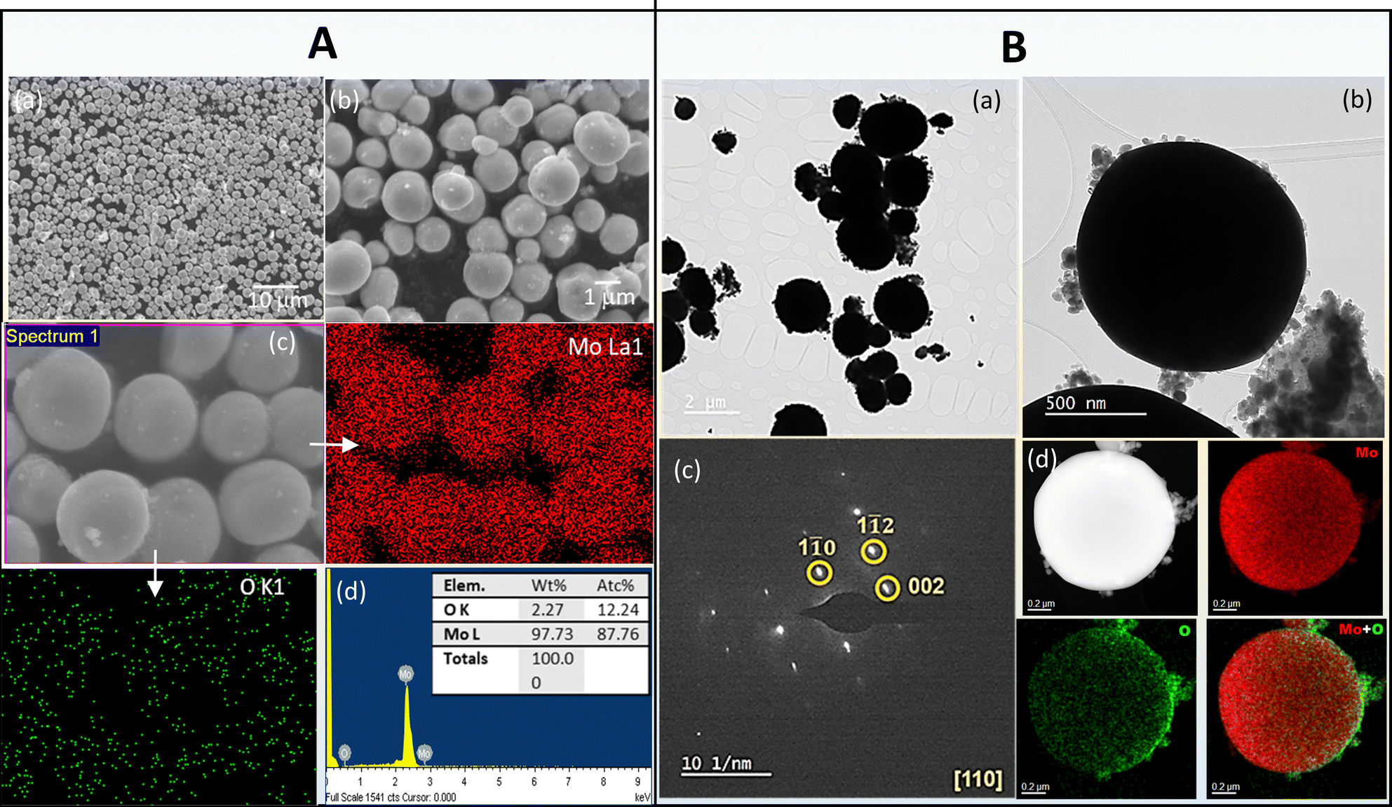 | ||
| Fig. 4 (A). ((a) and (b)) SEM images of spherical Mo particles; (c) SEM/EDS mapping images; (d) SEM/EDS spectra (inset is elemental analysis data); (B). ((a) and (b)) TEM images; (c) SAED pattern; (d) TEM/EDS mapping. | ||
TEM analysis of Mo synthesized at 800 °C for 2 hours revealed spherical Mo particles with small particles attached to their surface (Fig. 4B(a and b)).
These tiny particles contain Mo, Zn, and O. The SAED pattern in Fig. 4B(c) shows (1![[1 with combining macron]](https://www.rsc.org/images/entities/char_0031_0304.gif) 0), (12), and (002) planes of Mo in the [110] direction. Moreover, TEM/EDS mapping of a microsphere demonstrates that the oxygen distribution on its surface is not uniform, potentially due to small particles partially attached to the microsphere's surface (Fig. 4B(d)).
0), (12), and (002) planes of Mo in the [110] direction. Moreover, TEM/EDS mapping of a microsphere demonstrates that the oxygen distribution on its surface is not uniform, potentially due to small particles partially attached to the microsphere's surface (Fig. 4B(d)).
3.4. Raman shift, BET surface, and XPS spectra
Further characterization of the Mo powder was carried out using Raman, BET, and XPS spectroscopies, three widely used techniques in materials science. The corresponding data are presented in Fig. 5(a–d) and Fig. S5 (ESI†). In Fig. 5(a), the Raman band positions perfectly coincide with those of α-MoO3, a critical observation that aids in identifying the material. The Raman modes for α-MoO3 can be described as Γ = 8Ag + 8B1g + 4B2g + 4B3g + 4Au + 3B1u + 7B2u + 7B3u where Ag, B1g, B2g, B3g are Raman active, Au is an inactive, and others are infrared-active modes.40,41 The Raman data also reveals that the surface of Mo is covered by an oxide layer, which serves as the primary source of oxygen within the Mo powder. This finding has implications for the material's reactivity and stability. | ||
| Fig. 5 (a) Raman spectra of Mo powder (800 °C); (b) adsorption/desorption isotherms of Mo (500 °C); (c) full XPS spectra of Mo powder (800 °C); (d) Mo spectra with Gaussian fitting. | ||
The adsorption–desorption isotherms for Mo derived at 500 °C are shown in Fig. 5b. This isotherm resembles type-II, which is highly common in physical adsorption in powdered samples. The typical hysteresis loop (H3 type) between the desorption and adsorption branches indicates the sample has macroporous structure, which may arise due to the agglomeration of particles. The inset of Fig. 5b shows the BJH pore volume according to pore diameter. According to the inset, the Mo exhibit a broad size distribution, reaching a maximum at 47 nm, thus indicating the mesoporous-macroporous nature of Mo nanoparticles. The following BET surface area values were obtained for Mo samples synthesized at various temperatures: 20.58 m2 g−1 (Mo-500 °C), 5.34 m2 g−1 (Mo-700 °C), 1.75 m2 g−1 (Mo-800 °C, 2 hours) and 0. 73 m2 g−1 (800 °C 20 hours). The oxygen concentration in Mo powder determined by Eltra ONH-2000 O/N analyzer shows strong decreasing tendency with processing time: 1.82 wt% (800 °C, 2 h), 0.74 wt% (800 °C, 10 h) and 0.35 wt% (800 °C, 20 h).
XPS analysis was conducted on the Mo microspheres obtained from the MoO3 + 10Zn mixture after 2 hours of treatment at 800 °C (Fig. 5(c)). The most peaks identified on the Mo particle surface are Mo 3d, O 1s, Zn 2P, and C 1s. Mo 3d peak after Gaussian fitting shows three peaks with 228.12337, 232.08, and 235.10075 eV binding energies42 (Fig. 5(d)). These peaks correspond to Mo6+ (3d5/2), Mo6+ (3d3/2), and Mo4+ (3d5/2) electronic states, confirming the presence of MoO3 and MoO2 on the particle surface. Moreover, besides molybdenum oxides, Zn 2p3/2 and Zn 2p1/2 states possibly indicate the presence of Zn-containing phases (Fig. S5 (ESI†)). Based on the XPS analysis data, we can infer that the presence of Zn 2p3/2 and Zn 2p1/2 states is attributed to small particles with ZnMoxOy composition. XPS analysis also detected a C 1S peak at 284.0 eV and an N 1s peak at 398.08 eV (Fig. S5 (ESI†)). The C 1s peak is associated with sp2 hybridized carbon, but its origin is unclear. Similarly, the origin of the N 1s peak is also ambiguous (Fig. S5 (ESI†)). The argon gas used in the experiments may source these impurities.
3.5. Growth kinetics of Mo microsphere
Based on the SEM analysis, the growth behavior of the Mo microsphere can be explained by the Ostwald ripening (OR) theory,43 where smaller particles vanish as larger ones grow. To determine the growth kinetics of the Mo microsphere, the diameter of the microsphere was assessed at different processing temperatures and times. Fig. 6(a) shows the particle size growth tendency upon the heating temperature. The particle size visibly increases between 500 and 600 °C, remaining within the nano range (≤100 nm). At 700 °C, the particles begin to spheroidize, and the sphere's diameter increases rapidly with temperature, reaching ∼2.0 μm at 850 °C. Above 850 °C, the growth rate slows down and strives for saturation. | ||
| Fig. 6 Growth tendency of Mo spheres: (a) upon the processing temperature; (b) upon the heating time; (c) data presented in D3 − Do3/t coordinates; (d) Mo diameter-growth rate relation. | ||
The impact of the holding time at 800 °C on the sphere's diameter was also examined and depicted in Fig. 6(b). This distribution can be divided into two zones: 1st zone (0–1 hours), where the particle growth has a linear character, and 2nd zone (2–20 hours), where the particle diameter growth takes a parabolic character. To calculate particle growth kinetics based on the diameter–time relationship, we utilized the standard model from the Lifshitz–Slyozov–Wagner (LSW) theory, which describes the growth kinetics of particles during Ostwald ripening.43 According to the LSW theory, the relationship between particle diameter and time can be characterized by:
| D3 − Do3 = Kt | (5) |
| γ = K/3D2 | (6) |
By eqn (6), we calculated the growth rate of microspheres based on their size (Fig. 6(d)). It is evident that as the diameter of a microsphere increases from 0.5 to 10 μm, the growth rate decreases by almost two orders of magnitude.
The Mo particle has a unique spherical shape maintained during coarsening through the Ostwald ripening process. The liquid Zn medium drives the formation of spherical particles. The nature of the fluid medium and van der Waals interaction between the liquid and nanoparticles play a critical role in particle aggregation, attachment, assembly, and shaping.44,45 In the Mo–Zn system, two main factors are essential: the melting of Zn and forming MoZn6 alloy. In this scenario, the growth of the Mo microsphere can be described as a complex process with several steps. The interfacial morphologies are primarily influenced by diffusion in the liquid and solid phases.
A thermochemical scheme for the growth process of the Mo microsphere can be suggested as follows:
-Reduction of MoO3 and Mo nuclear formation (500–600 °C)
| MoO3(sol.) + 10Zn(liq.) → Mo (sol.) +3ZnO (sol.) + 7Zn (liq.) | (7) |
-MoZn6 alloy phase formation (600–650 °C)
| Mo (sol.) + 7Zn (liq.) → MoZn6 (liq.) + Zn (liq.) | (8) |
-Decomposition of MoZn6 (650–750 °C)
| MoZn6 (liq.) → Mo (sol.) + 6Zn (liq.) | (9) |
-Growth of microsphere by liquid phase sintering (750–850 °C)
| Mo(sol.) + Zn (liq.) → Mo (sol.) (larger diameter) + Zn(liq.) | (10) |
During the liquid phase sintering, liquid zinc helps reduce particles' surface energy, allowing them to come together and form larger ones. The examination under the SEM shows that the growth of micrometer-sized microspheres mainly happens when two or more similar particles merge to form a larger one. This merging process, facilitated by the presence of liquid zinc, resembles the mechanism of liquid phase sintering. As evidence of this mechanism, SEM/EDS analysis always reveals the presence of 1–3 wt% zinc in molybdenum (Mo) microspheres before vacuum distillation. However, following vacuum distillation, the zinc completely evaporates from the microspheres, while the spherical shape of the particles remains intact.
It is important to note that a similar study involving the WO3 + kZn system produced round-shaped tungsten (W) nanoparticles measuring 100 nm in size (refer to Fig. S6, ESI†). However, unlike the Mo-system, there was no increase in particle size and further spherodization. A similar result was obtained from the MoO3 + 30 Mg mixture at 800 °C. As demonstrated in Fig. S7 (ESI†), the growth of Mo particles in liquid Mg did not result in the formation of nano- and microspheres, yielding only Mo nanoparticles.
This suggests the significance of intermediate MoZn6 alloy phase formation and its important role in Mo particles spherodization process.
3.6. Electrocatalytic performance in hydrogen evolution reaction (HER)
Mo samples prepared at 500, 700, and 800 °C (2 h) were tested as electrocatalysts in HER. The electrocatalytic performance was conducted in a 0.5 M H2SO4 solution using a three-electrode system as depicted in Fig. S8 (a) (ESI†). The polarization curves shown in Fig. 7(a) represent the measured CV values at 100th cycle for each sample. Under the specified testing conditions, all three samples show good cycling stability within 100 cycles (Fig. S8, (b–d), ESI†). The current density for the Mo sample synthesized at 500 °C shows a significant change in the positive potential region (Fig. 7(a)). Our visual inspection couldn’t detect H2 evaluation in the −0.2 to 0.1 V potential range, and the 27 mV overpotential at 10 mA cm−2 is not related to the H2 evaluation process and can be conditioned by the gas-phase sorption of hydrogen ions on counter electrode.46 In this sample, the evaluation of H2 starts >200 mV, particularly its overpotential at 20 mA cm−2, is determined to be 206 mV. The polarization curves of Mo samples synthesized at 700 and 800 °C have typical catalytic character, and the overpotential at 10 mA cm−2 is 205 and 170 mV, correspondingly (Fig. 7(a)). As one can see, the catalytic activity of Mo samples is not determined by specific surface area since Mo-800 with the lowest surface area (1.75 m2 g−1) shows the lowest overpotential (170 mV) and the highest catalytic activity. As expected, the Tafel slopes are also low, 40 mA dec−1 for Mo-800 and Mo-700 and 50 dec−1 for Mo-500 (Fig. 7(b)). The relatively low values for the Tafel slope mean higher current density can be reached with relatively low overpotential. The large-scale polarization curves shown in Fig. 8(e–g) (ESI†) demonstrate that up to 350 mA cm−2 is achieved without losing the stability of catalysts.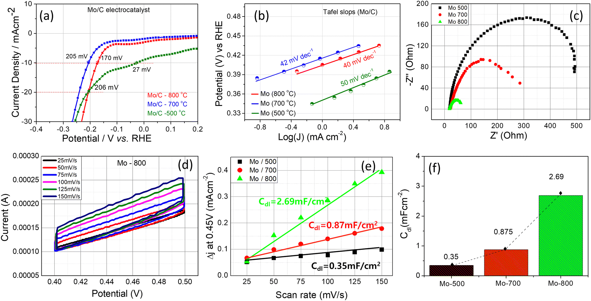 | ||
| Fig. 7 (a) The polarization curves of Mo-containing catalysts synthesized at different temperatures: (a) 500 °C, (b) 700 °C, (c) 800 °C; (b) Tafel slopes; (c) Nyquist plot derived from the electrochemical impedance spectra; (d) CV curves for Mo-800 recorded in the non-faradaic regions; (e) average non-faradaic current density (Δj = (ja − jc)/2) obtained from CV curves at 0.45 V as a function of the scan rate; (f) the change of Cdlvs. the type of catalyst. | ||
 | ||
| Fig. 8 (a) The pure Mo and surface oxidized Mo slabs for the (001), (110) and (211) planes used in the calculations; (b) Side view of the differential charge density plots of the stable adsorption configuration of H on the Mo surface with and without the oxide layer. (isosurface value is 0.05 e Å−3). | ||
To gain more insight into the electrode kinetics of Mo catalysts under the HER conditions, EIS measurements on the catalysts were conducted over the same potential range and pH 0.5. As shown in Fig. 7(c), Nyquist plot of each catalyst was measured using their overpotentials at current density 10 mA cm−2. The Rct values decrease from Mo-800 to Mo-500, conforming that the catalytic activity of Mo samples increases with increasing the synthesis temperature.
CV tests in non-faradaic regions was also conducted at various scan rates (25–150 mV s−1) to estimate the double layer capacitance (Cdl) of Mo catalysts. Fig. 7(d) illustrates the measured representative CVs for the Mo-800 catalysts (see Fig. S9 in ESI† for corresponding CVs for Mo-700 and Mo-500). The Cdl was determined from CV using the equation:47
| Cdl = Δj(ja − jc)/2ν | (11) |
Faradaic efficiency of Mo-catalysts was calculated following the protocols described in49 and described in ESI† (Section 7, Fig. S10 and S11). The H2 generating rate is calculated as 0.61 mL min−1, and the faradaic efficiency approaches nearly 83.7% at 2.82 V. For comparison the faradaic efficiency of commercial Pt/C electrocatalyst is 81.98–85.97%, at 1.5–1.8 V respectively.50 This means that Mo/C electrocatalysts demonstrate sufficiently high faradaic efficiency.
Mo and Mo-supported MoS3 electrocatalysts on a FTO substrate for HER in 0.5 M H2SO4 solution demonstrated the following overpotentials: FTO/Mo – 326 mV, FTO/α-MoS3 – 520 mV, and FTO/Mo/α-MoS3 – 247 mV.51 Other non-noble metals as electrocatalysts for HER are rare, and there is limited data in the literature.52 Among the non-noble metals, Ni is the most well-known electrocatalyst, so a comparison can be made between Ni and Ni–Mo electrocatalysts. Ni has a lower hydrogen adsorption free energy (ΔGH+ = −0.15 eV) than Mo (ΔGH+ = −0.38 eV),53 and consequently, it is expected to show better electrochemical performance. However, pristine Ni has a very high overpotential (>500 mV), and the overpotential of pristine Mo–Ni electrode is about 270–280 mV.52 The significantly low overpotential of Mo-800 (170 mV) indicates that the current synthesis process may produce Mo spheres with high surface activity and improved catalytic performance for water splitting.
Note that the Tafel slopes of Mo samples at 10 mA cm−2 current density are almost comparable with the commercial Pt/C catalyst.54 We believe further research on this material can be attractive to lower the overpotential and fabricate an inexpensive and effective catalyst for water splitting.
3.7. DFT analysis of hydrogen adsorption and Gibbs free energy on Mo surface
Through XRD analysis, the Mo powder synthesized in this study exhibited diffraction patterns corresponding to the (001), (110), and (211) planes. Therefore, the hydrogen adsorption energies for each crystal plane were calculated using DFT analysis. As a result of the TEM analysis in Fig. 4(d), several atomic layers of thick oxides were present on the Mo surface, so calculations were performed separately between the clean Mo surface and the Mo layer covered by oxygen. The pure Mo and surface oxidized Mo slabs for the (001), (110) and (211) planes used in the calculations are shown in Fig. 8(a). Each slab was optimized to calculate the adsorption energy, and the optimized slabs after hydrogen adsorption on the surface-oxidized Mo slab are shown in the last two rows.The calculation results for the planes are depicted in Table 1.
| Mo slab surface conditions for H adsorption | ΔGH*, adsorption Gibbs free energy, eV | |
|---|---|---|
| (001) | On clean Mo | −1.0254 |
| On oxygen-adsorbed Mo | −0.7554 | |
| (110) | On clean Mo | −0.9935 |
| On oxygen-adsorbed Mo | −1.1254 | |
| (211) | On clean Mo | −1.683 |
| On oxygen adsorbed Mo | −1.0761 | |
The calculated Gibbs free energy of hydrogen adsorption for clean Mo slab immensely differs from the |0.2| eV typically reported for suitable catalysts. This indicates that metal Mo has a strong interaction with hydrogen and is easy to adsorb. Still, it may be difficult to escape into the gas phase after hydrogen molecules are formed.
Among the three planes considered in the calculation, the hydrogen adsorption energy of the (211) plane has the most significant negative value, so the contribution of Mo to the catalytic properties is not expected to be significant. Notably, the hydrogen adsorption energy of Mo in the presence of a surface oxide layer decreases drastically for facets (001) and (211).
Fig. 8(b) illustrates the differential charge density plots of stable hydrogen (H) adsorption configurations on a molybdenum surface with and without an oxide layer. The yellow area surrounding the atom denotes an augmentation in the charge density of the bonding region. In contrast, the blue area signifies a reduction in the charge density of the bonding region.
As shown in Fig. 8(b), a charge transfer occurs between Mo atoms and hydrogen atoms on a pure Mo surface, decreasing charge density at the lower part of the surface of Mo atoms. Conversely, in the presence of an oxide, the Mo–O bond is stable, and it can be observed that electron transfer occurs between oxygen atoms and hydrogen atoms. In other words, when hydrogen is stably adsorbed on the surface of oxidized Mo, Mo, and oxygen atoms in the adsorption system, it loses some electrons, and the charge density in the Mo–O bonding region decreases, thus maintaining the Mo–O bond. It is hypothesized that the interaction between Mo and O facilitates higher adsorption energy for hydrogen than that observed on a pristine Mo surface, except the (110) plane. This is postulated to be due to the aligned and dense arrangement of Mo atoms on the (110) plane, which does not exhibit an offsetting effect on the adsorption energy by the surface oxide layer.
3.8. Vacuum distilled zinc
After the thermal processing, the zinc particles shape themselves after being deposited on the ‘cold’ walls of the nickel pipe. Depending on the zone temperature where the zinc vapor was condensed, the shape and size of the particles can change from spherical to facet-exposed spherical to dendritic structures. To illustrate this, the cold end part of the stainless steel pipe was divided into four zones, as indicated in Fig. 9A(a). The corresponding SEM images shown in Fig. 9A(a) display the schematic of the reaction pipe, highlighting a selected zone where the different shapes of zinc particles after evaporation-condensation were observed. In zone (I), with the lowest temperature, the particles are spherical, and the size ranges from 2–5 μm (Fig. 9A(b)). In zone (II), the merging of particles into larger ones occurs (Fig. 9A(c)). The large spherical particles partially transform into truncated hexagons (Fig. 9A(d)). In zone (III), almost all particles are truncated hexagons (Fig. 9A(e)). In zone (IV), the process of dendritic crystallization occurs, during which all spherical particles and hexagons turn into millimeter-sized dendrites (Fig. 9A(f)). Among the observed structures, the truncated hexagons are the most intriguing. These structures, under different magnifications, are depicted in Fig. 9B. Crystals with varying facets, such as {0001}, {100}, and {11![[2 with combining macron]](https://www.rsc.org/images/entities/char_0032_0304.gif) 1}, can be seen.
1}, can be seen.
 | ||
| Fig. 9 (A) Spherical Zn particles obtained after evaporation-condensation: (a) condensation zones: (b) I zone; (c) and (d) II zone; (e) III zone; (f) IV zone. (B). Zn spherical particles under the different magnifications: (a) ×1000; (b) ×3000; (c) ×4500; (d) ×8000. | ||
In summary, while spherical particles have lower surface energy, the formation of a crystal structure is favored during crystallization because it leads to a lower total Gibbs free energy of the system. The internal energy savings from the ordered crystal lattice outweigh the costs associated with the increased surface energy of the faceted crystal. The transition to faceted crystals is likely to occur during the cooling near the Zn melting point, similar to the behavior of gold particles, as reported in.55–57
4. Conclusion
This study introduces a novel, attractive, low-temperature approach for producing Mo microspheres, a significant advancement in the field. The procedure involves heating a mixture of MoO3 + kZn (where k represents the moles of Zn) in a non-reactive environment at temperatures ranging from 500 to 850 °C. An excess of zinc was used during the synthesis to reduce the chemical heat of the reaction and facilitate the nucleation and growth of Mo microspheres in a liquid Zn medium. Microspheres with diameters ranging from 0.3 to 8.0 μm are obtained through the acid leaching of the reaction product. The formation of MoZn6 alloy in the intermediate stages of reaction and its active role in the spherodization process is demonstrated. The growth rate of the microspheres, as determined by the diameter–time relationship, is 5 × 10⁻³ to 10−5 μm min−1, depending on the diameter. It was demonstrated that the Ostwald ripening model can describe the growth kinetics of Mo microspheres, including the reaction constant and the growth rate of microspheres. Molybdenum (Mo) microspheres have been investigated as electrocatalysts for the hydrogen evolution reaction (HER), where they exhibited a lowest overpotential of 170 mV and a Tafel slope of 40 mV dec−1. As a result of DFT calculations, it was found that the hydrogen generation catalytic behavior of Mo particles is influenced by the offsetting effect of hydrogen adsorption energy due to the interaction between oxygen and Mo atoms on the surface. Meanwhile, there was a variation in the morphology of evaporated-condensed zinc, transitioning from microspheres to exposed facets and dendritic crystals.Author contributions
Jong Hyeon Lee - software, conceptualization, data curation, supervision; Hayk Nersisyan - methodology, investigation, data curation, analysis, writing – original draft; Junmo Jeong - investigation, formal analysis; Hoyoung Suh - formal analysis.Data availability
The datasets supporting this article have been uploaded as part of the ESI.†Information about DFT calculation, including calculation codes and video files, will be presented by request.
Conflicts of interest
There are no conflicts to declare.Acknowledgements
This work was supported by the National Research Foundation of Korea(NRF) grant funded by the Korean government (MSIT)(RS-2024-00394058), and this work was supported by the research fund of Chungnam National University.Notes and references
- M. Ortiz and T. Herrera, Molybdenum: Characteristics, production and applications, Nova Science Pub Inc, UK, ed. edition, 2012 Search PubMed.
- R. Burman, Properties and applications of molybdenum, ASTM International, USA, 1984 Search PubMed.
- V. S. Saji and S. L. Lopatin, Molybdenum and its compounds: Applications, electrochemical properties, and geological implications, Nova Science Pub Inc, UK, ed. edition, 2014 Search PubMed.
- R. A. Mir, S. Upadhyay and O. P. Pandey, A review on recent advances and progress in Mo2C@C: A suitable and stable electrocatalyst for HER, Int. J. Hydrogen Energy, 2023, 48, 13044–13067 CrossRef CAS.
- J. Dong, Q. Wu, C. Huang, W. Yao and Q. Xu, Cost-effective Mo-rich Mo2C electrocatalysts for the hydrogen evaluation reaction, J. Mater. Chem. A, 2018, 6, 10028–10035 RSC.
- X. Yang, J. Cheng, X. Yang, Y. Xu, W. Sun and J. Zou, Facet-tunable coral-like Mo2C catalyst for electrocatalytic hydrogen evaluation reaction, Chem. Eng. J., 2023, 451, 138977 CrossRef CAS.
- T. V. Nguyen, M. Tekalgne, T. P. Nguyen, Q. V. Le and S. H. Ahn, Electrocatalysts based on MoS2 and WS2 for hydrogen evolution reaction: An overview, Battery Energy, 2023, 2, 20220057 CrossRef.
- Y. Xu, R. Ge and J. Yang, et al., Molybdenum disulfide (MoS2)-based electrocatalysts for hydrogen evolution reaction: From mechanism to manipulation, J. Energy Chem., 2022, 74, 45–71 CrossRef CAS.
- X. Zhou, Z. Yu and Y. Yao, et al., A high-efficiency Mo2C electrocatalyst promoting the polysulfide redox kinetics for Na-S batteries, Adv. Mater., 2022, 34, 2200479 CrossRef CAS.
- K. Ba, G. Wang and T. Ye, et al., Single faceted two-dimensional Mo2C electrocatalyst for highly efficient nitrogen fixation, ACS Catal., 2020, 10, 7864–7870 CrossRef CAS.
- X. Ren, J. Zhao and Q. Wei, et al., High-performance N2-to-NH3 conversion electrocatalyzed by Mo2C nanorod, ACS Cent. Sci., 2019, 5, 116–121 CrossRef CAS PubMed.
- B. Chang, H. Yuan and L. Li, et al., Enhancing electrochemical nitrogen fixation by mimicking p back-donation on laser-tuned Lewis acid sites in noble-metal-molybdenum carbide, Appl. Catal., B, 2023, 320, 121777 CrossRef.
- I. Usolsev, R. Eichler and Y. Wang, et al., Decomposition studies of group 6 hexacarbonyl complexes: Part 1: Production and decomposition of Mo(CO)6 and W(CO)6, Radiochim. Acta, 2015, 104, 2445 Search PubMed.
- J. C. Li, H. J. Shim, J. H. Kim, M. Ji, J. Byun and Y. I. Lee, Spray pyrolysis-based synthesis of pure molybdenum powder with nanoscale primary particles and its sintering characteristics, Int. J. Refract. Met. Hard Mater., 2024, 118, 106492 CrossRef.
- G.-S. Kim, H. G. Kim, D.-G. Kim, S.-T. Oh, M.-J. Suk and Y. D. Kim, Densification behavior of Mo nanopowders prepared by mechanochemical processing, J. Alloys Compd., 2009, 469, 401–405 CrossRef CAS.
- B. Liu, H. Gu and Q. Chen, Preparation of nanosized Mo powder by microwave plasma chemical vapor deposition method, Mater. Chem. Phys., 1999, 59, 204–209 CrossRef CAS.
- X. Liu, K. Wang, Q. Chen, B. Zhang, P. Hao, Y. Wang and Q. Wang, Controllable synthesis of spherical molybdenum nano-powders by one-step reduction of APM in radio frequency hydrogen plasma, Materials, 2022, 15, 15062019 Search PubMed.
- S. Gu, M. Qin, H. Zhang, J. Ma and X. Qu, Preparation of Mo nanopowders through hydrogen reduction of a combustion synthesized foam-like MoO2 precursor, Int. J. Refract. Met. Hard Mater., 2018, 76, 90–98 CrossRef CAS.
- D.-H. Wang, G.-D. Sun and G.-H. Zhang, Preparation of ultrafine Mo powders via carbothermic pre-reduction of molybdenum oxide and deep reduction by hydrogen, Int. J. Refract. Met. Hard Mater., 2018, 75, 70–77 CrossRef CAS.
- M. Saghafi, A. Ataie and S. Heshmati-Manesh, Effects of mechanical activation of MoO3/C powder mixture in the processing of nano-crystalline molybdenum, Int. J. Refract. Met. Hard Mater., 2011, 29, 419–423 CrossRef CAS.
- Z. Huang, J. Liu, X. Deng, H. Zhang, L. Lu, Z. Hou and S. Zhang, Low-temperature molten salt preparation of molybdenum nanoparticles, Int. J. Refract. Met. Hard Mater., 2016, 54, 315–321 CrossRef CAS.
- H. H. Nersisyan, J. H. Lee and C. W. Won, The synthesis of nanostructured molybdenum under self-propagating high-temperature synthesis mode, Mater. Chem. Phys., 2005, 89, 283–288 CrossRef CAS.
- C. W. Won, H. H. Nersisyan, H. I. Won and J. H. Lee, Refractory metal nanopowders: synthesis and characterization, Curr. Opin. Solid State Mater. Sci., 2009, 14, 53–68 CrossRef.
- H. H. Nersisyan, J. H. Lee, J. R. Ding, K. S. Kim, K. V. Manukyan and A. S. Mukasyan, Combustion synthesis of zero-, one-, two-and three-dimensional nanostructures: current trends and future perspectives, Prog. Energy Combust. Sci., 2017, 63, 79–118 CrossRef.
- D. Davtyan, R. Mnatsakanyan and S. L. Kharatyan, Reduction of MoO3 by Zn: Reducer migration phenomena, Int. J. Refract. Met. Hard Mater., 2010, 28, 601–604 CrossRef CAS.
- S. K. Ko, C. W. Won, S. S. Cho and B. S. Chun, Zinc reduction of MoO3 in a self-propagating high-temperature synthesis process, Metall. Mater. Trans. B, 1996, 27, 315–318 CrossRef.
- A. Hoseinpur, M. Jalaly, M. S. Bafghi, J. V. Khaki and M. Sakaki, The effect of preliminary mechanical activation on the zinc loss control in combustive reduction of MoO3 by Zn, Int. J. Refract. Met. Hard Mater., 2016, 54, 251–259 CrossRef CAS.
- Q. Sha, B. K. Chen and C. S. Xiang, Preparation and properties of spherical Mo powders by plasma rotating electrode process for additive manufacturing, Mater. Sci. Forum, 2020, 993, 391–397 Search PubMed.
- X. Liu, K. Wang, Q. Chen, B. Zhang, P. Hao, Y. Wang and Q. Wang, Controllable preparation of spherical molybdenum nano-powders by one-step reduction of APM in radio frequency hydrogen plasma’, Materials, 2022, 15, 15062019 Search PubMed.
- Y. W. Sheng, Z. M. Guo and J. J. Hao, Characterization of spherical molybdenum powder prepared by RF plasma processing, Adv. Mater. Res., 2012, 482–484, 2563–2567 CAS.
- X. Liu, K. Wang, P. Hu, Q. Chen and A. A. Volinsky, Spherodidization of molybdenum powder by radio frequency thermal plasma, Int. J. Miner. Metall. Mater., 2015, 22, 1212–1218 CrossRef CAS.
- S. Tkachenko, C. O. Urrutia and O. Ksenzova, et al., Production of spherical Mo and Mo-Si powders by spray drying of Si suspension in a water-soluble Mo precursor, Adv. Powder Technol., 2024, 35, 104313 CrossRef CAS.
- N. Qureshi, S. Arbuj, M. Shinde, S. Rane, M. Kulkarni, D. Amalnerkar and H. Lee, Swift tuning from spherical molybdenum microspheres to hierarchical molybdenum disulfide nanostructures by switching from solvothermal to hydrothermal synthesis route, Nano Convergence, 2017, 4, 2–5 CrossRef PubMed.
- S. Field, A.R.C. Sc, The commercial electrolysis of zinc sulphate solutions, Trans. Faraday Soc., 1921, 16, 492–500 RSC.
- I. W. Wark, The electrodeposition of zinc from acidified zinc sulphate solution, J. Appl. Electrochem., 1979, 9, 721–730 CrossRef CAS.
- A. A. Shiryaev, Thermodynamics of SHS processes: An advanced approach, Int. J. Self-Propag. High-Temp. Synth., 1995, 4, 351–362 CAS.
- J. K. Norskov, T. Bligaard, A. Logadottir, J. R. Kitchin, J. G. Chen and S. Pandelov, Stimming Trends in the exchange current for hydrogen evaluation, J. Electrochem. Soc., 2005, 152, J23–J26 CrossRef CAS.
- H. H. Nersisyan, H. I. Won, C. W. Won and K. C. Cho, Combustion synthesis of nanostructured tungsten and its morphological study, Powder Technol., 2009, 189, 422–425 CrossRef CAS.
- S. V. Boyarchenko, P. M. Kostin, S. A. Krishenik and A. E. Rogachev, Sytchev, Combustion of layered SHS systems: Thermal conditions at the interface, Int. J. Self-Propag. High-Temp. Synth., 2015, 24, 115–118 CrossRef.
- O. Lupan, V. Trofim and V. Cretu, et al., Investigation of optical properties and electronic transitions in bulk and nano-microribbons of molybdenum trioxide, J. Phys. D: Appl. Phys., 2014, 47, 085302 CrossRef CAS.
- S. Kumar, S. Paterl and K. Dewwangan, et al., Synthesis of □-MoO3 nanofiber for enhanced field-emission properties, Adv. Mater. Lett., 2018, 9, 585–589 CrossRef.
- G. Tai, T. Zeng and J. Yu, et al., Fast and large-area growth of uniform MoS2 monolayers on molybdenum foils, Nanoscale, 2016, 8, 2234–2241 RSC.
- A. Baldan, Review Progress in Ostwald ripening theories and their applications to nickel-base superalloys Part I: Ostwald ripening theories, J. Mater. Sci., 2002, 37, 2171–2202 CrossRef CAS.
- I. M. Lifshitz and V. V. Slyozov, The Kinetics of Precipitation from Supersaturated Solid Solutions, J. Phys. Chem. Solids, 1961, 19, 35–50 CrossRef.
- J. Lee, E. Nakouzi and J. Heo, et al., Effects of particle shape and surface roughness on van der Waals interactions and coupling to dynamics in nanocrystals, J. Colloids Interface Sci., 2023, 652, 1974–1983 CrossRef CAS.
- R. K. Singh, R. Ramesh, R. Devivaraprasad, A. Chakraborty and M. Neergat, Hydrogen interaction (electrosorption and evaluation) characteristics of Pd and Pd3Co alloy nanoparticles: An In-situ investigation with electrochemical impedance test, Electrochem. Acta, 2016, 194, 199–210 CrossRef CAS.
- N. K. Shrestha, S. A. Patil, J. Han, S. Cho, A. I. Inamdar, H. Kim and H. Im, Chemical etching induced microporous nickel backbones decorated with metallic Fe@hydroxide nanocrystals: an efficient and sustainable OER anode toward industrial alkaline water-splitting, J. Mater. Chem. A, 2022, 10, 8989–9000 RSC.
- X. Long, G. Li, Z. Wang, H. Zhu, T. Zhang, S. Xiao, W. GuO and S. Yang, Mettalic iron-nickel sulfate ultrathin nanosheets as a highly active electrocatalyst for hydrogen evaluation reaction in acidic media, J. Am. Chem. Soc., 2015, 137, 11900–11903 CrossRef CAS PubMed.
- Y. Li, J. Chen, P. Cai and Z. Wen, Electrochemical neutralization energy assisted low-cost acid-alkaline electrolizer for energy-saving electrolysis hydrogen generation, J. Mater. Chem. A, 2018, 6, 4948–4954 RSC.
- D. H. Kweon, M. S. Okyay and S. J. Kim, et al., Ruthenium anchored on carbon nanotube electrocatalyst for hydrogen production with enhanced Faradaic efficiency, Nat. Commun., 2020, 11, 1278 CrossRef CAS PubMed.
- B. Liu, Z. Jin, L. Bai, J. Liang, Q. Zhang, N. Wang, C. Liu, C. Wei, Y. Zhao and X. Zhang, Molybdenum-supported amorphous MoS3 catalyst for efficient hydrogen evaluation in solar-water-splitting devices, J. Mater. Chem. A, 2026, 4, 14204–14212 RSC.
- L. Huo, C. Jin, K. Jiang, Q. Bao, Z. Hu and J. Chu, Applications of Nickel-based electrocatalysts for hydrogen evaluation reaction, Adv. Energy Sustainability Res., 2022, 3, 2100189 CrossRef CAS.
- S. H. Park, D. T. To and N. V. Myung, A review of nickel-molybdenum based hydrogen evaluation electrocatalysts from theory to experiment, Appl. Catal., A, 2023, 651, 119013 CrossRef CAS.
- N. Han, K. R. Yang and Z. Lu, et al., Nitrogen-doped tungsten carbide nanoarray as an efficient electrocatalyst for water splitting, Nat. Commun., 2018, 9, 924 CrossRef PubMed.
- P. Maity, S. Xie, M. Yamauchi and T. Tsukuda, Stabilized gold clusters: from isolation toward controlled synthesis, Nanoscale, 2012, 4, 4027–4037 RSC.
- T. Bull Tsukuda, Toward an atomic-level understanding of size-specific properties of protected and stabilized gold clusters, Chem. Soc. Jpn., 2012, 85, 151–168 CrossRef CAS.
- X. He, F. Cheng and Z. X. Chen, The lattice kinetic Monte Carlo simulation of atomic diffusion and structural transition for gold, Sci. Rep., 2016, 6, 33128 CrossRef CAS PubMed.
Footnote |
| † Electronic supplementary information (ESI) available. See DOI: https://doi.org/10.1039/d4qm00814f |
| This journal is © the Partner Organisations 2025 |