
 Open Access Article
 This Open Access Article is licensed under a
 Creative Commons Attribution 3.0 Unported Licence
The role of superlattice phases and interparticle distance in the magnetic behaviour of SPION thin films†
Marion
Görke
a,
Sherif
Okeil
a,
Guohui
Yang
b,
Hermann
Nirschl
b,
Thilo
Viereck
 cd and
Georg
Garnweitner
*ac
cd and
Georg
Garnweitner
*ac
aInstitute for Particle Technology (iPAT), Technische Universität Braunschweig, Volkmaroder Straße 5, 38104 Braunschweig, Germany. E-mail: g.garnweitner@tu-braunschweig.de
bInstitute of Mechanical Process Engineering and Mechanics (MVM), Karlsruhe Institute of Technology, Straße am Forum 7, 76131 Karlsruhe, Germany
cLaboratory for Emerging Nanometrology (LENA), Technische Universität Braunschweig, Langer Kamp 6 a/b, 38106 Braunschweig, Germany
dInstitute for Electrical Measurement Science and Fundamental Electrical Engineering (emg), Technische Universität Braunschweig, Hans-Sommer-Str. 66, 38106 Braunschweig, Germany
First published on 12th May 2025
Abstract
Superparamagnetic iron oxide nanoparticles (SPIONs) with tailored surface modifications were employed to fabricate ordered thin films through a drop-casting technique. By systematically varying the ligand chain length using stearic acid, decanoic acid, and hexanoic acid, we precisely controlled the interparticle distances within the films. Comprehensive investigations utilizing superconducting quantum interference device (SQUID) magnetometry elucidated the films’ superparamagnetic behaviour at room temperature, as well as notable exchange interactions at lower temperatures. Notably, these exchange characteristics exhibit a correlation with the blocking temperatures of the thin films. We postulate that these characteristics can be explained by different superlattice phases formed in the thin films, as indicated in previous studies, highlighting the profound influence of self-assembly and particle packing on the magnetic properties. To validate our hypothesis regarding the internal structure, we conducted grazing-incidence small-angle X-ray scattering (GISAXS) and scanning transmission electron microscopy (STEM) measurements, enabling us to assess the quality of internal ordering without compromising the integrity of the films. With this study we demonstrated how the use of simple building blocks, guided by the intrinsic driving force of self-assembly, can lead to remarkable magnetic properties in the resulting films.
Introduction
The field of magnetic nanoparticles has emerged as an area of research of major significance, attracting the attention of scientific researchers and engineering professionals alike due to the diverse range of potential applications across various disciplines. These nanoscale materials play a crucial role in the development of innovative solutions in medicine,1 energy, and environmental science.2 The incorporation of magnetic nanoparticles into films has the potential to enable versatile novel applications, because the adaptability of such films is remarkable.3 By adjusting the properties of the magnetic nanoparticles, including their material composition, size, shape, and surface modification, it is possible to modify the overall characteristics of the film to meet specific performance requirements. This enhances the versatility of these nanoparticles in diverse fields such as data storage,4,5 environmental sensing,6 and biomedical devices.7 For example, Furrer et al. were able to increase the recording areal density of SrFe-tapes by 14% compared to the one which was projected by the INSIC Tape roadmap for the year 2029.3,8 They decreased the size of the SrFe-nanoplatelets and improved the stability of the particles in the coating solution to improve the overall film quality in terms of smoothness, magnetisation strength and recording noise performance.One of the most common materials for magnetic nanoparticles is magnetite (Fe3O4), due to its distinctive magnetic properties and exemplary biocompatibility.9 Even though it is ferrimagnetic as bulk material, it becomes superparamagnetic when reduced to the nanometer size range, where each particle then acts as a single magnetic domain.10–13 In this state, magnetite nanoparticles do not retain magnetisation in the absence of an external magnetic field at room temperature. However, they exhibit high susceptibility, enabling them to efficiently respond to external magnetic fields. This superparamagnetic property is of great consequence for the preparation of stable dispersions and the enhancement of processability, as it prevents the undesirable magnetic attraction of particles during handling.
Even though superparamagnetic nanoparticles don't show any magnetic attraction towards each other in dispersion, they still possess some noteworthy interactions when they are brought into proximity, and this allows them to form organised assemblies through a variety of mechanisms.14–16 Close contact between these nanoparticles can result in the emergence of strong magnetic exchange interactions, which facilitate cooperative behaviour.17–19 Conversely, dipole interactions can prevail over longer distances, influencing the overall assembly dynamics.20,21 It is noteworthy that the nature and strength of these interactions can be precisely adjusted by modifying the interparticle distance, thereby enabling the control of assembly formation and functionality in superparamagnetic nanoparticle systems for a range of applications.22 The interparticle distance can be varied by the use of either “soft” spacers like polymers,23,24 aliphatic ligands25,26 and paraffin oil,12 or “hard” spacers like silica shells.25,27 Simultaneously, the type of spacer used can also affect the self-assembly properties of the nanoparticles.23,26
In this work, we synthesised SPIONs with ligands of various chain lengths on the particle surface and used a drop-casting technique to prepare magnetic thin films. The ligands were employed as “soft” spacers and were chosen to be of varying length to tune the interparticle distances in the films. These films received no further treatment to ensure that the self-assembly process was the main driving force for the film's structural characteristics, as well as the particle properties for the magnetic characteristics. The resulting films were investigated with regard to their magnetic properties and their structural features using techniques like SQUID magnetometry and GISAXS measurements. This allows us to get deeper insights into the influence of ligand length and concentration on the self-assembly process, as well as the magnetic interactions of SPIONs with various interaction distances in larger assemblies.
Methods
Synthesis of magnetite nanoparticles
The nanoparticles were synthesised after a procedure described in our previous publication.13 Iron(III) acetylacetonate (Fe(acac)3, 97%), dibenzyl ether (BE, 98%), stearic acid (SAc, technical grade, 90%), octadecylamine (OdAm, technical grade, 70%), decanoic acid (DAc, 98%), dodecylamine (DAm, 98%), hexanoic acid (HAc, 99.5%), heptylamine (HAm, 99%), and heptane (HPLC grade) were purchased from Sigma Aldrich. 1,2-Hexadecanediol (HDD, 98%) was purchased from TCI Chemicals. Ethanol (EtOH, HPLC grade) and methanol (MeOH, HPLC grade) were procured from Fisher Scientific.The precursor iron(III) acetylacetonate (2 mmol), the reducing agent HDD (10 mmol), BE as solvent (20 mL) and the ligands SAc/OdAm were added to a three-necked flask. The molar ratio of the ligands was kept constant at 3![[thin space (1/6-em)]](https://www.rsc.org/images/entities/char_2009.gif) :1 (acid:amine), but varied in the total amount with 12 mmol and 4 mmol. The reaction was carried out under a constant nitrogen flow. The reaction mixture was initially heated to 110 °C for a duration of 1 h. Thereafter, the temperature was elevated to 180 °C, where it was maintained for 2 h. Subsequently, a further increase to 300 °C was initiated, which was sustained for 1 h. The heating rate was 6.5 K min−1. Afterwards, the mixture was cooled down to room temperature and the formed nanoparticles were precipitated by adding MeOH. The particles were collected with a centrifuge (7000 rpm, 5 min), and washed three times by redispersion in hexane and precipitation with MeOH/EtOH (1:1 vol%). Finally, the obtained products were dried under vacuum for at least 24 h.
:1 (acid:amine), but varied in the total amount with 12 mmol and 4 mmol. The reaction was carried out under a constant nitrogen flow. The reaction mixture was initially heated to 110 °C for a duration of 1 h. Thereafter, the temperature was elevated to 180 °C, where it was maintained for 2 h. Subsequently, a further increase to 300 °C was initiated, which was sustained for 1 h. The heating rate was 6.5 K min−1. Afterwards, the mixture was cooled down to room temperature and the formed nanoparticles were precipitated by adding MeOH. The particles were collected with a centrifuge (7000 rpm, 5 min), and washed three times by redispersion in hexane and precipitation with MeOH/EtOH (1:1 vol%). Finally, the obtained products were dried under vacuum for at least 24 h.
This reaction procedure was performed for the shorter-chain ligands DAc/DAm and HAc/HAm in the same way, except that the final reaction temperature was 250 °C and 200 °C, respectively, taking into account the boiling temperature of the respective ligand. In the following discussion, only the terms SAc, DAc and HAc as notation for the ligand system (acid + corresponding amine) together with their respective total amounts (12 or 4 mmol) will be used to denote for the resulting particle products.
Thin film preparation
For the preparation of thin films, 25 mg of each sample was dispersed in 1 mL heptane and then 7 μL of the dispersion was dropped twice onto a silicon wafer, which previously had been cleaned with ethanol and acetone in a sonicator. Due to the hydrophilic nature of the wafer featuring a silica passivation layer, the droplets were spread on the surface via the pipet tip to ensure complete coverage. The wafer was placed in a closed container to slow down the evaporation for a better film quality. The drying time typically was about 15–20 min. No further heat or mechanical treatment was applied to the films.Characterisation
The magnetic measurements were carried out in an MPMS3 SQUID magnetometer from QuantumDesign. The silicon wafers with the films were taped to a glass sample holder to ensure a vertical alignment in the magnetic field. Powder samples were prepared on cotton in a gelatine capsule and mounted with a straw sample holder. M(H) measurements were carried out from −4 to 4 T at different temperatures, zfc/fc curves were measured at an applied field of 5 mT. To correct for remanent field issues at low fields, a Pd standard sample was measured with the same procedure as for the M(H) measurements and the actual magnetic field was calculated using the susceptibility (χg = 5.25 × 10⁻⁶ emu Oe−1 g−1) and mass (mPd = 0.2600 g) of the Pd-standard sample viaeqn (1). | (1) |
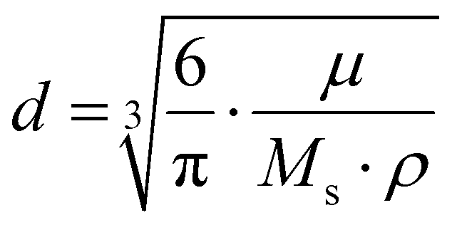
The particle size of the powder samples was subsequently calculated using the Langevin equation. First, the recorded magnetisation curves at 298 K were fitted with a Langevin plot according to eqn (2) to determine the saturation magnetisation MS and the particle magnetic moment μ:
 | (2) |
Using MS and μ from eqn (2), the magnetic particle size was then calculated from eqn (3):
 | (3) |
To determine the actual amount of iron oxide in the samples from the magnetic measurements, the gelatine capsules were completely dissolved in aqua regia at 80 °C after the magnetic measurement. The resulting solutions turned out bright yellow and were diluted with distilled water and their iron content determined with an ICP-OES (Varian ICP Expert II, 700-ES Series).
The blocking temperature TB was determined from the zfc/fc measurement of each sample using the following equation (eqn (4)):
 | (4) |
STEM measurements were performed on a scanning electron microscope (Thermo Scientific, Helios 5 UX DualBeam) with a STEM detector at 30 kV. The samples were prepared from a toluene dispersion onto TEM copper grids with a thin carbon layer. For image analysis, the ImageJ software was used. Size calculations were done based on at least 300 measured particles in various sample areas. TEM measurements were performed using a Tecnai G2 F20 TMP (FEI) instrument at 200 kV accelerating voltage.
Powder X-Ray Diffraction (XRD) was used to determine the crystallinity and crystallite size of each sample on a Si sample holder using Cu-Kα radiation (Empyrean Cu LFF HR goniometer, Almelo, Netherlands) in a 2θ range of 25 to 70° with 0.05° step size (Empyrean series 2, PANalytical PIXcel-3D detector, Almelo, Netherlands). The crystallite sizes were calculated via Rietveld refinement, using the PANalytical HighScore Plus software.
To determine the thickness of the nanoparticulate films, a small part of the film was removed by means of scratching the film with a copper needle. This resulted in a clean scratch that did not affect the Si wafer. Subsequently, the resulting height differences were measured by profilometry (Dektak XT, Bruker) utilising a diamond tip with a radius of 2 μm.28
To detect regular structures in the thin films without destroying them, Grazing-Incidence Small-Angle X-Ray Diffraction (GISAXS) was used. GISAXS experiments were performed using a Xeuss 2.0 Q-Xoom system (Xenocs SA, Grenoble, France), equipped with a Genix3D Cu ULC (ultra-low divergence) microfocus source emitting Cu Kα radiation (energy: 8.04 keV, wavelength: 1.5406 Å) and a Pilatus3 R 300 K two dimensional detector (Dectris Ltd, Baden, Switzerland). The Pilatus3 R 300 K is a hybrid pixel area detector with 487 × 619 pixels of 172 μm size (active area ∼84 × 107 mm2). The samples were placed at different distances from the detector (500–2500 mm) for a fixed exposure time of 600 s to collect 2D images covering a scattering vector (q) range from 0.003 to 0.2 Å−1. The images were treated with the Xenocs XSACT software via the “Grazing incidence” tool to perform a wedge correction. The wedge-corrected images were then treated via the “Data reduction” tool to obtain 1D SAXS curves (additional details can be found in the ESI†). The particle sizes/regular arrangement sizes were obtained via the “Guinier Law” tool, which uses the following equation (eqn (5)):
 | (5) |
The information about the particles’ size was obtained using the following equation, assuming spherical shape (eqn (6)):
 | (6) |
Results and discussion
The particles synthesised with the OAc, DAc and HAc ligand systems had been previously subjected to comprehensive characterisation by us using a range of techniques, including STEM, TEM, XRD, SQUID magnetometry and SAXS.13 The mean particle sizes of the nanoparticles were observed to be approximately 6 nm in all cases, and the particles exhibited a spherical morphology. All of the particles were found to be highly crystalline, exhibiting no signs of phase impurities and therefore displaying excellent magnetic properties. The principal conclusion of our preceding publication concerning these nanoparticles was that the final reaction temperature of the synthesis exerted a more pronounced influence on the nanoparticle characteristics than the quantity of ligand employed. As a result, nanoparticles synthesised at the same temperature with different amounts of ligand show highly similar properties. The particles synthesised with SAc were also characterised in terms of their physical size and shape, as well as their crystallite and magnetic size. Fig. 1 presents a comparison of the major characteristics of the obtained particles for all ligand systems. Again, we did not observe any larger differences in the properties of the 4 mmol and 12 mmol samples, further supporting our claim that the amount of ligand used for the synthesis does not have a major impact on the properties of the particles (small differences such as the larger particle size obtained from the XRD Rietveld evaluation can be explained by a centrifugation step prior to STEM analysis and film preparation). | ||
| Fig. 1 (a) Comparison of the sizes for all four ligand systems. The particle size was determined from STEM pictures (with standard deviation), the crystallite size was determined via Rietveld refinement from XRD measurements and the magnetic particle size was calculated with the Langevin function. (b) TEM picture of the 12 mmol SAc particles. (c) XRD measurements for the 12 mmol and 4 mmol SAc particles. The reference pattern is for magnetite (ICSD 98-009-8085). | ||
In order to evaluate the interactions of the particles in the thin films for the different types of particles and different particle distances, caused by the different ligand lengths, zfc/fc measurements were carried out and the blocking temperatures were determined (Table 1). A comparison of the blocking temperatures is already well known to describe the dipolar interactions between superparamagnetic nanoparticles with narrow size distributions.12,22 The blocking temperature ranges between 6.7 and about 54 K for the thin films. Two trends become visible when comparing the obtained values. First, the blocking temperature increases with increasing amount of ligand for the two shorter ligand systems, namely HAc and DAc. In contrast, the blocking temperature decreases with increasing amount of ligand in the two longer ligand systems, namely OAc and SAc. Second, contrary to the expected results, the blocking temperature does not increase with a shorter ligand length, i.e. higher particle interactions, but rather decreases.29,30 Usually, a smaller distance between superparamagnetic nanoparticles is known to lead to higher exchange interactions up to the point where the particles come into direct contact. This would then cause a rise in the blocking temperature, because the single particles, which exhibit quite low blocking temperatures due to their small size and high degree of thermal fluctuations, would start to interact with each other and therefore act as one large domain, which then possesses a higher blocking temperature due to a lowered affinity to thermal fluctuations.31,32 This was for example shown by Knobel et al., where the influence of the magnetic field during zfc/fc measurements was investigated, but also the difference between the blocking temperature of magnetite nanoparticles in defined arrays or random distributions.30 For these experiments particles from one batch were either distributed in paraffin (3D random system) or deposited using a Langmuir–Blodgett technique for ordered 2D assemblies. Also Toro et al. reported this phenomenon of rising TB with smaller interparticle distances.25 They synthesised maghemite nanoparticles which were coated in oleic acid and additionally coated part of the batch with silica shells of various thickness, to ensure defined interparticle distances. Afterwards the different particle systems were pressed into disks and further investigated. The observation that the blocking temperatures in our thin films exhibit an opposite trend suggests the presence of an additional effect beyond the scope of simple magnetostatic interactions between ferromagnets. A similar behaviour has been reported in various samples with antiferromagnetic and ferromagnetic phases and exchange bias effects.33,34 The blocking temperature for the OAc sample does not fit into this trend of the other particle systems, which could be an indication that the double bond, which the other ligands are lacking, is preventing these interactions. This could be especially the case for short distance interactions which are no longer able to reach the neighbouring particles due to a larger interparticle distance, stemming from the steric requirements of the unsaturated fatty acid.
| T B [K] | ||
|---|---|---|
| Ligands | 4 mmol | 12 mmol |
| Hexanoic acid/heptylamine | 9.2 | 16.8 |
| Decanoic acid/dodecylamine | 16.7 | 53.9 |
| Stearic acid/octadecylamine | 33.2 | 24.4 |
| Oleic acid/oleylamine | 8.2 | 6.7 |
To further investigate this finding, M(H) measurements were performed at various temperatures around the blocking temperature calculated from the zfc/fc curves (Fig. 2(a)). Interestingly, the hysteresis curves at low temperatures show a ‘dip’ at low field, which increases in height up to a certain temperature and then decreases rapidly to disappear into the regular hysteresis curve. This dip is caused by a spontaneous decrease in the magnetic moment of the film.35 One potential explanation for the observed phenomenon is that, at approximately 3 mT, the stray field of the particle assemblies overcomes the forced ferromagnetism induced by the external field. Consequently, dipole interactions become the predominant force.36 This nullifies parts of the total magnetic moment. A larger dip is therefore directly related to stronger dipole interactions. In order to quantify the susceptibility changes (steepness of the dips), the first derivative was calculated (Fig. 2(b)). These curves show the typical butterfly shape of the first derivative of hysteresis curves, but more interestingly, also possess two sharp peaks at the position of the dips (red and blue arrows). Both characteristics indicate that exchange coupling and dipole interactions play a role in the magnetic thin films.6,37–39 A curve similar in shape to a zfc curve could be constructed by measuring the maximum intensity of these peaks for each temperature (Fig. 2(c)). After fitting these datapoints with a log–normal distribution, a maximum could be identified which corresponds to the temperature where the steepest dip and therefore the strongest change of susceptibility appears.
 | ||
| Fig. 2 (a) A small-field section of the M(H) curves at different temperatures for the 4 mmol stearic acid thin film as an example. At ∼3 mT a “dip” (boxes) can be seen. The inset symbolizes the different slopes. (b) First derivative curves of the M(H) curves at different temperatures. The red and blue arrows point towards the maximum which are used in (c). (c) The maximum dM/dH values of the curves shown in (b) were plotted against their temperature and then fitted with a log–normal distribution function. | ||
To quantify the change in the magnetic moment, the 2nd derivative was calculated from the M(H) curves to identify where the curvature of the graph is abruptly changed, which marks the start and end point of the dips (Fig. 3(a) shows the M(H) curves again and an illustration of the determination; Fig. 3(b) presents an exemplary 2nd derivative curve). With the lower and upper limits of each dip as values of the magnetic field the corresponding magnetic moments from (a) were taken to determine the heights of the dips (ΔM), which were plotted against the measurement temperature (Fig. 3(c)). A log–normal fit gave the temperature where the strongest loss of magnetic moment takes place.
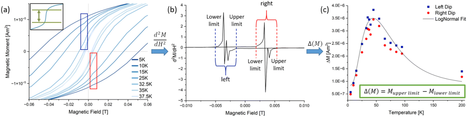 | ||
| Fig. 3 (a) A small-field section of the M(H) curves at different temperatures for the 4 mmol stearic acid thin film as an example. At ∼3 mT a “dip” (boxes) can be seen. The inset symbolizes the loss of magnetisation (ΔM) in a representative dip. (b) The 2nd derivative was calculated to determine the starting and end point of a dip. The differences of the magnetic moments were calculated and plotted over the temperature (c). The maximum of the log–normal fit in (c) was taken as the temperature with maximum dip height. | ||
To quantify the relevance of the dips in a comparative manner, the absolute values for ΔM for each sample were brought into relation to the respective saturation magnetisation (Table 2). For this the values of the left and right dip were taken into account to get an averaged value for both dips at the temperature with the highest change. From this table it can be seen that the spontaneous losses of magnetic moment at small fields are moderately high, but no huge differences are visible between the three ligand systems or ligand concentrations. However, this further confirms the presence of exchange coupling effects beyond normal magnetostatic interactions of ferromagnets. These spontaneous losses of magnetic moment indicate the presence of two different magnetic phases being present in the films.40 Since only particles from one synthesis each were used in the preparation of the films, all measured effects must have a different origin than the properties of the primary particle themselves.
| Ligands | 4 mmol | 12 mmol |
|---|---|---|
| Hexanoic acid/heptylamine | 14.9% | 14.0% |
| Decanoic acid/dodecylamine | 13.0% | 13.6% |
| Stearic acid/octadecylamine | 15.8% | 16.1% |
When plotting the blocking temperature (TB), the temperature at which the susceptibility change is the largest (dM/dH) and the temperature where the largest loss of magnetic moment was measured (d2M/dH2) over the length of the utilized ligands, it is remarkable how well these data points coincide in terms of their trends (Fig. 4). The exact temperatures may vary a bit between the methods, especially for the d2M/dH2 values, but the overall trend is the same, both for small and large ligand concentrations. Therefore, we suggest that the dipole interaction effect from particle interactions is directly responsible for the unusual order of the blocking temperatures in our thin films.
 | ||
| Fig. 4 Blocking temperatures of the nanoparticles in the thin films and in the capsules plotted over the chain length of the used ligand system. For the film formation and the capsulel preparation, the same batch of nanoparticles was used to enable a direct comparison. The inset shows a prepared sample for the capsule measurement. The darker left side of the cotton contains the particles. | ||
It has already been reported that purely ferromagnetic particles in an assembly can exhibit exchange bias effects due to a particular arrangement of the particles.22 In simulations a hexagonal packing produced purely ferromagnetic film properties, while cubic packing resulted in an antiferromagnetic coupling of the particles.20 The reason for this is that each particle has its own stray field, which then has an effect on neighbouring particles. In a hexagonal packing the stray field enhances the ferromagnetic characteristics of the particles while a cubic packing causes the stray field to induce an antiferromagnetic orientation of the particle spins. Due to the low temperatures, any movement of the particles can be neglected, as any additional ligand, which is not bound the surface of the particles, which could cause Brownian motion, is frozen and therefore solid.
To further prove that the tendencies in the unusual blocking temperatures originate from the exchange interactions of the self-assembled particles in the thin films and cannot stem from the properties of the primary particles themselves, another set of zfc/fc measurements was conducted. This time, the synthesised particles were not deposited as thin films, but instead, they were distributed on cotton to ensure that no ordering of the particles takes place. The cotton was then enclosed in a gelatine capsule for better handling (Fig. 5, inset). To inhibit any movement of the sample during measurement, the capsule was further filled with pure cotton. The blocking temperatures were then determined using eqn (4) (Table 3) and the results of both measurements (the blocking temperature obtained for the thin film and that obtained from the capsule) were plotted as a function of ligand length (Fig. 5).
 | ||
| Fig. 5 Trends of the magnetic characteristics of the thin films (as explained above and exemplified in Fig. 2 and 3) over the length of the ligands utilized for particle synthesis for the samples with a high (12 mmol, blue) and low ligand amount (4 mmol, red). | ||
| T B [K] | ||
|---|---|---|
| Ligands | 4 mmol | 12 mmol |
| Hexanoic acid/heptylamine | 9.2 | 7.8 |
| Decanoic acid/dodecylamine | 10.5 | 37.1 |
| Stearic acid/octadecylamine | 22.7 | 22.6 |
It is clearly visible that the blocking temperatures differ substantially, by up to 16.8 K for the 12 mmol DAc sample, and interestingly, the tendencies of the obtained values for the different ligand lengths are similar to the results in Fig. 4. In the films, the particles are densely packed and the particle–particle distances are mainly determined by the ligand length and concentration. In contrast, the particles in the cotton are distributed more widely and are randomly oriented in a more diluted fashion. It can thus be expected that this will lead to a sample resembling more the magnetic characteristics of the individual particles and neglecting any close-distance particle interactions. From the difference in the blocking temperatures, it can be concluded that the particle interactions get stronger with an increasing ligand length, which supports the argument that long ligands tend to induce a better self-assembly of the nanoparticles. Again, it can be observed that the 12 mmol SAc sample shows a low degree of influence on the blocking temperature, which can be correlated with a low degree of ordering. Due to the long ligand chains, the steric hindrance of the ligand is more important than for the shorter ligands. The long chains seem to severely impede a proper intercalation once there is a too high ligand density on the surface.41–43 This steric hindrance results in larger particle–particle distances, which then are too large for the stray field to induce significant magnetic interactions, similar to the effects we stated for the OAc samples.
In order to get a better insight into the degree of ordering of the prepared thin films, STEM measurements were done. Samples of all six ligand systems were prepared with the aim of generating monolayers or partial bilayers of particles to see if the particles tend to form highly ordered structures or rather remain in a randomly assembled state. In Fig. 6 the two samples with the highest differences in the blocking temperature are presented to give an exemplary overview of the self-assembly behaviour. On the left side the 12 mmol DAc particles (ΔTB = 16.8 K) show a high degree of ordering with very well visible bilayers (example in red box). The hexagonal structure of the bilayer is schematically shown in the upper right corner, where the blue spheres depict the bottom layer and the green spheres the top layer. On the right side, the 4 mmol HAc particles (ΔTB = 0 K) are shown. They also form bilayers, but these layers only consist of small areas with high structural order. Even though the monolayers show hexagonal packing, the bilayers remain much more randomly oriented compared to the 12 mmol DAc sample.
 | ||
| Fig. 6 STEM measurements of two samples to visualise the self-assembly in the films. To give the best comparison the sample with the highest ordering (12 mmol DAc) and the one with the lowest ordering (4 mmol HAc) are shown. In the red box a hexagonally ordered bilayer can be seen, which is illustrated for better visualisation as inset on the upper right corner. | ||
However, the samples prepared for STEM measurements exhibited mono- and bilayers only. In contrast, the thin films used for the magnetic measurements exhibited a thickness of 200–300 nm. In order to gain a more comprehensive understanding of the processes occurring in the thin films, an alternative characterisation method was employed that is able to detect any ordering in a film without destroying or interrupting it. The principal advantage of GISAXS measurements is their resolution while maintaining statistics, as they assess not only a limited section of the film but a larger area, thereby providing the relevant ensemble averages directly.44 GISAXS measurements were thus conducted to substantiate the presence of structural characteristics in the thin films that would lead to the observed exchange interaction effect (Fig. 7). The scattering curves demonstrate the presence of highly ordered structures that are larger than the nanoparticles themselves, indicated by the various peaks that are visible.45 It is important to note that these peaks are indicative of in-plane ordering of the particles. They correspond to the periodic spacing between adjacent particles or domains.
 | ||
| Fig. 7 Scattering curves derived from the GISAXS measurements, which were conducted on thin film samples for all particle systems. The left graph shows the films from the particles synthesised with 4 mmol ligand and the right graph shows the films formed from the particles synthesised with 12 mmol ligand. The visible peaks correspond to highly ordered structures within the films. | ||
In contrast, the estimation of particle size would be made from the low-q region (large scattering factors), independently of inter-particle arrangement. It is evident from both graphs that the observed peaks occur at different angles, which suggests the existence of multiple superlattices within a more randomly ordered film. The observed peaks mainly correspond to a 1D lamellar structure with lateral periodicity in the qy direction.46 It should be noted that the length values assigned to each peak do not represent the absolute structural size (average distance of scattering centres) of the ordered areas, but rather an average value calculated over a wider range. While all films reveal some degree of organisation, those prepared with the 4 mmol ligand particles (Fig. 7, left) exhibit higher intensities of the diffraction signals and correspond to larger structures than those prepared with the 12 mmol ligand particles (Fig. 7, right). These findings are consistent with the conclusions of the measurements discussed above, which indicated that an excess of ligand, particularly for the longer molecules, impeded the self-assembly process due to steric hindrance. Although there are some discrepancies between the results of the different measurements – for instance, the 4 mmol HAc sample exhibited no distinct ordering in the STEM measurement but displayed the most intense peak in the GISAXS measurement – the overall principle of how the ligands affect the self-assembly behaviour of the particles in the thin films remains consistent. It is also plausible that these disparities can be ascribed to the enhanced bulk sensitivity of GISAXS, given that STEM is only able to access bilayers, which are more susceptible to surface effects.
The presence of highly ordered areas in the STEM and GISAXS measurements further confirms the theory that the unusual magnetic features of the thin films originate from their three-dimensional internal structure and not the properties of the individual particles. We already discussed that the spontaneous loss of magnetisation at low fields can be induced by the presence of two different magnetic phases in the films that interact with each other in a ferrimagnetic-like manner. One phase is thereby represented by the hexagonally ordered areas that extend throughout the layer, the other one by the cubically ordered or completely disordered areas (Fig. 8(a)). In the ordered areas, the hexagonal packing of the particles results in enhanced ferromagnetic characteristics, whereas the unordered areas show no effect on the overall magnetic moment. In a cubic packing scenario, the ordered areas show diminished ferromagnetic features due to unfavourable stray field effects, which cancel parts of the overall measured magnetic moment. If two of these phases are present in a film they influence each other and, therefore, show enhanced dipole interactions in the magnetic measurements that resemble those of ferrimagnetic materials (Fig. 8(b)).40 Since the thin films were prepared via drop-casting and the formation of the different phases depends highly on the self-assembly process during the drying step, a more realistic behaviour is shown in Fig. 8(c). Here the hexagonally ordered superlattice structure is represented by the large red arrows and the unordered areas in the film volume are symbolised by the more randomly oriented smaller spheres (the color indicates the magnetisation direction). At small fields the majority of the superparamagnetic nanoparticles is oriented along the external field. The overall magnetic characteristic of the film in (c) is dominated by the ordered, ferromagnetic 3D-assemblies. The unordered areas have no huge influence on the overall magnetic moment generated by the ordered superlattices, but there are also small areas where cubically packed particles show a negative effect on the total magnetisation, since part of the magnetic moments cancel each other out (indicated by the bright blue arrows). This situation can be seen in the spontaneous loss of magnetic moment in the M(H) measurements (Fig. 2(a)). The effective magnetic characteristics of the films are therefore caused by a mixture of stray-field effects and dipole interactions between two different superlattice phases in the thin films, both being a consequence of the self-assembly of the nanoparticles.
 | ||
| Fig. 8 Schematic illustration of the two ordered magnetic phases present at low external field. (a) Assembly formation of the particles influences the overall magnetic moment. A hexagonal packing (red, high order) enhances the overall magnetic moment, a cubic formation (blue, low order) diminishes the overall magnetic moment. The stray fields influencing the neighbouring particles are shown in green. (b) Ideal presence of the two interacting phases in the thin film (red = assemblies with enhanced ferromagnetism, blue = assemblies with dimished ferromagnetism). (c) More realistic depiction of the phases present in the films. The colours indicate the orientation of the magnetic particles (indicated by the colour wheel). | ||
Through the choice of three different ligands with different chain lengths, the self-assembly process of the particles can be influenced, since the ligands act as stabilizers for an ordered arrangement. On the one hand, longer ligands have a more favourable effect on the ordering, since the van der Waals forces between the carbon chains are strong enough to have a major influence on the self-assembly process.47 On the other hand, the use of the optimum amount of ligand is also very important, as too much ligand, either on the particle surface or as excess in the sample, will lead to steric hindrance effects and, therefore, interfere with the self-assembly process, as can be seen for the 12 mmol SAc particles (Fig. 7).48,49 A reduction in the amount of ligand on the surface enhances the self-assembly process, as the ligands now have enough space to properly intercalate into each other.50,51 Due to larger van der Waals forces stabilising the intercalation, the longer ligands show a better intercalation, if enough space is available, and a self-assembly results in a larger superlattices of hexagonally packed particles. This effect is already indicated in the initial determination of the blocking temperatures (Table 1). The shorter ligands appear to exhibit a higher critical ligand threshold with regard to steric hindrance effects than the longer ligands. This resulted in an increase in the blocking temperature for the HAc and DAc particles and a decrease for the SAc and OAc particles with increasing ligand concentration. The stereochemistry of oleic acid is important, as the double bond between C9 and C10 forces the alkyl chain into a bent form, significantly reducing its ability to intercalate with other oleic acid molecules.43 Therefore, the large van der Waals forces enable a good ordering of the particles, as can be seen in Fig. 7, but the double bond causes an enlarged interparticle distance, so that the stray fields of the particles are no longer influencing the neighbouring particles, reducing the magnetic exchange interactions.
Conclusions
In conclusion, the present investigation has demonstrated a clear dependence of the magnetic characteristics of SPION-based thin films on their internal three-dimensional structural characteristics. It was observed that there was an increase in blocking temperature with longer ligand lengths and thus higher ordering, and significant changes in the magnetization versus magnetic field (M(H)) curves, including noticeable “dips” that indicate the spontaneous cancellation of magnetic moments when reaching a defined temperature. These dips are considered valuable indicators of the exchange interactions among the nanoparticles. To explain this phenomenon, we introduced a hypothesis about the existence of hexagonal, cubic and unordered superlattice phases within the films, each contributing differently to the overall magnetic properties. Specifically, it was hypothesised that hexagonal packing of the nanoparticles in the films would enhance their overall magnetic moment, while a cubic packing would result in a diminished overall magnetic moment, due to the partial cancellation of the magnetic moments.The selected ligand system for the self-assembly process has been demonstrated to exert a substantial influence on the magnetic behaviour of the thin films. Our findings suggest that longer ligands promote the self-assembly process, thereby facilitating the formation of hexagonally ordered structures. Specifically, medium-length (C10) ligands produced the most favourable outcomes, stabilising the hexagonal packing configuration while preserving minimal inter-particle distances. This optimal arrangement enhances interfacial interactions between the nanoparticles, ultimately leading to favourable magnetic interactions, as evidenced by the significant shift in blocking temperature for the thin films consisting of DAc particles. However, it is crucial to maintain optimal ligand concentrations, as exceeding these levels can lead to steric hindrance effects and increased particle distances. The occurrence of this phenomenon can result in a reduction of exchange interactions, despite the maintenance of a functional self-assembly process.
In summary, a thorough understanding and control of the interplay between magnetic characteristics, structural arrangements, and self-assembly processes are essential for optimizing the performance of particle-based magnetic thin films in various applications. The detailed analysis of temperature-dependent magnetisation curves enables a quantitative determination of magnetic coupling effects and, in combination with integral analysis methods such as GISAXS, also of structural ordering in magnetic nanoparticle-based thin films. For future research, in order to fully clarify the underlying ordering and coupling mechanisms within the self-assembled structures, there is a need for a more in-depth analysis of thinner films with GISAXS measurements to improve in-plane ordering and lattice visibility.
Author contributions
The authors of this article made the following contributions: conceptualization: M.G., S.O.; investigation: M.G., G.Y.; formal analysis: M.G., G.Y.; resources: H.N., T.V., G.G.; supervision: G.G.; visualization: M.G., G.Y.; writing – original draft: M.G.; writing – review & editing: S.O., H.N., T.V., G.G.; funding acquisition: G.G.Data availability
The data supporting this article have been included as part of the ESI.†Conflicts of interest
There are no conflicts to declare.Acknowledgements
M. Görke acknowledges funding from the Hannover School of Nanotechnology (HSN). The authors also acknowledge the use of FIB-SEM for performing STEM measurements at the Laboratory for Emerging Nanometrology (LENA) funded by the DFG under grant INST 188/452-1 FUGG.References
- E. L. Rösch, J. Zhong, A. Lak, Z. Liu, M. Etzkorn, M. Schilling, F. Ludwig, T. Viereck and B. Lalkens, Biosens. Bioelectron., 2021, 192, 113536 CrossRef PubMed.
- S. Aberdeen, E. Cali, L. Vandeperre and M. P. Ryan, J. Mater. Chem. A, 2023, 11, 15855–15867 RSC.
- S. Furrer, P. Ebermann, M. A. Lantz, H. Rothuizen, W. Haeberle, G. Cherubini, R. D. Cideciyan, S. Tsujimoto, Y. Sawayashiki, N. Imaoka, Y. Murata, T. Ueyama, Y. Akano, T. Kaneko, H. Suzuki, M. Shirata, K. Naoi, T. Koike and H. Doshita, IEEE Trans. Magn., 2021, 57, 1–11 Search PubMed.
- C. Papusoi, T. Le, P.-O. Jubert, D. Oswald, B. Ozdol, D. Tripathy, P. Dorsey and M. Desai, J. Magn. Magn. Mater., 2019, 483, 249–265 CrossRef CAS.
- J. Tachibana, H. Kobayashi, T. Sai, S. Kodama, T. Aizawa, A. Yamaguchi and S. Saito, IEEE Trans. Magn., 2023, 59, 1–5 Search PubMed.
- E. E. Ateia, M. A. Ateia and M. M. Arman, J. Mater. Sci.: Mater. Electron., 2022, 33, 8958–8969 CrossRef CAS.
- W. M. Daoush, J. Nanomed. Res., 2017, 5(3), 00118 Search PubMed.
- C. Sandoval, INSIC Technology Roadmap 2019 – SM, 2019 Search PubMed.
- V. Maurer, S. Altin, D. Ag Seleci, A. Zarinwall, B. Temel, P. M. Vogt, S. Strauß, F. Stahl, T. Scheper, V. Bucan and G. Garnweitner, Pharmaceutics, 2021, 13, 394 CrossRef CAS PubMed.
- G. F. Goya, T. S. Berquó, F. C. Fonseca and M. P. Morales, J. Appl. Phys., 2003, 94, 3520–3528 CrossRef CAS.
- Y. Hadadian, H. Masoomi, A. Dinari, C. Ryu, S. Hwang, S. Kim, B. K. Cho, J. Y. Lee and J. Yoon, ACS Omega, 2022, 7, 15996–16012 CrossRef CAS PubMed.
- F. Fabris, K.-H. Tu, C. A. Ross and W. C. Nunes, J. Appl. Phys., 2019, 126, 173905 CrossRef.
- M. Görke, S. Okeil, D. Menzel, B. Semenenko and G. Garnweitner, Part. Part. Syst. Charact., 2024, 41, 2400059 CrossRef.
- H. Zargartalebi, S. H. Hejazi and A. Sanati-Nezhad, Nat. Commun., 2022, 13, 3085 CrossRef CAS PubMed.
- C. Preger, M. Josefsson, R. Westerström and M. E. Messing, Nanotechnology, 2021, 32, 195603 CrossRef CAS PubMed.
- E. Myrovali, K. Papadopoulos, I. Iglesias, M. Spasova, M. Farle, U. Wiedwald and M. Angelakeris, ACS Appl. Mater. Interfaces, 2021, 13, 21602–21612 CrossRef CAS PubMed.
- Y. Zhang, L. Zhao, S. Li, M. Liu, M. Feng and H. Li, Appl. Phys. A, 2018, 124, 159 CrossRef.
- H. Kachkachi, arXiv:cond-mat/0611677, 2018, DOI:10.48550/arXiv.cond-mat/0611677.
- T. Preller, S. Knickmeier, D. Menzel, B. Temel and G. Garnweitner, Langmuir, 2020, 36, 2093–2101 CrossRef CAS PubMed.
- S. D. Slöetjes, H. H. Urdahl, J. K. Grepstad and E. Folven, AIP Adv., 2017, 7, 056325 CrossRef.
- E. Wetterskog, A. Klapper, S. Disch, E. Josten, R. P. Hermann, U. Rücker, T. Brückel, L. Bergström and G. Salazar-Alvarez, Nanoscale, 2016, 8, 15571–15580 RSC.
- G. Muscas, G. Concas, S. Laureti, A. M. Testa, R. Mathieu, J. A. de Toro, C. Cannas, A. Musinu, M. A. Novak, C. Sangregorio, S. S. Lee and D. Peddis, Phys. Chem. Chem. Phys., 2018, 20, 28634–28643 RSC.
- W. Cao, S. Xia, X. Jiang, M. Appold, M. Opel, M. Plank, R. Schaffrinna, L. P. Kreuzer, S. Yin, M. Gallei, M. Schwartzkopf, S. V. Roth and P. Müller-Buschbaum, ACS Appl. Mater. Interfaces, 2020, 12, 7557–7564 CrossRef CAS PubMed.
- L. L. Félix, M. A. Rodriguez Martínez, D. G. Pacheco Salazar and J. A. Huamani Coaquira, RSC Adv., 2020, 10, 41807–41815 RSC.
- J. A. de Toro, P. S. Normile, S. S. Lee, D. Salazar, J. L. Cheong, P. Muñiz, J. M. Riveiro, M. Hillenkamp, F. Tournus, A. Tamion and P. Nordblad, J. Phys. Chem. C, 2013, 117, 10213–10219 CrossRef CAS.
- I. Morales, A. Koch, C. Wesemann, R. T. Graf and N. C. Bigall, Nanoscale, 2025, 17, 5993–6003 RSC.
- H. Mamiya, I. Furukawa, J. L. C. Huaman, K. Suzuki, H. Miyamura and B. Jeyadevan, J. Phys. Commun., 2021, 5, 45003 CrossRef CAS.
- J. Hesselbach, A.-C. Böttcher, I. Kampen, G. Garnweitner, C. Schilde and A. Kwade, Coatings, 2018, 8, 156 CrossRef.
- M. S. Seehra and K. L. Pisane, J. Phys. Chem. Solids, 2016, 93, 79–81 CrossRef CAS.
- M. Knobel, W. C. Nunes, H. Winnischofer, T. Rocha, L. M. Socolovsky, C. L. Mayorga and D. Zanchet, J. Non-Cryst. Solids, 2007, 353, 743–747 CrossRef CAS.
- F. L. Durhuus, M. Beleggia and C. Frandsen, Phys. Rev. B, 2024, 109, 054421 CrossRef CAS.
- W. F. Brown, Phys. Rev., 1963, 130, 1677–1686 CrossRef.
- J. Rackham, B. Pratt, D. Griner, D. Smith, Y. Cai, R. G. Harrison, A. Reid, J. Kortright, M. K. Transtrum and K. Chesnel, Phys. Rev. B, 2023, 108, 104415 CrossRef CAS.
- S. Bedanta and W. Kleemann, J. Phys. D: Appl. Phys., 2009, 42, 13001 CrossRef.
- D. Kim, S. Park, J. Lee, J. Yoon, S. Joo, T. Kim, K.-J. Min, S.-Y. Park, C. Kim, K.-W. Moon, C. Lee, J. Hong and C. Hwang, Nanotechnology, 2019, 30, 245701 CrossRef CAS PubMed.
- T. Magno de Lima Alves, B. F. Amorim, M. A. Morales Torres, C. G. Bezerra, S. Nóbrega de Medeiros, P. L. Gastelois, L. E. Fernandez Outon and W. Augusto de Almeida Macedo, RSC Adv., 2017, 7, 22187–22196 RSC.
- C. Parmar, R. Verma, S. S. Modak, F. Mazaleyrat, T. Tatarchuk and S. N. Kane, Mol. Cryst. Liq. Cryst., 2023, 767, 115–125 CrossRef CAS.
- B. Rivas-Murias, M. Testa-Anta, A. S. Skorikov, M. Comesaña-Hermo, S. Bals and V. Salgueiriño, Nano Lett., 2023, 23, 1688–1695 CrossRef CAS PubMed.
- P. Swekis, J. Gayles, D. Kriegner, G. H. Fecher, Y. Sun, S. T. B. Goennenwein, C. Felser and A. Markou, ACS Appl. Electron. Mater., 2021, 3, 1323–1333 CrossRef CAS.
- A. Aharoni, Introduction to the Theory of Ferromagnetism, Clarendon, Oxford, 2nd edn, 2000 Search PubMed.
- Y. Eygeris, Q. Wang, M. Görke, M. Grünwald and I. Zharov, ACS Appl. Mater. Interfaces, 2023, 15, 29384–29395 CrossRef CAS PubMed.
- Z. Fan and M. Gruenwald, ChemRxiv, 2019, 1, DOI:10.26434/chemrxiv.9178037.v1.
- K. Bian, R. Li and H. Fan, Chem. Mater., 2018, 30, 6788–6793 CrossRef CAS.
- E. Josten, E. Wetterskog, A. Glavic, P. Boesecke, A. Feoktystov, E. Brauweiler-Reuters, U. Rücker, G. Salazar-Alvarez, T. Brückel and L. Bergström, Sci. Rep., 2017, 7, 2802 CrossRef PubMed.
- K. Vegso, P. Siffalovic, M. Benkovicova, M. Jergel, S. Luby, E. Majkova, I. Capek, T. Kocsis, J. Perlich and S. V. Roth, Nanotechnology, 2012, 23, 45704 CrossRef CAS PubMed.
- B. Weidinger, G. Yang, N. von Coelln, H. Nirschl, I. Wacker, P. Tegeder, R. R. Schröder and E. Blasco, Adv. Sci., 2023, 10, e2302756 CrossRef PubMed.
- Z. Fan and M. Grünwald, J. Am. Chem. Soc., 2019, 141, 1980–1988 CrossRef CAS PubMed.
- C. Waltmann, N. Horst and A. Travesset, ACS Nano, 2017, 11, 11273–11282 CrossRef CAS PubMed.
- M. C. Weidman, Q. Nguyen, D.-M. Smilgies and W. A. Tisdale, Chem. Mater., 2018, 30, 807–816 CrossRef CAS.
- R. T. Graf, K. Tran, M. Rosebrock, H. Borg, J. Schlenkrich, F. Lübkemann-Warwas, F. Renz, D. Dorfs and N. C. Bigall, Adv. Mater. Interfaces, 2023, 10, 2300408 CrossRef CAS.
- R. T. Graf, A. Schlosser, D. Zámbó, J. Schlenkrich, P. Rusch, A. Chatterjee, H. Pfnür and N. C. Bigall, Adv. Funct. Mater., 2022, 32, 2112621 CrossRef CAS.
Footnote |
| † Electronic supplementary information (ESI) available. See DOI: https://doi.org/10.1039/d5nr00973a |
| This journal is © The Royal Society of Chemistry 2025 |