
 Open Access Article
 This Open Access Article is licensed under a
 Creative Commons Attribution 3.0 Unported Licence
70 wt% SiO2-loaded flexible PVDF quasi-solid-state electrolyte membrane for lithium oxygen batteries†
A-Qiang
Wu‡
a,
Mingxing
Wang‡
a,
Xiangqun
Zhuge
 a,
Tong
Liu
a,
Kun
Luo
*a,
Zhihong
Luo
b,
Mian
Zhong
*c,
Yurong
Ren
a,
Hanhui
Lei
d,
Zhanhui
Yuan
e and
Terence Xiaoteng
Liu
*d
a,
Tong
Liu
a,
Kun
Luo
*a,
Zhihong
Luo
b,
Mian
Zhong
*c,
Yurong
Ren
a,
Hanhui
Lei
d,
Zhanhui
Yuan
e and
Terence Xiaoteng
Liu
*d
aJiangsu Province Engineering Research Centre of Intelligent Manufacturing Technology for the New Energy Vehicle Power Battery, School of Materials Science and Engineering, Changzhou University, Changzhou 213164, P R China. E-mail: luokun@cczu.edu.cn
bCollege of Materials Science and Engineering, Guilin University of Technology, Guilin 541004, P R China
cCollege of Aviation Electronics and Electrical, Civil Aviation Flight University of China, Deyang 618307, P R China. E-mail: mianzhong@cafuc.edu.cn
dDepartment of Mechanical and Construction Engineering, Faculty of Engineering and Environment, Northumbria University, Newcastle upon Tyne, UK. E-mail: terence.liu@northumbria.ac.uk
eCollege of Materials and Engineering, Fujian Agriculture and Forestry University, Fuzhou 350108, China
First published on 14th May 2025
Abstract
Unique flexible PVDF-based quasi-solid-state electrolytes (QSSEs) with PMMA-modified nanosilica additives were successfully prepared to enhance the safety, energy density, and cycling stability of lithium oxygen batteries (LOBs). With 70 wt% of nanosilica additive (SP70), the membrane exhibited remarkable Li+ conductivity, electrolyte uptake and mechanical strength, hindering the shuttling of anions (I− and I3−) and any harmful species, without any decline in physical flexibility. Iodine was added to enhance the kinetics of the oxygen evolution reaction (OER) and expedite the decomposition of the discharge product, Li2O2. Furthermore, the cycle life of iodine-assisted LOBs was extended from 103 cycles with pristine PVDF to 402 cycles with SP70 at 1.0 A g−1 and 1000 mA h g−1 charge/discharge testing conditions. The full discharge capacity was improved to 45![[thin space (1/6-em)]](https://www.rsc.org/images/entities/char_2009.gif) 336 mA h g−1, which was twice that of the LOB with the PVDF-only membrane.
336 mA h g−1, which was twice that of the LOB with the PVDF-only membrane.
1. Introduction
In recent years, conventional lithium-ion batteries (LIBs) have been confronting with a “mileage anxiety” owing to their insufficient energy density (200–300 W h kg−1) for electric vehicles.1,2 Thus, other lithium metal batteries, such as lithium–sulfur (ca. 2500 W h kg−1) and lithium–oxygen batteries (LOBs, ca. 3500 W h kg−1), have received enormous attention because of their high energy densities,3–6 where the latter are envisaged as ultimate energy storage devices. However, various challenges remain for the practical applications of LOBs, such as the sluggish kinetics of oxygen reduction reaction (ORR) and oxygen evolution reaction (OER), accumulation of discharge products, quick lithium metal consumption and degradation of electrolytes.7–12In particular, the LOB discharge product lithium peroxide (Li2O2), which is formed by the ORR at the electrolyte/cathode interface, is insoluble and insulative. Furthermore, the electrochemical decomposition of Li2O2 in the OER is dependent on the electron transfer at both the electrolyte/cathode and Li2O2/cathode interfaces, making the complete decomposition of Li2O2 difficult during recharging and leading to the accumulation of discharge products or even passivation of the cathode. ORR or OER catalysts can prompt the kinetics in short term but result in full coating with Li2O2. Therefore, soluble redox mediators (RMs) are selected to effectively lower the ORR and OER overpotentials, and several RMs have been reported to be used in LOBs, including tetrathiafulvalene (TTF), iron phthalocyanine (FePc), 2,2,6,6,-tetramethylpiperidinyl-oxyl (TEMPO), and dimethylphenazine (DMPZ).13–16 LiI has been the most extensively studied, and iodide can be converted according to the two redox reactions in DMSO, namely, I−/I3− and I3−/I2,17,18 where both I2 and I3− generated in the OER process (see eqn (1) and (2)) can react with Li2O2 (eqn (3) and (4)) as follows:
| 3I− → I3− + 2e−, | (1) |
| 2I3− → 3I2 + 2e−, | (2) |
| I3− + Li2O2 → 2Li+ + O2 + 3I−, | (3) |
| 3I2 + Li2O2 → 2Li+ + O2 + 2I3−. | (4) |
I3− is soluble and can diffuse across the separator to corrode the Li anode. Therefore, constructing an impermeable separator with high Li+ ionic conductivity and very low shuttling of iodide ions is desired to diminish the detrimental interplay between the cathode and anode processes in LOBs.
As a promising candidate for solid electrolytes, composite polymer electrolytes combine the advantages of high ionic conductivity, enhanced elastic modulus, sufficient flexibility, adaptability to volume changes and interface compatibility with electrodes owing to the interaction between inorganic fillers and the polymer matrix, which endows LOBs and other lithium metal batteries with superior electrochemical properties and safety.19,20 The introduction of inorganic fillers can reduce the crystallinity of the polymer, promote the dissociation of lithium salts, and establish new ion conduction channels. TiO2, Al2O3, SiO2 and other inert materials have been widely used owing to their easy synthesis, controllable particle size and excellent chemical stability.21–23 Studies have shown that the introduction of ceramic nanoparticles can increase the Li+ concentration at the interface; therefore, fillers with Lewis acidic surfaces are more favorable to Li+.24–28
For example, SiO2 nanoparticles with Lewis acidic surfaces can interact with anions,29 and the newly established hydrogen bonds make the fillers become crosslinking centers of polymers and anions, further disrupting the crystallinity of the polymer matrix.26,30 Moreover, the large-scale fabrication of SiO2 nanoparticles is mature and cost-effective, and high-loading of SiO2 fillers allows the polymer nanocomposites to approach the performance of inorganic solid electrolyte films, such as Li7La3Zr2O12,31 Li10GeP2S12,32 Li1.3Al0.3Ti1.7(PO4)333 and Li3YCl6,34 which are known for their high elastic modulus and superior ionic conductivity, but face the challenges of inherent brittleness, poor interface contact with electrodes, and high cost. Cui et al. developed a silica-aerogel reinforced composite polymer electrolyte comprising a continuous SiO2-aerogel network, which resulted in a notable enhancement in the mechanical properties and ionic conductivity of the electrolyte.35 Chen et al. employed an interfacial layer constituted by ionic liquid adsorption on the surface of mesoporous silica to attenuate the anionic binding of Li+ and augment the conductivity of the solid electrolyte to 1.4 mS cm−1.36 Yin et al. fabricated a series of SiO2-reinforced PVDF-HFP quasi-solid-electrolytes (QSSEs) and found that there was an apparent increase in Li+ conductivity with the content of SiO2, and the highest conductivity (10−3 S cm−1) was assigned to the QSSE with 80 wt% SiO2 because the dominant Li+ conductance mechanism changes from the bulk transport mechanism to the interfacial transport mechanism.26
Inspired by these studies, we systematically investigated the effect of high loading fillers on the performance of the SiO2/PVDF composites and further enhanced their flexibility by the surface modification of SiO2 with PMMA coating. The optimized composite membrane (SP70, 70 wt% SiO2) exhibited a high ionic conductivity of 1.48 × 10⁻³ S cm−1, with a superior Young's modulus (12 GPa on average) and flexibility. SP70 also had a high electrolyte uptake and could serve as a QSSE for LOBs, which offered uniform Li+ and inhibited Li dendrite growth, and strengthened the PVDF matrix from chemical corrosion by oxidative intermediates in battery reactions. More importantly, the results demonstrated that the SP70 membrane could effectively hinder the transfer of both I− and I3− across the membrane, and its ion-selective nature has not been reported to the best of our knowledge. Consequently, the lifespan of iodine-assisted LOBs was significantly elongated from 103 cycles with pristine PVDF to 402 cycles with SP70 at 1.0 A g−1 and 1000 mA h g−1, and the full discharge capacity was approximately doubled from 24277 mA h g−1 to 45336 mA h g−1. The excellent performance and cost-effectiveness of the high loading SiO2-reinforced nanocomposites provide a new design strategy for QSSEs for the practical application of LOBs.
2. Experimental
2.1 Materials and chemicals
Tetraethyl orthosilicate (TEOS, 98%), ammonium hydroxide (28%), 3-(trimethoxymethylsilyl)propyl methacrylate (MPS, 98%), sodium dodecyl sulfate (SDS, 99%), potassium persulfate (KPS), oxalic acid (≥97%), ethanol (≥ 99.7%), N,N-dimethylformamide (DMF, ≥99.5%) and methyl methacrylate (MMA) were bought from Sinopharm Chemical Reagent Co., Ltd, China. PVDF (Mw = 600000) was purchased from Arkema. Multi-walled carbon nanotubes (MWCNTs, ≥98%), dimethyl sulfoxide (DMSO, 99.9%), propylene carbonate (PC, 99.7%), lithium perchlorate (LiClO4, ≥99.99%), lithium iodide (LiI, 99.9%), and molecular sieves (4 Å) were bought from Sigma-Aldrich. Lithium flake (d = 14 mm) was purchased from Tianjin Zhongneng Lithium Co., Ltd. Glass fiber separators (GF, d = 18 mm, Whatman) were used as received.
LiClO4 and LiI were dried in a vacuum oven at 120 °C for more than 12 h and then used to prepare 1.0 mol L−1 LiClO4/DMSO and LiI/LiClO4/DMSO (with 1.0 mol L−1 LiClO4 and 0.05 mol L−1 LiI) electrolytes. Activated molecular sieves were added to remove trace water from the electrolytes for one week before use. The lithium flake was immersed in 0.1 mol L−1 LiClO4/PC solution for more than 3 days.
2.2 Pre-treatment of SiO2 nanoparticles
SiO2 nanoparticles were prepared by applying the modified Stober method,37 with details in the ESI.† MPS and SiO2 were dispersed into a mixed solution of ethanol and water with a volume ratio of 3:1. The pH was adjusted to 3.5–4 with 0.1 M oxalic acid, stirred in a water bath at 70 °C for 7 h, and the MPS-modified SiO2 nanoparticles were obtained after centrifugal washing with ethanol and deionized water.24
SiO2-PMMA nanoparticles were prepared by emulsion polymerization according to previous studies.38,39 MPS-modified SiO2, MMA, SDS and isopropanol were added in sequence into deionized water, which were pre-emulsified and degassed by N2 for 30 min, followed by the initiation of polymerization by the addition of KPS solution at 75 °C for 8 h. The product was repeatedly centrifugally washed with deionized water and then dried at 70 °C for 24 h, resulting in the PMMA-modified SiO2 nanoparticles, denoted as SiO2-PMMA.
2.3 Preparation of SiO2/PVDF composite membranes
SiO2-PMMA and PVDF were dissolved in DMF under ultrasonic stirring at the weight ratios of 5:5, 6:4, 7:3 and 8:2 After degassing, the solution was poured onto a glass plate, and the thickness of the film was controlled to be 70 ± 10 μm using a home-made film scraper and finally kept at 40 °C overnight in a vacuum oven, leading to the SiO2/PVDF composite membranes, which were named SP50, SP60, SP70 and SP80 according to the SiO2 ratios in the composites, respectively. As a reference, a pristine PVDF membrane was fabricated for comparison.
2.4 Characterizations
Morphological and structural analyses were performed by applying a scanning electron microscope (SEM, Phenom LE, Thermo Fisher Scientific). A high-resolution 3D X-ray microscope (Zeiss Xradia 510 Versa) was applied to 3D imaging of samples. A contact angle measuring instrument (DSA100S, KRUSS) was used to measure the wettability of the membranes. X-ray photoelectron spectroscopy (XPS, Thermo ESCALAB 250XI), X-ray diffractometer (XRD, D/max 250 PC, Rigaku), Raman spectrometer (532 nm, DXR2, Thermo), FT-IR spectrometer (FTIR, Thermo Scientific Nicolet iS5) and thermal analyzer (TG-DSC, PE STA8000) were also used to characterize the samples. The Young's modulus of the membranes was measured by Atomic Force Microscopy (AFM) (Bruker Dimension ICON). An electrochemical workstation (CHI660E, Shanghai Morning China Instrument Co., Ltd) was used to carry out EIS analysis, where the AC amplitude was 5 mV, and the frequency varied in the range of 0.1 Hz–106 Hz. Detailed electrochemical analysis and LOB testing are demonstrated in the ESI.†3. Results and discussion
3.1 Characterizations of the SiO2/PVDF composite membranes
Fig. 1a schematically illustrates the synthesis of SiO2/PVDF QSSEs with a high loading of SiO2 nanoparticles. Fig. 1b shows the morphology of SiO2 nanoparticles prepared using Stober's method (with details in ESI†). The as-synthesized SiO2 nanoparticles are spherical with uniform particle sizes, which are measured as 310 ± 10 nm (N = 100), as shown in Fig. S1a.†Fig. 1c illustrates the synthesis of SiO2-PMMA nanoparticles by MPS modification and MMA grafting, where small dots appear on the surface of SiO2 nanoparticles. | ||
| Fig. 1 Synthesis of SiO2-PMMA/PVDF QSSE (a); SEM images of pristine SiO2 (b) and SiO2-PMMA (c); SEM images of the SP70 QSSE surface at low (d ) (inset: cross-section) and high magnifications (e); AFM topography and Young's modulus (f) and the flexibility of the SP70 QSSE (g). | ||
FT-IR analysis of the SiO2-PMMA nanoparticles in Fig. S1b† shows that absorption peaks appear at 1100 cm−1 and 800 cm−1, corresponding to the asymmetric and symmetric stretching vibrations of Si–O–Si, respectively.38 The peak present at 1730 cm−1 corresponds to the C![[double bond, length as m-dash]](https://www.rsc.org/images/entities/char_e001.gif) O bond of PMMA, and the peaks between 750 and 1350 cm−1 can be attributed to the stretching vibrations of the C–O–C bond.24 The broad peak at 3437 cm−1 indicates that, even though PMMA is grafted onto SiO2, hydroxyl groups are still present on its surface, which can act as Lewis acids to promote the dissociation of lithium salts and provide more free Li+.38,39 Fig. S1c† illustrates that the weight loss of the SiO2-PMMA nanoparticles near 100 °C is due to the evaporation of adsorbed water, and the rapid weight loss at 300–400 °C is caused by the dehydrogenation of PMMA. Thereafter, the surface PMMA decomposed, and at 800 °C, only SiO2 remained, occupying ca. 75 wt% of the overall weight. Fig. S1d† illustrates the XRD analysis, which exhibits little structural change between the as-synthesized SiO2 and SiO2-PMMA nanoparticles.
O bond of PMMA, and the peaks between 750 and 1350 cm−1 can be attributed to the stretching vibrations of the C–O–C bond.24 The broad peak at 3437 cm−1 indicates that, even though PMMA is grafted onto SiO2, hydroxyl groups are still present on its surface, which can act as Lewis acids to promote the dissociation of lithium salts and provide more free Li+.38,39 Fig. S1c† illustrates that the weight loss of the SiO2-PMMA nanoparticles near 100 °C is due to the evaporation of adsorbed water, and the rapid weight loss at 300–400 °C is caused by the dehydrogenation of PMMA. Thereafter, the surface PMMA decomposed, and at 800 °C, only SiO2 remained, occupying ca. 75 wt% of the overall weight. Fig. S1d† illustrates the XRD analysis, which exhibits little structural change between the as-synthesized SiO2 and SiO2-PMMA nanoparticles.
High filler loading results in apparent structural changes to PVDF-based nanocomposites. Fig. 1d demonstrates the surface and cross-section (inset) of the SP70 membrane, where the SiO2-PMMA nanoparticles are close-packed to each other with a thickness of approximately 75 μm, and the PVDF resembles a binder rather than a matrix as some PVDF even appear in the form of filaments (Fig. 1e), which implies that the inside SiO2-PMMA nanoparticles form a continuous 3D framework across the SP70 membrane available for ionic conductance based on the interfacial transfer mechanism. Furthermore, Fig. S2a† depicts that the incorporation of SiO2-PMMA nanoparticles effectively reduces the crystallinity of PVDF, which also favors the ionic conductance of PVDF.27 Fig. S2b† illustrates the FTIR analyses of the PVDF and SP70 QSSEs. For the PVDF QSSE, the bending vibration peaks of –CF2, stretching vibration peaks of –CF2 and bending vibration peaks of –CH2 are observed at 879, 1172 and 1405 cm−1, respectively.40 For the SP70 QSSE, an additional bending vibration of Si–O and antisymmetric stretching vibration of Si–O–Si appear at 442 and 1050 cm−1, respectively, confirming the combination of SiO2 nanoparticles and PVDF.23
It is worth mentioning that owing to the high filling of SiO2 nanoparticles, the average Young's modulus increases rapidly from less than 1 GPa for PVDF to as high as 12 GPa for SP70 according to the AFM analysis depicted in Fig. 1f, which meets the demand of resisting the disordered production of Li dendrites.41Fig. 1g further displays that the SP70 exhibits remarkable flexibility, which is very difficult for polymer composites with high loading of inorganic nanofiller. As a reference, the SP80 membrane with the SiO2-PMMA content of 80 wt% resulted in the brittleness of the SiO2/PVDF composite membrane (Fig. S3†). Fig. S4a† shows that the SEM image of the pristine SiO2 nanoparticles is a reinforced PVDF nanocomposite with a content of 50 wt%, where the SiO2 nanoparticles appear randomly aggregated and are not compatible with the PVDF. Consequently, the membrane is also brittle and easy to break, as shown in Fig. S4b,† showing the necessity of PMMA surface grafting of SiO2 nanoparticles.
To visualize the 3D morphology inside the sample, X-ray computed tomography (XCT) was used to scan the SP70 QSSE.42Fig. 2a displays the cross-section images of the SP70 QSSE, where the internal SiO2 nanoparticles were uniformly distributed and densely stacked in the composite, confirming the existence of a continuous SiO2-nanoparticle network in the membrane available for ionic conductance. The well-incorporated SiO2-PMMA nanoparticles significantly improves the thermal stability of the SP70 compared with the PVDF membrane, where the SP70 membrane exhibits little change when it was heated to 200 °C for 1 h, as shown in Fig. S5,† while the pristine PVDF membrane significantly shrinks, highlighting the stability and reliability of the SP70 membrane as a candidate QSSE for LOBs.
 | ||
| Fig. 2 XCT analysis of the SP70 QSSE (a); the ratios of electrolyte uptake (b) and ionic conductivity (c) measured with SS||SS symmetrical cells for different PVDF-based QSSEs; EIS analysis of the SP70 QSSE at 10 mV with a Li||Li symmetric cell (d); THz-TDS analysis of the dry (e) and DMSO soaked (f) PVDF-based QSSEs; and schematic of Li+ ion transfer mechanism at high-loading of SiO2 nanoparticles (g). | ||
Fig. 2b illustrates the electrolyte uptake rates of the PVDF-based composite QSSEs, where the values increase apparently with the loading of the SiO2-PMMA fillers.43Fig. 2c depicts the same trend of ionic conductivity, which increases with an increase in SiO2 loading in PVDF nanocomposites based on electrochemical impedance spectroscopic (EIS) analysis (Fig. S6†), where the ionic conductivity of pristine PVDF is measured as 3.1 × 10⁻⁴ S cm−1 and gradually increases with the filler content to the maximum value of 1.48 × 10⁻³ S cm−1 for SP70. The enhanced ionic conductivity can be attributed to two effects. First, SiO2 with the –OH group maximizes the Lewis acid–base interaction with anions, increasing the Li salt dissociation and thus forming a continuous highly conductive pathway through the whole electrolyte film.35 Second, an augmentation in the segmental motion of the polymer chains due to a decrease in the crystallinity of PVDF was observed.
Fig. 2d shows that the highest lithium-ion transference number (tLi+) is also up to 0.64 in the SP70 QSSE because the high-loading SiO2 nanoparticles strengthen the Lewis acid–base interactions with lithium salts, including hydrogen bonds.44,45 The properties of ionic conductance and selectivity (transferring Li+ and blocking iodides) are closely associated with the packing continuity and electrolyte wetting of SiO2 nanoparticles in QSSEs. Terahertz time-domain spectroscopy (THz-TDS) is a non-destructive and highly penetrating analytical technique that offers an effective approach for investigating the liquid absorption of composite materials.46,47 In contrast to the SP10 and SP40 samples, the THz signals exhibit significant attenuation in both dry (Fig. 2e) and DMSO-soaked (Fig. 2f) SP70 QSSEs. Additionally, the terahertz absorption of the DMSO-soaked SP70 demonstrates an apparently high level compared to other samples, as illustrated in Fig. S7.† This observation suggests that DMSO-soaked SP70 possesses a notable capacity for electrolyte adsorption, thereby further enhancing the rate of Li+ ion transport. Fig. 2g illustrates the mechanisms for Li+ ion transfer, where the bulk transfer pathway is attributed to the nanocomposites with low SiO2 loading, and the interfacial pathway is available for the nanocomposites with high SiO2 loading.
More importantly, the SP70 membrane is observed to effectively block the passthrough of iodide. It is known that the use of redox intermediator LiI (I−) in the organic electrolyte can effectively promote the cathode reaction kinetics of LOBs, but the crossover oxidized iodide (I3−) can corrode the Li anode. Therefore, the QSSEs applied in iodide-assisted LOBs must simultaneously have high Li+ conductivity and a strong hindrance to I− and I3− transfer. Fig. S8† shows the experiments to test the blockage of iodides, in which the QSSEs are used as separators of H-type containers with 1.0 mol L−1 LiClO4/DMSO in the left column and 0.05 mol L−1 LiI (or LiI + I2 = I3−)/1.0 mol L−1 LiClO4/DMSO in the right column. For the transfer of I−, Fig. S8a† illustrates that the pristine PVDF membrane cannot effectively hinder the transfer of I−, where the solution in the left column appears light blue only after 1 h owing to the reaction with the amylum. In contrast, there is no color change after 48 h in the left-column electrolyte when the SP70 membrane was employed. For the transfer of I3−, Fig. S8b† depicts that the SP70 membrane can also block the passthrough for 48 h, but the pristine PVDF membrane can impede only the transfer within 1 h. This blockage effect is likely due to the rich hydroxyl surface of close-packed SiO2 nanoparticle frameworks inside SP70, which can resist the I− and I3− anions by electrostatic repulsion. Fig. S9† displays that the contact angle of the pristine PVDF with a water droplet is 93°, and the incorporation with 70 wt% of SiO2-PMMA (the SP70) increases the angle to 130°. In contrast, the composite PVDF membrane with 70 wt% pristine SiO2 nanoparticles yields a smaller contact angle of 60°, demonstrating that the modification of PMMA enhances the resistance to the crossover of humidity in the electrolyte of the PVDF-based composite QSSEs when used in LOBs.
3.2 LOBs with PVDF-based composite QSSEs
The pristine PVDF or SP70 QSSEs with saturated absorption of 1 mol L−1 LiClO4/DMSO anolyte were positioned on Li plates; then, the MWNT cathode was placed on top of the QSSEs with an addition of 0.05 mol L−1 LiI/1 mol L−1 LiClO4/DMSO catholyte before encapsulating the holed coin cells (as illustrated in the inset of Fig. 3a). The assembled LOBs were first analyzed by EIS, as shown in Fig. 3a, and the solution resistance (Rs, ref. the equivalent circuit in the inset) of SP70 (12 Ω) is lower than that of PVDF (46 Ω), indicating that SP70 can effectively improve the ion migration rate and cycle life. The charge transfer resistance (Rct) using the SP70 QSSE (red) is measured as 29 Ω, which is apparently lower than that using the PVDF QSSE (blue, 78 Ω). This reduction can be attributed to the enhanced ion conductivity resulting from the increased segmental motion of the polymer chains and the enhanced ion transfer at the SiO2/polymer interfaces.48 | ||
| Fig. 3 Nyquist plots (a) and full-discharge capacities (b) of the LOB cells with the SP70 and PVDF QSSEs; cyclic performance of the LOBs with the SP70 (c) and PVDF QSSEs (d); cut-off voltages at different cycles (e) and rate performance (f) of the LOBs with the SP70 and PVDF QSSEs. | ||
The performance of the iodide-assisted LOBs was tested. Fig. 3b shows that the full discharge capacity of the SP70 QSSE is determined as 45336 mA h g−1, which is approximately double that of the pristine PVDF QSSE (24277 mA h g−1). Fig. 3c and d compare the cyclic performance of the LOBs, demonstrating that the SP70 QSSE enables a long lifespan of 402 cycles with a low charge/discharge potential gap of 0.80 V in the first cycle, while the PVDF QSSE enables only 103 cycles with a larger initial potential gap of 0.87 V at 1 A g−1 with a fixed capacity of 1000 mA h g−1. Fig. 3e compares the charging and discharging terminal potentials of the cells with the SP70 and PVDF QSSEs, where the former appears smaller and more stable than the latter. Fig. S10† shows that the LOBs with SP60 and SP50 QSSEs can operate for 237 and 136 cycles, respectively, which are in the middle between the pristine PVDF and SP70 QSSEs. Fig. 3f shows the rate performance of the LOBs at the current densities of 3, 5 and 10 A g−1 with a fixed capacity of 1000 mA h g−1, where the SP70 QSSE is allowed to cycle for 188, 123 and 68 rounds, and the PVDF QSSE cycles for only 72, 56 and 32 rounds, respectively.
As illustrated in Fig. 4a–d, the Li anode in the cell with the pristine PVDF QSSE appears much rougher than the one with the SP70 QSSE after the 1st cycle, and the difference becomes more significant when the Li anode protected by the pristine PVDF after 103 cycles is compared with the one by the SP70 after 402 cycles. The SEM images of the pristine Li and the anodes after 50 cycles with the PVDF and after 50 and 100 cycles with the SP70 are displayed in Fig. S11a–d.† As illustrated in Fig. S12,† the XRD analysis of the white powder deposits on the surface of the lithium wafers revealed that they consisted of lithium hydroxide (LiOH). Moreover, Fig. 4e and f depict that the MWCNTs in the LOB with the PVDF QSSE are clearly visible after the 1st cycle. However, the surface is fully covered by the discharge product after 103 cycles. The pristine MWCNTs and their morphology after 50 cycles are depicted in Fig. S13a and b,† respectively. In contrast, Fig. 4g and h illustrate that the MWCNTs remain exposed after the 1st cycle and are thoroughly coated with discharge product after 403 cycles, where the morphological evolution after 100 and 200 cycles is present in Fig. S13c and d,† respectively. Fig. S14a† shows that the PVDF QSSE is damaged after 102 cycles. The results indicate that battery failure can be ascribed to cathode passivation because the Li anodes of the LOBs with both PVDF and SP70 QSSEs are present until battery failure. Fig. S14b and c† depict that SP70 remains intact after 100 cycles and is damaged after 403 cycles in connection with the failure of the LOB.
 | ||
| Fig. 4 SEM images of Li anodes with the PVDF (a and b) and SP70 (c and d) QSSEs at different LOB cycles and SEM images of the MWCNT cathodes with the PVDF (e and f) and SP70 (g and h) at different LOB cycles. | ||
3.3 Composite PVDF QSSE with high SiO2 loading on battery reactions
Cyclic voltammetry (CV) analysis in Fig. S15† shows that the equilibrium potential of I−/I3− is 3.3 V (vs. Li+/Li), and the next equilibrium potential of about 3.85 V (vs. Li+/Li) corresponds to the conversion of I3−/I2 under an oxygen atmosphere.18,49 The redox potentials are all higher than that of the O2/Li2O2 redox pair (E° = 2.96 V). Therefore, both oxides (I3− and I2) of the iodine redox pair can react with Li2O2, accelerating the decomposition of the products and effectively reducing the charging overpotential. The performance of LOBs is closely connected to the valence states and the local concentration of iodides at the cathode.In situ Raman analysis was performed on the MWCNT cathode during the cycling of the LOB with the SP70 QSSE. Fig. 5a illustrates that the absorption peak at 785 cm−1 corresponds to the discharge product Li2O2, which increases with discharge time, reaching its maximum after 60 min (the green bands in the left column).50,51Fig. 5b displays the Raman spectra in battery charging, where the peak of Li2O2 decreases with time (left column), and new characteristic peaks appear at 110 and 165 cm−1 (the red bands in right column), which are assigned to I3− and I2 stretching vibrations, respectively, indicating the conversion from I− to I3− and I2.52 The characteristic Raman peaks of LiOH (at 485 cm−1) are not observed during battery cycling (Fig. S16†) in line with previous studies.53 The results illustrate the effect of iodides in the battery reactions, where Li2O2 is formed in discharging and is decomposed in recharging with the oxidation from I− to I3−/I2. The blockage of the SP70 QSSE keeps the iodide concentration stable in the catholyte, and in comparison, the iodides easily overcome the weak resistance of the pristine PVDF QSSE, resulting in a decrease in iodide concentration and lowering of cathode reactions.
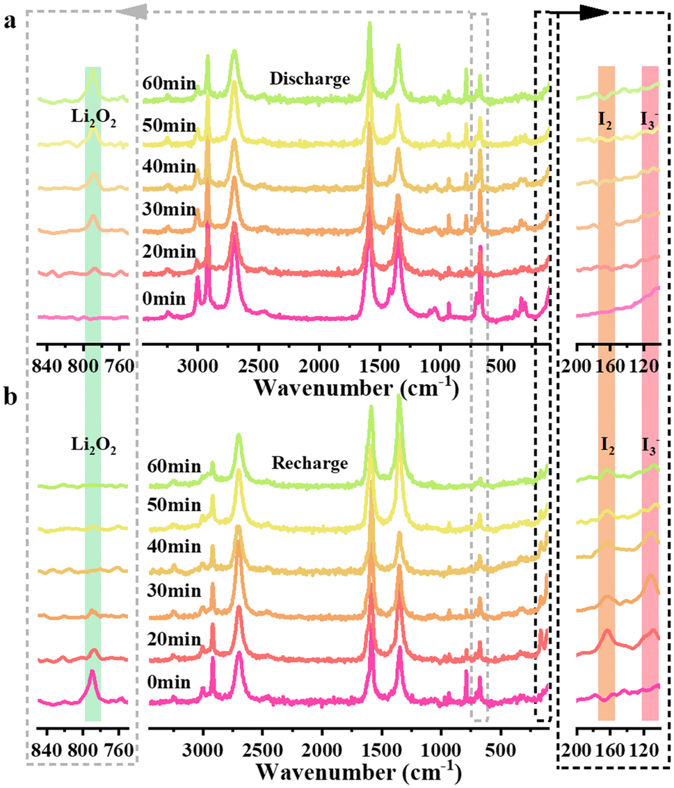 | ||
| Fig. 5 In situ Raman spectra of the MWCNT cathode during discharge (a) and recharge (b) processes at 0.3 mA cm−2. | ||
The use of SP70 QSSE also improves the anode processes in the cycling of iodide-assisted LOBs, except for protection from corrosion to the Li anode, owing to the effective blockage of the iodides by the SP70 QSSE. Fig. 6 illustrates the role of the QSSEs in homogenizing lithium stripping/plating processes. Fig. 6a depicts the total profiles of the Li||Li symmetrical cells with the pristine PVDF and SP70 QSSEs cycled in 1 mol L−1 LiClO4/DMSO electrolyte at the current density of 0.1 mA cm−2. The voltage gap in the Li||Li symmetrical cell with the pristine PVDF QSSE (0.185 V) is much higher than the one with the SP70 QSSE (0.022 V) in the initial 10 h (Fig. 6b) owing to enhanced ionic conductivity by high loading SiO2, and after 100 h, the former rapidly increases to 2.2 V, indicating the failure of the cell due to the quick pulverization of Li electrodes. In contrast, the latter remains stable after 600 h of cycling, where the potential gaps are 0.028 V after 200 h, 0.062 V after 400 h and 0.158 V after 600 h (Fig. 6c–e), indicating the uniform Li+ flux during the Li stripping/plating conducted by continuous SiO2 frameworks through the SP70 QSSE.
 | ||
| Fig. 6 Cycling in the Li||Li symmetric cells at 0.1 mA cm−2 with the SP70 and PVDF QSSEs (a) and zoom-in plots at different stages (b–e). | ||
Moreover, the incorporation of high loading SiO2 nanoparticles is observed to effectively stabilize the composite QSSEs. The total XPS spectra for the pristine PVDF and SP70 QSSEs before and after 10 cycles in the LOBs are displayed in Fig. S17.†Fig. 7a compares the fitting results of the resolved C1s signal of the pristine PVDF QSSE. Before cycling, three peaks at 284.8, 286.33 and 290.72 eV are assigned to the C–C, C–O and C–F groups, respectively, which agrees with previous studies.40 After 10 cycles, four peaks are observed at 284.8, 286.49, 288.43 and 289.87 eV, corresponding to C–C, C–O, Li2CO3 and C–F, respectively.54,55Fig. 7b illustrates the fitting of the O1s signal, where only the C–O peak appears at 531.96 eV before cycling. After 10 cycles, two peaks occur at 531.75 and 532.78 eV corresponding to C–O and Li2CO3, respectively. Fig. 7c shows the fitted F1s signal, where only one peak is exhibited at 687.8 eV, corresponding to C–F. After 10 cycles, two peaks at 684.84 and 688.28 eV are observed, which are attributed to Li–F and C–F groups.41 The results indicate that Li2CO3 and Li–F bond appear after cycling in lithium–oxygen batteries, where the former suggests the decomposition of the PVDF QSSE and the latter is associated with the reaction with Li anode and the formation of F-rich SEI layer due to the close contact, explaining the quick damage of the pristine PVDF QSSE after 102 cycles, as shown in Fig. S14a.†
 | ||
| Fig. 7 Fitting of the resolved XPS C1s (a), O1s (b), and F1s (c) signals of the PVDF QSSE before and after 10 cycles. Fitting of the resolved XPS C1s (d), O1s (e), and F1s (f) signals of the SP70 QSSE before and after 10 cycles. | ||
Fig. 7d illustrates the fitting of the resolved C1s spectrum of the SP70 QSSE, where three peaks are observed at 284.8, 286.3 and 290.73 eV before cycling, representing C–C, C–O and C–F groups, respectively. After 10 cycles, three peaks at 284.8, 286.28 and 290.71 eV are attributed to C–C, C–O and C–F, respectively. Fig. 7e displays the fitting of the resolved O1s signal, where the C–O peak occurs at 531.95 eV before cycling. After 10 cycles, the peak appears at 531.92 eV, corresponding to the C–O group. Fig. 7f shows the fitted F1s signal, where a peak at 687.55 eV corresponds to the C–F group before cycling. After 10 cycles, two peaks occur at 684.86 and 688.76 eV, which are assigned to Li–F and C–F, respectively. Fig. S18† depicts the fitted Si2p signal, where only the Si–O group is observed before and after battery cycling. The results indicate that the addition of SiO2 nanoparticles significantly improves chemical stability because only Li–F appears in the SP70 QSSE after LOB cycling, which is consistent with the SEM analysis shown in Fig. S14b and c.†
4. Conclusion
We successfully synthesized a robust and flexible PVDF-based QSSE with high-loading PMMA-modified SiO2 nanoparticles. The optimized SP70 QSSE (70 wt% of SiO2) exhibited excellent Li+ conductivity of 1.48 × 10⁻³ S cm−1 and resistance to the shuttling of iodides (I− and I3−) and other harmful species, together with superior Young's modulus (12 GPa on average) and flexibility to prevent possible Li dendrite penetration. Investigations showed that the interfacial ion transfer mechanism was predominant by continuous SiO2 nanoparticle networks across the SP70 QSSE. Furthermore, the incorporation of SiO2 significantly enhances the thermal stability and chemical resistance of PVDF-based QSSEs. The intimate interfacial contact between the SP70 QSSE and the Li anode formed an F-rich SEI layer on the Li surface and facilitated the uniform stripping/plating of Li. Consequently, the lifespan of iodine-assisted LOBs was extended from 103 cycles with the pristine PVDF QSSE to 402 cycles with the SP70 QSSE at 1.0 A g−1 and 1000 mA h g−1, and the full discharge capacity was also approximately doubled from 24277 to 45336 mA h g−1. The excellent performance and cost-effectiveness of the composite QSSE provide a prospective pathway for the practical application of LOBs.
Data availability
Data will be made available upon request.Conflicts of interest
There are no conflicts to declare.Acknowledgements
The authors sincerely acknowledge the financial support from the National Natural Science Foundation of China (No. 52474431), Jiangsu Specially Appointed Professor Fund by Jiangsu Education Department, Engineering and Physical Sciences Research Council (No. EP/S032886/1), and RSC research grant (R21-220003) and are grateful for the assistance of Shenzhen Institute of Terahertz Technology and Innovation for the Terahertz time-domain spectroscopy analysis.References
- W.-J. Kwak, Rosy, D. Sharon, C. Xia, H. Kim, L. R. Johnson, P. G. Bruce, L. F. Nazar, Y.-K. Sun, A. A. Frimer, M. Noked, S. A. Freunberger and D. Aurbach, Chem. Rev., 2020, 120, 6626–6683 CrossRef CAS PubMed.
- Y. Zhou, W. Feng, Y. Xu, X. Liu, S. Wang, Z. Lv, X. Li, E. Burcar, Z. Wang and Z. Yang, Eng. Sci., 2023, 28, 1060 Search PubMed.
- X. Wu, N. Liu, Z. Guo, M. Wang, Y. Qiu, D. Tian, B. Guan, L. Fan and N. Zhang, Energy Storage Mater., 2020, 28, 153–159 CrossRef.
- X. Chi, M. Li, J. Di, P. Bai, L. Song, X. Wang, F. Li, S. Liang, J. Xu and J. Yu, Nature, 2021, 592, 551–557 CrossRef CAS PubMed.
- Y. Lu, X. Rong, Y.-S. Hu, L. Chen and H. Li, Energy Storage Mater., 2019, 23, 144–153 CrossRef.
- P. G. Bruce, S. A. Freunberger, L. J. Hardwick and J.-M. Tarascon, Nat. Mater., 2011, 11, 19–29 CrossRef PubMed.
- G. Zhang, D. Zhang, R. Yang, Y. Du, N. Wang, Z. Guo, X. Mai and F. Dang, Adv. Funct. Mater., 2023, 33, 2304981 CrossRef CAS.
- K.-N. Jung, J.-I. Lee, J.-H. Jung, K.-H. Shin and J.-W. Lee, Chem. Commun., 2014, 50, 5458 RSC.
- W.-B. Luo, S.-L. Chou, J.-Z. Wang, Y.-M. Kang, Y.-C. Zhai and H.-K. Liu, Chem. Commun., 2015, 51, 8269–8272 RSC.
- Z. Luo, G. Zhu, L. Yin, F. Li, B. B. Xu, L. Dala, X. Liu and K. Luo, ACS Appl. Mater. Interfaces, 2020, 12, 27316–27326 CrossRef CAS PubMed.
- H.-S. Woo, Y.-B. Moon, S. Seo, H.-T. Lee and D.-W. Kim, ACS Appl. Mater. Interfaces, 2017, 10, 687–695 CrossRef PubMed.
- J. Yi, X. Liu, S. Guo, K. Zhu, H. Xue and H. Zhou, ACS Appl. Mater. Interfaces, 2015, 7, 23798–23804 CrossRef CAS PubMed.
- S. H. Lee, J. B. Park, H. S. Lim and Y. K. Sun, Adv. Energy Mater., 2017, 7, 1602417 CrossRef.
- B. J. Bergner, A. Schürmann, K. Peppler, A. Garsuch and J. R. Janek, J. Am. Chem. Soc., 2014, 136, 15054–15064 CrossRef CAS PubMed.
- D. Sun, Y. Shen, W. Zhang, L. Yu, Z. Yi, W. Yin, D. Wang, Y. Huang, J. Wang, D. Wang and J. B. Goodenough, J. Am. Chem. Soc., 2014, 136, 8941–8946 CrossRef CAS PubMed.
- Y. Chen, S. A. Freunberger, Z. Peng, O. Fontaine and P. G. Bruce, Nat. Chem., 2013, 5, 489–494 CrossRef CAS PubMed.
- T. Zhang, K. Liao, P. He and H. Zhou, Energy Environ. Sci., 2016, 9, 1024–1030 RSC.
- A. Nakanishi, M. L. Thomas, H.-M. Kwon, Y. Kobayashi, R. Tatara, K. Ueno, K. Dokko and M. Watanabe, J. Phys. Chem. C, 2018, 122, 1522–1534 CrossRef CAS.
- H. Zhang, H. Liu, J. Mai, Y. Ren, R. Wang, X. Li, Q. Deng and N. Wang, Eng. Sci., 2022, 20, 199–208 CAS.
- Z. Chen, M. Guan, Y. Cheng, H. Li, G. Ji, H. Chen, X. Fu, D. E. Awuye, Y. Zhu, X. Yin, Z. Man and C. Wu, Adv. Compos. Hybrid Mater., 2023, 6, 219 CrossRef CAS.
- S. Hua, J. L. Li, M. X. Jing, F. Chen, B. W. Ju, F. Y. Tu, X. Q. Shen and S. B. Qin, Int. J. Energy Res., 2020, 44, 6452–6462 CrossRef CAS.
- J. Li, M.-x. Jing, R. Li, L.-x. Li, Z.-h. Huang, H. Yang, M.-q. Liu, S. Hussain, J. Xiang and X.-q. Shen, ACS Appl. Polym. Mater., 2022, 4, 7144–7151 CrossRef CAS.
- G. Zheng, T. Yan, Y. Hong, X. Zhang, J. Wu, Z. Liang, Z. Cui, L. Du and H. Song, Nat. Commun., 2023, 14, 2268 CrossRef CAS PubMed.
- S. Khan, C. Fang, Y. Ma, M. U. Haq, M. Nisar, G. Xu, Y. Liu and G. Han, J. Electrochem. Soc., 2021, 168, 022504 CrossRef CAS.
- K. Luo, G. Zhu, Y. Zhao, Z. Luo, X. Liu, K. Zhang, Y. Li and K. Scott, J. Mater. Chem. A, 2018, 6, 7770–7776 RSC.
- T. Zhang, J. Li, X. Li, R. Wang, C. Wang, Z. Zhang and L. Yin, Adv. Mater., 2022, 34, 2205575 CrossRef CAS PubMed.
- D. Lin, W. Liu, Y. Liu, H. R. Lee, P.-C. Hsu, K. Liu and Y. Cui, Nano Lett., 2015, 16, 459–465 CrossRef PubMed.
- H. Liang, L. Wang, A. Wang, Y. Song, Y. Wu, Y. Yang and X. He, Nano-Micro Lett., 2023, 15, 42 CrossRef CAS PubMed.
- A. Manuel Stephan and K. S. Nahm, Polymer, 2006, 47, 5952–5964 CrossRef.
- D. Xie, M. Zhang, Y. Wu, L. Xiang and Y. Tang, Adv. Funct. Mater., 2019, 30, 1906770 CrossRef.
- R. Murugan, V. Thangadurai and W. Weppner, Angew. Chem., Int. Ed., 2007, 46, 7778–7781 CrossRef CAS PubMed.
- N. Kamaya, K. Homma, Y. Yamakawa, M. Hirayama, R. Kanno, M. Yonemura, T. Kamiyama, Y. Kato, S. Hama, K. Kawamoto and A. Mitsui, Nat. Mater., 2011, 10, 682–686 CrossRef CAS PubMed.
- H. Aono, E. Sugimoto, Y. Sadaoka, N. Imanaka and G.-y. Adachi, Bull. Chem. Soc. Jpn., 1992, 65, 2200–2204 CrossRef CAS.
- T. Asano, A. Sakai, S. Ouchi, M. Sakaida, A. Miyazaki and S. Hasegawa, Adv. Mater., 2018, 30, 1803075 CrossRef PubMed.
- D. Lin, P. Y. Yuen, Y. Liu, W. Liu, N. Liu, R. H. Dauskardt and Y. Cui, Adv. Mater., 2018, 30, 1802661 CrossRef PubMed.
- X. Chen, B. Put, A. Sagara, K. Gandrud, M. Murata, J. A. Steele, H. Yabe, T. Hantschel, M. Roeffaers and M. Tomiyama, Sci. Adv., 2020, 6, eaav3400 CrossRef CAS PubMed.
- G. H. Bogush, M. A. Tracy and C. F. Zukoski, J. Non-Cryst. Solids, 1988, 104, 95–106 CrossRef CAS.
- J. Li, R. Hu, H. Zhou, S. Tao and Y. Wang, J. Mater. Sci.: Mater. Electron., 2020, 31, 2708–2719 CrossRef CAS.
- W. Liu, W. Li, D. Zhuo, G. Zheng, Z. Lu, K. Liu and Y. Cui, ACS Cent. Sci., 2017, 3, 135–140 CrossRef CAS PubMed.
- W. Chen, Z. Luo, X. Zhuge, Z. Ding, Y. Ren, A. Loya, Y. Li and K. Luo, J. Energy Storage, 2022, 50, 104580 CrossRef.
- D. Yuan, C. Ji, X. Zhuge, A. Chai, L. Pan, Y. Li, Z. Luo and K. Luo, Appl. Surf. Sci., 2023, 613, 155863 CrossRef CAS.
- K. Naresh, K. A. Khan, R. Umer and W. J. Cantwell, Mater. Des., 2020, 190, 108553 CrossRef CAS.
- C. Ou, H. Zhang, D. Ma, H. Mu, X. Zhuge, Y. Ren, M. Bayati, B. B. Xu, X. Liu, X. Zou and K. Luo, EcoMat, 2024, 6, e12481 CrossRef CAS.
- K. Liu, H. Cheng, Z. Wang, Y. Zhao, Y. Lv, L. Shi, X. Cai, Z. Cheng, H. Zhang and S. Yuan, Adv. Energy Mater., 2024, 14, 2303940 CrossRef CAS.
- X. Yang, J. Liu, N. Pei, Z. Chen, R. Li, L. Fu, P. Zhang and J. Zhao, Nano-Micro Lett., 2023, 15, 74 CrossRef CAS PubMed.
- J. F. Federici, J. Infrared, Millimeter, Terahertz Waves, 2012, 33, 97–126 CrossRef.
- I. Amenabar, F. Lopez and A. Mendikute, J. Infrared, Millimeter, Terahertz Waves, 2013, 34, 152–169 CrossRef.
- J. Zheng and Y.-Y. Hu, ACS Appl. Mater. Interfaces, 2018, 10, 4113–4120 CrossRef CAS PubMed.
- T. Zhang, K. Liao, P. He and H. Zhou, Energy Environ. Sci., 2016, 9, 1024–1030 RSC.
- L. Johnson, C. Li, Z. Liu, Y. Chen, S. A. Freunberger, P. C. Ashok, B. B. Praveen, K. Dholakia, J.-M. Tarascon and P. G. Bruce, Nat. Chem., 2014, 6, 1091–1099 CrossRef CAS PubMed.
- F. S. Gittleson, K. P. C. Yao, D. G. Kwabi, S. Y. Sayed, W. H. Ryu, Y. Shao-Horn and A. D. Taylor, ChemElectroChem, 2015, 2, 1446–1457 CrossRef CAS.
- Z. Gao, J. Yao, J. Yan, J. Sun, C. Du, Q. Dai, Y. Su, J. Zhao, J. Chen, X. Li, H. Li, P. Zhang, J. Ma, H. Qiu, L. Zhang, Y. Tang and J. Huang, Small, 2024, 20, 2311739 CrossRef CAS PubMed.
- X. Gao, Y. Chen, L. Johnson and P. G. Bruce, Nat. Mater., 2016, 15, 882–888 CrossRef CAS PubMed.
- T. Li, C. Wang, J. Cheng, J. Guo, A. Xiao, H. Hou, Q. Wang, B. Wang, X. Chen and G. Cui, ACS Appl. Mater. Interfaces, 2020, 12, 12857–12866 CrossRef CAS PubMed.
- H. Mu, K. Luo, Y. Pang, X. Zhuge, Z. Ding, Y. Ren, D. Li, Z. Luo, B. B. Xu, M. Bayati and X. Liu, Chem. Eng. J., 2023, 475, 146489 CrossRef CAS.
Footnotes |
| † Electronic supplementary information (ESI) available. See DOI: https://doi.org/10.1039/d5nr00872g |
| ‡ First authors. |
| This journal is © The Royal Society of Chemistry 2025 |