
 Open Access Article
 This Open Access Article is licensed under a
 Creative Commons Attribution 3.0 Unported Licence
In situ synthesis of bimetallic chalcogenides with highly conductive carbon nanotubes for efficient symmetric hybrid supercapacitors†
Soumyajit
Jana‡
a,
Sampath
Karingula‡
a,
Anjana
Sajeevan
a,
Phani Kumar
V. V. N.
b and
Yugender Goud
Kotagiri
 *a
*a
aDepartment of Chemistry, Indian Institute of Technology Palakkad, Palakkad, Kerala 678 557, India. E-mail: yugenderkotagiri@iitpkd.ac.in
bCentre for Automotive Energy Materials, International Advanced Research Centre for Powder Metallurgy and New Materials (ARCI), Chennai 600113, Tamil Nadu, India
First published on 27th March 2025
Abstract
Achieving high energy density and long cycle stability in energy storage devices necessitates excellent electrochemical performance, which often relies on the innovative structural design of the materials under investigation. Therefore, hybrid supercapacitors are crucial in the realm of energy storage devices. The elevated energy and power densities, combined with various energy storage mechanisms, significantly improve electrochemical performance. Here, we developed a highly efficient electrode material, carbon nanotube-metal chalcogenides (CNT-CuNiSe2), using a simple one-pot reflux method (in situ). The enhanced energy storage performance was achieved by synergising CuNiSe2 with the pi-cloud of CNTs, resulting in enhanced specific capacitance retention over prolonged cycling stability. The hybrid supercapacitor electrode was formed by combining conducting carbon cloth (CC) with CNT-CuNiSe2 as a hybrid material, referred to as the CC/CNT-CuNiSe2 material. The fabricated hybrid electrode materials demonstrated excellent potential for energy storage. CC/CNT-CuNiSe2 exhibited excellent energy storage capabilities, achieving a specific capacitance of 957.06 F g−1 at 1 A g−1. Hybrid supercapacitors with high energy and power density were developed using conducting carbon cloth and CNT-CuNiSe2, designated as CC/CNT-CuNiSe2//CC/CNT-CuNiSe2. The hybrid capacitor device demonstrated a capacitance of 265.586 F g−1, along with an energy density of 82.99 W h kg−1 at a power density of 1511.35 W kg−1. When charged and discharged at 4 A g−1, the hybrid capacitor device displayed an impressive capacitance retention of 101.3% over 6000 continuous cycles.
1. Introduction
In this 21st century, two major problems are global warming and the energy crisis. Currently, energy production and fuel economy mostly depend on fossil fuels. In this context, energy storage devices and renewable energy sources, such as wind, solar, and hydrogen energy, play a crucial role in meeting the continuous energy demand. Energy storage devices, such as batteries and supercapacitors, are widely employed in modern electronic devices to store electrical energy. Batteries offer high energy density and can power devices throughout the day, typically requiring an hour to recharge when depleted. However, batteries have relatively shorter lifespans, are often expensive, and can reach high temperatures during ignition or explosion, leading to potential safety risks. For rapid power delivery—characterized by high power density, quick recharge times and the ability to endure a substantial number of cycles (>106)—devices such as capacitors, particularly supercapacitors, are widely employed in smart electronics, electric vehicles, and electromechanical and electrohydrostatic flight control actuation systems.1 Batteries and supercapacitors differ in their charge storage mechanisms. In lithium-ion batteries, the incorporation of Li ions facilitates redox reactions in the bulk electrode materials, which are governed by diffusion and may occur slowly.2 Consequently, the charge transfer mechanism in lithium-ion batteries is often limited.In contrast, supercapacitors (SCs) are energy-storage devices that can store 100 times more charge than traditional capacitors. SCs operate through electrostatic interactions at the electrode/electrolyte interface via electrochemical double-layer capacitance (EDLC) or by transferring charge to a layer of redox molecules on the electrode's surface.3 Therefore, SCs can provide high power density and energy density for a limited period, making their application different from batteries. It has been noted that Li-ion batteries and supercapacitors have low power and energy densities.4 To overcome the issues related to the use of metal oxides (Co3O4, RuO2, MnO2) in energy storage,5–7 metal chalcogenides (NiSe2, MoS2, MoSe2, CoSe2)8–11 have been employed as electrode materials for energy-storage devices, such as supercapacitors, which are best known as pseudo-capacitors. In recent trends, metal chalcogenides have drawn significant attention from researchers and the scientific community due their potential applications in various fields, such as an energy-storage materials, electrocatalysts, and gas sensing.12–14 Metal selenides (MSes), from the family of metal chalcogenides, have been widely explored and used as electrode materials in both EDLC and pseudo-capacitors. This is due to their inheritance “d” electronic structure, adaptable coordination environment, higher electrical conductivity, low electronegativity, and the participation of filled 3d orbitals of Se and vacant 3d orbitals of metals in electron delocalization. As a result, charge is dispersed around the metal selenides, making them favourable for charge storage applications, such as supercapacitors.15,16 Monometallic selenides, such as NiSe2, have been notably recognized for their potential in supercapacitor applications.17 However, NiSe2 offers limited energy and power density, and less surface area. Other MSe compounds, including CuSe and CoSe2, have also exhibited low energy density, power density, and reduced capacitance retention.18,19 Therefore, bimetallic and multi-metal selenide (MMSe) compositions, comprising manganese, cobalt, copper, and iron, have been investigated as they may benefit from synergistic effects that can enhance the electrochemical activity beyond the limitations of monometallic compounds.20,21 For instance, CuS2@Cu7Se4@NC was synthesized by Zhu et al. and showed high performance for an asymmetric supercapacitor with a capacitance of 660 F g−1 and density of 599.7 W kg−1, while Molaei et al. synthesized hollow spheres of FeCoSe2/NiCoLDH via a hydrothermal method, and the composite exhibited a specific capacitance of 1305 C g−1 and an energy density of 55.45 W h k−1.22,23 Other examples include r-GO/CoNiSe2, which was synthesized via a hydrothermal process by Li et al., and exhibited a specific capacitance of 2249.7 F g−1 and an energy density of 143.2 W h kg−1 at 0.825 kW kg−1 power density, and NiSe2/MnSe/r-GO, which demonstrated an energy density of 51.4 W h kg−1 at a power density of 800.7 W kg−1, as reported by Q. Lu et al. and G. Zhang et al., respectively.24,25
Despite their high specific capacitance, a significant problem encountered by pseudo-capacitor materials, such as MSes and MMSes, is their comparatively poor power density compared to EDLCs. This is primarily due to the slower nature of faradaic processes compared to non-faradaic processes. Moreover, pseudo-capacitor electrodes are more susceptible to volumetric alterations during charge and discharge cycles, which can reduce their cycling stability and mechanical integrity.26 To overcome this issue, hybrid supercapacitors were introduced, combining EDLC and pseudo-capacitors to provide a large surface area where electrolyte ions can be stored via both faradaic and non-faradaic mechanisms. This approach results in enhanced energy density, power density, and long cyclic stability. These hybrid devices typically employ non-faradaic materials, such as carbon-based substances (CNT, GO, CNF, graphite, carbon sponges, and carbon nanosheets), in combination with faradaic materials like metal chalcogenides, metal oxide, conducting polymers, organic redox polymers, and MOF-based substances.10,27–30. The role of carbon as a support or coating on metal selenide particles is essential in inhibiting their aggregation during the electrochemical process. This is due to the strong electrostatic interaction between carbonaceous materials and metal selenide nanoparticles. Such interactions enhance the electrostatic interaction between the active material and the electrolyte, leading to enhanced electrochemical performance.10,27 In addition, carbon-based materials are easy to process, low in toxicity, lightweight, and have tunable porosity. In addressing environmental challenges, carbon nanotubes (CNT) have been thoroughly investigated for use in energy storage devices due to their zero-band gap, remarkable electrical conductivity, and mechanical strength. These properties make them ideal for supercapacitors (SCs) and flexible electronic storage. Potential applications of CNTs encompass portable electronic products such as wearables, electronic paper, rollable displays, computing systems, and mobile phones.31–33
Numerous synthesis protocols have been developed for the formation of hybrid materials for energy storage, including one-pot synthesis methods such as one-step hydrothermal and wet chemical approaches. For instance, B. G. Amin et al. synthesized NiCo2Se4/rGO on Ni foam via one-step hydrothermal synthesis at 145 °C for 8 h.34 Furthermore, there are two other methods commonly used: in situ and ex situ synthesis. As an example, NiCo2S4 on carbon cloth was synthesized by Yan et al. at 160 °C for 12 h, and. the CeO2/CeS2 nanocomposite was fabricated by Bibi et al. using a hydrothermal method.35,36 All of the above fabrication protocols offer advantages, such as the ability to control the size and morphology of the composite. However, the one-pot method has the disadvantage of providing less control over structural morphology and stability. Although hydrothermal and solvothermal approaches are traditional and widely explored, these methods, despite being controlled synthesis pathways, are not environmentally friendly or cost-effective. And these proptocols requires high temperature, high pressure, and long duration for the nanomaterials synthesis.37–39 In contrast, a simple one-pot synthesis via an in situ approach using liquid-phase reduction techniques offers an effective alternative for synthesizing bimetallic nanomaterials. This approach is eco-friendly, economical, and essential for controlling the form and size of nanomaterials by adjusting reaction parameters and mole ratios.40,41
In this study, we synthesized CNT-CuNiSe2 using liquid-phase reduction methods with an in situ approach for application in hybrid supercapacitor devices. This electrode exhibited a distinctive electron transport mechanism, ensuring high energy density and an efficient synthesis process. Furthermore, the physical characterization of CNT-CuNiSe2 was conducted using FT-IR, Raman spectroscopy, and XRD. The morphology and surface properties of CNT-CuNiSe2 were analyzed through FESEM, HRTEM, and BET isotherms. Electrochemical studies of all composites were performed using CV, GCD, and EIS techniques with both three-electrode and two-electrode (flat cell) configurations in a 6 M KOH electrolyte. In addition, CNT-CuNiSe2 demonstrated excellent electrical conductivity and substantial specific capacitance. The CNT-CuNiSe2-based device, featuring carbon cloth, demonstrated an energy density of 82.99 W h kg−1 and the highest power density of 48.25 kW kg−1. Additionally, the CNT-CuNiSe2 device demonstrated enhanced endurance, maintaining performance over 6000 continuous galvanostatic charge and discharge cycles. After 6000 cycles, the CNT-CuNiSe2 device retained 101.3% of specific capacitance, and demonstrating remarkable coulombic efficiency of 93.6%. This represents the first documented approach for the cost-effective and environmentally friendly synthesis of CNT-CuNiSe2, along with the development of 1.5 V electrodes designed for hybrid supercapacitor applications.
2. Experimental section
2.1 Chemicals and materials
Copper chloride dihydrates (CuCl2·2H2O), nickel chloride hexahydrate (NiCl2·6H2O, extra pure, AR, 99%), sodium selenite anhydrous (Na2SeO3, AR, 99%), sodium borohydride (NaBH4), multi-walled carbon nanotubes (MWCNT Type-6, Sigma Aldrich), sulfuric acid (H2SO4, 99%), nitric acid (HNO3, 98%), 5% Nafion solution, isopropyl alcohol, N-methyl pyrrolidone (NMP, 99%), conducting carbon cloth (SRL), Super-p carbon, and polyvinylidene fluoride (PVDF) were purchased from The Electrode Store (TES), India.2.2. Synthesis of functionalized CNTs
Multi-walled carbon nanotubes (CNTs) were utilized as supports in our hybrid supercapacitor composite. Before application, the carbon nanotubes (CNTs) underwent functionalization with –COOH groups following the established protocol. Briefly, 500 mg of multi-walled carbon nanotubes (MWCNTs) were uniformly dispersed in 75 ml of 3 M nitric acid (HNO3). The solution then underwent sonication for a duration of 5 min, followed by stirring for 22–24 h at a temperature of 60 °C. The resulting black solid suspension was subsequently rinsed gently by centrifuging it several times with Milli-Q water until a neutral pH of 7 was achieved. The obtained black solid was then dried in an oven at 70 °C for 12 h. In this stage, HNO3 facilitated the oxidation of the CNTs by triggering the development of the –COOH group along the sidewalls and at the ends of the CNT structure. This phenomenon results in effects that subsequently enhance the loading of metal nanoparticles with a uniform distribution. This process of functionalization can enhance the dispersion of CNTs in catalytic ink by increasing their solubility.362.3. In situ synthesis of CNT-CuNiSe2
Using the in situ approach, CNT-CuNiSe2 was synthesized. The standard process involved dissolving 0.35 g of NaBH4 in 100 mL of deionized water. Next, Na2SeO3 powder (0.345 g) was added to the mixture and stirred until total dissolution. Meanwhile, in 100 mL of deionized water, 0.4 g of functionalized CNTs, 0.237 g of NiCl2·6H2O, and 0.118 g of CuCl2·2H2O were simultaneously dissolved with the help of a 10 ml disposable syringe. During sample preparation, a continuous nitrogen flow was introduced to prevent the key intermediates from easily oxidizing into high valences during selenium reduction.42 Nickel and copper salts solutions were introduced to the reaction vessel after a continuous flow of N2 gas for the 10 minutes, and the solution kept stirring for 2 hours at 90 °C. Scheme 1 illustrates the CNT-CuNiSe2 synthesis protocol. The black precipitate was separated by centrifugation after stirring, and it was then vacuum-dried for 12 h at 50 °C. Following the same synthesis protocol, we also synthesized Cu1−XNiXSe2, NiSe2, CuSe2, CNT-NiSe2, and CNT-CuSe2, respectively.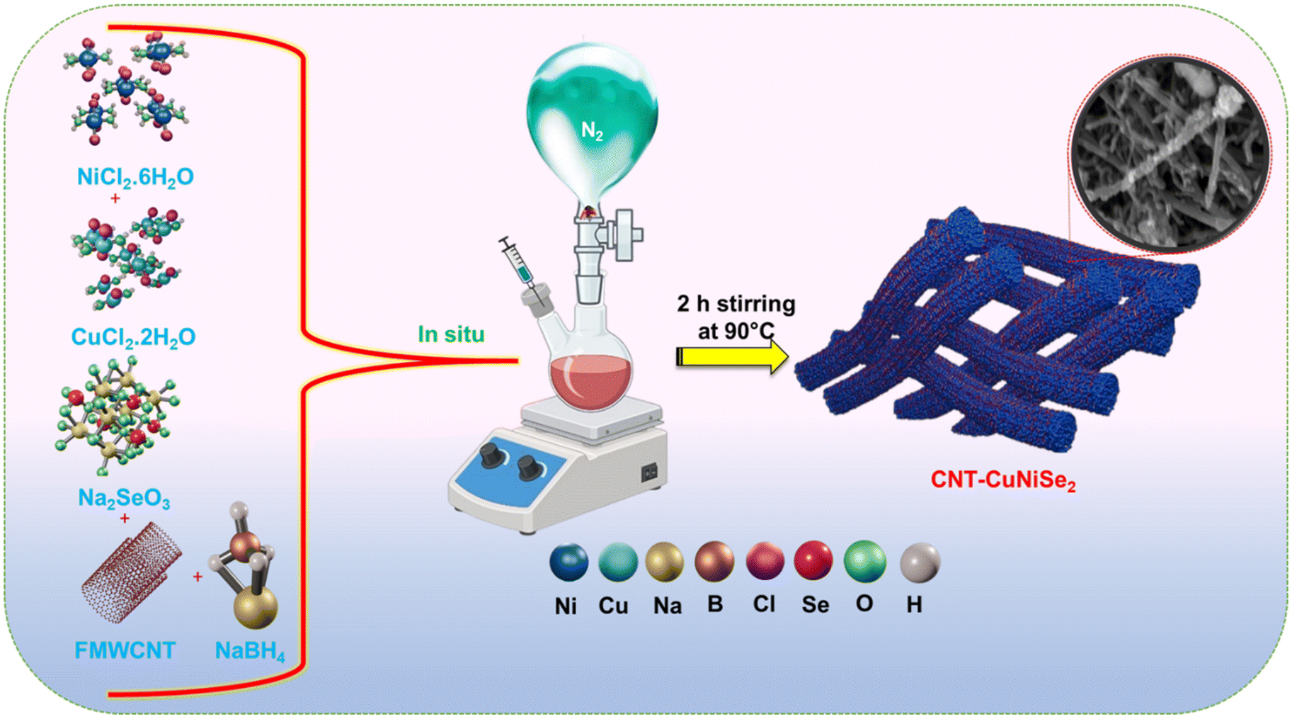 | ||
| Scheme 1 Schematic of the in situ synthesis of CNT-CuNiSe2. | ||
2.4. Sample preparation for electrochemical characterization
![[thin space (1/6-em)]](https://www.rsc.org/images/entities/char_2009.gif) :1:0.05. The resultant mixture was sonicated for 2 h, at 1 h intervals. Next, 3 μL of the prepared ink was coated twice on the GCE with the help of a micropipette, and the modified electrode was dried overnight at room temperature. The modified GCE was named CNT-CuNiSe2.
:1:1, was taken followed by the addition of 400 μL of the NMP in a mortar, and then ground well with a pestle for 60 min until a uniform slurry was formed. The black slurry was coated onto the carbon cloth by drop casting, and the coated carbon cloth was dried overnight at 80 °C. The coated cloth was weighed out, and the amount of the CNT-CuNiSe2 was found to be 0.002 g. The carbon cloth was named as CC/CNT-CuNiSe2.
:1:0.05. The resultant mixture was sonicated for 2 h, at 1 h intervals. Next, 3 μL of the prepared ink was coated twice on the GCE with the help of a micropipette, and the modified electrode was dried overnight at room temperature. The modified GCE was named CNT-CuNiSe2.
:1:1, was taken followed by the addition of 400 μL of the NMP in a mortar, and then ground well with a pestle for 60 min until a uniform slurry was formed. The black slurry was coated onto the carbon cloth by drop casting, and the coated carbon cloth was dried overnight at 80 °C. The coated cloth was weighed out, and the amount of the CNT-CuNiSe2 was found to be 0.002 g. The carbon cloth was named as CC/CNT-CuNiSe2.
2.5. Instrumentation
Morphological analysis of our synthesized materials was performed by field emission electron microscopy (FESEM, Gemini SEM 300, 15 kV) and HRTEM (HEOL, JAPAN, JEM-2100 Plus), and the images were processed by ImageJ software. The composition of the materials was assessed by elemental mapping utilizing energy-dispersive X-ray (EDX) spectroscopy. X-Ray diffraction (XRD) patterns were obtained a using Rigaku XRD Smart Lab system in the range of 20° to 90°. FT-IR spectra were recorded in the range of 400–4000 cm−1 using an FT-IR instrument from Shimadzu Scientific Instruments. To determine the crystal structure, a Raman spectrophotometer (Horiba Labram HR Evo) was employed. Brunauer–Emmett–Teller (BET) analysis was done on a surface area analyzer from Quantachrome.2.6. Electrochemical characterization
Electrochemical characterization was performed with the help of cyclic voltammetry (CV), galvanostatic charge and discharge (GCD), and electrochemical impedance spectroscopy (EIS) on a potentiostat/galvanostat (Model 6054e, CH instrument, USA). The three-electrode setup was established utilizing a GCE with a working area of 0.0706 cm−2, Hg/HgO in 1 M KOH as the reference electrode, and Pt wire as the counter electrode, all immersed in 6 M KOH electrolyte. In the two-electrode setup, the cathode and anode were made of the same materials. Electrochemical impedance spectroscopy (EIS) was performed utilizing a sinusoidal alternating frequency spanning from 0.01 Hz to 105 Hz, accompanied by an amplitude of 5 mV and a steady direct current bias potential of 0.3 V.3. Results and discussion
3.1 Material characterization
The one-pot synthesis method serves as a clear and efficient approach that maximizes time and energy resources. This established method integrates the precursors for both materials into a unified reaction, enabling the simultaneous synthesis of two materials and the formation of hybrid structures in a single step. Additionally, the in situ synthesis of TMC-based hybrids is a frequently studied approach, as it promotes effective interfacial interactions and allows for direct control over the morphologies. In this approach, one component serves as a structural backbone, while its counterpart undergoes nucleation and growth on the backbone. Taking advantage of this method, an in situ approach was employed here in a one-pot synthesis to produce the CNT-CuNiSe2 composite using a liquid-phase reduction method, as schematically shown in Scheme 1. In this process, functionalized multi-walled carbon nanotubes (MWCNTs) were added to the reaction vessel along with Ni and Cu salts, Se sources, and NaBH4 as reducing agent in an aqueous medium under inert conditions. The functionalized MWCNTs’ surfaces were coated with CuNiSe2, resulting in the formation of the CNT-CuNiSe2 composite. We then tested the energy-storage performance of the CNT-CuNiSe2, which showed satisfactory results.FT-IR is a useful technique for characterizing CNT-based monometallic and bimetallic selenide materials at the preliminary stage. We developed a green approach for the synthesis of our materials via an in situ reaction and liquid-phase reduction methods in one pot. In this one-pot process, CNTs and an equimolar ratio of Cu and Ni salts were added, resulting in the desired CNT-CuNiSe2 product. In Fig. 1(a), peaks corresponding to the –C![[double bond, length as m-dash]](https://www.rsc.org/images/entities/char_e001.gif) C bond at 1636 cm−1, –M–Se bond in the 700–650 cm−1 range, and a broad peak in the 3400–3200 cm−1 range due to –O–H groups were observed. These peaks were also observed for CNT-NiSe2 and CNT-CuSe2.43 Raman spectra was recorded in the 400 to 2000 cm−1 range and shown in Fig. 2(b). The spectrum showed two characteristic peaks at around 1300–1400 cm−1, corresponding to the D band. This peak was attributed to structural defects in the walls of the nanotubes. Another peak corresponding to the G band was observed at 1500–1600 cm−1, which was related to the structural vibration of carbon atoms in the graphene layer for all three composites.44 The ID/IG ratio for CNT-CuNiSe2 was 1.0101, while for CNT-NiSe2 and CNT-CuSe2, the ratios were 1.0086 and 1.00041, respectively. This indicated that the enhancement of the D band in CNT-CuNiSe2 could be attributed to the defects and vacancies created by acid treatment and the incorporation of Cu and Ni with the CNTs.40Fig. 1(c) shows the XRD diffraction peaks of the synthesized energy materials. The pure crystalline CuSe2 diffraction peaks (corresponded to JCPDS card No. 01-082-0446) are observed at 2θ values of 27.99, 44.88, 50.03 and 53.30 are correspond to different phase planes of (011), (020), (221), (031), and (131), respectively.41 The (200), (210), (220), and (311) planes corresponding to 2θ values of 30.27°, 33.54°, 51.26°, and 61.68° belonged to the cubic NiSe2 structure (JCPDS 88-1711).45 In CNT-CuNiSe2, the XRD diffraction pattern was assigned to a combination of Ni and Cu peaks, indicating that they adopted the same crystal structure, as no additional peaks were observed. Furthermore, a peak around 26.23° corresponded to the (002) diffraction of the CNT.46 The SEAD pattern from HRTEM analysis supported the XRD diffraction pattern, and the lattice spacing between the crystal planes was calculated from TEM studies, as shown in Fig. 3.
C bond at 1636 cm−1, –M–Se bond in the 700–650 cm−1 range, and a broad peak in the 3400–3200 cm−1 range due to –O–H groups were observed. These peaks were also observed for CNT-NiSe2 and CNT-CuSe2.43 Raman spectra was recorded in the 400 to 2000 cm−1 range and shown in Fig. 2(b). The spectrum showed two characteristic peaks at around 1300–1400 cm−1, corresponding to the D band. This peak was attributed to structural defects in the walls of the nanotubes. Another peak corresponding to the G band was observed at 1500–1600 cm−1, which was related to the structural vibration of carbon atoms in the graphene layer for all three composites.44 The ID/IG ratio for CNT-CuNiSe2 was 1.0101, while for CNT-NiSe2 and CNT-CuSe2, the ratios were 1.0086 and 1.00041, respectively. This indicated that the enhancement of the D band in CNT-CuNiSe2 could be attributed to the defects and vacancies created by acid treatment and the incorporation of Cu and Ni with the CNTs.40Fig. 1(c) shows the XRD diffraction peaks of the synthesized energy materials. The pure crystalline CuSe2 diffraction peaks (corresponded to JCPDS card No. 01-082-0446) are observed at 2θ values of 27.99, 44.88, 50.03 and 53.30 are correspond to different phase planes of (011), (020), (221), (031), and (131), respectively.41 The (200), (210), (220), and (311) planes corresponding to 2θ values of 30.27°, 33.54°, 51.26°, and 61.68° belonged to the cubic NiSe2 structure (JCPDS 88-1711).45 In CNT-CuNiSe2, the XRD diffraction pattern was assigned to a combination of Ni and Cu peaks, indicating that they adopted the same crystal structure, as no additional peaks were observed. Furthermore, a peak around 26.23° corresponded to the (002) diffraction of the CNT.46 The SEAD pattern from HRTEM analysis supported the XRD diffraction pattern, and the lattice spacing between the crystal planes was calculated from TEM studies, as shown in Fig. 3.
 | ||
| Fig. 1 (a) FT-IR spectra of CNT-CuNiSe2, CNT-NiSe2, and CNT-CuSe2. (b) Raman spectra of CNT-CuNiSe2, CNT-NiSe2, and CNT-CuSe2. (c) XRD patterns of CNT-CuNiSe2, CNT-NiSe2, and CNT-CuSe2. (d) XPS survey spectrum of CNT-CuNiSe2 and high-resolution XPS spectra of (e) Ni 2p, (f) Cu 2p, (g) Se 3d, (h) O 1s, and (i) C 1s. | ||
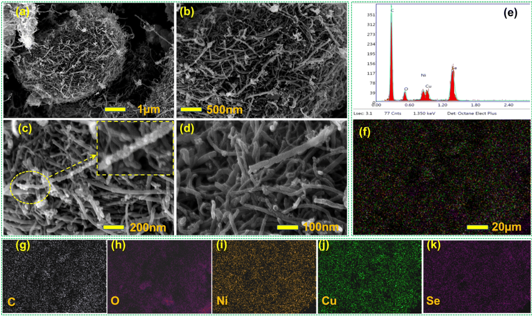 | ||
| Fig. 2 (a)–(d) FESEM images of the CNT-CuNiSe2 at different magnifications. (e) EDX spectrum, (f) EDX elemental mapping, and maps for the corresponding elements (g) C, (h) O, (i) Ni, (j) Cu, and (k) Se. | ||
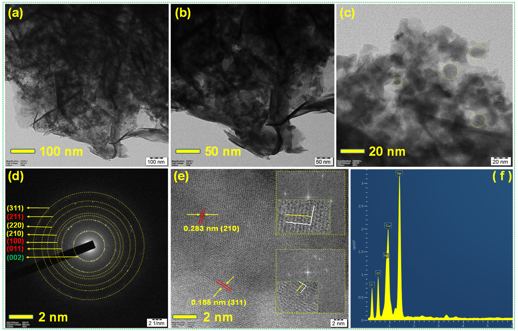 | ||
| Fig. 3 (a), (b) and (c) HRTEM images of the CNT-CuNiSe2 at different magnifications. (d) SEAD pattern of CNT-CuNiSe2. (e) High-resolution image of the CNT-CuNiSe2 composite and corresponding IFFT profiles of lattice spacing shown as insets. (f) EDS analysis of CNT-CuNiSe2. | ||
Further, XPS studies were conducted to describe the electronic arrangements of the CNT-CuNiSe2 composite. The X-ray survey spectrum confirmed the presence of Ni, Cu, Se, O, and C elements at binding energies of 855.54, 932.14, 57.72, 287, and 530.76 eV, respectively, as illustrated in Fig. 1(d). The high-resolution XPS data for Ni 2p, shown in Fig. 1(e), revealed Ni2+ peaks at 854.4 and 871.7 eV, while peaks at 855.7 and 873.4 eV indicated the presence of Ni3+ in CNT-CuNiSe2. Satellite peaks were also observed at 864 and 880 eV for the Ni 2p3/2 and Ni 2p1/2 species, respectively.47Fig. 1(f) displays a high-resolution spectrum of Cu 2p, showing six peaks upon deconvolution. The peaks at 932.66 and 952.55 eV were indicative of the Cu1+ state, while peaks at 934.247 and 954.21 eV corresponded to the Cu2+ state in CNT-CuNiSe2.48 Furthermore, two satellite peaks were detected at 943.27 and 962.79 eV. These findings provide evidenced that the formation of bimetallic selenides and the presence of multiple redox couples contributed to an increased electrochemical storage capacity. The oxidation state of selenium was determined through X-ray photoelectron spectroscopy (XPS) analysis. The spectrum exhibited significant peaks at 54.06, 55.05, 58.75, and 59.59 eV, corresponding to Se3d5/2, Se3d3/2, C–Se, and oxidized S–O, respectively. This indicated that selenium was primarily in the Se2− state, with both bonded and elemental selenium also present, as illustrated in Fig. 1(g).49–51 Additionally, the O 1s spectrum in Fig. 1(h) exhibited peaks at 532.02, 531.01, and 529.77, corresponding to OC–OH, CX (where X = O, Se), and C–O–C, respectively.52 The C 1s XPS spectrum exhibited peaks at 284.85 eV for CC/C–C, 285 eV for C–Se, and 288.96 eV for CX (O, Se), as shown in Fig. 1(i).53 Furthermore, the XPS elemental spectrum (Fig. 1) aligned closely with the EDX elemental data obtained from the SEM analysis (Fig. 2).
SEM and TEM were performed to characterize the materials’ morphology and structure. As shown in the FESEM images in Fig. 2(a) and (d) at various magnifications (ranging from 1 μm to 100 nm), the spherical CuNiSe2 nanoparticles were uniformly distributed over the walls of the MWCNTs, confirming the formation of CNT-CuNiSe2. The carbon nanotubes supported the CuNiSe2 nanoparticles. EDX elemental mapping confirmed the presence of C, O, Ni, Cu, and Se, with peaks shown in Fig. 2(e) and (f). The distribution of elements in the composite is shown in Fig. 2(g)–(k). Further, the ICP-OES analysis was performed to determine the actual contents of Ni, Cu, and Se in the CNT-CuNiSe2 hybrid composite. The result showed that the CNT-CuNiSe2 composite contained Ni (101.2 g kg−1), Cu (102.4 g kg−1), and Se (115.4 g kg−1). The corresponding bar diagram is shown in the ESI (Fig. S1†). Fig. S2(a) and (b)† illustrate the distinct morphologies observed during composite synthesis via in situ synthesis in a single pot, where all the composites were introduced simultaneously under an inert atmosphere. In contrast, physical mixing methods were also explored, wherein MMSe and CNT were combined in a pot without inert conditions and subjected to sonication for the synthesis of CNT-CuNiSe2. In situ synthesis in a single pot demonstrated morphological benefits compared to the physical mixing approach, as supported by the XRD diffraction peaks shown in Fig. S2(c).† The SEM images of CuNiSe2 in Fig. S3(a) and (b)† provide a clear picture of sphere-like nanoparticles and pores in the composite. Similarly, for CNT-NiSe2 and CNT-CuSe2, SEM images were taken in the range of 1 μm to 100 nm and depicted that NiSe2 and CuSe2 were also well distributed, similar to CuNiSe2, in the CNT walls, as shown in Fig. S4(a)–(d) and S5(a)–(d).† No significant morphological changes were observed in the bimetallic selenides and monometallic selenides, as shown in Fig. S6(a) and (b)† for NiSe2.
Next, high-resolution transmission electron microscopy (HRTEM) was utilized for additional morphological analysis, as shown in Fig. 3. The HRTEM images of CNT-CuNiSe2 at various magnifications, as illustrated in Fig. 3(a)–(c), revealed the presence of flat, smooth surfaces and irregular, sphere-like nanoparticles dispersed across the CNT walls, as corroborated by the FESEM images. The sizes of the individual CNT-CuNiSe2 spheres ranged from 11 to 23 nm. Scaled selected area electron diffraction (SAED) images of the spheres were obtained to determine the material phase by measuring the lattice spacing and by comparing the results with standard X-ray diffraction (XRD) data. In Fig. 3(d), the SEAD pattern (002) in green corresponds to the CNT planes (011) and (100), and the (211) in red to CuSe2, while the remaining planes (210), (220), and (311) in yellow are associated with NiSe2. The inverse fast Fourier transform (IFFT) analysis yielded a lattice d spacing value of 0.283 nm for the (210) plane and 0.185 nm for the (311) plane. The EDS of CNT-CuNiSe2 revealed the presence of various elements in this composite, with the results aligning closely with those from the EDS and XPS analyses.
The surface area, pore size, and pore volume are essential factors that can influence the energy-storage performance of a supercapacitor. For instance, hybrid composites typically exhibit an increased surface area, leading to a higher observed capacitance. Furthermore, a composite with a reduced pore size and narrower dimensions will result in a pore volume distribution that enhances the energy density. Thus, choosing a microporous composite is optimal for supercapacitor composites, while a mesoporous structure offers a greater specific surface area. Therefore, hybrid materials that possess both microporous and mesoporous characteristics represent the optimal choice for hybrid supercapacitor composites.54,55
The BET isotherm and porosity of the CNT-CuNiSe2, CNT-NiSe2, and CNT-CuSe2 were analyzed by performing BET N2 adsorption–desorption isotherms, as shown in Fig. 4(a). The surface areas of CNT-CuNiSe2, CNT-NiSe2 and CNT-CuSe2 were 64, 62.27 and 49.15 m2 g−1, respectively. It was observed that the multi-metal CuNiSe2 with CNTs had a greater surface area compared to the monometallic NiSe2 and CuSe2 with CNTs. The DFT method revealed the pore size and pore volume distribution and cumulative surface area of all the three composites, which were shown in Fig. 4(b)–(d). N2 adsorption analysis at 77.350 K under a relative pressure range of 0.0000–1.0000 was performed with the help of the non-local density functional theory (NCDFT) equilibrium model. The analysis indicated that all the composites had a porous nature, with most of the pore volume populated primarily between a 2–25 nm pore width. Among all the composites, CNT-CuNiSe2 exhibited the maximum active surface area with a pore width of ≤5 nm, covering 25 m2 g−1 (≈49%) out of the total active surface area of 51.06 m2 g−1. Meanwhile CNT-NiSe2 covered 27.02 m2 g−1 (≈54.42%) out of 49.08 m2 g−1, while CNT-CuSe2 covered less surface area with a pore width ≤5. Within the ≤25 nm region, CNT-CuNiSe2 possessed 45.2 m2 g−1 (88.52%), but the other two composites showed less surface area in this pore width. These surface area values were found to be nearly equal to those reported in the existing literature.56,57 Furthermore, the combination of both a microporous and mesoporous nature helped CNT-CuNiSe2 to achieve a high specific capacitance. For the percolation and unrestricted flow of ions and substrates at the electrode–electrolyte interface, nanopores with a diameter of less than 5 nm and mesopores with a breadth of less than 25 nm will work well. Thus, the presence of microporosity in CNT-CuNiSe2 could support achieving a higher charge-storage capacity among all the other composites. The active surface area and electrochemical active surface area (EASA) of these materials were calculated by using BET and cyclic voltammetry (CV), respectively. Here, EASA and double layer capacitance (Cdl) were calculated by taking non-faradaic region current values of the voltammograms of three composites which were shown in Fig. S6 (a)–(c).† The plots of the specific current density vs. scan rate for all the electrodes are shown in Fig. S6,† and the double-layer capacitance of each electrode was evaluated from these plots. CNT-CuNiSe2, CNT-NiSe2, and CNT-CuSe2 showed capacitance values of 0.373, 0.285 and 0.1593 mF cm−2, with the results showing that CNT-CuNiSe2 provided a high capacitive value, as depicted in Fig. 4(e). The capacitance values were directly proportional to the EASA, with the EASA calculated using the formula EASA = Cdl/Cs, as shown in Fig. S7.†Fig. 4(f) shows the values for the EASA and BET surface area for the three materials, with CNT-CuNiSe2 showing the highest results in both cases, indicating that it had more surface area available for electrochemical reaction and offered enhanced energy-storage performance.
 | ||
| Fig. 4 (a) BET isotherms of CNT-CuNiSe2, CNT-NiSe2, and CNT-CuSe2. (b–d) Plots of the cumulative surface area versus pore volume against the pore distribution. (e) Double-layer capacitances of the composites from non-faradaic CV after linear fitting. (f) BET surface area plot against the EASA of all three composite materials. | ||
3.2. Electrochemical characterization
Before developing the hybrid supercapacitor, we assessed the supercapacitive performance of the synthesized samples using a three-electrode cell configuration. This assessment sought to validate the suitability of our materials for their intended application in supercapacitor devices. It has been reported that the specific conductivity of a 6 M KOH solution (62.66 × 10⁻² S cm−1) surpasses that of lower concentrations (1 to 5 M), demonstrating enhanced effectiveness for improving supercapacitive properties.55,56 Consequently, 6 M KOH solution was chosen as the electrolyte for this investigation, and concentrations exceeding 6 M were intentionally avoided due to their tendency to cause the aggregation of electroactive materials from the electrode surface.56 Initially, the electrochemical studies were done for MMSe, such as CuNiSe2, and MSe, such as NiSe2 and CuSe2. The studies depicted that CuNiSe2 showed better electrochemical activity in the CV analysis, as presented in Fig. S8(a),† and a higher charge-storage capacity as the discharge time was higher in the GCD analysis, whereas NiSe2 and CuSe2 displayed a lower current density and lower discharge time, as shown in Fig. S8(b).† Before conducting the electrochemical analysis of CNT-CuNiSe2, CNT-NiSe2, and CNT-CuSe2, the study also examined the electrochemical performance of Cu1−XNiXSe2 with various molar ratios of Cu and Ni, without the presence of CNTs. Cyclic voltammetry at 20 mV within the range of −0.2 to 0.65 V was conducted, revealing that equimolar ratios of Cu and Ni yielded the highest current density, as illustrated in Fig. 5(a). Additionally, multiple redox couple behaviours were noted across all cases, with the intensity of Cu0.5Ni0.5Se2 exhibiting the highest peak current. Additionally, the charge and discharge times of Cu0.5Ni0.5Se2 were improved in the GCD analysis, as illustrated in Fig. 5(b). This finding was strongly corroborated by the CV investigation, which ruled out all other composites except Cu0.5Ni0.5Se2. To enhance the electrochemical performance, carbon nanotubes were incorporated into Cu0.5Ni0.5Se2, NiSe2, and CuSe2, resulting in the composite CNT-CuNiSe2, CNT-NiSe2, and CNT-CuSe2. Cyclic voltammetry was next conducted to assess their electrochemical behaviour, with the corresponding CV profiles analyzed at 20 mV s−1 within the range of −0.2 V to 0.65 V. CNT-CuNiSe2 exhibited the highest peak current and a significantly larger enclosed area in the graph compared to all the other electrodes, as indicated by the green peaks in Fig. 5(c). The charge-storage phenomenon was further supported by this discovery, which verified its quasi-reversible redox function. For extra proof, the GCD profile of every electrode was measured at 1 A g−1. As shown in Fig. 5(d), the CNT-CuNiSe2 discharge duration was noticeably greater than that of CNT-NiSe2, CNT-CuSe2, CuNiSe2, NiSe2, and CuSe2. | ||
| Fig. 5 (a) Comparison of cyclic voltammograms of different compositions of Cu1−XNiXSe2 at 20 mV scan rate. (b) Charging and discharging (GCD) measurements of Cu1−XNiXSe2 at 1 A g−1. (c) and (d) Comparison of the CV curves at a 20 mV scan rate and GCD with current densities from 1 to 32 A g−1 for CuNiSe2, NiSe2, and CuSe2, including CNT-CuNiSe2, CNT-NiSe2, and CNT-CuSe2 at various current densities. | ||
Additionally, three-electrode configurations were used to evaluate CNT-CuSe2, CNT-NiSe2, and CNT-CuNiSe2 in 6 M KOH solution. According to the results of this study, CNT-CuNiSe2 exhibited superior electrochemical performance for the hybrid SC materials. For the CNT-CuSe2 and CNT-NiSe2 electrodes that were first created and evaluated, Fig. 6(a) and (b) show that CNT-CuSe2 had a lower current density and a shorter discharge time; whereas CNT-NiSe2 showed a sharp, higher peak current and long discharging time, as present in Fig. 6(c) and (d), due to its more active surface area, as revealed by the BET studies.
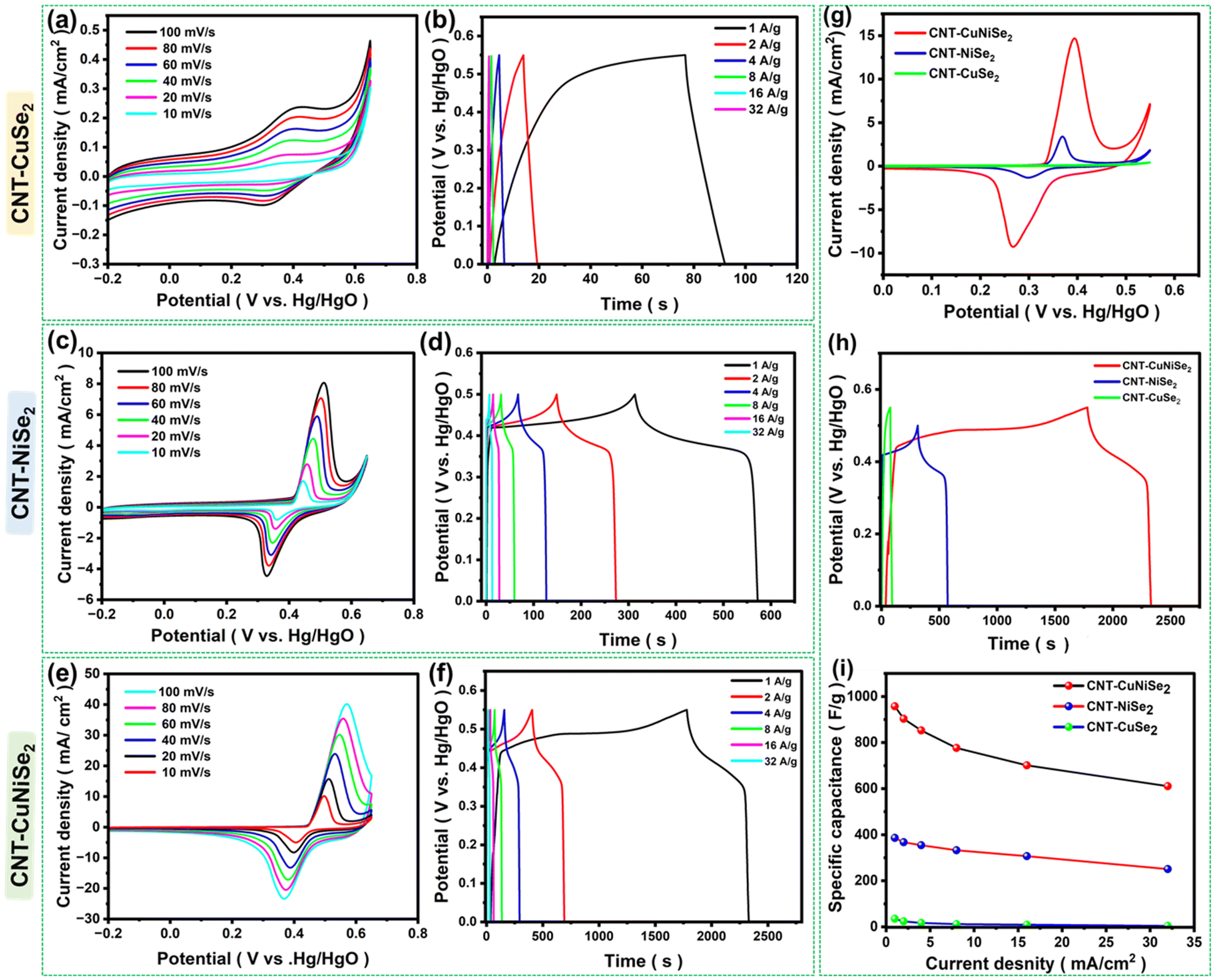 | ||
| Fig. 6 (a) and (b) CVs and GCD of CNT-CuSe2 at different scan rates and various current densities from 1 to 32 A g−1. (c), (d), (e) and (f) CVs and GCD of CNT-NiSe2, CNT-CuNiSe2 electrodes in 4 M KOH solution from 10 to 100 mV scan rates and at different current densities. (g) CV patterns of CNT-CuNiSe2, CNT-NiSe2, and CNT-CuSe2 at 20 mV. (h) Comparison of the GCD at 1 A g−1 for CNT-CuNiSe2, CNT-NiSe2, and CNT-CuSe2 electrodes. (i) Specific capacitance vs. current densities for the CNT-CuNiSe2, CNT-NiSe2, and CNT-CuSe2 electrodes. | ||
It is worth noting that CNT-CuNiSe2 exhibited a larger CV integrated peak area and higher and broader redox intensity peak in Fig. 6(e), due to its multiple redox couples, such as Cu+/Cu2+ and Ni2+/Ni3+, with eqn (1)–(3) indicating that higher capacity values could be expected from CNT-CuNiSe2.58,59
| CuNiSe2 + 2OH− → CuSe2OH + NiSe2OH + 2e− | (1) |
| CuSe2OH + OH− → CuSe2O + H2O + e− | (2) |
| NiSe2OH + OH− → NiSe2O + H2O + e− | (3) |
The fast movement of electrons and ions at the interface between CNT-CuNiSe2 and KOH was indicated by the notable rise in the current density of all the CVs between 10 and 100 mV s−1. In addition, Fig. 6(f) shows that the discharge time of CNT-CuNiSe2 was much longer than that of CNT-NiSe2 and CNT-CuSe2, suggesting that CNT-CuNiSe2 performed better in terms of specific capacity. Fig. 6(g) shows the comparison of the CV curves all three electrodes at 20 mV s−1. When examined at 1 A g−1 in Fig. 6(h), the GCD patterns of CNT-CuNiSe2, CNT-NiSe2, and CNT-CuSe2 showed prolonged charge and discharge times. The GCD profiles were used to measure the specific capacitance (Cs) using eqn (4).
| Cs = (I × dt)/m × dV | (4) |
Upon analysis at 1, 2, 4, 8, 16, and 32 A g−1, the Cs values of CNT-CuNiSe2 were 957.06, 902.87, 852.86, 776.47, 700.96 and 610.56 F g−1, respectively. Further, the same values were 385.96, 367.077, 354.37, 332.25, 306.78 and 250.59 F g−1, respectively, for CNT-NiSe2. Lastly, measurements of the Cs of CNT-CuSe2 revealed that they were 34.73, 23.78, 16.63, 11.75, 9.5 and 4.2 F g−1, respectively. Fig. 6(i) displays plots of the Cs values of all three materials against various current densities. Because of their superior electrical conductivity, CNTs may help lower the internal resistance, as shown by the enhanced electrochemical activity. CNTs are notable for their abundance of charge-transfer routes, which can speed up Faraday redox reactions.
3.3. Two-electrode hybrid symmetric supercapacitor devices
The storage capabilities of the synthesized CNT-CuSe2, CNT-NiSe2, and CNT-CuNiSe2 materials, which were coated onto conducting carbon cloth to form electrodes, were evaluated. The resulting configurations, namely, CC/CNT-CuSe2, CC/CNT-NiSe2, and CC/CNT-CuNiSe2, were assembled with a separator and immersed in 6 M KOH, and designated as CC/CNT-CuSe2//CC/CNT-CuSe2, CC/CNT-NiSe2//CC/CNT-NiSe2, and CC/CNT-CuNiSe2//CC/CNT-CuNiSe2, respectively. The symmetric electrodes were examined within an airtight flat cell holder to mitigate air contamination and exposure. The CV optimization was documented at various scan rates. The optimal potential windows for the hybrid symmetric electrodes, i.e., CC/CNT-CuSe2//CC/CNT-CuSe2, CC/CNT-NiSe2//CC/CNT-NiSe2, and CC/CNT-CuNiSe2//CC/CNT-CuNiSe2, were determined to be 0 to 1.1 V, 0 to 1.4 V, and 0 to 1.5 V, respectively. The cyclic voltammograms at varying scan rates are presented in Fig. 7(a), (c) and (e). The GCD profiles for all three electrodes were analyzed at varying current densities, as illustrated in Fig. 7(b), (d) and (f). Fig. 7(g) compares the CV profiles for all electrodes at a scan rate of 20 mV s−1. | ||
| Fig. 7 (a), (c) and (e) CVs (b), (d) and (f) GCD profiles of (a) and (b) CC/CNT-CuSe2//CC/CNT-CuSe2, (c) and (d) CC/CNT-NiSe2//CC/CNT-NiSe2 and (e) and (f) CC/CNT-CuNiSe2//CC/CNT-CuNiSe2. (g) CV difference of the HSCs at a 20 mV scan rate. (h) GCD profile of all the HSCs at 1 A g−1. (i) Comparison of the Cs of CC/CNT-CuNiSe2//CC/CNT-CuNiSe2, CC/CNT-NiSe2//CC/CNT-NiSe2 and CC/CNT-CuSe2//CC/CNT-CuSe2 at varying current densities. | ||
The CC/CNT-CuNiSe2//CC/CNT-CuNiSe2 electrode gives the highest background current with redox peaks compared to the two other electrodes. The resulting peaks revealed that the composite contained both EDLC and pseudo-capacitor behaviours. This was attributed to the contributions from both the cathode (CC/CNT-CuNiSe2) and anode (CC/CNT-CuNiSe2) materials. Significantly, even with elevating the sweep rate, the integrity of the graphs was maintained, underscoring the device's reversibility and strong electrochemical characteristics. The GCD profiles of the symmetric cells gave quasi-rectangular shapes, and the GCD patterns were compared at 1 A g−1, as shown in Fig. 7(h). CC/CNT-CuNiSe2//CC/CNT-CuNiSe2 provided lower Ohmic drops, and the Cs values of all three cells were calculated using eqn (5)
| Cs = (2 × (i/m) × Δt)/ΔV. | (5) |
The Cs values of the CC/CNT-CuNiSe2//CC/CNT-CuNiSe2 cell were measured as 265.586, 209.022, 167.72, 112.0236, 39.68 and 4.096 F g−1 at 1, 2, 4, 8, 16, and 32 A g−1. The Cs values of the CC/CNT-NiSe2//CC/CNT-NiSe2 cell were as follows: 88.176, 75.057, 38.4, 12.16, 2.4, and 1.4 F g−1. Finally, the Cs of the CC/CNT-CuSe2//CC/CNT-CuSe2 cell exhibited values of 74.028, 26.092, 4.834, 2.16, 0.9262, and 0.884 F g−1, respectively.
The Cs values of the devices were plotted against the current densities, as shown in Fig. 7(i). At all current densities, the Cs values of the CC/CNT-CuNiSe2//CC/CNT-CuNiSe2 device were shown to be three times greater than those of the CC/CNT-NiSe2//CC/CNT-NiSe2 and CC/CNT-CuSe2//CC/CNT-CuSe2 devices. It was observed that the Cs values of all devices consistently decreased from lower to higher current densities. Increased specific currents reduce the capacitance as they impede the movement of OH-ions to the surface, thereby decreasing ion penetration into the electrode's inner regions and elevating the Ohmic resistance. Next, Ed and Pd were evaluated using eqn (6) and (7), and the corresponding Rangone plot is shown in Fig. 7(b).
| Ed (W h kg−1) = (CS × ΔV2 × 1000)/7200 | (6) |
| Pd (W kg−1) = (3600 × Eden)/Δt | (7) |
Here, Ed is energy density, Pd is the power density, Δt is the difference from the discharge time, and ΔV is the potential window.
The performance of CC/CNT-CuNiSe2//CC/CNT-CuNiSe2, CC/CNT-NiSe2//CC/CNT-NiSe2, and CC/CNT-CuSe2//CC/CNT-CuSe2 symmetric devices were assessed, and they exhibited high Ed and Pd values. The CC/CNT-CuNiSe2//CC/CNT-CuNiSe2 device delivered 82.99 W h kg−1 at 1511.35 W kg−1 (1 A g−1) and 1.28 W h kg−1 at 48000 W kg−1 (32 A g−1). Whereas, the CC/CNT-NiSe2//CC/CNT-NiSe2 and CC/CNT-CuSe2//CC/CNT-CuSe2 devices delivered 24.0, 12.44 W h kg−1 at 1399.92, 1099.84 W kg−1 (1 A g−1) and 0.381, 0.148 W h kg−1 at 44129.02, 38057.14 W kg−1 (32 A g−1). In comparison to CC/CNT-NiSe2//CC/CNT-NiSe2 and CC/CNT-CuSe2//CC/CNT-CuSe2, the CC/CNT-CuNiSe2//CC/CNT-CuNiSe2 device showed significantly high Ed and Pd values, and its energy-storage performance was better than the reported literature data, as presented in Table 1.
| Electrode material | Specific capacitance | Energy density (W h kg−1) | Power density (W kg−1) | Cyclic stability | C s retention | Ref. |
|---|---|---|---|---|---|---|
| CoNi-Se/rGO | 2957 F g−1 | 73 | 1500 | 20000 |
83% | 58 |
| Co-NiSe2/MXene | 1394.8 F g−1 | 20 | 684 | 5000 | 67% | 60 |
| CF/Cu2S@Cu3Se2/P | 1099 C g−1 | 41.1 | 480.4 | 10000 |
90.2% | 61 |
| Co–Ni–Se/BWCF-160 | 3050 F g−1 | 49.7 | 1052 | 5000 | 93.3% | 62 |
| 3DG/ZnSe−SnSe2 | 1515.2 F g−1 | 25.3 | 750 | 20000 |
91.3% | 63 |
| Cu7Se4-CuxCo1−xSe2 | 349.1 F g−1 | 26.84 | 700 | 5000 | 94.1% | 64 |
| Ni2CoS4@(NiCo)Se2 | 6054 mF cm−2 | 53 | 480 | 10000 |
84.0% | 37 |
| ZnSe/MnSe | 1439.98 F g−1 | 56.17 | 265 | 5000 | 65 | |
| NiMoSe2 | 480 F g−1 | 44.04 | 2000.1 | 15000 |
99.4% | 66 |
| rGO-MnSe2/CoSe2 | 1214 F g−1 | 49.7 | 888 | 5000 | 88% | 67 |
| CNT-CuNiSe2 | 957.06 F g−1 | 82.99 | 1511.35 | 6000 | 101.3% | This work |
The stability study of the CC/CNT-CuNiSe2//CC/CNT-CuNiSe2 hybrid symmetric device was done at 4 A g−1 for 6000 consecutive GCD cycles. The device's specific capacitance retention and coulombic efficiency were plotted as a function of the cycles in Fig. 8(c) and (d). At the end of 6000 cycles of charge and discharge at a higher current density, the CC/CNT-CuNiSe2//CC/CNT-CuNiSe2 device delivered a Cs of 101.3% with a coulombic efficiency of 93.63%, as measured using Equation S2. Initially, there was an increase in the capacitance of 115%, up to 1500 cycles. After 1500 cycles, the Cs became stable, and it was constant, with not much loss in Cs, which was projected to be 101.3% at the end of 4000 cycles. There was no loss in Cs observed up to 6000 cycles; however, since there was no proper wettability between the electrode and electrolyte at the beginning, fluctuations in specific capacitance may occur during the continuous cycling. Importantly, due to the participation of all the electrode materials at the start of the cycles, after certain periods, the degradation of the material can occur, which may lead to structural morphology changes. The comprehensive analysis of the CS, Pd, Ed, and long cycle durability of CC/CNT-CuNiSe2//CC/CNT-CuNiSe2 demonstrated significant support and enhancement, resulting in an effective electrochemical hybrid supercapacitor cell. Furthermore, the CC/CNT-CuNiSe2//CC/CNT-CuNiSe2 HSC device was used to power a commercial light emitting diode (LED), which could be charged to 1.5 V, as shown in Fig. 8(e), confirming the potential use of device in a real-world application. The post-characterization of the HSD materials was performed by FESEM and XRD, as shown in Fig. S9 (a)–(d).† The result revealed that there was no significant morphological or structural changes compared to HSC materials before the long-time GCD analysis. Further, the self-discharging behaviour of the HSC was assessed after charging to 1.5 V, assuming that the relaxing phenomena had time constants of less than 1 h. Consequently, when the charging current was stopped, the decrease in voltage across the supercapacitor was only from the effect of self-discharge. Fig. S10† shows the self-discharge of the aforementioned supercapacitor at an ambient temperature of 25 °C and for an initial voltage of 1.5 V. It was observed that the device showed a 0.4 V loss after 5000 s and the device decay stabilized at 1.1 V, with less self-discharge. The performance of the device thus showed its suitability for use in energy-storage applications.
 | ||
| Fig. 8 (a) Graphical representation of the two-electrode system. (b) Specific energy versus specific power plots of the HSCs. (c) Cs retention of the symmetric SC CC/CNT-CuNiSe2//CC/CNT-CuNiSe2; inset shows the initial and final GCD consecutive cycles of 6000 cycles of GCD at 4 A g−1. (d) Coulombic efficiency of HSC over the period of 6000 cycles. (e) Electrochemical impedance spectra of all three HSCs in 6 M KOH solution. (f) CC/CNT-CuNiSe2//CC/CNT-CuNiSe2-powered HSC device illuminating a 1 V LED. | ||
3.4. Electrochemical impedance spectroscopy (EIS)
EIS was performed to analyze all three electrodes, as shown in Fig. S8† and in the photos of the symmetric device in Fig. 8(f), from 0.01 Hz to 105 Hz, and the results were best fitted with the basic Randles circuit, as shown in Fig. S11† (inset) and Fig. 8(f inset). The Rct, Rs, and W values of CNT-CuNiSe2 were 0.1279 mΩ, 13.8 Ω, and 0.00072 Ω; while for CNT-NiSe2, the values were 0.135 mΩ, 14.2 Ω, and 0.00082 Ω. Finally, the CNT-CuSe2 electrodes had values of 15.57 Ω, 0.143 mΩ, and 0.011 Ω, respectively. Similarly, EIS analysis was carried out for CC/CNT-CuSe2//CC/CNT-CuSe2 (17.4 Ω, 0.9713 Ω and 0.0334 Ω), CC/CNT-NiSe2//CC/CNT-NiSe2 (8.04 Ω, 0.6791 Ω and 0.04015 Ω) and CC/CNT-CuNiSe2//CC/CNT-CuNiSe2 (2.359 Ω, 0.6047 Ω and 0.03579 Ω) devices. It was observed that the CC/CNT-CuNiSe2//CC/CNT-CuNiSe2 device exhibited low resistance parameters. From this study, it is evident that CC/CNT-CuNiSe2//CC/CNT-CuNiSe2 SC had effectively low Rct, Rs, and W values, which are favourable for enhanced charging and discharging of the SC, thus increasing the coulombic efficiency.4. Conclusions
We successfully synthesized CNT-modified bimetallic CuNiSe2 through an in situ reaction in a one-pot process utilizing liquid-phase reduction method, which is an efficient and cost-effective approach for the development of bimetallic selenides as energy-storage device materials. We believe this method significantly enhances the electrochemical performance using the one-pot synthesis protocol. In addition, this synthesis procedure helps form uniform CuNiSe2 nanoparticles distributed over the walls of the CNTs, maintaining the synergistic benefits from the pi-cloud of the carbon nanotubes. As a result, increases in high electrochemical storage performance and the unique faradaic characteristics have been observed in cyclic voltammetry and charge–discharge behavior analyses, including excellent electrical conductivity of the aqueous electrolyte and redox activity, leading to an enhanced specific capacitance of 957.06 F g−1 at a current density of 1 A g−1 for the CNT-CuNiSe2 electrode. The CC/CNT-CuNiSe2//CC/CNT-CuNiSe2 HSC demonstrated a capacitance of 265.586 F g−1 at 1 g−1, achieving a capacitance retention of 101.3% and a coulombic efficiency of 93.63% after 6000 GCD cycles. The constructed CC/CNT-CuNiSe2 HSC exhibited remarkable performance, reaching a high energy density of 82.99 W h kg−1 alongside a power density of 1511.35 W kg−1, with the capability to operate in the potential range of 0 to1.5 V. Creating these materials using economical and eco-friendly methods would greatly benefit energy-storage applications in both industrial and commercial sectors.Author contributions
The manuscript was written with contributions from all authors, and all authors have approved the final version of the manuscript.Data availability
Data files can be shared upon reasonable request.Conflicts of interest
The authors declare that there are no financial interests or personal relationships that could have influenced the work presented in this paper.Acknowledgements
Soumyajit Jana and K. Yugender Goud would like to express their gratitude to the Department of Science and Technology, Science and Engineering Research Board (DST-SERB/RJF/2021/000113, Ramanujan Award), New Delhi, India, and the Indian Institute of Technology Palakkad, Seed Grant Project (2024-254-CHY-YGK-SGP-SP) for their financial support and research facilities. The authors also acknowledge the Central Instrumentation Facility at IIT Palakkad for chemical and material characterizations, as well as the SRM Central Instrumentation Facility (SCIF) for TEM characterization. The ToC and Fig. 8a were created with Blender via Blender Foundation and VESTA (K. Momma and F. Izumi, “VESTA 3 for three-dimensional visualization of crystal, volumetric and morphology data,” J. Appl. Crystallogr., 2011, 44, 1272–1276).References
- A. Russo, M. Costanzo and A. Cavallo, 2022 5th Int. Conf. Mechatronics, Robot. Autom. ICMRA 2022, 2022, 64–68.
- Y. Liu, S. P. Jiang and Z. Shao, Mater. Today Adv., 2020, 7, 100072 CrossRef.
- C. Zhong, Y. Deng, W. Hu, J. Qiao, L. Zhang and J. Zhang, Chem. Soc. Rev., 2015, 44, 7484–7539 RSC.
- Z. Lin, E. Goikolea, A. Balducci, K. Naoi, P. L. Taberna, M. Salanne, G. Yushin and P. Simon, Mater. Today, 2018, 21, 419–436 CrossRef CAS.
- S. Karingula, S. Kumari, Y. Goud Kotagiri, L. Malyala and K. Vengatajalabathy Gobi, Small, 2025, 21, 2408899 CrossRef CAS PubMed.
- H. Jabraoui, D. Pech, M. D. Rouhani, C. Rossi and A. Esteve, J. Energy Storage, 2024, 98, 112926 CrossRef.
- S. Mothkuri, S. Chakrabarti, H. Gupta, B. Padya, T. N. Rao and P. K. Jain, Mater. Today: Proc., 2018, 26, 142–147 Search PubMed.
- T. Hao, Y. Liu, G. Liu, C. Peng, B. Chen, Y. Feng, J. Ru and J. Yang, Energy Storage Mater., 2019, 23, 225–232 CrossRef.
- L. Kang, S. Liu, Q. Zhang, J. Zou, J. Ai, D. Qiao, W. Zhong, Y. Liu, S. C. Jun, Y. Yamauchi and J. Zhang, ACS Nano, 2024, 18, 2149–2161 CrossRef CAS PubMed.
- H. S. Shahidani, M. Seifi and M. Bagher Askari, Inorg. Chem. Commun., 2024, 170, 113218 CrossRef CAS.
- C. Miao, X. Xiao, Y. Gong, K. Zhu, K. Cheng, K. Ye, J. Yan, D. Cao, G. Wang and P. Xu, ACS Appl. Mater. Interfaces, 2020, 12, 9365–9375 CrossRef CAS PubMed.
- C. Lu, Y. Yang, S. Li and M. Zhu, Mater. Chem. Front., 2024, 8, 2282–2292 RSC.
- M. Aman, V. Sharma and S. Omar, Appl. Surf. Sci., 2024, 670, 160611 CrossRef CAS.
- Y. Dong, T. Li, H. Su, X. Zhang and J. Zhang, J. Hazard. Mater., 2024, 477, 135281 CrossRef CAS PubMed.
- K. Zhang, Y. Li, S. Deng, S. Shen, Y. Zhang and G. Pan, ChemElectroChem, 2019, 3530–3548 CrossRef CAS.
- Y. Gu, Y. Katsura, T. Yoshino, H. Takagi and K. Taniguchi, Sci Rep., 2015, 1–9 Search PubMed.
- N. S. Arul and J. I. Han, Mater. Lett., 2016, 181, 345–349 CrossRef CAS.
- G. P. Patil, C. D. Jadhav, S. Lyssenko, A. Borenstein and R. Minnes, J. Mater. Chem. C, 2024, 14404–14420 RSC.
- T. Chen, S. Li, J. Wen, P. Gui, Y. Guo, C. Guan, J. Liu and G. Fang, Small, 2018, 14, 1–8 Search PubMed.
- M. Amiri, A. Mohammadi Zardkhoshoui, S. S. Hosseiny Davarani, M. Maghsoudi and M. K. Altafi, Sustainable Energy Fuels, 2022, 6, 3626–3642 RSC.
- Z. Li, M. Tian, Y. Chen, Y. Liu, Y. Cai and W. Wei, Ceram. Int., 2021, 47, 12623–12630 Search PubMed.
- Y. Yang, L. Liu, S. Li and M. Zhu, ACS Appl. Energy Mater., 2024, 7, 7307–7315 CrossRef CAS.
- M. Molaei, M. Abdollahi, A. M. Zardkhoshoui and S. S. H. Davarani, J. Energy Storage, 2024, 85, 111079 CrossRef.
- Q. Lu, T. Zhou, M. Chen, J. Zhao, H. Sun, B. Li, B. Zi, J. Zhang, Z. Zhu and Q. Liu, ACS Energy Lett., 2024, 145–155 Search PubMed.
- G. Zhang, H. Xuan, J. Yang, R. Wang, Z. Xie, X. Liang, P. Han and Y. Wu, J. Power Sources, 2021, 506, 230255 CrossRef CAS.
- S. H. Lee, J. H. Kim and J. R. Yoon, Sci. Rep., 2018, 8, 1–9 CrossRef.
- Y. Yang, Y. Ma, C. Lu, S. Li and M. Zhu, Green Chem., 2023, 25, 10209–10234 RSC.
- B. Liu, Y. Ye, M. Yang, Y. Liu, H. Chen, H. Li and W. Fang, Adv. Funct. Mater., 2024, 2310534, 1–10 Search PubMed.
- B. Liu, L. Zhao, Y. Liu, H. Chen, H. Li, M. Yang and J. Qiu, Adv. Mater., 2025, 2419124, 1–10 Search PubMed.
- H. Ding, S. Zhao, X. Wang, C. Qian, T. Zou, X. Li, H. Li, F. Jiang, Y. Liu, H. Cao, Z. Fang and Y. Zhu, Colloids Surf., A, 2023, 668, 131462 CrossRef CAS.
- Y. Peng, M. Wei, D. Zhang, X. Liu, X. Xiong, W. Gao, W. Fan, H. Yang, Q. Zhou, T. Wang, F. Wang, Y. Ma, Y. Zhong, X. B. Cheng, Z. Zhu, J. He and Y. Wu, Nano Energy, 2024, 130, 110077 Search PubMed.
- M. Liu, J. Xu, L. Shao, X. Shi, C. Li and Z. Sun, Chem. Commun., 2024, 60, 6860–6872 RSC.
- G. Li, Y. Tang, S. Cui, H. Chen, H. Chong and L. Han, Adv. Funct. Mater., 2024, 2401586, 1–10 Search PubMed.
- B. G. Amin, J. Masud and M. Nath, RSC Adv., 2019, 37939–37946 RSC.
- J. Yan, L. Rasenthiram, H. Fang, R. Tjandra, L. Wang, L. Wang and Y. Zhang, Ionics, 2019, 675–683 Search PubMed.
- N. Bibi, Y. Xia, S. Ahmed, Y. Zhu, S. Zhang and A. Iqbal, Ceram. Int., 2018, 44, 22262–22270 Search PubMed.
- L. Duan, H. Fu, H. Guo, H. Sun, Q. Zhang, J. Xu and J. Liu, Appl. Surf. Sci., 2024, 648, 158966 CrossRef CAS.
- A. Ullah, K. Tahir, H. M. A. Hassan, K. Albalawi, Q. Ullah, A. Khan, M. M. Moharam, S. Latif, M. S. Refat and A. Mohammed, J. Electroanal. Chem., 2022, 920, 116624 CrossRef.
- S. Hussain, M. Sufyan, S. Asim, A. Shaheen, A. Jabbar, Y. Abbas, N. Ullah, A. Iqbal, M. Wang, G. Qiao and S. Yun, Ceram. Int., 2020, 46, 6406–6412 CrossRef CAS.
- Y. Lu, X. Liu, W. Wang, J. Cheng, H. Yan, C. Tang, J. K. Kim and Y. Luo, Sci. Rep., 2015, 5, 1–11 Search PubMed.
- H. Charles, P. J. Chengula, H. Oh and C. S. Lee, Surf. Interfaces, 2024, 52, 104838 CrossRef CAS.
- H. Li, H. Zu, Q. Li, J. Yang, W. Qu and Z. Yang, Environ. Sci. Technol., 2022, 56, 575–584 CrossRef CAS PubMed.
- B. Jansi Rani, G. Ravi, R. Yuvakkumar, B. Saravanakumar, M. Thambidurai, C. Dang and D. Velauthapillai, ACS Omega, 2020, 5, 14702–14710 CrossRef CAS PubMed.
- M. Farbod, S. K. Tadavani and A. Kiasat, Colloids Surf., A, 2011, 384, 685–690 CrossRef CAS.
- Z. Li, X. Ma, L. Wu, H. Ye, L. Li, S. Lin, X. Zhang, Z. Shao, Y. Yang and H. Gao, RSC Adv., 2021, 11, 6842–6849 Search PubMed.
- W. Zhang, W. Yang, H. Zhou, Z. Zhang, M. Zhao, Q. Liu, J. Yang and X. Lu, Electrochim. Acta, 2020, 357, 136855 CrossRef CAS.
- P. A. Shinde, N. R. Chodnakar, Mohammad A. Abdelkarrem, Swati J. Patil, Y. K. Han, K. Elsaid and A. G. Olabi, Small, 2022, 18, 2200248 CrossRef CAS PubMed.
- T. Li, Q. Zhang, X. H. Wang, J. Luo, L. Shen, H. C. Fu, F. Gu, N. B. Li and H. Q. Luo, Nanoscale, 2021, 13, 17846–17853 RSC.
- F. Ming, H. Liang, H. Shi, X. Xu, G. Mei and Z. Wang, J. Mater. Chem. A, 2016, 4, 15148–15155 RSC.
- S. Karingula, S. Kumari, Y. Goud Kotagiri and K. Vengatajalabathy Gobi, Small, 2024, 2400812 CrossRef CAS PubMed.
- J. Zhou, M. Chen, T. Wang, S. Li, Q. Zhang, M. Zhang, H. Xu, J. Liu, J. Liang, J. Zhu and X. Duan, iScience, 2020, 23, 100919 CrossRef CAS PubMed.
- Q. Han, W. Zhang, L. Zhu, M. Liu, C. Xia, L. Xie, X. Qiu, Y. Xiao, L. Yi and X. Cao, ACS Appl. Mater. Interfaces, 2024, 16, 6033–6047 CrossRef CAS PubMed.
- F. Jin, M. Li, L. Xie and J. Jiang, J. Power Sources, 2021, 514, 230587 CrossRef CAS.
- S. Kondrat, C. R. Pérez, V. Presser, Y. Gogotsi and A. A. Kornyshev, Energy Environ. Sci., 2012, 5, 6474–6479 RSC.
- A. Iakunkov, V. Skrypnychuk, A. Nordenström, E. A. Shilayeva, M. Korobov, M. Prodana, M. Enachescu, S. H. Larsson and A. Vtalyzin, Phys. Chem. Chem. Phys., 2019, 21, 17901–17912 RSC.
- Z. Andikaey, A. A. Ensafi, B. Rezaei and J. S. Hu, Electrochim. Acta, 2022, 417, 140338 CrossRef CAS.
- Q. Wang, X. Tian and D. Zhang, Matlet., 2020, 276, 8–11 Search PubMed.
- E. Aboelazm, C. S. Khe, K. F. Chong, M. S. Mohamed Saheed and M. B. Z. Hegazy, ACS Appl. Mater. Interfaces, 2024, 16, 15011–15022 CrossRef CAS PubMed.
- J. Balamurugan, T. T. Nguyen, V. Aravindan, N. H. Kim, S. H. Lee and J. H. Lee, Nano Energy, 2019, 65, 103999 CrossRef CAS.
- M. Patel, S. Patel, K. Mahabari, R. Mohili, A. H. Jadhav, M. Sharma, K. Lee and N. K. Chaudhari, ACS Appl. Nano Mater. 2024728172–28185 Search PubMed.
- H. Fu, A. Zhang, H. Guo, L. Duan, F. Jin, H. Zong, X. Sun and J. Liu, ACS Appl. Mater. Interfaces, 2023, 15, 8169–8180 CrossRef CAS PubMed.
- M. Gao, Y. Xue, Y. Zhang, C. Zhu, H. Yu, X. Guo, S. Sun, S. Xiong, Q. Kong and J. Zhang, Inorg. Chem. Front., 2022, 9, 3933–3942 RSC.
- T. Zhao, G. Feng, L. Zhou, X. Wang, X. Li, F. Jiang, H. Li, Y. Liu, Q. Yu, H. Cao, Y. Xu and Y. Zhu, ACS Appl. Nano Mater., 2024, 7, 13434–13446 CrossRef CAS.
- X. Yang, X. Chen, H. Cao, C. Li, L. Wang, Y. Wu, C. Wang and Y. Li, J. Power Sources, 2020, 480, 228741 CrossRef CAS.
- M. Hussain, B. M. Alotaibi, A. W. Alrowaily, H. A. Alyousef, M. F. Alotiby, M. Abdullah, A. G. Al-Sehemi, A. M. A. Henaish, Z. Ahmad and S. Aman, J. Phys. Chem. Solids, 2024, 188, 111919 CrossRef CAS.
- J. J. J. J. Kamaraj, P. Annamalai, S. Perumal, S. P. Muthu and R. Perumalsamy, J. Energy Storage, 2023, 73, 109262 CrossRef.
- T. S. Krishnan, P. S. Babu, M. Praveen and V. Janakiraman, J. Electron. Mater., 2024, 53, 5273–5285 CrossRef CAS.
Footnotes |
| † Electronic supplementary information (ESI) available: In situ synthesis versus physical mixing synthesis, along with their corresponding XRD and FESEM images of CuNiSe2, CNT-NiSe2, CNT-CuSe2, NiSe2, EASA calculations, a table comparing Cdl, Cs, and EASA, CV of the three composites at different scan rates, and EIS plots of all the electrodes. See DOI: https://doi.org/10.1039/d5nr00340g |
| ‡ Equal contribution. |
| This journal is © The Royal Society of Chemistry 2025 |