
 Open Access Article
 This Open Access Article is licensed under a
 Creative Commons Attribution 3.0 Unported Licence
Magnetic field-assisted nanochain formation of intermixed catalytic Co–Pd nanoparticles
Calle
Preger
 *abc,
Lisa
Rämisch
d,
Johan
Zetterberg
d,
Sara
Blomberg
ce and
Maria E.
Messing
*cf
*abc,
Lisa
Rämisch
d,
Johan
Zetterberg
d,
Sara
Blomberg
ce and
Maria E.
Messing
*cf
aDivision of Ergonomics and Aerosol Technology, Lund University, 22100 Lund, Sweden. E-mail: calle.preger@maxiv.lu.se
bMAX IV Laboratory, Lund University, 22100 Lund, Sweden
cNanoLund, Lund University, 22100, Lund, Sweden. E-mail: maria.messing@ftf.lth.se
dDivision of Combustion Physics, Lund University, 22100 Lund, Sweden
eDepartment of Process and Life Science Engineering, Sweden
fDivision of Solid State Physics, Lund University, 22100 Lund, Sweden
First published on 21st November 2024
Abstract
Engineering on the nanoscale often involves optimizing performance by designing and creating new types of nanostructured materials. Multifunctional nanoparticles can be formed by combining elements that carry fundamentally different properties. The elements can be chosen based on the desired functionality, and by combining, e.g., magnetic, and catalytic elements, it is possible to self-assemble nanoparticles into catalytically active magnetic nanochains. However, mixing and assembling nanoparticles in a controlled way is challenging, and it is not obvious how the intermixing of the elements influences the properties of the individual nanoparticles. In this work, we synthesize and assemble intermixed magnetic and catalytic Cobalt–Palladium (Co–Pd) nanoparticles into multifunctional nanochains. The magnetic behavior is explored by studying the magnetic field-directed self-assembly of the nanoparticles into elongated nanochains. The catalytic properties are determined by measuring CO oxidation at elevated temperatures. Our results confirm that the magnetic and catalytic functionalities of the individual elements are retained when intermixed, which implies the potential to create nanochains with dual functionality that can be assembled in a controlled way.
1. Introduction
Engineered nanoparticles (ENPs) are frequently used as building blocks for the creation and assembly of nanostructured materials. This field has been catalyzed by significant advancements in fabrication techniques to create nanoparticles with controllable shape, size, and composition to use in more cost-effective nanosystems with optimized properties.1,2 Single-element nanoparticles are limited to their intrinsic properties, and efforts have been made to enhance these properties by mixing the particle with another element.3,4 Instead of improving a certain property, creating hybrid nanoparticles with multiple functionalities is possible. Multifunctional ENPs can be designed by combining constituents with different and complementary properties, and have been studied extensively for biomedical applications by coupling nanoparticles to, e.g., targeting or imaging agents.5,6 Another approach is to combine different metal elements to form nanoparticles with multiple functionalities.7,8Combining magnetic and catalytic elements to synthesize multifunctional ENPs has many advantages. In addition to the reduced cost by mixing a noble metal with a less expensive magnetic metal, magnetic-catalytic ENPs can also improve industrial heterogeneous catalysis where an applied magnetic field can induce electro-, photo-, or thermocatalytic reactions.9 Another advantage is the possibilities to utilize the strong magnetic particle–particle attraction to form catalytic nanochains. Nanochains offer the advantage of a high surface area and long-term physical stability.10,11 Magnetic nanoparticles can be assembled into extended nanochain networks through self-assembly in magnetic fields.12–16 By assembling nanoparticles into nanochains, a low degree of agglomeration is achieved with an ensemble organization that exhibits a large available surface area with many active sites, which is advantageous in catalysis.12,17,18 Such ensemble organization can also exhibit an enhanced collective magnetic response compared to randomly arranged nanoparticles.19
Magnetic field-directed self-assembly is often performed in solutions20–22 with the ENPs coated with ligands to avoid uncontrolled agglomeration.23 This will lead to an impure ENP surface structure that is ineffective for catalysis. Other methods to assemble the nanoparticles into nanochains often involve complicated, time-consuming template steps.24,25 In contrast, generating and assembling the ENPs using gas-phase methods is a simple, fast, continuous, and scalable route for high quality nanomaterials with controlled assembly.26–29 Self-assembly from the aerosol phase also provides an interface between the particles without chemical impurities. Furthermore, achieving controllable transfer of the nanostructure to substrates for chemical, physical, or mechanical analysis of the individual nanochains is challenging. This is crucial for the evaluation and optimization of the properties of the intermixed ENPs and nanochains to enhance their performance for solid state applications. With aerosol methods combined with deposition using a magnetic field-assisted electrostatic precipitator,30 the nanostructures can be assembled onto a large variety of desired supports and integrated into devices with controlled shape and position,30,31 ideal for performing detailed analysis of magnetic field-induced catalytic reactions.
Here, we present a generation route for continuous one-step synthesis of intermixed catalytic and magnetic ENPs into self-assembled multifunctional nanochains. Ferromagnetic cobalt (Co) with high magnetization is combined with the catalytically active palladium (Pd) to enable multifunctional nanochains with magnetic and catalytic properties. The magnetic and catalytic performance of the nanochains is explored and compared with pure monometallic nanoparticles. This work features a simple one-step pathway to generate and assemble multifunctional nanoparticles into nanochains. We demonstrate the possibilities of forming catalytic nanoparticles with control agglomeration and assembly, as well as the potential of forming nanochains with tunable catalytic functionality.
2. Experimental methods
2.1 Engineered nanoparticle synthesis
The ENPs were synthesized by the aerosol method spark ablation.32–34 In spark ablation, two opposing electrodes, separated by a gap, are charged to create repeated sparks between the electrodes, as illustrated in Fig. 1a. To generate the bimetallic Co–Pd ENPs, a Co rod was selected as the anode electrode (∅ = 5 mm) and a Pd rod (∅ = 5 mm) as the cathode electrode. For the generation of monometallic Co and Pd particles, both anode and cathode were composed of the same material. The material that is ablated by the sparks is transported away from the spark region using a carrier gas of N2 with 5% H2. The additional H2 was added to minimize oxidation of the particles in the aerosol phase.35 Agglomerates comprising sub-10 nm primary particles of Co and Pd are instantly formed after the spark36,37 and the agglomerates were reshaped into a more compact shape in a tube furnace at 700 °C.38 After the tube furnace, 40 nm Co–Pd ENPs were size-selected in a differential mobility analyzer (DMA) before being deposited onto pieces of silicon wafer using an electrostatic precipitator (ESP).39 A 0.47 T in-plane external magnetic field was applied during the electrostatic deposition to guide the magnetic ENPs to self-assemble into chain-like structures, as described in our previous work.30 The ENP number concentration on the support was estimated by the following formula,40| cs = cgtvd |
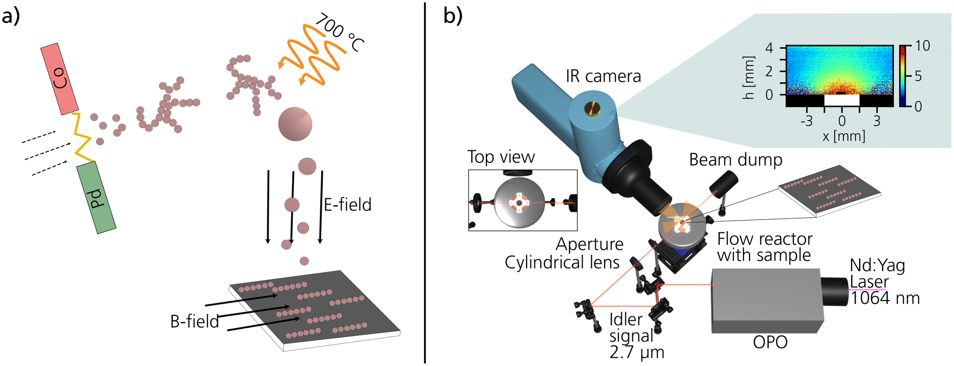 | ||
| Fig. 1 Schematics of the experimental setups used for the ENP generation and PLIF measurements. In (a) an illustration of the generation of ENPs by spark ablation, followed by sintering and compaction in-flight in a tube furnace, and finally deposited with a combined electric and magnetic field. In (b) the optical setup for the catalytic PLIF measurements, including all main components, is presented. | ||
2.2 Nanoparticle characterization
The ENPs were imaged and analyzed using scanning electron microscopy (SEM, Hitachi) and transmission electron microscopy (TEM, JEOL 3000). Energy-dispersive X-ray spectroscopy (XEDS) was used for composition quantification and qualitative elemental mapping in scanning transmission electron microscopy (STEM) mode. X-ray photoelectron spectroscopy (XPS) was performed at the solid-state end station41 of the FinEstBeAMS beamline at MAX IV Laboratory.422.3 Catalytic measurements
To study the catalytic activity of the ENPs, mass spectrometry (MS) in combination with planar laser-induced fluorescence (PLIF) measurements were performed at the Enoch Thulin Laboratory at the Division of Combustion Physics at Lund University. The ENPs deposited on silicon wafers were placed inside a 23 ml ambient-pressure flow reactor (Leiden probe microscopy (LPM)). The sample was positioned on a boron nitride resistive heater that was calibrated to a thermocouple.43 The gas flow was controlled by mass-flow-controller (Bronkhorst EL-FLOW) with the total flow set to 100 ml min−1. A pressure controller (Bronkhorst EL-PRESS) was used to keep the total pressure constant at 150 mbar. By flowing 80 ml min−1 CO (5% diluted in Ar), 4 ml min−1 O2, 16 ml min−1 Ar, and heating the sample from room temperature to 400 °C, the catalytic activity of the ENPs during CO oxidation was studied as a function of temperature. This was done by following the average CO2 production with MS at the reactor outlet and with PLIF right at the catalytic surface. The PLIF technique is based on imaging the fluorescent signal of CO2 with a liquid nitrogen-cooled IR camera (SBF-134, Santa Barbara Focalplane). The laser signal to excite the CO2 molecules is taken from the fundamental of a Nd:Yag laser at 1064 nm. This signal is passed through an optical parametric oscillator (OPO) where the excitation wavelength at 2.7 μm is reached. The fluorescence signal at 4.3 μm can be collected thanks to a filter placed in front of the IR camera. A more detailed description of the setup, the principle behind PLIF and information about the data analysis including temperature calibration can be found in previous works.44–463. Results and discussion
3.1 Nanoparticle characterization
The Co–Pd ENPs were generated, size-selected to 40 nm, and deposited in a combined electric and magnetic field, as described in section 2.1. For catalysis, 40 nm ENPs are considered large and smaller particles would be more appropriate for achieving a higher surface-to-volume ratio. However, the ENPs require a sufficient volume to facilitate robust nanochain formation, and 40 nm ENPs were selected for this purpose. Generation of ENPs by the aerosol method spark ablation enables a large span of material combinations to form multifunctional particles.47 Depending on the seed material and generation parameters, alloyed,48 core–shell,49 and multi-element high-entropy alloy mixtures50 can be synthesized. The size of the generated ENPs is controlled in the gas flow, and the deposition process of the aerosol particles enables bottom-up generation of magnetic nanochains from the very first particle.30The Co–Pd ENPs were assembled into well-defined nanochains, as illustrated in Fig. 2a. The nanochain formation was confirmed by TEM imaging (Fig. 2b). Single particle XEDS elemental mapping in STEM-mode further revealed that elemental Co and Pd were equally distributed throughout each nanoparticle in the nanochains (Fig. 2c–i). No detectable elemental phase-separation within the ENPs was observed and elemental Co and Pd were present in each individual particle as shown by the qualitative XEDS chemical mapping of Co (Fig. 2d and h) and Pd (Fig. 2e and i) from two randomly selected nanochains (Fig. 2c and g). The XEDS elemental quantification was performed on 50 individual nanoparticles and the relative amount of Co to Pd is plotted as a histogram in Fig. 2f. Both particles located in nanochains and separated from the chains were selected in the analysis, although the number of separated particles in the sample volume was few. The average metal composition of the Co–Pd particles was 57 at% Co and 43 at% Pd with a standard deviation of 3 at%. Within this composition range Co–Pd alloys are miscible and are expected to form a ferromagnetic fcc-structure.51 While there are possible metastable phases in this range, their presence in the Co–Pd ENPs has not been determined in this study. The quantification was performed by only studying the metallic elements and ignoring any organic contributions, i.e., oxygen and carbon since these elements contribute from the surrounding matrix and cannot be accurately quantified.
 | ||
| Fig. 2 Co–Pd ENP characterizations. (a) An illustration of the generated Co–Pd nanochains with both elements equally distributed in each nanoparticle. (b) TEM images show the nanochain formation in detail. In (c–e) and (g–i) XEDS element mapping of two different nanochains is shown, clearly visualizing that both Co and Pd are equally distributed in each nanoparticle. In (f) a histogram shows the distribution in composition of 50 different ENPs. | ||
When bimetallic ENPs are generated by spark ablation using electrodes of two different materials, the composition of the resulting nanoparticles depends on the electrode material as well as the generation parameters, such as the polarity of the electrodes.52,53 Obtaining well-mixed and non-phase-separated particles also requires a well-defined sintering temperature and materials that are not prone to segregate into core–shell structures.49 From molecular dynamics simulations, Co–Pd are expected to have a small tendency to form a core–shell structure with a slightly higher probability of the Pd atoms to occupy the surface.54 However, the generation of nanoparticles by spark ablation involves many complex steps, including nucleation, condensation, coalescence, sintering, and restructuring. These steps may influence the final structure of the particles, and molecular dynamics simulations may not accurately capture the combination of all these processes. Nevertheless, the chemical atom arrangement of the resulting Co–Pd nanoparticles appears to be well-mixed and not phase-separated.
3.2 Nanochain formation
Magnetic field-directed self-assembly30 was used to align and directly integrate Co–Pd ENPs onto pieces of Si wafer. Collecting charged aerosol ENPs by electrophoresis using an ESP is a common method to achieve a well-defined homogeneous distribution of deposited nanoparticles.39,40 It can also be used to form 2D patterns55 or assemble particles onto electrical devices.31When the electrostatic deposition is combined with an external magnetic field, magnetic ENPs can be guided to form highly ordered, vertically or horizontally, aligned nanochains extending in the same direction as the applied magnetic field.30 The external in-plane magnetic field, here 0.47 T, aligns the magnetization of the individual magnetic nanoparticles during deposition, which forces the particles to assemble in vertical chain-like structures. The direction of the magnetic field determines the direction in which the nanochains are assembled. The self-assembly is governed by the volume-dependent magnetic dipolar interaction.56,57 Particles with a high saturation magnetization have a strong particle–particle attraction. They are, therefore, more likely to be deposited into a nanochain rather than directly onto the support.30
The tendency of the Co–Pd ENPs to form nanochains is directly related to the magnetization of the nanoparticles. To evaluate this, size-selected 40 nm ENPs composed of Co, Pd, and Co–Pd were assembled, and the deposition patterns were compared. The SEM images in Fig. 3a–c display collections of 100 ENPs per μm2 and reveal obvious differences between the material systems. Both Co and Co–Pd assembled into extended nanochains, whereas the deposited Pd only shows random cluster formation, which is expected from weakly interacting non-magnetic nanoparticles.58
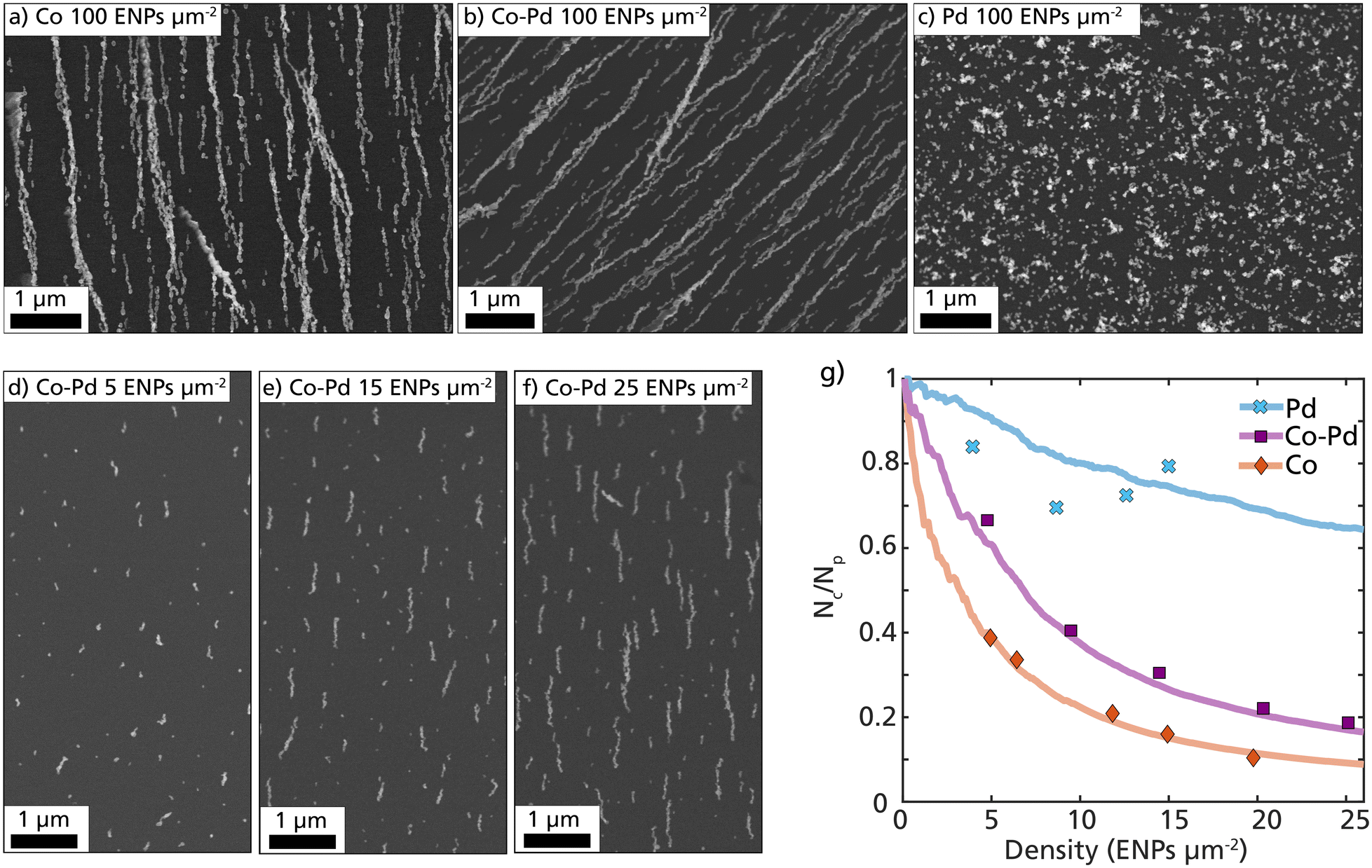 | ||
| Fig. 3 Magnetic field-directed self-assembly of Co, Co–Pd, and Pd ENPs. In (a–c) SEM images of size-selected 40 nm Co, Co–Pd, and Pd with a particle density of 100 ENPs per μm2 are displayed. In (d–f) the nanochain growth are displayed from a low particle concentration (5 ENPs per μm2) to a higher particle concentration (25 ENPs per μm2). In (g) quantitative differences in the particle–particle attraction for Pd (blue, crosses), Co–Pd (purple, squares), and Co (red, diamonds) are plotted. The data points are determined from SEM depositions, and the lines are based on simulated depositions of the different ENPs. | ||
The Co–Pd nanochain formation is visualized in Fig. 3d–f with SEM images at an increasing particle density on the substrate, starting from 5 ENPs per μm2 and ending at 25 ENPs per μm2. The particle concentration after size-selection was 5 × 10⁵ particles per cm3, which resulted in a deposition rate of approximately 1 ENPs per μm2 per minute of deposition. By removing the size-selection step, this rate would increase significantly. The probability of forming nanochains can be estimated and quantified by dividing the measured number of ENP clusters per unit area (Nc) by the calculated number of deposited ENPs per unit area (Np), as plotted in Fig. 3g. This fraction (Nc/Np) is expected to rapidly decay for particles with a strong interparticle attraction, as most deposited particles will have a higher probability of ending up in an already formed ENP cluster.
Samples with different ENP densities (ENPs per μm2) for Co, Pd, and Co–Pd were prepared and the number of clusters per unit area was identified and calculated using SEM (Fig. 3g, data points). More than 1000 particles from more than 10 different regions of interest were measured for each data point. These experimental data points were compared with computationally simulated depositions (Fig. 3g, lines). The simulations were performed by step-wise releasing individual nanoparticles in a defined volume and calculating their trajectories based on force contributions from applied fields and particle–particle interactions. More details about the simulations can be found in previous works.30,59
The experimental data points for pure Co ENPs followed the simulated Co lines very well with a rapid decay in the fraction Nc/Np, indicating that most particles end up in an already formed nanochain. The experimental data points for Co–Pd followed the same trend as Co, however the decay was slower. This indicates that the particle–particle attraction is not as strong as that of pure Co. This is expected considering that almost half of the atoms in the Co–Pd ENP are Pd and non-magnetic and will not contribute to the volume-dependent magnetic dipolar interaction. To mimic the Co–Pd ENPs in the simulations each particle was assigned a saturation magnetization based on the average at% of Co in the ENPs. In this assumption, the magnetization of each particle is only dependent on the number of Co atoms in the particles, and does not consider any interatomic effects from the Pd atoms. Based on the results from the simulations and the data points for Co–Pd, this assumption seems to be in good agreement, as can be seen in Fig. 3g.
Without performing any magnetization measurements, we can by observing the deposition pattern confirm that the Co–Pd ENPs exhibit a strong magnetization. The evident strong magnetic particle–particle interaction between the Co–Pd particles enabled considerable self-assembly and nanochain formation and there are no other material properties that can explain this evident chain formation. The main difference between the Co and Co–Pd nanochain pattern is that fewer Co ENPs are anchored to the substrate compared to Co–Pd due to the stronger interparticle attraction. Consequently, the nanochains are initially separated by a larger distance. Despite having an estimated saturation magnetization of almost half of the Co ENPs, the Co–Pd ENPs possessed enough magnetization to be guided into magnetic field-directed nanochains. These results demonstrate that nanochain formation is possible even for bimetallic nanoparticles if the total mass of magnetic elements in the ENP is sufficiently high enough. This is strong evidence of the multifunctional nature of these ENPs and indicates that the other non-magnetic mixing element can be replaced based on the desired functionality and still retain a magnetization large enough for nanochain formation.
3.3 Catalytic measurements
To study the catalytic behavior of the Co–Pd ENPs and compare it to monometallic Pd and Co ENPs, CO oxidation was chosen because of its well-studied nature and simple reaction mechanism which makes it suitable as a benchmark reaction. The catalytic reaction was performed at a total pressure of 150 mbar, with 6 mbar partial pressure each of CO and O2, diluted in 138 mbar Argon. The total flow was kept at 100 ml min−1. To initiate the reaction, the ENPs were heated at a rate of ∼1 °C s−1 from room temperature to 390 °C.MS and PLIF are used to monitor catalytic activity in operando. The laser-based technique, used to probe the gas phase, has previously been demonstrated to be a powerful method when studying catalytic samples operando at ambient pressures.60,61 While MS is sufficient to simply observe if the particles are catalytically active by monitoring the global gas composition in the chamber, PLIF aids in obtaining a spatially resolved image of the gas phase. This reveals whether the entire sample becomes active or only parts of it. Moreover, the laser probes the gas in proximity to the catalytic surface, leading to an instant response time and a better understanding of the gas right in the reaction zone.
Co–Pd and Co particles were chosen at a density of 300 ENPs per μm2 while the sample with pure Pd particles was chosen at a density of 150 ENPs per μm2. This aids us in comparing Pd and Co–Pd ENPs with a similar amount of Pd content. Since Co is expected to be less active than Pd particles, a high number density (300 ENPs per μm2) of Co particles was chosen as a reference sample.
The catalytic activity was monitored by following the MS CO2 signal and by imaging the fluorescent signal of CO2 at 4.3 μm with the IR camera continuously while the sample temperature was being ramped. The first observation is that both Pd and Co–Pd ENPs are catalytically active which is indicated by an increasing CO2 production from 300 °C onwards indicated by both the MS and PLIF trends in Fig. 4m. However, under the present conditions, no comparable catalytic activity could be measured for the Co ENP, as shown by the flat red MS trend in Fig. 4m. Both Co–Pd and Pd particles pass through the commonly observed regimes during CO oxidation: (i) a CO poisoned stage, (ii) a kinetic-limited, and finally, (iii) a mass-transfer-limited regime. The transition from regime (ii) to (iii) is marked by a sudden increase in activity, whereafter it remains nearly invariant with increasing temperature throughout regime (iii). This ignition happens at a specific temperature, which was observed to be almost the same for both the Pd and the Co–Pd samples. The similar ignition temperature of the two samples suggests that Pd is present on the surface also of the CoPd nanoparticles, where CO molecules strongly adsorb at low temperatures. As the temperature increases, CO can desorb, allowing oxygen to dissociate and initiate the CO oxidation reaction, as observed in the MS and PLIF traces.
 | ||
| Fig. 4 PLIF and MS measurements of Co–Pd, Co and Pd. In (a–d), (e–h), and (i–l) PLIF images are shown for the three different ENP systems Pd (150 ENPs per μm2), Co–Pd (300 ENPs per μm2) and Co (300 ENPs per μm2) respectively at four different temperatures (290 °C, 320 °C, 350 °C, and 380 °C). The color bars correspond to the calibrated partial pressure of CO2. The grey box shown in (a) shows the region of interest that is used to create the trends shown in (m). The white box indicates where the sample is positioned with a size of 3 × 3 mm. In (m) the MS trends for Co–Pd, Pd, and Co are shown in green, yellow, and red lines, respectively. In addition, the PLIF trends are shown for Pd and Co–Pd with dotted markers. Here, an average of 10 PLIF images were used. | ||
The PLIF images help us understand the gas phase distribution across the nanoparticles. The samples are homogeneously active across their entire surface with the highest CO2 concentration being right at the surface-gas interface as shown in Fig. 4d and h. This confirms a homogeneous deposition of the nanoparticles from the aerosol phase onto the substrate. The CO2 region increases from the middle of the sample outwards due to the heating and gas diffusion from the center outwards.62 In the present PLIF trend (Fig. 4m, dotted lines), fluctuations originate from the variances in the profile image that is used as a background calibration, which also leaves the images in Fig. 4a–d appearing with a stronger gradient from the region with high CO2 to low CO2 concentration. This could originate from a difference in laser power at the point of measurement. Given these fluctuations, no clear difference in PLIF signal between the two samples can be identified.
Several interesting conclusions can be drawn from these catalytic measurements. First, it is clearly visible that the Co–Pd sample is active and stable with no loss of activity throughout regime (iii). Moreover, the activity of the Pd 150 ENPs per μm2 seems to match the ignition temperature and the activity in regime (ii) of the Co–Pd 300 ENPs per μm2 sample quite well. This suggests that the Pd ENPs are the active material that mainly contributes to the reaction. On the one hand, we conclude that adding Co to the nanoparticles does not significantly affect the stability or performance of the catalyst. On the other hand, it does not enhance the performance either. In regime (iii), a discrepancy in the MS signal can be observed which could be attributed to a different gas diffusion geometry because of a different sample structure, i.e., particle density. Moreover, it is noticeable that the Co ENPs seem to be almost inactive. While one could identify a small signal in the PLIF images, we cannot exclude that this signal originates from thermal variations or fluctuations in the background signal.
3.4 Nanochain stability
It is important that a catalyst does not undergo significant structural changes during the chemical reaction to ensure reproducible performance and stability. During the catalytic measurements, each sample was heated to close to 400 °C and cooled to room temperature several times. The morphology of the Co–Pd nanochains and Pd nanoparticles were therefore investigated using SEM and XPS before and after the catalytic measurements.The self-assembled Co–Pd nanoparticles retained their nanochain morphology and remained highly aligned even after many heating ramps (Fig. 5a and c). Minor sintering can be observed in the neck region between the nanoparticles, leading to slight changes in the morphology and size of each nanoparticle (Fig. 5c). Furthermore, some structural changes had occurred on the surface of the nanoparticle, transforming from a smooth to a rougher surface. The transformation does not seem to be detrimental, as the same sample was measured during multiple ramping and on different occasions with the same result in activity. On the other hand, the Pd nanoparticles assembled as weakly interacting nanoparticles and formed small compact clusters on the substrate (Fig. 5b). Many of these clusters appeared to be sintered after heating (Fig. 5d). The observed minor sintering of the Co–Pd and Pd nanoparticles is difficult to avoid yet is undesirable as it reduces the surface area, and thus the available catalytically active surface atoms. It should be noted that the SEM images are not from identical locations but are instead representative images of the nanostructures on the substrate.
 | ||
| Fig. 5 Nanochain stability and surface composition. In (a and b) ENP depositions of Co–Pd and Pd before PLIF measurements, and in (c and d) the same sample after PLIF measurements. Minor sintering of the agglomerates was observed after PLIF measurements. In (e and f) XPS measurements of Pd 3d and Co 2p of the Co-Pd ENP before and after catalytic PLIF measurements. | ||
Denser aggregates with fewer nanoparticles are expected to sinter more rapidly than elongated nanochains,63 however, for these heating conditions it did not seem to influence the catalytic activity as both Co–Pd and Pd samples were measured with several temperature ramps without changing their catalytic activity dramatically. According to molecular dynamics simulations, the time for a nanochain to sinter increases with the number of nanoparticles in a nanochain, and longer chains are expected to withstand higher temperatures.64 Here, during the present reaction parameters (rapid temperature ramping to 400 °C) it is difficult to verify any advantages with the assumed more stable nanochains, and further studies are required on the thermal stability of such nanochains at elevated temperatures.
The chemical surface compositions of the Co–Pd particles were studied before and after catalytic measurements using XPS (Fig. 5e and f). The XPS spectra were background subtracted with Shirley backgrounds, and the binding energy was calibrated using the Fermi edge. The peak shapes of the Pd 3d spectrum were highly asymmetric before catalytic measurements, with peak position at 335.6 eV, indicating metallic Pd on the surface (Fig. 5e). However, the binding energy of the Co–Pd is higher than reported for metallic Pd in the literature,65 which indicates interatomic interaction between the Co and the Pd atoms. After exposing the Co–Pd ENPs to temperature ramping in CO, the Pd peaks shifted approximately 1.2 eV to higher binding energy with a wider peak shape, indicating a PdO-like structure on the surface. It is also noticeable that the signal for PdO under these conditions became much noisier, which can be explained by the expected CO poisoning at the Pd-sites on the surface.
Turning to the Co contribution of the surface of the Co–Pd ENPs (Fig. 5f). Before the catalytic measurements, the Co 2p spectral lines revealed a large contribution from satellite structures next to the main peaks. The large satellite structures are significant for the presence of CoO.66,67 After the catalytic measurements, the satellite structures became weaker but were still present. Based on the shape, we believe that the chemical surface structure changed from a CoO dominant to a mixture of CoO and Co2O3,67 however from the measurements, it was not possible to resolve the exact contribution of each oxide.
Although no metallic Co peak (at 778.1 eV) was resolved in the XPS data, we estimate that only the surface layers of the ENPs are oxidized. Due to the relatively large size of the nanoparticles (40 nm), we expect that the core structure of the particles is different from the surface structure, and a passivating oxide layer forms that protects the inner core both in the aerosol phase as well as after being deposited and exposed to an ambient environment. Previous bulk characterization of single element Co ENPs and alloyed Co–Ni prepared with the same method as in this study have been reported to form a core of metallic Co.35,68 Furthermore, the strong nanochain formation implies large magnetization and ferromagnetic nature of the ENPs, which is attained from metallic Co.
4. Conclusions
In this work, we have synthesized and self-assembled multifunctional Co–Pd ENPs into nanochains and evaluated their magnetic and catalytic properties. We conclude that the Co–Pd nanochains with 57 at% Co exhibits large magnetization and are useful as a catalyst for CO oxidation. The two elements are arranged homogeneously throughout each individual ENP, and the intermixing does not negatively affect the magnetic or catalytic properties compared to the monometallic counterpart. The magnetization of the Co–Pd ENPs is estimated to be close to theoretical values if the number of Co atoms in the ENPs is considered. Furthermore, from the catalytic measurements, we can conclude that the Co–Pd particles are comparable with pure Pd nanoparticles, considering the same amount of Pd being used. This indicates that by intermixing Co and Pd, the magnetic and catalytic functionalities of the individual elements are retained while creating unique ENPs with dual functionalities. Further studies on the crystal structure and magnetization are required to evaluate the synthesized multifunctional nanoparticle system in detail.The main advantage of the intermixed particle compared to the pure monometallic nanoparticles is the possibility to create unique nanostructures. By adding magnetic elements to catalytic nanoparticles, the assembled nanostructures can obtain the benefits of nanochain formation, including the larger surface area, stability, and the possibility of arranging the particles in a complex matrix and onto devices. Similarly, it also implies that it may be possible to generate nanochains with desired reactivity depending on the mixing catalytic element. We highlight the simplicity and potential of forming multifunctional nanochains with a possibly wide array of desired functionalities, depending on the elements mixed. Complementary studies using other material combinations would be needed to conclude if this can be a general approach for multifunctional nanochain synthesis.
Data availability
Data for this article, including SEM images and XEDS results supporting histogram in Fig. 2 and data points in Fig. 3 are available at Zenodo at https://doi.org/10.5281/zenodo.12541594 Data will be available from 1st of January 2025.Conflicts of interest
There are no conflicts to declare.Acknowledgements
The following funding is acknowledged: Knut and Alice Wallenberg foundation (KAW)-funded project “Atomistic design of new catalysts” (project no. KAW 2015.0058), the Swedish Foundation for Strategic Research (project no. ITM17-0045), the Swedish Research Council (project no. 2023-04708, and 2019-04970). Part of the experimental work was performed in Lund Nano Lab, part of Myfab research infrastructure.We acknowledge MAX IV Laboratory for time on Beamline FinEstBeAMS and beamline scientist Weimin Wang for support during XPS measurements. Research conducted at MAX IV, a Swedish national user facility, is supported by the Swedish Research council under contract 2018-07152, the Swedish Governmental Agency for Innovation Systems under contract 2018-04969, and Formas under contract 2019-02496.
References
- M. R. Buck, J. F. Bondi and R. E. Schaak, Nat. Chem., 2012, 4, 37–44 CAS.
- H. Yu, M. Chen, P. M. Rice, S. X. Wang, R. L. White and S. Sun, Nano Lett., 2005, 5, 379–382 CAS.
- N. E. Motl, A. K. P. Mann and S. E. Skrabalak, J. Mater. Chem. A, 2013, 1, 5193–5202 CAS.
- J. Shi, Chem. Rev., 2013, 113, 2139–2181 CAS.
- N. Sanvicens and M. P. Marco, Trends Biotechnol., 2008, 26, 425–433 CrossRef CAS.
- M. Angelakeris, Biochim. Biophys. Acta, Gen. Subj., 2017, 1861, 1642–1651 CrossRef CAS.
- S. Duan and R. Wang, Prog. Nat. Sci.:Mater. Int., 2013, 23, 113–126 CrossRef.
- K. D. Gilroy, A. Ruditskiy, H. C. Peng, D. Qin and Y. Xia, Chem. Rev., 2016, 116, 10414–10472 CrossRef CAS.
- D. Liu, Y. Huang, J. Hu, B. Wang and Y. Lu, ChemCatChem, 2022, 14, e202200889 CrossRef CAS.
- Y. Jiang, Y. Guo, Y. Zhou, S. Deng, L. Hou, Y. Niu and T. Jiao, ACS Omega, 2020, 5, 14805–14813 CrossRef CAS PubMed.
- S. Wang, J. Fu, K. Wang, M. Gao, X. Wang, Z. Wang, J. Chen and Q. Xu, Appl. Surf. Sci., 2018, 459, 208–216 CrossRef CAS.
- S. Ekeroth, E. P. Münger, R. Boyd, J. Ekspong, T. Wågberg, L. Edman, N. Brenning and U. Helmersson, Nano Lett., 2018, 18, 3132–3137 CrossRef CAS.
- E. K. Athanassiou, P. Grossmann, R. N. Grass and W. J. Stark, Nanotechnology, 2007, 18, 165606 CrossRef.
- H. Niu, Q. Chen, H. Zhu, Y. Lin and X. Zhang, J. Mater. Chem., 2003, 13, 1803–1805 RSC.
- C. Jiang, C. W. Leung and P. W. T. Pong, Nanoscale Res. Lett., 2016, 11, 189 CrossRef PubMed.
- G. H. Lee, S. H. Huh, J. W. Park, H. C. Ri and J. W. Jeong, J. Phys. Chem. B, 2002, 106, 2123–2126 CrossRef CAS.
- G. K. Das, C. S. Bonifacio, J. De Rojas, K. Liu, K. van Benthem and I. M. Kennedy, J. Mater. Chem. A, 2014, 2, 12974–12981 RSC.
- S. Ekeroth, J. Ekspong, D. K. Perivoliotis, S. Sharma, R. Boyd, N. Brenning, E. Gracia-Espino, L. Edman, U. Helmersson and T. Wågberg, ACS Appl. Nano Mater., 2021, 4, 12957–12965 CrossRef CAS.
- D. Toulemon, M. V. Rastei, D. Schmool, J. S. Garitaonandia, L. Lezama, X. Cattoën, S. Bégin-Colin and B. P. Pichon, Adv. Funct. Mater., 2016, 26, 2454–2462 CrossRef CAS.
- G. Cheng, D. Romero, G. T. Fraser and A. R. H. Walker, Langmuir, 2005, 21, 12055–12059 CrossRef CAS PubMed.
- W. Zhang, P. K. J. Wong, D. Zhang, J. Yue, Z. Kou, G. van der Laan, A. Scholl, J. G. Zheng, Z. Lu and Y. Zhai, Adv. Funct. Mater., 2017, 27, 1–9 Search PubMed.
- Z. Kou, E. Liu, J. Yue, Y. Sui, Z. Huang, D. Zhang, Y. Wang, Y. Zhai, J. Du and H. Zhai, J. Appl. Phys., 2015, 117, 17E709 CrossRef.
- A. C. Genix and J. Oberdisse, Soft Matter, 2018, 14, 5161–5179 RSC.
- M. R. Jones, K. D. Osberg, R. J. MacFarlane, M. R. Langille and C. A. Mirkin, Chem. Rev., 2011, 111, 3736–3827 CrossRef CAS.
- B. Su, C. Zhang, S. Chen, X. Zhang, L. Chen, Y. Wu, Y. Nie, X. Kan, Y. Song and L. Jiang, Adv. Mater., 2014, 26, 2501–2507 CrossRef CAS PubMed.
- G. Biskos, V. Vons, C. U. Yurteri and A. Schmidt-Ott, KONA Powder Part. J., 2008, 26, 13–35 CrossRef.
- P. Grammatikopoulos, S. Steinhauer, J. Vernieres, V. Singh and M. Sowwan, Adv. Phys.:X, 2016, 1, 81–100 CAS.
- R. Strobel and S. E. Pratsinis, J. Mater. Chem., 2007, 17, 4743–4756 RSC.
- M. E. Messing, J. Green Eng., 2016, 5, 83–96 CrossRef.
- C. Preger, M. Josefsson, R. Westerström and M. E. Messing, Nanotechnology, 2021, 32, 195603 CrossRef CAS PubMed.
- M. Sedrpooshan, C. Bulbucan, P. Ternero, P. Maltoni, C. Preger, S. Finizio, B. Watts, D. Peddis, A. M. Burke, M. E. Messing and R. Westerström, Nanoscale, 2023, 15, 18500–18510 RSC.
- S. Schwyn, E. Garwin and A. Schmidt-Ott, J. Aerosol Sci., 1988, 19, 639–642 CrossRef CAS.
- T. V. Pfeiffer, J. Feng and A. Schmidt-Ott, Adv. Powder Technol., 2014, 25, 56–70 CrossRef CAS.
- B. O. Meuller, M. E. Messing, D. L. J. Engberg, A. M. Jansson, L. I. M. Johansson, S. M. Norlén, N. Tureson and K. Deppert, Aerosol Sci. Technol., 2012, 46, 1256–1270 CrossRef CAS.
- R. T. Hallberg, L. Ludvigsson, C. Preger, B. O. Meuller, K. A. Dick and M. E. Messing, Aerosol Sci. Technol., 2018, 52, 347–358 CrossRef CAS.
- J. Feng, L. Huang, L. Ludvigsson, M. E. Messing, A. Maisser, G. Biskos and A. Schmidt-Ott, J. Phys. Chem. C, 2016, 120, 621–630 CrossRef CAS.
- J. Feng, N. Ramlawi, G. Biskos and A. Schmidt-Ott, Aerosol Sci. Technol., 2018, 52, 505–514 CrossRef CAS.
- M. N. A. Karlsson, K. Deppert, L. S. Karlsson, M. H. Magnusson, J. O. Malm and N. S. Srinivasan, J. Nanopart. Res., 2005, 7, 43–49 CrossRef CAS.
- J. Dixkens and H. Fissan, Aerosol Sci. Technol., 1999, 30, 438–453 CrossRef CAS.
- C. Preger, N. C. Overgaard, M. E. Messing and M. H. Magnusson, Aerosol Sci. Technol., 2020, 54, 718–728 CrossRef CAS.
- W. Wang, A. Kivimäki, K. Chernenko, R. Pärna, T. Käämbre, E. Kukk, K. Kokko, M. Valden, M. Hirsimäki, M. Kirm and M. Huttula, J. Phys.: Conf. Ser., 2022, 2380, 012048 CrossRef.
- R. Pärna, R. Sankari, E. Kukk, E. Nõmmiste, M. Valden, M. Lastusaari, K. Kooser, K. Kokko, M. Hirsimäki, S. Urpelainen, P. Turunen, A. Kivimäki, V. Pankratov, L. Reisberg, F. Hennies, H. Tarawneh, R. Nyholm and M. Huttula, Nucl. Instrum. Methods Phys. Res., Sect. A, 2017, 859, 83–89 CrossRef.
- S. Pfaff, H. Karlsson, F. A. Nada, E. Lundgren and J. Zetterberg, J. Phys. D: Appl. Phys., 2019, 52, 324003 CrossRef CAS.
- S. Pfaff , Lunds tekniska högskola. Fysiska institutionen and Media-Tryck, Lund Reports Combust. Physics.
- J. Zhou, S. Pfaff, E. Lundgren and J. Zetterberg, Appl. Phys. B:Lasers Opt., 2017, 123, 1–8 CrossRef CAS.
- L. Rämisch, S. Pfaff, S. M. Gericke, E. Lundgren and J. Zetterberg, Catal. Today, 2024, 427, 114441 CrossRef.
- J. H. Byeon and J. H. Park, Sci. Rep., 2016, 6, 1–7 CrossRef.
- C. Preger, C. Bulbucan, B. O. Meuller, L. Ludvigsson, A. Kostanyan, M. Muntwiler, K. Deppert, R. Westerström and M. E. Messing, J. Phys. Chem. C, 2019, 123, 16083–16090 CrossRef CAS.
- M. Snellman, N. Eom, M. Ek, M. E. Messing and K. Deppert, Nanoscale Adv., 2021, 3, 3041–3052 RSC.
- J. Feng, D. Chen, P. V. Pikhitsa, Y. ho Jung, J. Yang and M. Choi, Matter, 2020, 3, 1646–1663 CrossRef.
- K. Ishida and T. Nishizawa, J. Phase Equilib., 1991, 12, 83–87 CrossRef CAS.
- M. Domaschke, M. Schmidt and W. Peukert, J. Aerosol Sci., 2018, 126, 133–142 CrossRef CAS.
- A. Kohut, L. P. Villy, A. Kéri, Á. Bélteki, D. Megyeri, B. Hopp, G. Galbács and Z. Geretovszky, Sci. Rep., 2021, 11, 1–10 CrossRef PubMed.
- N. Eom, M. E. Messing, J. Johansson and K. Deppert, ACS Nano, 2021, 15, 8883–8895 CrossRef CAS.
- T. J. Krinke, H. Fissan, K. Deppert, M. H. Magnusson and L. Samuelson, Appl. Phys. Lett., 2001, 78, 3708–3710 CrossRef CAS.
- L. Balcells, I. Stanković, Z. Konstantinović, A. Alagh, V. Fuentes, L. López-Mir, J. Oró, N. Mestres, C. García, A. Pomar and B. Martínez, Nanoscale, 2019, 11, 14194–14202 RSC.
- K. Butter, P. H. H. Bomans, P. M. Frederik, G. J. Vroege and A. P. Philipse, Nat. Mater., 2003, 2, 88–91 CrossRef CAS PubMed.
- T. J. Krinke, H. Fissan and K. Deppert, Phase Transitions, 2003, 76, 333–345 CrossRef CAS.
- M. Josefsson, M-Josefsson/AeroDep v1.0.0, 2020, DOI:10.5281/ZENODO.3937281.
- S. Blomberg, J. Zhou, J. Gustafson, J. Zetterberg and E. Lundgren, J. Phys.: Condens. Matter, 2016, 28, 453002 CrossRef PubMed.
- K. Reuter, Operando Research in Heterogeneous Catalysis, Springer International Publishing, Cham, 2017, vol. 114 Search PubMed.
- S. Pfaff, L. Rämisch, S. M. Gericke, A. Larsson, E. Lundgren and J. Zetterberg, ACS Catal., 2022, 12, 6589–6595 CrossRef CAS.
- M. L. Eggersdorfer, D. Kadau, H. J. Herrmann and S. E. Pratsinis, Langmuir, 2011, 27, 6358–6367 CrossRef CAS PubMed.
- T. Hawa and M. R. Zachariah, Phys. Rev. B:Condens. Matter Mater. Phys., 2007, 76, 1–9 CrossRef.
- S. Blomberg, J. Gustafson, N. M. Martin, M. E. Messing, K. Deppert, Z. Liu, R. Chang, V. R. Fernandes, A. Borg, H. Grönbeck and E. Lundgren, Surf. Sci., 2013, 616, 186–191 CrossRef CAS.
- T. J. Chuang, C. R. Brundle and D. W. Rice, Surf. Sci., 1976, 59, 413–429 CrossRef CAS.
- M. C. Biesinger, B. P. Payne, A. P. Grosvenor, L. W. M. Lau, A. R. Gerson and R. S. C. Smart, Appl. Surf. Sci., 2011, 257, 2717–2730 CrossRef CAS.
- P. Ternero, M. Sedrpooshan, D. Wahlqvist, B. O. Meuller, M. Ek, J. M. Hübner, R. Westerström and M. E. Messing, J. Aerosol Sci., 2023, 170, 1–11 CrossRef.
| This journal is © The Royal Society of Chemistry 2025 |