
 Open Access Article
 This Open Access Article is licensed under a Creative Commons Attribution-Non Commercial 3.0 Unported Licence
Illuminating the multi-stage sodium storage mechanisms in high-rate porous hard carbon: mechanistic insights from a pore architecture†
Yulin
Mao‡
,
Yueyang
Wang‡
 ,
Yuyang
Zhao
,
Qingyuan
Li
,
Guoxing
Sun
* and
Guichuan
Xing
*
,
Yuyang
Zhao
,
Qingyuan
Li
,
Guoxing
Sun
* and
Guichuan
Xing
*
Institute of Applied Physics and Materials Engineering, University of Macau, Avenida da Universidade, Taipa, Macau SAR, China. E-mail: gxsun@um.edu.mo; gcxing@um.edu.mo
First published on 4th March 2025
Abstract
Elucidating the multi-stage sodium storage mechanisms in porous hard carbon is pivotal for advancing sodium-ion battery (SIB) technology. In this work, we systematically investigate the three-stage sodium storage mechanisms in porous hard carbon featuring a tailored pore architecture, which achieves exceptional rate performance (204.8 and 158.83 mA h g−1 at 1 and 2 A g−1) while maintaining a capacity retention of 75% over 1000 cycles at 1 A g−1. By combining electrochemical analyses with multi-scale characterization, we reveal how hierarchical porosity coordinates the three-stage sodium storage mechanisms: macropores facilitate rapid ion transport, mesopores enhance adsorption kinetics, and micropores enable stable pore-filling. In situ EIS and GITT analyses quantitatively correlate the interconnected pore network with improved Na+ diffusion kinetics and reduced interfacial resistance. These findings establish design principles for hard carbons that simultaneously optimize multi-mechanistic storage and high-power operation in practical SIBs.
Introduction
Hard carbon (HC) has garnered significant attention as a promising anode material for sodium-ion batteries (SIBs),1–5 owing to its disordered architecture that enables sodium storage via multiple mechanisms. Unlike graphite, whose intercalation compounds are thermodynamically unstable for sodium, hard carbon accommodates sodium through a complex interplay of adsorption at defect sites, intercalation between pseudo-graphitic layers, and pore-filling at lower potentials.6–11 These three primary mechanisms operate across distinct voltage ranges, contributing to the overall capacity.12,13 However, the intricate coupling of these mechanisms, particularly in porous hard carbons with diverse pore networks, remains inadequately understood.14–16 A deeper insight into this multi-stage sodium storage process is essential for advancing high-performance SIBs.17,18Recent advances in template-assisted synthesis, e.g. MgO19 and ZnO templating,10,20–22 have been extensively explored to create porous hard carbons with tunable structures, enabling improved sodium storage capabilities. While these developments have improved capacity metrics, the rate performance of most reported HC materials remains suboptimal, typically showing <150 mA h g−1 at 2 A g−1.23–26 This limitation stems from insufficient understanding of how pore networks govern ionic transport kinetics while simultaneously supporting multi-stage storage mechanisms.27,28
This work addresses this knowledge gap by investigating HC-2, a model material exhibiting exceptional rate capability (204.8 mA h g−1 at 1 A g−1 and 158.83 mA h g−1 at 2 A g−1) coupled with stable cycling performance. Also, through a multi-technique approach combining a galvanostatic intermittent titration technique (GITT), in situ electrochemical impedance spectroscopy (EIS), and depth-profiling X-ray photoelectron spectroscopy (XPS), we establish how the pore structure of HC-2 facilitates rapid sodium transport while maintaining effective storage across all three mechanisms. The macropore network (50–200 nm) serves as ionic highways, reducing concentration polarization at high currents, while mesopores (2–50 nm) and micropores (<2 nm) synergistically contribute to adsorption and pore-filling processes. This structural design enables HC-2 to achieve a high apparent Na+ diffusion coefficient, explaining its superior rate performance. Furthermore, our electrolyte engineering using diglyme-based solutions demonstrates how pore–electrolyte interactions influence SEI formation, revealing that the HC-2's pore architecture promotes uniform SEI layers that remain stable during high-rate cycling.29–31 These findings advance the fundamental understanding of structure–kinetics relationships in porous carbons, while providing concrete design principles for high-power SIB anodes.32
On this basis, we seek to provide a comprehensive elucidation of the three-stage sodium storage mechanisms through a series of advanced ex situ and in situ electrochemical characterization techniques, including GITT, cyclic voltammetry (CV), EIS, and corresponding structural/morphological analyses. By systematically correlating the pore architecture with the observed storage modes, we demonstrate how each stage—adsorption, intercalation, and pore-filling—contributes to the total capacity, and how they evolve with cycling. This multi-pronged approach enables us to verify mechanistic insights through complementary experiments, thus offering a holistic picture of sodium uptake pathways in porous HC.
Results and discussion
Fig. 1 illustrates the preparation process of HC-1, HC-2, and HC-3. Zinc gluconate and glucose were selected as precursors and mixed at a molar ratio of 1![[thin space (1/6-em)]](https://www.rsc.org/images/entities/char_2009.gif) :119 and then dissolved in deionized water to prepare the precursor solution. For HC-1, the precursor solution was gradually frozen in a refrigerator to reduce the cooling rate, followed by freeze-drying and pyrolysis at 1300 °C under an argon atmosphere.33 For HC-2, the precursor solution was added in small portions, multiple times, into an excess of liquid nitrogen to ensure rapid and uniform quenching of zinc gluconate crystals at the nanoscale. This flash-freezing step was designed to increase the content of nanoscale zinc gluconate crystals, which, upon pyrolysis, enhanced the formation of nanoscale ZnO.19 The presence and stable dispersion of ZnO nanoparticles were confirmed by heating the precursor under an argon atmosphere to 700 °C, followed by natural cooling, yielding HC-2-ZnO, a hard carbon encapsulating nanoscale ZnO. Fig. S1 (ESI†) presents transmission electron microscopy (TEM) images clearly showing ZnO nanoparticles (∼5 nm) uniformly distributed within the carbon matrix. Acting as an etching agent, nanoscale ZnO significantly increased the micropore content in HC-2, thereby enhancing its sodium storage performance.33 After flash freezing, the samples were freeze-dried and subjected to the same pyrolysis process. For HC-3, the zinc gluconate and glucose powders were directly mixed via mechanical grinding and pyrolyzed without undergoing any freezing or freeze-drying steps.
:119 and then dissolved in deionized water to prepare the precursor solution. For HC-1, the precursor solution was gradually frozen in a refrigerator to reduce the cooling rate, followed by freeze-drying and pyrolysis at 1300 °C under an argon atmosphere.33 For HC-2, the precursor solution was added in small portions, multiple times, into an excess of liquid nitrogen to ensure rapid and uniform quenching of zinc gluconate crystals at the nanoscale. This flash-freezing step was designed to increase the content of nanoscale zinc gluconate crystals, which, upon pyrolysis, enhanced the formation of nanoscale ZnO.19 The presence and stable dispersion of ZnO nanoparticles were confirmed by heating the precursor under an argon atmosphere to 700 °C, followed by natural cooling, yielding HC-2-ZnO, a hard carbon encapsulating nanoscale ZnO. Fig. S1 (ESI†) presents transmission electron microscopy (TEM) images clearly showing ZnO nanoparticles (∼5 nm) uniformly distributed within the carbon matrix. Acting as an etching agent, nanoscale ZnO significantly increased the micropore content in HC-2, thereby enhancing its sodium storage performance.33 After flash freezing, the samples were freeze-dried and subjected to the same pyrolysis process. For HC-3, the zinc gluconate and glucose powders were directly mixed via mechanical grinding and pyrolyzed without undergoing any freezing or freeze-drying steps.
 | ||
| Fig. 1 Schematic illustration of the synthesis process of HC-1, HC-2, and HC-3. | ||
This systematic synthesis strategy highlights the critical role of freezing methods in determining the pore structure of hard carbon. Gradual freezing in HC-1 led to the formation of medium-sized pores by slowing the crystallization of zinc gluconate, while the rapid quenching in HC-2 enhanced the structural uniformity and microporosity due to the increased nanoscale ZnO content. In contrast, the absence of a freezing step in HC-3 resulted in a less porous structure, as no precursor crystallization occurred before pyrolysis. This approach provides valuable insights into the relationship between synthesis conditions and sodium storage behavior in porous hard carbon materials.
The synthesis method plays a pivotal role in shaping the morphology, pore structure, and chemical properties of the hard carbon samples,34 as illustrated in Fig. 2a–c. SEM images reveal distinct differences among the samples. HC-1, prepared by gradual freezing, exhibits a relatively porous and uniform structure, with microstructural features visible on the fractured particle surfaces.35 In contrast, HC-2, synthesized via flash freezing, consists of more fragmented and irregular particles with highly intricate, three-dimensional surface microstructures. This suggests that rapid solidification disrupted structural uniformity and promoted pore formation, with macropore networks likely resulting from the high-temperature etching effects of zinc oxide nanoparticles. HC-3, which was synthesized without a freezing step, presents compact morphology with smoother surfaces, indicating limited pore development due to the direct pyrolysis of mechanically mixed precursors. These morphological differences, dictated by the freezing method, significantly influence the pore structure and surface properties, as confirmed by BET analysis.
 | ||
| Fig. 2 Characterization of HC-1, HC-2, and HC-3. (a)–(c) SEM images showing the distinct morphologies of HC-1, HC-2, and HC-3, influenced by the synthesis methods. (d)–(f) TEM images of HC-1, HC-2 and HC-3, respectively. (g) BET isotherms indicating differences in specific surface areas and pore structures. (h) XRD patterns confirming the low crystallinity of all samples, with broad peaks corresponding to pseudo-graphitic domains. (i) Raman spectra highlighting the structural disorder, with differences in ID/IG ratios across the samples. (j)–(l) XPS analysis revealing variations in elemental compositions and bonding states among the samples. | ||
TEM images (Fig. 2d–f) provide further insights into the microstructures of the hard carbon samples. HC-1 (Fig. 2d) exhibits pseudo-graphitic layers with moderate disorder, reflecting a balance between graphitic ordering and porosity. HC-2 (Fig. 2e) shows mixed morphology of pseudo-graphitic carbon layers with abundant nanoscale pores (highlighted in yellow), consistent with the SEM and BET results indicating high porosity. These nanopores facilitate a large surface area, enhancing sodium ion adsorption and storage capacity. HC-3 (Fig. 2f) displays pseudo-graphitic layers with minimal pore development, confirming its compact nature (Fig. S2, ESI†). The structural variations observed in TEM align with the synthesis-induced changes in morphology and porosity.
BET results and nitrogen adsorption/desorption isotherms (Fig. 2g) further highlight the critical influence of synthesis conditions on pore characteristics.36 HC-1 exhibits a combination of type-I and type-IV isotherms, indicative of a microporous structure with some mesoporosity.37 HC-2 predominantly shows characteristics of microporous materials, while HC-3 exhibits a type-II isotherm, typical of nonporous or macroporous structures. Surface area measurements confirm these differences: HC-2 achieves the highest surface area (532.69 m2 g−1) due to its well-developed pore network from rapid quenching, HC-1 has a moderate surface area (186.15 m2 g−1), and HC-3 has the lowest (98.73 m2 g−1) due to the absence of a freezing step. These variations in surface areas and pore structures, directly linked to the synthesis methods, are critical for sodium storage, as they determine the ion-accessible surface and availability of adsorption and intercalation sites.38
The XRD patterns (Fig. 2h) confirm the low crystallinity of all samples, with broad diffraction peaks at 2θ = 21–23° and 42–44° corresponding to the 002 and 100 planes of pseudo-graphitic domains.39 Notably, the absence of sharp crystalline peaks confirms the complete decomposition of the zinc gluconate precursor during pyrolysis.40 The consistency of the diffraction patterns across the samples suggests that, while synthesis methods strongly influence morphology and porosity, they have a limited effect on the graphitic domain structure.41
Raman spectra (Fig. 2i) provide further insights into the structural disorder of the samples.42 All exhibit a prominent D-band (∼1350 cm−1) and G-band (∼1580 cm−1), corresponding to disordered and graphitic carbon, respectively. The ID/IG ratio, an indicator of disorder, follows the trend HC-2 > HC-3 > HC-1. The highest disorder in HC-2 aligns with its high surface area and extensive microporosity, which can enhance sodium storage capacity by providing abundant active sites for ion adsorption.43 These findings highlight the direct impact of synthesis methods on the structural characteristics of hard carbon, which in turn govern its electrochemical performance.
XPS analysis (Fig. 2j–l) further elucidates the role of surface chemistry in sodium storage.44 Survey spectra confirm the presence of carbon and oxygen as the dominant elements, with variations in the oxygen content reflecting differences in functional groups introduced by the synthesis process.45 The high-resolution C 1s spectra identify C–C, C–O, and O–C![[double bond, length as m-dash]](https://www.rsc.org/images/entities/char_e001.gif) O bonds, while the O 1s spectra reveal the presence of carbonyl oxygen (CO) groups, which are particularly abundant in HC-2. These carbonyl groups are known to exhibit sodium storage activity, potentially enhancing interfacial stability and promoting the formation of a stable solid electrolyte interphase (SEI).46 HC-2's higher oxygen content and surface functionality, combined with its extensive porosity, make it more favorable for sodium ion adsorption and storage compared to HC-3, which has a lower oxygen content and surface area.
O bonds, while the O 1s spectra reveal the presence of carbonyl oxygen (CO) groups, which are particularly abundant in HC-2. These carbonyl groups are known to exhibit sodium storage activity, potentially enhancing interfacial stability and promoting the formation of a stable solid electrolyte interphase (SEI).46 HC-2's higher oxygen content and surface functionality, combined with its extensive porosity, make it more favorable for sodium ion adsorption and storage compared to HC-3, which has a lower oxygen content and surface area.
The synthesis method plays a decisive role in shaping the structural and surface properties of hard carbon, which in turn influence its sodium storage performance.8 The rapid quenching in HC-2 promotes nanoscale pore formation and introduces abundant oxygen-containing functional groups, resulting in a highly porous structure with enhanced electrochemical activity. In contrast, the gradual freezing in HC-1 produces moderate porosity, while the absence of a freezing step in HC-3 limits pore development and surface reactivity. These results emphasize the importance of tailoring synthesis conditions to optimize the structural and chemical properties of hard carbon for energy storage applications.47
To understand the sodium storage mechanisms and electrode kinetics of the material, a comprehensive electrochemical analysis was conducted using CV, EIS, and GITT techniques.48 These methods provide a detailed understanding of the interplay between surface-controlled and diffusion-controlled processes, as well as ion transport dynamics within the material.49
The CV curves (Fig. 3a) recorded at scan rates from 0.2 to 2.0 mV s−1 show well-defined redox peaks that shift slightly with increasing scan rates, indicating the coexistence of diffusion-controlled and surface-controlled sodium storage mechanisms.50 A power-law relationship between the peak current (i) and the scan rate (v) expressed as:
| i = avb |
 | ||
| Fig. 3 Kinetic analysis of sodium storage behavior. (a) Cyclic voltammetry (CV) curves recorded at various scan rates. (b) Logarithmic relationship between the peak current and the scan rate for kinetic analysis. (c) Linear fitting of the b-values for different peaks, indicating the dominant charge storage mechanism. (d) Separation of capacitive and diffusion-controlled contributions at a scan rate of 0.1 mV s−1. (e) Proportional contributions of capacitive and diffusion-controlled processes at different scan rates. (f) Nyquist plots and the relationship between Z′ and the Warburg coefficient, reflecting ion diffusion kinetics. (g) Galvanostatic intermittent titration technique (GITT) measurements during cycling. (h) and (i) Sodium-ion diffusion coefficient (DNa+) as a function of voltage during discharge and charge processes. | ||
To quantify the contributions of these mechanisms, the CV data were further analyzed using the relationship:
| i = k1v + k2v1/2 |
The ion transport behavior was further analyzed using EIS and GITT.54 Nyquist plots (Fig. 3f) reveal a depressed semicircle in the high-frequency region, corresponding to SEI resistance (RSEI), and a linear Warburg region at low frequencies, associated with ion diffusion. The Warburg coefficient (σ) was extracted from the slope of the Z′ vs. ω−1/2 plot, showing relatively favorable ion diffusion due to the material's porous structure and interconnected pathways. GITT measurements (Fig. 3g) provide additional insights into the sodium-ion diffusion coefficient (DNa+) as a function of voltage during charge and discharge (Fig. 3h and i). At intermediate voltages, where surface-dominated storage prevails, DNa+ remains relatively high (∼10−10 cm2 s−1).55 However, at low voltages (0.1–0.05 V), DNa+ decreases sharply to ∼10−13 cm2 s−1, reflecting slower intercalation processes within the bulk. Interestingly, at even lower deposition voltages, DNa+ rebounds to ∼10−9 cm2 s−1, suggesting the emergence of a new sodium storage mechanism, possibly controlled by the pore structure.56
The combined results reveal that sodium storage in the material is governed by a dynamic interplay of three mechanisms: surface pseudocapacitive behavior, bulk diffusion-controlled intercalation, and rapid sodium storage at near-deposition voltages. At higher scan rates and voltages, pseudocapacitive contributions dominate, driven by the high surface areas and accessible active sites. At lower scan rates and voltages, diffusion processes take precedence, controlled by the material's internal pore structure and interconnected pathways for sodium-ion intercalation. During the final stages of sodium storage, the behavior is likely influenced by the pore structure.57
Additionally, the high surface areas and oxygen-containing functional groups on the carbon framework enhance the electrode/electrolyte interface, promoting uniform SEI formation.58 The carbonyl-rich surface functional groups identified by XPS analysis are particularly active for sodium storage, improving interfacial stability and facilitating reversible charge transfer.59 A stable SEI minimizes irreversible capacity loss and enhances cycling stability. These findings underscore the importance of optimizing both the pore structure and surface chemistry to balance surface and bulk storage contributions, enabling high reversible capacity, excellent rate performance, and long-term stability in sodium-ion batteries.
The ex situ XPS analysis provides valuable insights into the composition and structure of the solid electrolyte interphase (SEI) formed on the electrode after activation.60 A thin, chemically stratified SEI layer, approximately 5–10 nm thick, was observed, playing a critical role in stabilizing the electrode–electrolyte interface and enabling the electrode's electrochemical performance.61
The full XPS spectra (Fig. 4a) reveal significant attenuation of surface signals with increasing etching depth, particularly beyond 5–10 nm, confirming the SEI's ultrathin and compact nature. This uniform SEI layer effectively minimizes side reactions and enhances interfacial stability under the chosen cycling conditions.62 High-resolution C 1s spectra (Fig. 4b) show distinct peaks corresponding to C–C, C–O, and O–CO bonds, indicating the presence of organic components in the SEI. Peaks associated with Na–C bonds further suggest the formation of sodium alkyl carbonates from electrolyte decomposition. Complementing this, the O 1s spectra (Fig. 4c) reveal peaks for Na–O and carbonate species, predominantly residing in the outer SEI layer, as evidenced by their sharp intensity decrease with an increasing etching depth.63
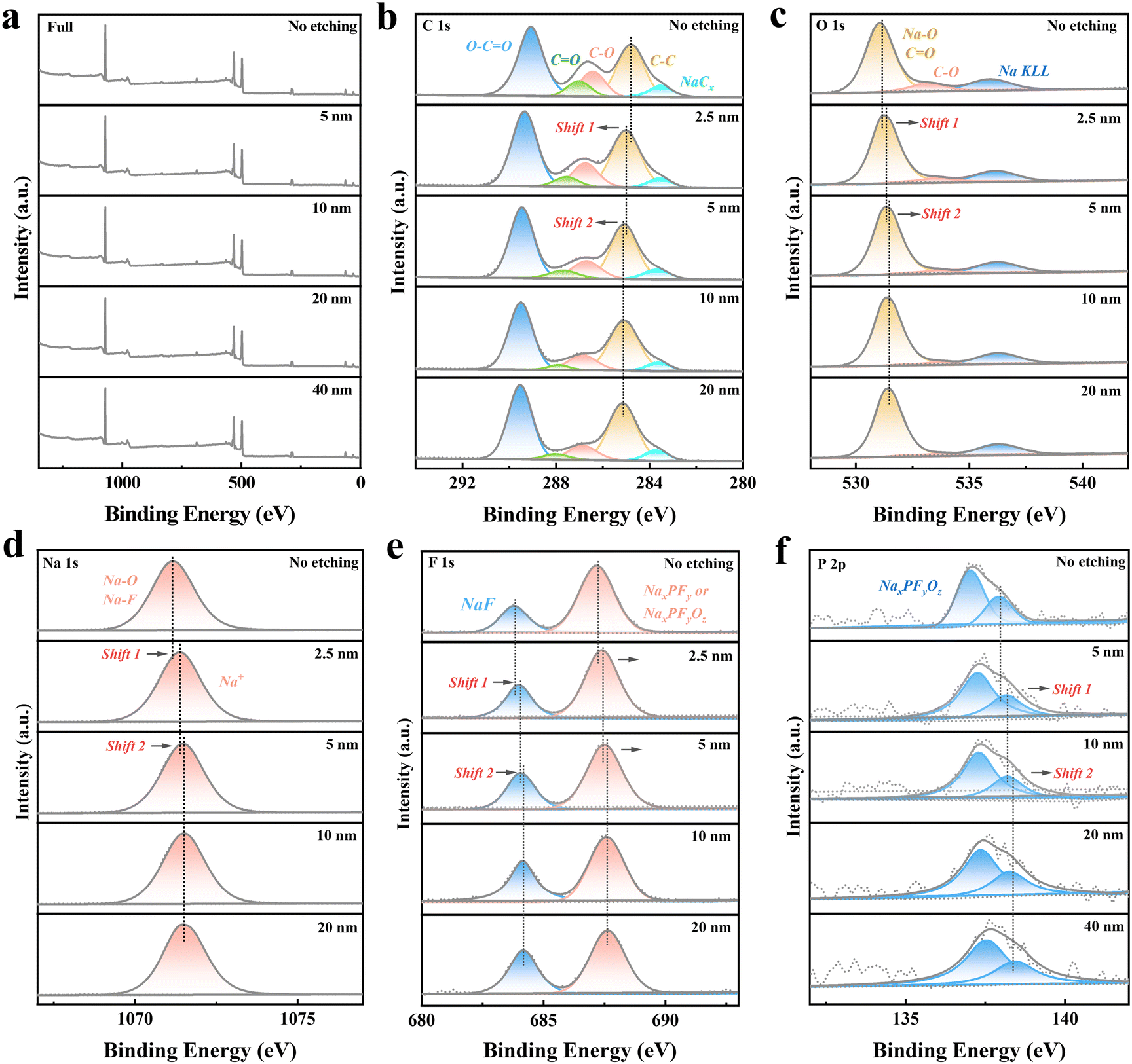 | ||
| Fig. 4 Ex situ XPS analysis of the electrode after 10 activation cycles and charging to 2.5 V. (a) Full XPS spectra obtained at various etching depths. (b)–(f) High-resolution XPS spectra of C 1s, O 1s, F 1s, Na 1s, and P 2p recorded at different etching depths, illustrating the evolution of surface and bulk chemical states in the solid electrolyte interphase (SEI). | ||
Inorganic components, critical for the SEI's functionality, are identified in the F 1s and P 2p spectra.64 The F 1s spectra (Fig. 4d) show peaks for NaF and NaPF6-derived products (e.g., NaPxFyOz), while the P 2p spectra (Fig. 4f) confirm the presence of NaPF6 decomposition products and residuals.65 These inorganic species dominate the inner SEI layer, forming a dense, ionically conductive matrix that facilitates Na+ transport and suppresses further electrolyte decomposition.66 Supporting this, the Na 1s spectra (Fig. 4e) display peaks corresponding to Na+ in Na2O, NaF, and organic sodium compounds. A red shift in Na 1s binding energy with an increasing etching depth reflects a transition from the organic-rich outer SEI layer to the inorganic-rich inner layer, where Na+ is primarily coordinated with species such as NaF and Na2O.
The compositional stratification of the SEI is essential for its functionality. The organic-rich outer layer, composed mainly of carbonates, enhances the SEI's flexibility, allowing it to accommodate volume changes during cycling. In contrast, the inorganic-rich inner layer, primarily consisting of NaF, Na2O, and NaPxFyOz, provides mechanical strength and ionic conductivity, ensuring the SEI's stability and integrity throughout long-term cycling.67 This balanced structure ensures the SEI's ability to passivate the electrode surface, suppress side reactions, and maintain Na+ transport, which are critical for optimizing electrochemical performance.
The formation of this uniform and stratified SEI layer minimizes irreversible capacity loss, reduces interfacial resistance, and contributes to the electrode's high initial Coulombic efficiency and excellent cycling stability.68 The inner inorganic layer enhances Na+ transport, while the outer organic layer ensures compatibility with the electrolyte, mitigating interfacial degradation. These results underscore the importance of optimizing the SEI composition and thickness through electrolyte formulation and cycling protocols to achieve stable long-term performance in sodium-ion batteries.
Overall, the ex situ XPS analysis highlights the crucial role of the SEI in stabilizing the electrode–electrolyte interface, mitigating capacity fade, and enabling robust cycling stability. These findings provide a clear direction for future efforts to improve SEI properties and enhance the performance of sodium-ion battery systems.
To comprehensively understand the sodium storage mechanisms and their evolution with voltage, a combination of ex situ and in situ techniques was employed, including Raman spectroscopy, XRD, EIS, and XPS. The results reveal distinct 3-stage sodium storage stages—absorption, intercalation, and pore-filling—each contributing to the high capacity and stable performance of the electrode material.
Stage 1 (2.5–0.5 V): defect adsorption and surface interaction
During the initial discharge stage (2.5–0.5 V), sodium storage is dominated by rapid adsorption of Na+ onto surface defects and oxygen-containing functional groups.69 GITT analysis indicates a high diffusion coefficient (∼10−9.5 cm2 s−1), consistent with a fast adsorption mechanism.70Ex situ Raman spectra (Fig. 5a) show a decrease in the D-band intensity and a narrowing of the D and G bands, indicating sodium ions occupying defect sites. XRD results (Fig. 5b) show no significant shifts in the carbon peaks, suggesting minimal structural changes. The Nyquist plots (Fig. 5c and Fig. S3 and S4, ESI†) reveal small and stable charge transfer resistance (Rct), confirming efficient charge transfer without the onset of intercalation. Additionally, ex situ XPS C 1s spectra reveals a transformation of CO to C–O bonds, suggesting the involvement of carbonyl oxygen groups in sodium storage through the formation of C–O–Na species.71 This process contributes to the capacity and highlights the role of defect engineering in enhancing sodium adsorption.
 | ||
| Fig. 5 Comprehensive characterization of sodium storage mechanisms in the electrode material. (a) Ex situ Raman spectra at different discharge voltages, highlighting structural evolution during sodium storage. (b) Ex situ XRD patterns showing phase changes with varying discharge voltages. (c) In situ EIS Nyquist plots obtained during the discharge process. (d) Variations of the ohmic resistance (Rs) with the discharge voltage. (e) Variations of the charge transfer resistance (Rct) with the discharge voltage. (f) and (g) Ex situ XPS spectra of C 1s and Na 1s at different discharge voltages (2.5 V, 0.5 V, 0.1 V, and 0.01 V), revealing the chemical evolution of carbon and sodium species. (h) Schematic diagram of the 3-stage sodium storage mechanism. | ||
Stage 2 (0.5–0.05 V): transition to limited intercalation
As the voltage decreases to 0.5–0.05 V, sodium storage transitions to a mechanism dominated by limited intercalation into pseudo-graphitic layers, with continued defect adsorption.72 GITT results show a drop in the diffusion coefficient (∼10−10.5 cm2 s−1), reflecting slower ion transport during intercalation. Raman spectra (Fig. 5a) reveal further decreases in D and G band intensities, albeit at a slower rate, indicating gradual occupation of interlayer spaces by sodium ions. XRD patterns (Fig. 5b) show minimal shifts in the (002) peak position, suggesting limited structural expansion during intercalation.73 The Rct values (Fig. 5e) increase significantly in this stage, reflecting the onset of intercalation as sodium ions migrate through the SEI and enter the carbon matrix. Ex situ XPS analysis further confirms this transition, with an increase in NaCx species detected in the C 1s spectra.74 Additionally, the Na 1s spectra show a slight blue shift in binding energy, indicating the formation of sodium–carbon compounds and a partial reduction of Na+ to metallic sodium (Na0), consistent with the intercalation mechanism.Stage 3 (0.05–0.01 V): sodium cluster formation in pores
At deep discharge voltages (0.05–0.01 V), sodium storage transitions to a pore-filling mechanism characterized by the formation of sodium clusters within the material's pores.75 GITT analysis shows a rebound in the diffusion coefficient (∼10−9 cm2 s−1), reflecting rapid sodium accumulation. Raman spectra (Fig. 5a) reveal new peaks associated with sodium clusters, confirming their formation. Ex situ XPS Na 1s spectra (Fig. 5g) show a further shift in binding energy toward values characteristic of metallic sodium, indicating the quasi-metallic nature of the clusters. Corresponding changes in the C 1s spectra (Fig. 5f) suggest strong interactions between sodium clusters and the carbon matrix. The Nyquist plots (Fig. 5c) show a stabilization and subsequent decrease in Rct (Fig. 5e), indicating that charge transfer is now dominated by the pore-filling process rather than intercalation.76,77 The Rs remains stable throughout, confirming that the electrolyte conductivity is unaffected during this stage. This pore-filling mechanism accounts for the material's high low-voltage capacity, contributing significantly to its overall energy density.Fig. 5h summarizes the sodium storage mechanisms across these stages. At higher voltages, sodium ions are rapidly adsorbed onto defects and functional groups on the carbon surface. As the voltage decreases, intercalation into pseudo-graphitic layers becomes dominant, supported by the material's limited interlayer spacing. Finally, at deep discharge voltages, sodium clusters form within the pores, filling the remaining storage sites and contributing to the high capacity. These findings highlight the importance of optimizing the defect density, interlayer spacing, and pore structure to enhance sodium storage capacity and cycling performance in carbon-based materials.
The electrochemical performance of the ZnO-templated porous hard carbon samples is closely linked to their structural features and synthesis methods. HC-2, fabricated via flash freezing with liquid nitrogen, exhibits the largest specific surface area and the highest sodium storage capacity. Its highly porous structure, dominated by micropores, enhances ion accessibility and transport, resulting in superior rate performance. In contrast, HC-1, produced through gradual freezing, has a moderate surface area and more uniform porosity, offering a balance between capacity and cycling stability. HC-3, synthesized without a freezing step, shows the lowest surface area and a compact, low-porosity structure, leading to poor sodium storage performance.
The cyclic voltammetry (CV) analysis (Fig. 6a), based on the first three scans of HC-2, primarily reveals the formation of a stable SEI layer and identifies the positions of redox peaks. Galvanostatic charge/discharge (GCD) tests demonstrate the exceptional rate capability of HC-2, which maintains a high capacity even at elevated current densities (Fig. 6b and c). Moreover, it exhibits superior rate performance compared to most reported studies utilizing ester-based electrolytes (Fig. 6d).78–85 The microporous structure of HC-2, created by the rapid freezing process, facilitates efficient ion transport and minimizes diffusion resistance.86 HC-1, with its relatively lower surface area, performs well at moderate current densities but shows reduced rate capability. HC-3, due to its compact morphology and limited active sites, suffers from significant capacity loss at higher rates.
 | ||
| Fig. 6 Electrochemical performance of ZnO-templated porous hard carbon samples (HC-1, HC-2, and HC-3). (a) CV (cyclic voltammetry) curves of HC-2 for the first three cycles at a scan rate of 0.1 mV s−1. (b) Rate performance of HC-1, HC-2, and HC-3 at various current densities. (c) GCD (galvanostatic charge–discharge) profiles of HC-1, HC-2, and HC-3 at different discharge rates (0.1–2 A g−1). (d) Rate performance comparison with recently published works. (e) Long-term cycling performance of HC-1, HC-2, and HC-3 at 1 A g−1. | ||
The long-term cycling performance further reflects the structural advantages of the samples. HC-2 demonstrates excellent cycling stability at 1 A g−1 over 1000 cycles with a capacity retention of 75%, attributed to its highly porous structure and the formation of a robust SEI layer. The ex situ XPS analysis confirms that the SEI on HC-2 is thin, stable, and chemically stratified, effectively reducing interfacial resistance and enhancing high-current cycling stability. In comparison, HC-1 exhibits moderate cycling stability, while HC-3 shows rapid capacity fading due to its compact structure and insufficient SEI formation.
These results highlight the critical role of synthesis strategies in optimizing the structural and electrochemical properties of hard carbon. Flash freezing with liquid nitrogen (HC-2) significantly enhances microporosity and surface areas, enabling exceptional rate performance and cycling stability. Gradual freezing (HC-1) offers a compromise between capacity and structural uniformity, while the absence of a freezing step (HC-3) leads to poor sodium storage performance. These findings emphasize the importance of tailoring pore structures and surface chemistry to achieve high-performance sodium-ion batteries.
The full sodium-ion battery assembled using the HC-2 anode and the Na3V2(PO4)3 cathode exhibited good electrochemical performance. Fig. 7a illustrates the charge–discharge profiles of the full cell at various current densities. At 0.02 A g−1, the full cell delivered a high discharge capacity of 96.4 mA h g−1, demonstrating excellent energy storage capability and low polarization. Even at higher current densities, such as 2 A g−1, the cell retained a reasonable discharge capacity of 38.2 mA h g−1, reflecting the anode's robust sodium-ion storage dynamics and stable electrode kinetics.
 | ||
| Fig. 7 (a) Schematic illustration of the HC-2//Na3V2(PO4)3 full sodium-ion battery configuration. (b) Charge–discharge profiles of the full cell at various current densities ranging from 0.02 A g−1 to 2 A g−1. (c) Long-term cycling performance of the full cell at 0.02 A g−1. | ||
The long-term cycling performance of the full cell, as shown in Fig. 7c, further highlights its durability. Operated at 0.02 A g−1, the cell retained 67.3% of its initial capacity after 100 cycles, with a high Coulombic efficiency exceeding 99%. The stable cycling performance is attributed to the porous structure of the HC-2 anode, which accommodates volume expansion during cycling and maintains a stable electrode–electrolyte interface. These results suggest that the integration of the HC-2 anode with the Na3V2(PO4)3 cathode provides a promising approach for high-performance sodium-ion batteries.
Conclusions
This study presents an innovative synthesis method combining liquid nitrogen quenching, freeze-drying, and rapid carbonization, with ZnO derived from zinc gluconate decomposition serving as a template to etch the carbon matrix. This approach successfully produces porous hard carbon materials with high specific surface areas and well-developed pore structures. Notably, HC-2, prepared via liquid nitrogen quenching, achieves the highest specific surface area (532.69 m2 g−1) and optimal porosity, demonstrating the effectiveness of this strategy. The sodium storage mechanisms of the porous hard carbon were thoroughly investigated, revealing three distinct stages: surface adsorption, intercalation into pseudo-graphitic layers, and pore-filling with sodium clusters. The high porosity and oxygen functional groups in HC-2 enhance sodium ion accessibility, improve electrolyte wettability, and facilitate the formation of a stable solid electrolyte interphase (SEI). These features enable HC-2 to achieve superior sodium storage performance, including high capacity, excellent rate capability, and long-term cycling stability. This work highlights a novel and efficient method for creating high-porosity hard carbon materials and provides detailed insights into their sodium storage mechanisms. The findings emphasize the critical role of pore structure optimization and surface chemistry in balancing adsorption, intercalation, and pore-filling processes, offering a valuable strategy for designing advanced hard carbon electrodes for sodium-ion batteries. This research provides an important foundation for developing next-generation energy storage materials.Author contributions
Yulin MAO and Yueyang WANG contributed equally to this work. The manuscript was written through contributions of all authors. All authors have given approval to the final version of the manuscript.Data availability
The data supporting this article has been included as part of the ESI.†Conflicts of interest
There are no conflicts to declare.Acknowledgements
This work was funded by the National Natural Science Foundation of China, Excellent Young Scientists Fund (HK&Macau) (File no. 52122001), the Science and Technology Development Fund, Macao SAR (File no. 0040/2022/A1, FDCT-0082/2021/A2, 0010/2022/AMJ, 0060/2023/RIA1, 0136/2022/A3, 006/2022/ALC, 0122/2024/AMJ, and EF044/IAPME-HG/2022/MUST), the Multi-Year Research Grant from the University of Macau (File no. MYRG-CRG2023-00009-IAPME), the Wuyi University-Hong Kong-Macau Joint Research and Development Fund (File no. 2022WGALH04), the Jilin Province Transportation Innovation and Development Support Project (File no. 2024-1-5) and the Zhuhai Transportation Holdings Group Co., Ltd Science and Technology Project (File no. JT-KT202401).References
- Y. Li, A. Vasileiadis, Q. Zhou, Y. Lu, Q. Meng, Y. Li, P. Ombrini, J. Zhao, Z. Chen, Y. Niu, X. Qi, F. Xie, R. van der Jagt, S. Ganapathy, M.-M. Titirici, H. Li, L. Chen, M. Wagemaker and Y.-S. Hu, Nat. Energy, 2024, 9, 134–142 CrossRef CAS.
- J.-M. Tarascon, Joule, 2020, 4, 1616–1620 CrossRef.
- Z. Cheng, H. Zhang, J. Cui, J. Zhao, S. Dai, Z. Zhang, K. Song, S. Wang, Y. Yuan, Q. Chen, X. Kong, L. Qie, L. Yuan, H. Yang, S. Zhu, Y. Fang, Y. Huang and Y. Yao, Joule, 2025, 101812 CrossRef.
- Z. Lu, H. Yang, Y. Guo, H. Lin, P. Shan, S. Wu, P. He, Y. Yang, Q.-H. Yang and H. Zhou, Nat. Commun., 2024, 15, 3497 CrossRef CAS PubMed.
- B. Wang, J. R. Fitzpatrick, A. Brookfield, A. J. Fielding, E. Reynolds, J. Entwistle, J. Tong, B. F. Spencer, S. Baldock, K. Hunter, C. M. Kavanagh and N. Tapia-Ruiz, Nat. Commun., 2024, 15, 3013 CrossRef CAS PubMed.
- X. Fan, X. Kong, P. Zhang and J. Wang, Energy Storage Mater., 2024, 69, 103386 CrossRef.
- Y. Gao, Q. Yu, H. Yang, J. Zhang and W. Wang, Adv. Mater., 2024, 36, 2405989 CrossRef CAS PubMed.
- H. Zhang, L. Song, S. Lin, Z. Huang, C. Shu, Y. Ma, Z. Tang, X. Wang, W. Tang and Y. Wu, Energy Storage Mater., 2024, 73, 103796 CrossRef.
- A. Mehmood, G. Ali, B. Koyutürk, J. Pampel, K. Y. Chung and T.-P. Fellinger, Energy Storage Mater., 2020, 28, 101–111 CrossRef.
- D. Igarashi, Y. Tanaka, K. Kubota, R. Tatara, H. Maejima, T. Hosaka and S. Komaba, Adv. Energy Mater., 2023, 13, 2302647 CrossRef CAS.
- K. Sada, J. Darga and A. Manthiram, Adv. Energy Mater., 2023, 13, 2302321 CrossRef CAS.
- S. Alvin, D. Yoon, C. Chandra, H. S. Cahyadi, J.-H. Park, W. Chang, K. Y. Chung and J. Kim, Carbon, 2019, 145, 67–81 CrossRef CAS.
- Y. Huang, X. Zhong, X. Hu, Y. Li, K. Wang, H. Tu, W. Deng, G. Zou, H. Hou and X. Ji, Adv. Funct. Mater., 2024, 34, 2308392 CrossRef CAS.
- C. Liu, Q. Lu, J. Qu, W. Feng, A. Thomas, Y. Li, I. G. G. Martinez, C. Pan and D. Mikhailova, Small, 2024, 20, 2311253 CrossRef CAS PubMed.
- C. Liu, Q. Lu, M. V. Gorbunov, A. Omar, I. G. Gonzalez Martinez, P. Zhao, M. Hantusch, A. Dimas Chandra Permana, H. He, N. Gaponik and D. Mikhailova, J. Energy Chem., 2023, 79, 373–381 CrossRef CAS.
- N. Sun, J. Qiu and B. Xu, Adv. Energy Mater., 2022, 12, 2200715 CrossRef CAS.
- N. Lan, Y. Shen, J. Li, H. He and C. Zhang, Adv. Mater., 2024, 2412989 CrossRef PubMed.
- H. Zhou, Y. Song, B. Zhang, H. Sun, I. A. Khurshid, Y. Kong, L. Chen, L. Cui, D. Zhang, W. Wang, L. Yang and X. Du, Energy Storage Mater., 2024, 71, 103645 CrossRef.
- A. Kamiyama, K. Kubota, D. Igarashi, Y. Youn, Y. Tateyama, H. Ando, K. Gotoh and S. Komaba, Angew. Chem., Int. Ed., 2021, 60, 5114–5120 CrossRef CAS PubMed.
- H. He, J. He, H. Yu, L. Zeng, D. Luo and C. Zhang, Adv. Energy Mater., 2023, 13, 2300357 CrossRef CAS.
- P. Strubel, S. Thieme, T. Biemelt, A. Helmer, M. Oschatz, J. Brückner, H. Althues and S. Kaskel, Adv. Funct. Mater., 2015, 25, 287–297 CrossRef CAS.
- C. Wen, M. Huang, C. Feng, N. Kong, K. Hou, R. Xie, Z. Shao, R. Tan and F. Han, Carbon, 2024, 230, 119702 CrossRef CAS.
- S. Huang, Y. Lv, W. Wen, T. Xue, P. Jia, J. Wang, J. Zhang and Y. Zhao, Mater. Today Energy, 2021, 20, 100673 CrossRef CAS.
- W. Li, J. Li, B. W. Biney, Y. Yan, X. Lu, H. Li, H. Liu, W. Xia, D. Liu, K. Chen and A. Guo, Energy Storage Mater., 2025, 74, 103867 CrossRef.
- Y. Liu, J. Yin, R. Wu, H. Zhang, R. Zhang, R. Huo, J. Zhao, K.-Y. Zhang, J. Yin, X.-L. Wu and H. Zhu, Energy Storage Mater., 2025, 75, 104008 Search PubMed.
- L. Zhou, Y. Cui, P. Niu, L. Ge, R. Zheng, S. Liang and W. Xing, Carbon, 2025, 231, 119733 CrossRef CAS.
- S. You, Q. Zhang, J. Liu, Q. Deng, Z. Sun, D. Cao, T. Liu, K. Amine and C. Yang, Energy Environ. Sci., 2024, 17, 8189–8197 RSC.
- B. Wang, S. Zhang, X. Jia, F. Yuan, H. Sun, Z. Li, Q. Sun, Q. Wang and D. Zhang, Chem. Eng. J., 2024, 499, 156126 Search PubMed.
- Y. Wang, X. Wang, B. Zhao, Z. Ren, Z. Yao, W. Wei, J. Wang, J. Qin, J. Xie and M. Cao, Nano Energy, 2024, 120, 109163 CrossRef CAS.
- X. Zhang, M. Zhao, X. Zhai, X. Sun, S. Cheng and H. Li, Small Methods, 2024, 2400865 CrossRef PubMed.
- J. Li, J. Hao, Q. Yuan, R. Wang, F. Marlton, T. Wang, C. Wang, X. Guo and G. Wang, Carbon Energy, 2024, 6, e518 Search PubMed.
- B. Wang, Y. Yao, W. Wang, Y. Xu, Y. Sun, Q. Li, H. Hu and M. Wu, Chem. Eng. J., 2024, 488, 151055 CrossRef CAS.
- Z. Lu, J. Wang, W. Feng, X. Yin, X. Feng, S. Zhao, C. Li, R. Wang, Q.-A. Huang and Y. Zhao, Adv. Mater., 2023, 35, 2211461 CrossRef CAS PubMed.
- Y. Li, Y. Lu, Q. Meng, A. C. S. Jensen, Q. Zhang, Q. Zhang, Y. Tong, Y. Qi, L. Gu, M.-M. Titirici and Y.-S. Hu, Adv. Energy Mater., 2019, 9, 1902852 CrossRef CAS.
- B. Xing, F. Shi, Z. Jin, H. Zeng, X. Qu, G. Huang, C. Zhang, Y. Xu, Z. Chen and J. Lu, Carbon Energy, 2024, e633 CrossRef CAS.
- Y. Zhang, L. Gong, X. Xu, L. Zhao, K. Li, G. Liang, L. Li and Q. Xie, Carbon, 2024, 216, 118487 CrossRef CAS.
- S. Storck, H. Bretinger and W. F. Maier, Appl. Catal., A, 1998, 174, 137–146 CrossRef CAS.
- X. Chen, J. Tian, P. Li, Y. Fang, Y. Fang, X. Liang, J. Feng, J. Dong, X. Ai, H. Yang and Y. Cao, Adv. Energy Mater., 2022, 12, 2200886 CrossRef CAS.
- Y. Zhou, Y. Wang, C. Fu, J. Zhou, Y. Song, S. Lin, S. Liang, S. Zhou and A. Pan, Small, 2024, 20, 2405921 Search PubMed.
- G. Duan, J. Xiao, L. Chen, C. Zhang, S. Jian, S. He and F. Wang, J. Energy Storage, 2023, 67, 107559 CrossRef.
- H. Xiong, H. Liu, X. Feng, Y. Sun, Q. Huang and C. Xiao, Carbon, 2024, 229, 119547 CrossRef CAS.
- G. Lee, K. B. Min, M. E. Lee, Y.-K. Lee, H. R. Lee, S.-S. Kim, S. Y. Cho, H.-I. Joh, Y.-K. Kim and S. Lee, Chem. Eng. J., 2024, 479, 147766 CrossRef CAS.
- Y. Zhao, Z. Hu, W. Zhou, P. Gao, Z. Liu, J. Liu, C. Fan and J. Liu, Adv. Funct. Mater., 2024, 34, 2405174 CrossRef CAS.
- Z. Song, M. Di, X. Zhang, Z. Wang, S. Chen, Q. Zhang and Y. Bai, Adv. Energy Mater., 2024, 14, 2401763 CrossRef CAS.
- A. Yu, Y. Zhao, W. Zhang, W. Yang, L. Zhu, P. Peng, F.-F. Li and Y. Yang, Adv. Funct. Mater., 2024, 34, 2309666 CrossRef CAS.
- Q. Hu, L. Xu, G. Liu, J. Hu, X. Ji and Y. Wu, ACS Nano, 2024, 18, 21491–21503 CrossRef CAS PubMed.
- Z.-h Ma, T. Yang, Y. Song, X.-d Tian, Z.-y Liu, X.-j Gong and Z.-j Liu, J. Colloid Interface Sci., 2024, 661, 436–449 CrossRef CAS PubMed.
- X.-W. Gao, Q. Li, R. Yang, Y. Song, Z.-M. Liu, Q. Gu and W.-B. Luo, ACS Appl. Energy Mater., 2024, 7, 7829–7837 CrossRef CAS.
- K.-Y. Zhang, H.-H. Liu, J.-M. Cao, J.-L. Yang, M.-Y. Su, X.-Y. Wang, Z.-Y. Gu, J. Wang, B. Li, Y. Wang and X.-L. Wu, Energy Storage Mater., 2024, 73, 103839 CrossRef.
- Z. Zeng, B.-A. Mei, G. Song, M. Hamza, Z. Yan, Q. Wei, H. Feng, Z. Zuo, B. Jia and R. Xiong, J. Energy Storage, 2024, 102, 114021 CrossRef.
- M. Li, Z. Li, H. Song, N. Harudin, M. Z. Kufian, H. J. Woo and Z. Osman, J. Power Sources, 2025, 625, 235685 Search PubMed.
- Q. Zhang, P. Yue, M. Jia, J. Jia, Y. Ren, G. Li, J. Sun, L. Hou, M. Chen and C. Yuan, Chem. Eng. J., 2024, 500, 156779 CrossRef CAS.
- Y. Fang, L. Li, J. Li, Y. Gan, J. Du, J. Li, X. Chen, H. Pan, W. Zhang, J. Gu, D. Zhang and Q. Liu, Adv. Funct. Mater., 2024, 34, 2408568 CrossRef CAS.
- H. Zheng, D. Ma, M. Pei, C. Lin, Y. Liu, S. Deng, R. Qiu, Y. Luo, W. Yan and J. Zhang, Adv. Funct. Mater., 2024, 2411651 Search PubMed.
- Y. Aniskevich, J. H. Yu, J.-Y. Kim, S. Komaba and S.-T. Myung, Adv. Energy Mater., 2024, 14, 2304300 CrossRef CAS.
- R. Cui, Y. Ma, X. Gao, W. Wang, J. Wang, Z. Xing and Z. Ju, Energy Storage Mater., 2024, 71, 103627 CrossRef.
- S. Zhang, N. Sun, X. Li, R. A. Soomro and B. Xu, Energy Storage Mater., 2024, 66, 103183 CrossRef.
- Y. Huang, Q. Zhang, X.-G. Sun, K. Liu, W. Sun, M. Zhi, Y. Guo, S. Zheng and S. Dai, Angew. Chem., Int. Ed., 2024, 63, e202406277 CrossRef CAS PubMed.
- Z. Xu, R. Li, G. Xie, D. Qian, H. Fang and Z. Wang, Energy Storage Mater., 2024, 66, 103195 CrossRef.
- D. Schäfer, K. Hankins, M. Allion, U. Krewer, F. Karcher, L. Derr, R. Schuster, J. Maibach, S. Mück, D. Kramer, R. Mönig, F. Jeschull, S. Daboss, T. Philipp, G. Neusser, J. Romer, K. Palanisamy, C. Kranz, F. Buchner, R. J. Behm, A. Ahmadian, C. Kübel, I. Mohammad, A. Samoson, R. Witter, B. Smarsly and M. Rohnke, Adv. Energy Mater., 2024, 14, 2302830 CrossRef.
- Z. Guo, M. Yang, Q. Fan, Y. Chen, T. Xu, C. Li, Z. Li, Z. Li, Q. Sun and H. Xia, Small, 2024, 2407425 CrossRef CAS PubMed.
- J.-L. Li, Y.-N. Wang, S.-Y. Sun, Z. Zheng, Y. Gao, P. Shi, Y.-J. Zhao, X. Li, Q. Li, X.-Q. Zhang and J.-Q. Huang, Adv. Energy Mater., 2024, 2403845 Search PubMed.
- Z. Wang, H. Yang, Y. Liu, Y. Bai, G. Chen, Y. Li, X. Wang, H. Xu, C. Wu and J. Lu, Small, 2020, 16, 2003268 Search PubMed.
- R. Mogensen, D. Brandell and R. Younesi, ACS Energy Lett., 2016, 1, 1173–1178 CrossRef CAS.
- K. Cui, R. Hou, H. Zhou and S. Guo, Adv. Funct. Mater., 2024, 2419275 Search PubMed.
- H. Yildirim, A. Kinaci, M. K. Y. Chan and J. P. Greeley, ACS Appl. Mater. Interfaces, 2015, 7, 18985–18996 Search PubMed.
- M. Hou, Y. Zhou, F. Liang, H. Zhao, D. Ji, D. Zhang, L. Li and Y. Lei, Chem. Eng. J., 2023, 475, 146227 CrossRef CAS.
- Y. Wan, K. Song, W. Chen, C. Qin, X. Zhang, J. Zhang, H. Dai, Z. Hu, P. Yan, C. Liu, S. Sun, S.-L. Chou and C. Shen, Angew. Chem., Int. Ed., 2021, 60, 11481–11486 CrossRef CAS PubMed.
- J. Li, C. Liu, X. Hu, J. Cai, H. Lian, D. Li, B. Zhong, W. Deng, H. Hou, G. Zou and X. Ji, Adv. Funct. Mater., 2024, 2417059 Search PubMed.
- B. Lu, J.-X. Song, D.-R. Deng, G.-F. Li, Y. Zeng, S.-L. Cai, J.-C. Weng, X.-H. Fan, Y. Li and Q.-H. Wu, J. Energy Storage, 2024, 102, 114056 CrossRef.
- G. Zhao, T. Xu, Y. Zhao, Z. Yi, L. Xie, F. Su, Z. Yao, X. Zhao, J. Zhang, W. Xie, X. Li, L. Dong and C.-M. Chen, Energy Storage Mater., 2024, 67, 103282 CrossRef.
- Y. Liu, X. Guo, X. Liu, D. Huang, X. Tian, Q. Guo and Z. Liu, J. Colloid Interface Sci., 2024, 675, 870–882 CrossRef CAS PubMed.
- N. Lege, Y. Zhang, W. Lai, X. He, Y.-X. Wang, L. Zhao, M. Liu, X. Wu and S. Chou, Chem. Sci., 2025, 16, 1179–1188 RSC.
- J. Jiao, H. Lu, C. Yi, D. Yang, X. Zeng, J. Lin and H. Li, Chem. Eng. J., 2024, 500, 156878 CrossRef CAS.
- C. Qiu, A. Li, D. Qiu, Y. Wu, Z. Jiang, J. Zhang, J. Xiao, R. Yuan, Z. Jiang, X. Liu, X. Chen and H. Song, ACS Nano, 2024, 18, 11941–11954 CrossRef CAS PubMed.
- C. Wang, A. J. Appleby and F. E. Little, Electrochim. Acta, 2001, 46, 1793–1813 CrossRef CAS.
- L. Tian, Q. Zhuang, J. Li, Y. Shi, J. Chen, F. Lu and S. Sun, Chin. Sci. Bull., 2011, 56, 3204–3212 CrossRef CAS.
- Y.-E. Zhu, L. Yang, X. Zhou, F. Li, J. Wei and Z. Zhou, J. Mater. Chem. A, 2017, 5, 9528–9532 RSC.
- P. Bai, Y. He, P. Xiong, X. Zhao, K. Xu and Y. Xu, Energy Storage Mater., 2018, 13, 274–282 CrossRef.
- B. Xiao, F. A. Soto, M. Gu, K. S. Han, J. Song, H. Wang, M. H. Engelhard, V. Murugesan, K. T. Mueller, D. Reed, V. L. Sprenkle, P. B. Balbuena and X. Li, Adv. Energy Mater., 2018, 8, 1801441 CrossRef.
- P. Bai, X. Han, Y. He, P. Xiong, Y. Zhao, J. Sun and Y. Xu, Energy Storage Mater., 2020, 25, 324–333 CrossRef.
- Q. Jin, K. Wang, H. Li, W. Li, P. Feng, Z. Zhang, W. Wang, M. Zhou and K. Jiang, Chem. Eng. J., 2021, 417, 128104 CrossRef CAS.
- M. Ma, H. Cai, C. Xu, R. Huang, S. Wang, H. Pan and Y.-S. Hu, Adv. Funct. Mater., 2021, 31, 2100278 CrossRef CAS.
- G. Liu, Z. Wang, H. Yuan, C. Yan, R. Hao, F. Zhang, W. Luo, H. Wang, Y. Cao, S. Gu, C. Zeng, Y. Li, Z. Wang, N. Qin, G. Luo and Z. Lu, Adv. Sci., 2023, 10, 2305414 CrossRef CAS PubMed.
- S. Manna, P. Verma and S. Puravankara, J. Power Sources, 2025, 631, 236234 CrossRef CAS.
- X. Feng, Y. Li, Y. Li, M. Liu, L. Zheng, Y. Gong, R. Zhang, F. Wu, C. Wu and Y. Bai, Energy Environ. Sci., 2024, 17, 1387–1396 RSC.
Footnotes |
| † Electronic supplementary information (ESI) available. See DOI: https://doi.org/10.1039/d5nj00770d |
| ‡ Yulin Mao and Yueyang Wang contributed equally. |
| This journal is © The Royal Society of Chemistry and the Centre National de la Recherche Scientifique 2025 |