
 Open Access Article
 This Open Access Article is licensed under a
 Creative Commons Attribution 3.0 Unported Licence
Grain boundaries in periodic vs. in aperiodic crystals composed of colloids with preferred binding angles
Robert F. B.
Weigel
 and
Michael
Schmiedeberg
*
and
Michael
Schmiedeberg
*
Theoretical Physics: Lab for Emergent Phenomena, Friedrich-Alexander-Universität, Erlangen-Nürnberg, 91058 Erlangen, Germany. E-mail: michael.schmiedeberg@fau.de
First published on 18th June 2025
Abstract
Using a modified phase field crystal model that we have recently introduced [Weigel et al., Modelling and Simulation in Materials Science and Engineering, 2022, 30, 074003], we study grain boundaries that occur in two-dimensional structures composed of particles with preferred binding angles like patchy colloids. In the case of structures with a triangular order, we show how particles with a 5-fold rotational symmetry that differs from the usual 6-fold coordination of a particle in bulk affect the energy of the dislocations in the grain boundaries. Furthermore, for quasicrystals we find that the dislocation pairs recombine easily and the grain boundaries disappear. However, the resulting structure usually possesses a lot of phasonic strain. Our results demonstrate that the preferred symmetry of a particle is important for grain boundaries, and that periodic and aperiodic structures may differ in how stable their domain boundaries are.
Design, System, ApplicationWe perform calculations with a phase field crystal model of particles with preferred binding angles. The system is described by a density-like field that gives the relative deviation from a homogeneous density and a complex orientational field that contains both the strength of the orientation and a phase to denote the angle with respect to some reference direction. The phase field crystal approach uses a functional that corresponds to a power law expansion of the free energy that we minimize in our calculations. We seed grains with different orientations and study the free energy and the number of dislocations as a function of the angle between the seeded grains. For periodic crystals, we are especially interested in those composed of particles that possess a 5-fold rotational symmetry and find that they do not affect the dependence of the free energy on the angle between the grains. However, if quasicrystalline grains are considered, the outcome is totally different from that of periodic crystals as dislocations recombine. |
Patchy colloids are particles whose surface is decorated such that there are special binding sites (see, e.g., ref. 1). These sites might be either attractive or repulsive. As a result, patchy colloids possess preferred binding angles such that they can organize into a large variety of complex structures (see, e.g., ref. 2 and 3).
Recently, we have developed a phase field crystal model to describe the phase behavior of particles with preferred binding angles.4 Phase field crystal theories5,6 are based on the expansion of the free energy similar to that in the Swift–Hohenberg approach,7,8 can be derived from microscopic theories,9,10 and have been proposed to study the phase behavior in two dimensions.5,6 A similar approach had been introduced to explain the stability of quasicrystals.11,12
Quasicrystals possess a long range order but no translational symmetry. They were first reported in a physical system by Dan Shechtman.13 In the meantime, there are also many soft matter systems where quasicrystals have been observed.14–18 There are special collective rearrangements called phasons that occur in quasicrystals, which – similar to phonons in a crystal – do not increase the free energy;19,20 quasicrystals differ from periodic crystals, for e.g., in their growth behaviour21,22 and in how grain boundaries are formed or might disappear.23,24 Quasicrystals are also expected to occur for systems composed of patchy colloids.25–30
In this paper, we study grain boundaries in both periodic and aperiodic crystals composed of particles with preferred binding angles.
1 Model system
To denote the preferred binding angles in our phase field crystal approach,4 we consider particles with a given n-fold rotational symmetry. Our approach is motivated by the phase field crystal model of particles with axial symmetry.31The system is described by a density-like field ψ that gives the relative deviation from a homogeneous density; thus its mean is 0. Furthermore, there is a complex orientational field U that contains both the strength |U| of the orientation and a phase to give the angle with respect to some reference direction. A homogeneous state is represented by ψ = 0 and a constant U. A state with isotropic orientation has a vanishing U = 0.
The free energy functional of our phase field crystal approach was derived in ref. 4 and is given by
 | (1) |
The phase behavior has been discussed in ref. 4. Note that as usual for the phase field crystal or similar models the resulting structures correspond to periodic or aperiodic cluster crystals.4,34
As we consider grain boundaries in the triangular phase for n = 2, 5, and ∞ (i.e., isotropic interactions), we choose parameter values for which the triangular phase is stable:4Bl = 3, Bx = 3.5, D = 0.5, and E = 0.5. Furthermore, f(∇2) = ∇6 in order to suppress instabilities.4 Choosing F = 0 results in a vanishing orientation field U = 0. In this sense, F = 0 is equivalent to considering isotropic particles with n = ∞. When considering other values of n, we set F = 1, such that the orientation field plays a role.
The dodecagonal quasicrystalline phase is stable for n = 6, Bl = 3, Bx = 3.5, D = 2, E = 1, and F = 14. In this case, to enhance modulations in the orientation, we have to choose a non-monotonic function for f(∇2), which in reciprocal space has an extended flat minimum at small wave numbers k and for large k, it grows like k8. For further details, please see the discussion in ref. 4.
2 Setup and procedure
We study the behavior of grain boundaries by seeding crystalline grains of different orientations of the lattice lines next to each other. We set the angle α between the grain boundary and the lattice lines symmetrically on both sides of the grain boundary (see Fig. 1a). Due to the 6-fold dihedral symmetry of the triangular lattice, the system is periodic in α with a period of and a mirror symmetry at half the period. Thus, it suffices to consider the range of α ∈
  . The other angle in the triangle formed by the grain boundary and two lattice lines,
  , simultaneously covers the range
  .
.
 | ||
| Fig. 1 (a) Schematic of the orientation of the grains with respect to the grain boundaries and the primitive unit cells. (b) Color map of the initial density-like field consisting of the seeds of the two grains and the Moiré pattern in between. (c) Final density-like field with dislocations highlighted. The 17 peaks with 7 (5) neighbors are marked with a purple (dark green) circle. The orientation field is not visualized. | ||
We interpolate between the two grains with the functions (1 ± cos(![[k with combining right harpoon above (vector)]](https://www.rsc.org/images/entities/i_char_006b_20d1.gif) 0 ·
0 · ![[x with combining right harpoon above (vector)]](https://www.rsc.org/images/entities/i_char_0078_20d1.gif) ))/2 with 0 = dk(cos
))/2 with 0 = dk(cos![[thin space (1/6-em)]](https://www.rsc.org/images/entities/char_2009.gif) γ, sinγ) and dk = 2π/L. As L is the length of the square-shaped simulation box with periodic boundaries, these interpolation functions make just one oscillation across the length of the box. Since the functions are smooth, they do not create a sharp edge between the grains but introduce a Moiré pattern between them instead (see Fig. 1b). Upon minimizing the free energy, the Moiré pattern relaxes to a grain boundary, which may not follow a straight line; see Fig. 1c. The angle γ is the angle between the straight line, where the grain boundary most likely will emerge, and a side of the simulation box. Since the free energy of the system may depend on the orientation of the simulation box relative to the grain boundary or relative to the orientation of the grains themselves, we vary γ when necessary to average over this dependence, effectively tilting the simulation box against the two grains; see Fig. 2. The angle α is always defined relative to the straight line, around which the grains are initialized. Hence, when γ is varied at constant α, both grains rotate relative to the simulation box.
γ, sinγ) and dk = 2π/L. As L is the length of the square-shaped simulation box with periodic boundaries, these interpolation functions make just one oscillation across the length of the box. Since the functions are smooth, they do not create a sharp edge between the grains but introduce a Moiré pattern between them instead (see Fig. 1b). Upon minimizing the free energy, the Moiré pattern relaxes to a grain boundary, which may not follow a straight line; see Fig. 1c. The angle γ is the angle between the straight line, where the grain boundary most likely will emerge, and a side of the simulation box. Since the free energy of the system may depend on the orientation of the simulation box relative to the grain boundary or relative to the orientation of the grains themselves, we vary γ when necessary to average over this dependence, effectively tilting the simulation box against the two grains; see Fig. 2. The angle α is always defined relative to the straight line, around which the grains are initialized. Hence, when γ is varied at constant α, both grains rotate relative to the simulation box.
 | ||
| Fig. 2 Schematic of the grains and grain boundaries tilted by an angle γ against the simulation box. | ||
To obtain statistics, we perform computations for 10 different random initial configurations for each α: both grains' lattices are displaced by independent random vectors drawn from their respective rotated primitive unit cells; see Fig. 1a. The orientation field is initialized as low-amplitude random noise.
For our study regarding the triangular phase, it suffices to not vary γ and keep γ = 0, as shown in section 3.4.
To study grain boundaries in dodecagonal quasicrystals, we initialize the seed of each grain as 12 modes in reciprocal space with equal amplitudes and random phases. Hence, the position of the symmetry center and other degrees of freedom (isomorphism class) are random. In the same range of α ∈  and for 11 values of γ in the inclusive range
  , we perform 10 simulations each.
We freely minimize the free energy with respect to the fields ψ and U by following the negative of the functional derivatives,
 | (2) |
 | (3) |
000 iterations of semi-implicit Euler integration with a step size of 0.03 are enough to reach the local minimum. The global minimum, a single crystal, cannot be reached with simple Euler integration from the initialization with two grains.
With the equilibrium nearest-neighbor peak distance being roughly 2π, we perform simulations in a square box of length L = 24.39 · 2π with periodic boundary conditions, discretized to 512 × 512 points, i.e. with a spatial resolution of 0.0476 · 2π.
When the simulation box is resized, stress might be reduced. The terms proportional to Bx, E, and F are the only ones sensitive to the size, and their reciprocal-space representation is a polynomial in the resolutions dkx and dky. The free energy can be minimized with respect to the resolutions with, for e.g. the Nelder–Mead algorithm.35 We do this to reduce stress once during the simulation, at half the simulation time, after the fields have almost become stationary. Note the size difference between Fig. 1b and c. This step adapts the size of the simulation box or the spatial resolution, respectively. However it does not change the mean density.
3 Results
3.1 Grains align in the nematic phase
The nematic phase – a homogeneous density with a constant finite orientation field – is also stable under some parameters.4,31 To study grain boundaries in the nematic phase, we initialize the orientation field as two grains of different directions and the density-like field as low-amplitude noise. Grains of different nematic orientations eventually align after the energy minimization, leaving no boundaries. Thus, the minimization leads to the global minimum in this case.3.2 Defects of the triangular lattice
Dislocations are topological point defects in two-dimensional lattices. While every peak has 6 neighbor peaks in the regular triangular lattice, a dislocation corresponds to a pair of one peak with only 5 neighbors and another peak with 7 neighbors. Usually, these two are the nearest neighbors to each other. In our model, we observe that 5-coordinated peaks are smaller and 7-coordinated ones are larger in width, compared with the regular 6-coordinated peaks; see Fig. 3.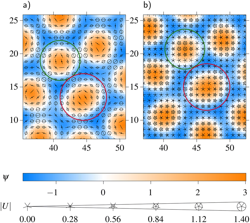 | ||
| Fig. 3 Similar dislocations in configurations obtained with (a) n = 2 and (b) n = 5. The peaks with 7 (5) neighbors are marked with a purple (dark green) circle; all other peaks have 6 neighbors. The orientation field is visualized using markers on top of the density-like field: the size of the circles encodes the magnitude of the orientation field and the direction is indicated by the arms. The spatial resolution of the orientation field is as tight as that of the density-like field; for ease of reading, we only show a few markers. | ||
Dislocations can be created and annihilated in pairs of opposing Burgers vector. However, as we initialize the system without special care for the defect composition, in some configurations an odd number of dislocations is present. Due to the topology, the number of defects must stay odd (or even) under any peak-conserving dynamics. Some dislocations are deformed: it is very hard to tell apart the 5- and 7-coordinated peaks from some of their 6-coordinated neighbors. The Burgers vector reveals that they are normal dislocations nevertheless; see Fig. 4.
 | ||
| Fig. 4 A distorted dislocation. The density-like field and orientation field are visualized as shown in Fig. 3. The open Burgers path around the dislocation is shown in red. | ||
Rarely, we observe disclinations, i.e. peaks with 5 or 7 neighbors surrounded by 6-coordinated neighbors exclusively. They only occur in configurations with many dislocations. Often, they are located close to chains of alternating 5- and 7-coordinated peaks with an odd length. In these cases, it is fundamentally ambiguous to decide which of the ends of the chain belongs to the dislocations and which is from another disclination. For statistics, we count a disclination pair as one dislocation.
3.3 Orientation field matching the lattice
For n = 2, the orientation field vanishes at all peaks, regardless of how many neighbors they have; see Fig. 3a. In contrast, for n = 5, the orientation field still vanishes at the 6- and 7-coordinated peaks, but it is finite – even quite large – at the 5-coordinated peaks; see Fig. 3b. This phenomenon appears to be largely independent of α. Hence, the large orientation field at the peak is not induced by long-ranged interactions between the grains, but rather by the local environment around a 5-coordinated peak.Without this knowledge, but based on the observation of strongly oriented 5-coordinated peaks in uncontrolled grain boundaries, we conjectured in 4 that an orientation between grains matching the 5-fold symmetry may be energetically favored for n = 5. In the next section, we show that our new calculations of the free energy as a function of the angle between grains do not support this conjecture.
3.4 Free energy
First, we establish that the orientation of a single triangular crystal relative to the box has no big influence on the free energy, as is shown by the crosses connected by lines in Fig. 5. A single crystal may be strained, when it is tilted against the box. Thus, its energy may be slightly higher than that of the perfect triangular lattice without strain or defects. We find that the free energies of configurations with grain boundaries and dislocations are considerably higher than those of strained single crystals. Therefore, it is sufficient to consider only γ = 0, i.e. not to vary the tilt between the box and the initial grain boundary. | ||
Fig. 5 The rescaled free energy ![[scr F, script letter F]](https://www.rsc.org/images/entities/char_e141.gif) /|tri| is shown as a function of angle α for different numbers of patches n = 2, 5, and ∞. The cross symbols show the outcomes of independent simulation runs and the surrounding shapes are violin plots, in which the width gives the frequency of the respective value. The free energy is rescaled by the energy tri of the perfect triangular crystal of the respective n, which is given in Table 1. At /|tri| is shown as a function of angle α for different numbers of patches n = 2, 5, and ∞. The cross symbols show the outcomes of independent simulation runs and the surrounding shapes are violin plots, in which the width gives the frequency of the respective value. The free energy is rescaled by the energy tri of the perfect triangular crystal of the respective n, which is given in Table 1. At  and and  , the grains are parallel. Thus, the system easily relaxes to a single crystal with a rescaled energy of −1. Remarkably, however, the data coincide rather well for the different n at any angle α. Additionally, the free energy of a single crystal, rotated by α against the simulation box, is plotted. Also, the number of dislocations Nd takes qualitatively the same course with α as the rescaled energy and Nd are essentially independent of n. The sketches below the α axis illustrate how the lattice lines meet at the grain boundary. The red stars indicate at which α the lattice lines meet compatible with a regular pentagon. , the grains are parallel. Thus, the system easily relaxes to a single crystal with a rescaled energy of −1. Remarkably, however, the data coincide rather well for the different n at any angle α. Additionally, the free energy of a single crystal, rotated by α against the simulation box, is plotted. Also, the number of dislocations Nd takes qualitatively the same course with α as the rescaled energy and Nd are essentially independent of n. The sketches below the α axis illustrate how the lattice lines meet at the grain boundary. The red stars indicate at which α the lattice lines meet compatible with a regular pentagon. | ||
We rescale the energy by the absolute of the free energy of the perfect triangular lattice for the respective n, which is given in Table 1. The rescaled /|tri| of a perfect crystal is −1 and the rescaled free energy of a homogeneous isotropic configuration is still 0. Contrary to our conjecture,  or
or  is not energetically favored for n = 5. Instead, the maximum rescaled free energy occurs roughly at
  , as the data in Fig. 5 show. The situation is almost identical for all considered n, up to the constant rescaling factors and a slightly smaller increase of the free energy in the case of n = 5 in comparison to the increase for isotropic interactions (n = ∞).
| n | |
|---|---|
| 2 | −0.644 |
| 5 | −0.755 |
| ∞ | −0.362 |
The increase of the free energy can be explained by a growing number of dislocations that are present in the respective configurations. Of course, this number depends only on the angle α and not on n as can be seen in the lower part of Fig. 5. It follows that the free energy gain of oriented 5-coordinated peaks for n = 5 is small in comparison to the typical free energy cost of adding a dislocation in the triangular lattice.
3.5 Quasicrystals
From the dodecagonal symmetry, one should expect a period of in α. However, if the tilt angle γ is varied in the full symmetrically independent range from 0 to
  , no α dependence is left at all. Instead different free energy levels emerge that are independent of α, as can be seen in Fig. 6. The marginal distributions of γ = 0 and
  are indicated by the solid lines in Fig. 6. The combination of the two already shows the full range of the total distribution. The distributions for the in-between values of γ interpolate between the two extremal distributions.
 | ||
Fig. 6 The distribution of the free energy per area /A is shown as a function of angle α for parameters that stabilize quasicrystals. The cross symbols show the outcomes of independent simulation runs and the surrounding shapes are violin plots, in which the width gives the frequency of the respective value. The full distribution contains different values of the tilt γ between the initial grain boundaries and the box. The solid lines are guides that highlight the trends in the colored data. These are the distributions restricted to the extreme cases of tilt angles γ = 0 (orange) and  (purple). Exemplary configurations for the free energies labeled (a) through (d) on the right are shown in Fig. 7. (purple). Exemplary configurations for the free energies labeled (a) through (d) on the right are shown in Fig. 7. | ||
Which free energy level is reached does not directly depend on angle α, which characterizes the initial grain boundaries. It rather depends on the relation between the simulation box and the dodecahedra that appear in the system. If the edges of the dodecahedron align with the edges of the rectangular box, lower free energies are typically reached, than in the case of vertices pointing to the box edges.
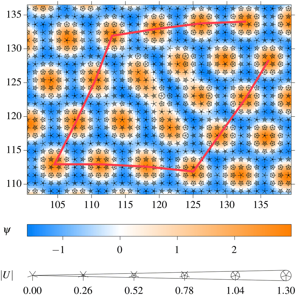
The different free energy levels correspond to periodic approximants of different sizes. Some of them do not fit well into the simulation box. In these cases, they are combined with filler structures, which likely can be viewed as smaller approximants in turn. The smaller the approximant's asymmetric unit, the higher is its free energy (see Fig. 7 for some examples).
 | ||
| Fig. 7 The columns (a) through (d) show typical configurations corresponding to the free energies labeled in Fig. 6. The top row displays the full density-like fields, with the orientation fields omitted. The insets in the top row show the absolute magnitudes of the Fourier transform of the respective density fields. The bottom row shows zoomed-in sections of the respective configurations, where the density-like field and orientation field are visualized as seen in Fig. 3. | ||
A mode analysis36,37 reveals that the dislocations, which had initially been present, usually annihilate during the minimization. So, in contrast to periodic structures, free energy changes are not caused by dislocations. This holds for all the free energy levels. The approximants seem to contain phasonic flips as the structures differ from the initial quasicrystalline patterns. The phasonic flips cause phasonic strain that probably causes the different free energy levels. This is similar to the situation in ref. 23 where two quasicrystals merge by relaxing the possible defects by phasonic flips but at the cost of exciting phasonic strain.
Although our minimization scheme is not a dynamical simulation, the process of annihilation observed during the minimization steps looks like what one would expect from a dynamical simulation: dislocations of opposing Burgers vectors approach each other and then recombine. The approach is facilitated by the local phasonic rearrangements. In very rare cases, we observe that dislocation pairs are formed and do not annihilate or move anymore.
Conclusions
We have studied grain boundaries in a system with preferred binding angles with a phase field crystal approach. To be specific, we have explored the grain boundaries in periodic crystals composed of particles with 5-fold rotational symmetry, and in addition, for comparison for particles with 2-fold symmetry and for isotropic particles. Furthermore, we have also studied dodecagonal quasicrystals obtained from particles with 6-fold rotational symmetry.We have found that the increase in free energy due to grain boundaries is slightly less pronounced for particles with 5-fold symmetry than for isotropic particles. Furthermore, for particles with 5-fold rotational symmetry, we observe a very strong orientational field at the position of the particles that have only five nearest neighbors. The strong orientation might be the reason for the less pronounced increase of the free energy.
However, we have not observed any preferred angles between the crystals in contact due to a preferred binding angle. To be specific, except for a small overall decrease, the free energy as a function of the relative angle between the crystals does not significantly change if particles with n = 5 instead of particles with isotropic symmetry (n = ∞) are considered.
If the preferred binding angles are used to stabilize a quasicrystal, we find a completely different behavior at the grain boundaries. The phasonic degrees of freedom are used to move the dislocations such that they can recombine with opposite dislocations from another grain boundary. As a result, one finds patterns with motives of quasicrystals but no dislocation at all. We argue that the situation is similar to that in ref. 23 and 24 where the number of defects was reduced due to phasonic rearrangements. However, here we even observe a more extreme behavior, as usually all dislocations disappear and the resulting pattern is distorted a lot which corresponds to a large phasonic strain. It seems that even local phasonic rearrangements can be easily excited in our model allowing an efficient way to repair defects.
As already pointed out in ref. 4, an important advantage of our approach is that the orientation field is treated separately from the local density field. Therefore, the strength of the orientation field at a grain boundary might differ from the strength of the orientation close to a particle in bulk. Furthermore, the effect of phasonic rearrangements can be studied with our model. As a consequence, our mean field approach is suitable to study and understand the behavior of particles with preferred binding angles close to grain boundaries.
Data availability
The data of Fig. 5 and 6 are available at OSF at https://doi.org/10.17605/OSF.IO/MRKNU.Author contributions
Conceptualization, methodology, validation, and writing of the original draft and reviewed article were carried out by both authors, RFBW and MS. Data curation, formal analysis, investigation, software development, and visualization were carried out by RFBW. Funding acquisition and supervision were performed by MS.Conflicts of interest
There are no conflicts to declare.Acknowledgements
Our work was funded by the Deutsche Forschungsgemeinschaft (DFG, German Research Foundation) under projects 374790102 and 541211648.Notes and references
- S. Glotzer and M. Solomon, Nat. Mater., 2007, 6, 557 CrossRef PubMed.
- E. Bianchi, R. Blaak and C. N. Likos, Phys. Chem. Chem. Phys., 2011, 13, 6397–6410 RSC.
- A. B. Pawar and I. Kretzschmar, Macromol. Rapid Commun., 2010, 31, 150–168 CrossRef CAS PubMed.
- R. F. B. Weigel and M. Schmiedeberg, Modell. Simul. Mater. Sci. Eng., 2022, 30, 074003 CrossRef.
- K. R. Elder, M. Katakowski, M. Haataja and M. Grant, Phys. Rev. Lett., 2002, 88, 245701 CrossRef CAS PubMed.
- K. R. Elder and M. Grant, Phys. Rev. E, 2004, 70, 051605 CrossRef CAS PubMed.
- J. Swift and P. Hohenberg, Phys. Rev. A: At., Mol., Opt. Phys., 1977, 15, 319 CrossRef.
- M. Cross and H. Greenside, Pattern Formation and Dynamics in Nonequilibrium Systems, Cambridge University Press, 2009 Search PubMed.
- S. van Teeffelen, R. Backofen, A. Voigt and H. Lowen, Phys. Rev. E, 2009, 79, 051404 CrossRef PubMed.
- K. R. Elder, N. Provatas, J. Berry, P. Stefanovic and M. Grant, Phys. Rev. B: Condens. Matter Mater. Phys., 2007, 75, 064107 CrossRef.
- R. Lifshitz and D. M. Petrich, Phys. Rev. Lett., 1997, 79, 1261 CrossRef CAS.
- K. Barkan, H. Diamant and R. Lifshitz, Phys. Rev. B: Condens. Matter Mater. Phys., 2011, 83, 172201 CrossRef.
- D. Shechtman, I. Blech, D. Gratias and J. W. Cahn, Phys. Rev. Lett., 1984, 53, 1951–1953 CrossRef CAS.
- X. Zeng, G. Ungar, Y. Liu, V. Percec, A. E. Dulcey and J. K. Hobbs, Nature, 2004, 428, 157–160 CrossRef CAS PubMed.
- X. Zeng, Curr. Opin. Colloid Interface Sci., 2005, 9, 384–389 CrossRef CAS.
- A. Takano, W. Kawashima, A. Noro, Y. Isono, N. Tanaka, T. Dotera and Y. Matsushita, J. Polym. Sci., Part B: Polym. Phys., 2005, 43, 2427–2432 CrossRef CAS.
- K. Hayashida, T. Dotera, A. Takano and Y. Matsushita, Phys. Rev. Lett., 2007, 98, 195502 CrossRef PubMed.
- S. Fischer, A. Exner, K. Zielske, J. Perlich, S. Deloudi, W. Steurer, P. Lindner and S. Forster, Proc. Natl. Acad. Sci. U. S. A., 2011, 108, 1810–1814 CrossRef CAS PubMed.
- J. E. S. Socolar, T. C. Lubensky and P. J. Steinhardt, Phys. Rev. B: Condens. Matter Mater. Phys., 1986, 34, 3345–3360 CrossRef PubMed.
- J. A. Kromer, M. Schmiedeberg, J. Roth and H. Stark, Phys. Rev. Lett., 2012, 108, 218301 CrossRef PubMed.
- C. V. Achim, M. Schmiedeberg and H. Lowen, Phys. Rev. Lett., 2014, 112, 255501 CrossRef CAS PubMed.
- K. Nagao, T. Inuzuka, K. Nishimoto and K. Edagawa, Phys. Rev. Lett., 2015, 115, 075501 CrossRef PubMed.
- M. Schmiedeberg, C. V. Achim, J. Hielscher, S. C. Kapfer and H. Lowen, Phys. Rev. E, 2017, 96, 012602 CrossRef CAS PubMed.
- I. Han, K. L. Wang, A. T. Cadotte, Z. Xi, H. Parsamehr, X. Xiao, S. C. Glotzer and A. J. Shahani, Nat. Commun., 2021, 12, 5790 CrossRef CAS PubMed.
- M. N. van der Linden, J. P. K. Doye and A. A. Louis, J. Chem. Phys., 2012, 136, 054904 CrossRef PubMed.
- A. Reinhardt, F. Romano and J. P. K. Doye, Phys. Rev. Lett., 2013, 110, 255503 CrossRef PubMed.
- A. Gemeinhardt, M. Martinsons and M. Schmiedeberg, Eur. Phys. J. E:Soft Matter Biol. Phys., 2018, 41, 1 CrossRef PubMed.
- J. P. K. Doye, A. A. Louis, I.-C. Lin, L. R. Allen, E. G. Noya, A. W. Wilber, H. C. Kok and R. Lyus, Phys. Chem. Chem. Phys., 2007, 9, 2197 RSC.
- E. G. Noya, C. Vega, J. P. K. Doye and A. A. Louis, J. Chem. Phys., 2007, 127, 054501 CrossRef CAS PubMed.
- E. G. Noya, C. Vega, J. P. K. Doye and A. A. Louis, J. Chem. Phys., 2010, 132, 234511 CrossRef PubMed.
- C. V. Achim, R. Wittkowski and H. Lowen, Phys. Rev. E, 2011, 83, 061712 CrossRef PubMed.
- R. Wittkowski, H. Lowen and H. R. Brand, Phys. Rev. E, 2011, 83, 061706 CrossRef PubMed.
- H. Lowen, J. Phys.: Condens. Matter, 2010, 22, 364105 CrossRef PubMed.
- K. Barkan, M. Engel and R. Lifshitz, Phys. Rev. Lett., 2014, 113, 098304 CrossRef CAS PubMed.
- J. A. Nelder and R. Mead, Comput. J., 1965, 7, 308–313 CrossRef.
- W. Yang, R. Wang, M. Feuerbacher, P. Schall and K. Urban, Philos. Mag. Lett., 2000, 80, 281–288 CrossRef CAS.
- L. Korkidi, K. Barkan and R. Lifshitz, Aperiodic Crystals, Dordrecht, 2013, pp. 117–124 Search PubMed.
| This journal is © The Royal Society of Chemistry 2025 |