
 Open Access Article
 This Open Access Article is licensed under a Creative Commons Attribution-Non Commercial 3.0 Unported Licence
Size-selective sorting of kaolinite micro/nanoflakes via microfluidic filtration for wound hemostasis†
Guangyao
Li‡
a,
Liang
Wan‡
b,
Ying
Chen
 *a,
Xuming
Zhang
*b,
Aidong
Tang
ac and
Huaming
Yang
*ad
*a,
Xuming
Zhang
*b,
Aidong
Tang
ac and
Huaming
Yang
*ad
aEngineering Research Center of Nano-Geomaterials of Ministry of Education, Laboratory of Advanced Mineral Materials, Faculty of Materials Science and Chemistry, China University of Geosciences, Wuhan 430074, China. E-mail: chenying2021@cug.edu.cn; hm.yang@cug.edu.cn
bDepartment of Applied Physics & Research Centre for Resources Engineering Towards Carbon Neutrality (RCRE), The Hong Kong Polytechnic University, Hong Kong, 999077, China. E-mail: xuming.zhang@polyu.edu.hk
cCollege of Chemistry and Chemical Engineering, Central South University, Changsha 410083, China
dHunan Key Laboratory of Mineral Materials and Application, School of Minerals Processing and Bioengineering, Central South University, Changsha 410083, China
First published on 6th June 2025
Abstract
Kaolinite, a natural micro/nano clay material, exhibits remarkable effect on wound hemostasis, yet its efficacy is critically limited by heterogeneous particle sizes. Therefore, sorting based on size differences is essential to improve its performance. However, kaolinite with a layer structure presents challenges in sorting compared to spherical or elliptical materials, and the size distribution ranges continuously from nanometers to micrometers, which poses significant challenges for precise sorting. Hence, we developed a dual-layer microfluidic filtration chip, to enable high-throughput sorting of kaolinite micro/nanoflakes (size from 1.582 to 0.377 μm). The dual-layer filter membrane structure with graded pore sizes enabled selective sorting of kaolinite particles within a specific size range, and the co-flow fluid arrangement was employed to alleviate membrane clogging. The hemostatic properties of kaolinite particles with different sizes were evaluated through in vivo and in vitro experiments, revealing the significant size-dependent effects of kaolinite on wound hemostasis. The mechanism of different sizes of kaolinite in the process of coagulation, especially the effect on platelet activation and coagulation factor activation, provided a theoretical basis for optimizing kaolinite-based hemostatic materials. This work established a scalable microfluidic strategy for precise sorting of sheet nanomaterials and improved the translational potential of kaolinite in emergency wound hemostasis.
Introduction
Biomedicine is crucial to human health and has long been a focal point of international research.1 Within this domain, hemostatic materials are indispensable for controlling bleeding and saving lives, especially in emergency situations such as battlefields, traffic accidents, and other traumatic injuries.2 Natural mineral materials, including zeolite, montmorillonite, and kaolinite, possess well-developed microporous structures, large specific surface areas, and exceptional adsorption capabilities. These intrinsic properties facilitate the rapid absorption of wound exudates and enhance blood coagulation processes, leading to effective hemostatic control. Furthermore, their widespread natural occurrence and cost-effectiveness make them particularly suitable for extensive practical applications.3–5 Although zeolite and montmorillonite show significant potential for hemostatic applications, their clinical implementation is limited by several critical factors that require careful consideration.6–9 In particular, zeolite's macroporous structure may cause excessive platelet activation and thrombosis risks,10 while montmorillonite's strong adsorption can form occlusive barriers that delay hemostasis and its slow biodegradation may impair wound healing;11 these limitations restrict their clinical translation despite their inherent potential.Kaolinite, as a natural clay mineral with the molecular formula Al2Si2O5(OH)4·nH2O (n = 0 or 2), has emerged as a superior candidate for next-generation hemostatic materials, distinguished by its exceptional safety profile and therapeutic efficacy.3,12 The unique microporous architecture and optimal adsorption characteristics of kaolinite facilitate efficient wound exudate management and promote physiological platelet aggregation and activation, thereby establishing an ideal microenvironment to accelerate coagulation cascade initiation.13 Unlike other mineral-based hemostats, kaolinite demonstrates remarkable biocompatibility and negligible immunogenicity, which significantly mitigate inflammatory responses and preserve tissue integrity during the healing process.14 Furthermore, kaolinite exhibits rapid clearance kinetics from the wound microenvironment, mitigating the potential for foreign body reactions while creating favorable conditions for physiological wound healing progression. Despite its inherent advantages, natural kaolinite is fundamentally constrained by its morphological characteristics, particularly its large particle dimensions and heterogeneous size distribution, which critically undermine its hemostatic performance.15,16 Specifically, the larger particle size hinders the rapid penetration of kaolinite particles to the depths of the wound, thereby restricting their full contact with blood. Moreover, the non-uniform adsorption layer formed by unevenly sized particles on the wound surface fails to effectively facilitate the uniform aggregation and activation of platelets, consequently compromising the speed and quality of blood coagulation.17–19 This morphological irregularity thus leads to inconsistent thrombin generation and fibrin network formation, ultimately manifesting as compromised coagulation kinetics and suboptimal clot stability.20 These limitations result in the suboptimal hemostatic efficiency of natural kaolinite, making it inadequate to meet the stringent demands of emergency hemostasis.
Currently, the size control and sorting of kaolinite have attracted widespread attention and have been the subject of extensive research. In terms of size control, common methods include mechanical grinding,21 chemical modification,22 heat treatment,23 solvothermal methods,24 ultrasonic treatment,25 and electrostatic deposition.26 For the sorting and collection of kaolinite, a variety of technical means are also available, such as sieving, sedimentation, ultrasonic dispersion and classification, air classification, magnetic separation, etc.27,28 In recent studies, separation techniques for layered materials have achieved significant progress. For example, Zhao et al. reviewed the latest advances in selective separation and precise control of two-dimensional (2D) layered membranes, discussing the effects of size exclusion, charge properties, and chemical affinity on the accurate separation of 2D membranes, along with a summary and analysis of existing research on their precise control and selective separation processes.29 Additionally, Zhang et al. enhanced the separation accuracy by hybridizing materials of different dimensions to regulate the structure and performance of layered membranes.30 However, current techniques for kaolinite size sorting are plagued by several critical limitations. These methods mainly rely on time-consuming multi-step processes under batch conditions, which are inherently inefficient for particle sorting. Although effective for coarse particles (>75 μm), they lack extensibility and accuracy in micro/nano-scale applications. Consequently, the development of a precise, scalable, and environmentally sustainable approach for kaolinite size sorting remains an unresolved scientific and technological challenge.
Microfluidics, characterized by its microscale operation, high-precision control and high-throughput processing, has shown significant advantages in material screening.31–33 For example, microfluidic filtration technology has important applications in cell sorting. Kim et al. utilized microfluidic filtration technology to achieve the separation of white blood cells from whole blood with a purity greater than 90%,34 and Qiu et al. filtered large tissue fragments and collected single cells.35 Therefore, microfluidic filtration chips are expected to enable the sorting of kaolinite particles at micro/nano-scale sizes. In this context, microfluidic sorting technology provided inspiration for the separation of layered materials. However, current microfluidic sorting techniques (e.g., deterministic lateral displacement (DLD), inertial microfluidics), while effective for spherical particles, faced limitations when processing layered materials due to their geometric characteristics (high aspect ratio, continuous size distribution). For instance, Liu et al. attempted to use inertial flow to separate two fine mineral particles, but the purity of separation needed to be improved.36 Therefore, there is an urgent need to develop novel microfluidic strategies for the sorting of kaolinite particles to address challenges related to clogging, throughput, and resolution.
In this work, a unique microfluidic filter was designed and achieved precise sorting of kaolinite micro/nanoflakes after pre-treatment by intercalation and ultrasonic exfoliation. The device integrated traditional filtration and tangential flow filtration modes, utilizing co-flow to alleviate membrane clogging, which was expected to enable the sorting and collection of micro/nano-sized kaolinite from a mixture of particles with a continuous size distribution. Meanwhile, the hemostatic performance of kaolinite particles with varying sizes was systematically evaluated through both in vivo and in vitro experiments, uncovering the significant size-dependent effects of kaolinite on wound hemostasis. This study provided an effective and controllable method for high-precision screening of micro/nano-scale kaolinite, which not only improved the hemostatic performance, but also enhanced the practicality and social value of microfluidics.
Results and discussion
Screening of kaolinite particles based on microfluidics
The microfluidic filtration device was developed and used for size-based sorting of kaolinite particles after pre-treatment (Fig. 1a). The microfluidic filtration chip was constructed using a multilayer assembly approach, and the cross-sectional details are provided in Fig. 1b. The microfluidic filtration chip had a total of 7 layers, which were the upper and lower sealing layers. In the middle, there were 3 layers of laser-processed polymethyl methacrylate (PMMA) plates as the upper, middle and lower flow channel layers. The flow channel layers were separated by elastomeric silicone gaskets and polycarbonate filter membranes, respectively. The polycarbonate filter membrane had the advantage of being low in price and could be cut at will. The entire chip was finally fixed by a screw. Compared with fixing glue, this method was easy to disassemble and facilitated replacement of the filter membrane at any time. The microfluidic chip (7.5 cm × 4.5 cm × 1 cm) featured a serpentine channel design (PMMA/gasket thickness: 1 mm, channel width: 1 mm) to prolong particle residence time near the filtration membrane. This device integrated a filtration mechanism combining conventional filtration with tangential flow filtration (TFF) technology (Fig. 1c), which offered the following advantages for the separation of layered materials: (1) reduced clogging; layered materials tended to form dense stacks or align parallel to the membrane surface in conventional filtration, causing rapid clogging. TFF introduced tangential shear forces that disrupted this stacking. (2) Size selectivity; the tangential flow enhanced the separation of layer kaolinite from thicker aggregates by exerting differential shear forces, in that thinner flakes remained suspended in the flow while thicker particles were retained, which was critical for obtaining monodisperse 2D materials.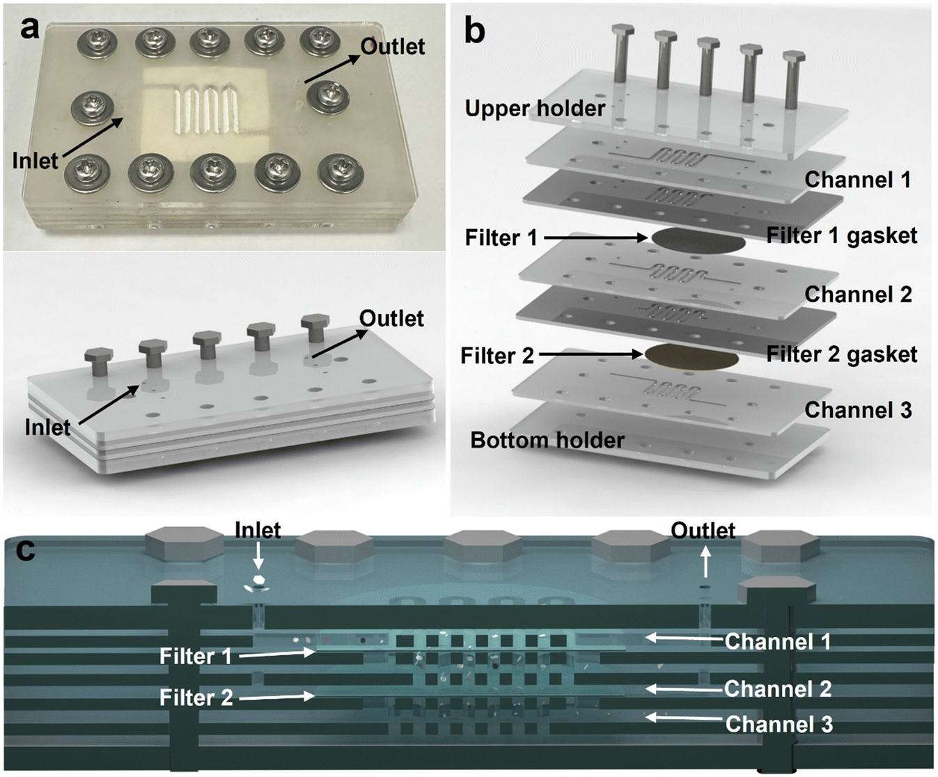 | ||
| Fig. 1 (a) Physical prototype (up) and model diagram (down) of the microfluidic filter device. (b) Internal structural details and (c) cross-sectional details including three channel layers, two gasket layers with filters, and two layers to seal the top and bottom of the device. | ||
The schematic illustration and physical image of the microfluidic filtration device for the screening of kaolinite micro/nano-flakes are illustrated in Fig. 2a and S1.† The system integrated customizable polycarbonate membranes and utilized four precision pumps: an injection pump (200 μL min−1) for sample introduction (defined as Kaol-0), and three withdrawal pumps (outlet 1: 40 μL min−1 for filter 1 particle removal; outlets 2 and 3: 40 μL min−1 and 120 μL min−1 respectively) enabling size-based separation through sequential filtration. The sample was directed through microfluidic channels to be in contact with membrane filter 1 (0.8 μm), which featured larger pore dimensions. Particles permeating through this membrane subsequently entered the intermediate channel where they encountered the membrane filter 2 (0.45 μm) with significantly reduced pore sizes. Particulate matter smaller than the membrane's pore specifications migrated to the bottom channel and ultimately exited through the outlet port. A proportion of the sample could alternatively be guided along the membrane surfaces and discharged through the co-flow outlet. Three dedicated outlet pumps (defined as outlets 1, 2 and 3) were strategically positioned to withdraw the kaolinite suspension from the microfluidic chip, thereby precisely regulating the hydrodynamic pathways and flow distribution within the system.
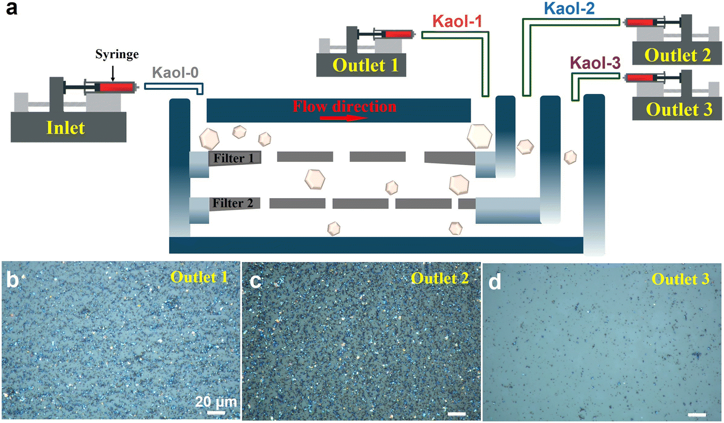 | ||
| Fig. 2 (a) Schematic illustration of the microfluidic filtration device for the screening of micro/nano-scale kaolinite. (b–d) Optical microscope views of the collection at outlets 1, 2, and 3 respectively. | ||
The morphologies of kaolinite at different outlets (1, 2 and 3) were observed by optical microscopy (Fig. 2b–d), and the results showed that kaolinite particles with different sizes were collected at outlets 1, 2 and 3, respectively, indicating that the dual-layer microfluidic filtration chip effectively sorted according to particle size. Compared to the unused membrane, the membrane surface exhibited severe clogging when kaolinite was sorted using a direct filtration method (Fig. S2a and b†). However, the dual-layer microfluidic filtration chip designed in this work, which employed the co-flow fluid arrangement, exhibited a uniform membrane surface after kaolinite sorting, effectively alleviating the clogging issue (Fig. S2c†). This design not only improved the efficiency of material sorting but also extended the service life of the membrane, thereby demonstrating significant advantages in practical applications.
Structural characteristics of kaolinite with different sizes
The particle size distribution of kaolinites screened from outlets 1, 2 and 3 were measured by Dynamic Light Scattering (DLS), respectively. By contrast, the size distribution range of unscreened kaolinite (Kaol-0) was wide, and the median diameter (D50) reached 2.7 ± 0.537 μm, indicating that the size of Kaol-0 was large and uneven (Fig. S3†). After two-step intercalation, ultrasonic exfoliation intercalation and chip screening, the overall particle size distribution of kaolinite shifted to lower particle size and the peak shape was narrower, indicating that the microfluidic chips realized the sorting and collection of kaolinite of different sizes, in which the median particle sizes (D50) of Kaol-1, Kaol-2 and Kaol-3 were 1.582 ± 0.127, 0.617 ± 0.033 and 0.377 ± 0.009 μm, respectively (Fig. 3a and b). The morphology of kaolinite was characterized by scanning electron microscopy (SEM) and transmission electron microscopy (TEM), respectively. The SEM results indicated that the kaolinite maintained a lamellar structure before and after screening (Fig. 3c and S4†). It was clearly observed that the lamellar structure of Kaol-0 was not uniform in size. After two-step intercalation, ultrasonic exfoliation intercalation and chip screening, the morphology of lamellar kaolinite was more regular, and the average diameters of Kaol-1, 2 and 3 were 1.250 ± 0.035, 0.575 ± 0.012 and 0.328 ± 0.004 μm, respectively, which was basically consistent with the particle size distribution results. The lamellar hexagonal morphology of kaolinite was obviously observed by TEM (Fig. S5†). The stack of Kaol-0 was tighter, and the edges were regular and neat. However, with the decrease of particle size, the lamellar kaolinite was disorganized, and the exposed edges were passivated and damaged. Since the input kaolinite particles exhibited continuous size distribution, the sorted kaolinite collected from each outlet possessed a specific size range. The purity of kaolinite collected from outlets 1, 2, and 3 reached 99.5%, 98.5%, and 100%, respectively. After sorting, the recovery rate of kaolinite achieved 83.4%, 60.1%, and 56.1%, respectively. These results demonstrated the performance of the microfluidic filtration chip in fractionating kaolinite with high size selectivity.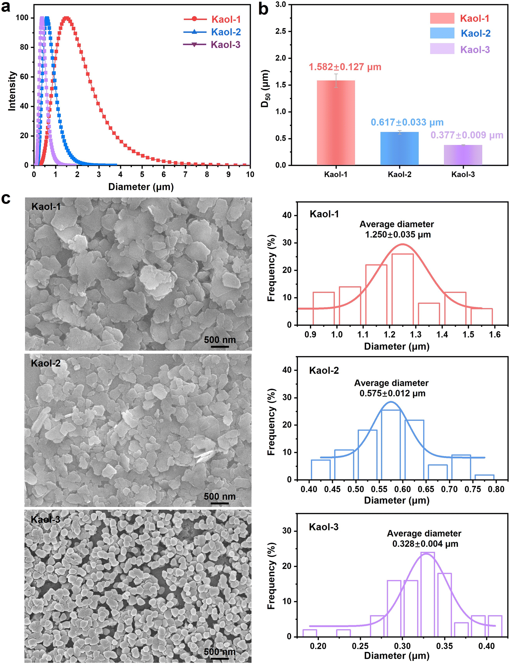 | ||
| Fig. 3 (a) Particle size distribution and (b) median particle sizes (D50). (c) SEM images and particle size statistical histograms. | ||
The phase structure of kaolinite with different sizes was characterized by X-ray diffraction (XRD), as shown in Fig. 4a. The characteristic diffraction peaks of Kaol-0 at (001) and (002) were sharp and strong, indicating that the crystalline structure of unscreened kaolinite was regular and complete. With the decrease of the size, especially in Kaol-3, the diffraction peak intensity corresponding to the (001) crystal surface of kaolinite decreased gradually, and the diffraction peak widened obviously, indicating that the layer structure of kaolinite was destroyed, and the order degree was reduced. However, the position of the (001) and (002) diffraction peaks did not shift significantly, indicating that the process of ultrasonic exfoliation only changed the stacking degree of kaolinite in the c-axis, and did not damage the a- and b-axes lamellar structure of kaolinite.
 | ||
| Fig. 4 (a) XRD patterns, (b) nitrogen adsorption/desorption isotherms, (c) BJH pore size distribution and (d) zeta potentials (pH = 6.8) of Kaol-0, 1, 2 and 3, respectively. | ||
Brunauer–Emmett–Teller (BET) analysis was performed to compare the difference of the specific surface area and pore structure of kaolinite with different sizes. As shown in Fig. 4b, Kaol-0, 1, 2 and 3 had similar N2 adsorption and desorption isotherms, all belonging to type VI adsorption isotherms. The specific surface area and pore structure parameters are exhibited in Fig. 4c and Table S1.† The specific surface area and pore structure of Kaol-0 were generally low. With the decrease of kaolinite particle size, the specific surface area and pore structure of kaolinite was expanded, among which Kaol-3 reached a surface area of 34.213 m2 g−1, a pore size of 24.838 nm, and a pore volume of 0.242 cm3 g−1, respectively. These results were due to the loose accumulation caused by the reduction of kaolinite size, resulting in the increase of mesopores and pore size of kaolinite.
In the process of hemostasis, the electronegativity of hemostatic materials is the key to affecting the hemostatic effect. The aluminosilicate layered structure in kaolinite is composed of silicon–oxygen tetrahedral layers (Si–O) and aluminum–oxygen octahedral layers (Al–O). Accompanied by the isomorphic substitution of Al for Si, it led to the generation of permanent negative charges on the crystal planes of kaolinite. Simultaneously, the surface of kaolinite contains abundant active groups such as Al–O, Si–O, and Al–OH, which readily undergo deprotonation in aqueous solutions, thereby further increasing the surface negativity. As the particle size of kaolinite decreases, its specific surface area increases significantly, which means that per unit mass of kaolinite possesses more surface active sites capable of adsorbing additional negative charges, consequently enhancing its electronegativity. Furthermore, the reduced particle size leads to more concentrated charge distribution on the particle surfaces, which further amplifies the overall electronegativity. The zeta potential (using deionized water, pH = 6.8) analysis results indicated that kaolinite always maintained obvious electronegativity with the decrease of size, and the smaller the kaolinite particles, the stronger the electronegativity (Fig. 4d). The negative charge is beneficial to the facilitation of the self-activation pathway to trigger the intrinsic clotting cascade, thus promoting hemostasis. Fig. S6† exhibits the zeta potential of kaolinite under simulated physiological conditions (using PBS buffer, pH 7.4). These results indicated that the electronegativity of kaolinite increased further due to enhanced deprotonation at higher pH, leading to higher negative charge density.
Hemostatic performance evaluation
The in vitro hemostatic effect of kaolinite was evaluated through a dynamic coagulation experiment, and the experimental process and details are shown in Fig. 5a and S7.† Fig. S7† illustrates the three key steps of the dynamic coagulation assay: (I) setup of blank/control/experimental groups, (II) co-incubation of blood with samples, and (III) dissolution of uncoagulated red blood cells to quantify hemostatic efficacy. Specifically, 10 mg of sample was mixed with 100 μL rabbit blood, followed by the addition of 10 μL 0.2 M CaCl2 to initiate coagulation. After 10 min of incubation at 37 °C, the reaction was terminated with deionized water, and the absorbance at 540 nm was measured post-centrifugation. The hemostatic effect of kaolinite with different sizes was evaluated by measuring the absorbance of hemoglobin released from unbound red blood cells. As shown in Fig. 5a inset, the absorbance of kaolinite samples was significantly reduced, indicating that the coagulation effect of kaolinite was obvious. Moreover, as the size of kaolinite decreased, the absorbance decreased further, which proved that the hemostatic performance of kaolinite was dependent on the size. | ||
| Fig. 5 (a) In vitro hemostatic effect of samples evaluated through the dynamic coagulation experiment. (b) Blood clotting index (BCI) and (c) hemostasis time of Kaol-0, 1, 2 and 3, respectively. (d) SEM images of interfacial interactions between samples and red blood cells (scale bar: 2 μm). (e) Schematic diagram of the mouse liver hemorrhage model. (f) Blood loss and (g) hemostasis time of different groups in the mouse liver hemorrhage model. | ||
The blood clotting index (BCI) further reflected the clotting ability of the samples to the blood, in which the higher the BCI value, the slower the clotting rate. As shown in Fig. 5b, the BCI value of Kaol-3 reached 24.69%, further confirming the hemostatic advantage in small size kaolinite. The whole blood clotting time of kaolinite is exhibited in Fig. 5c, which was nearly half shorter than that of the control group. The clotting time of kaolinite was shortened by more than 50%, among which Kaol-3 could reach less than 50 s.
By observing the adhesion of red blood cells on the surface of materials, the hemostatic performance of the materials can be evaluated. Under the view of SEM, the red blood cells exhibited a typical biconcave disc shape (Fig. S8†). Fig. S9† showed the interaction between kaolinite and red blood cells, where pronounced aggregation and stacking between kaolinite particles and red blood cells were observed, which was attributed to the interplay between the surface properties of kaolinite and the red blood cell membrane. Under the well-dispersed conditions, kaolinite particles were found to adhere tightly to the red blood cell surface (Fig. 5d). Additionally, variations in kaolinite particle size led to differences in red blood cell surface coverage and distribution. The morphology of the adherent red blood cells indicated that smaller kaolinite particles were more conducive to adhesion with red blood cells. The layer structure and mesoporous structure of kaolinite could absorb blood plasma, reduce blood fluidity, and facilitate the adhesion and aggregation of red blood cells on its surface. This process promoted the activation of the intrinsic coagulation cascade, thereby achieving hemostasis, which was supported by extensive literature reports.13,37
Subsequently, the mouse liver hemorrhage model was evaluated with the in vivo hemostatic tests (Fig. 5e and S10†). As shown in Fig. 5f, with the size of kaolinite decreasing, the liver blood loss in mice was reduced, with the blood loss potentially dropping to as low as 70 mg (Kaol-3). At the same time, the hemostasis time was also significantly reduced (Fig. 5g), with the hemostasis time between Kaol-0 and Kaol-3 differing by nearly twice, and that in Kaol-3 was only 72 s.
The coagulation function was evaluated by incubating kaolinite with platelet-poor plasma (PPP) suspension and measuring key parameters including activated partial thromboplastin time (APTT), prothrombin time (PT), thrombin time (TT), and fibrinogen (Fib) levels. These parameters respectively reflect the intrinsic and extrinsic coagulation pathways, fibrinogen conversion capacity, and plasma fibrinogen concentration, thereby providing valuable insights for clinical diagnosis and therapeutic interventions. As shown in Fig. 6a, all four measured parameters including APTT, PT, TT and Fib remain within their respective normal reference ranges. A significant reduction of PT in Kaol-1, 2 and 3 groups respectively was observed compared to the blank group, demonstrating that kaolinite exhibited a notable activation effect on the extrinsic coagulation pathway. The lack of significant changes in APTT and TT indicated that kaolinite primarily activated the extrinsic coagulation pathway, with minimal impact on intrinsic pathways. Furthermore, the decreased Fib level indicated that kaolinite had a certain adsorption effect on plasma proteins.
 | ||
| Fig. 6 (a) Results of the clinical standard coagulation test. (b) The adherent platelets stained with FITC-phalloidin. (c) FCM analysis diagrams of platelet activation (CD61 + CD62p) of Kaol-0, 1, 2 and 3, respectively. | ||
To investigate the interaction between kaolinite and platelets, kaolinite was co-incubated with platelet-rich plasma (PRP), simulating its effects on platelet activation and aggregation (Fig. 6b). Following FITC-phalloidin fluorescent staining, adherent platelets were specifically labeled, exhibiting distinct bright green fluorescence. The fluorescence intensity correlated positively with the number of adherent platelets, while the negative control group displayed no significant fluorescence signal. The presence of abundant negative charges and Si–OH functional groups on the kaolinite surface was found to promote robust platelet adhesion. Notably, a reduction in kaolinite particle size resulted in enhanced fluorescence intensity, demonstrating that kaolinite with a higher specific surface area exhibits superior platelet interaction capabilities.
The activation status of platelets was quantitatively evaluated using fluorescently labeled antibodies that specifically target granular membrane proteins (such as CD62P) expressed on the surface of activated platelets. Flow cytometry (FCM) analysis was performed to determine the platelet activation levels following kaolinite incubation (Fig. 6c). In the histogram of CD62P PE-A, with the particle size of kaolinite decreased and uniformity improved, the proportion of activated platelets gradually increased, indicating the distinct size-dependent relationship in kaolinite-induced platelet activation. In the scatter plot of CD62P PE-A/CD61 FITC-A, the platelet activation ratio in Kaol-3 reached 6.36%, which was three times higher than that of the blank group (1.94%) and nearly twice that of Kaol-0 (3.38%) and Kaol-1 (3.60%), further confirming the hemostatic application advantages and size-dependent characteristics of kaolinite.
Kaolinite effectively adsorbs blood cells and platelets through its unique layered structure and abundant surface hydroxyl groups, thereby promoting blood coagulation. Moreover, the smaller the size of kaolinite, the larger the specific surface area, and the greater the contact area with blood, which was more conducive to promoting hemostasis. The flaky structure and mesoporous structure of kaolinite could adsorb blood, reducing its fluidity, allowing red blood cells to adhere and aggregate on the surface, promoting the auto-activation to trigger the intrinsic coagulation cascade, thereby achieving hemostatic function. In conclusion, the synergistic effect between the size, morphology, mesoporous structure and surface negative charge of kaolinite is the key to its excellent hemostatic performance.
Conclusion
In this work, the dual-layer microfluidic filtration chip achieved high-throughput sorting of kaolinite micro/nanoflakes. This dual-layer filtration membrane structure with graded pore sizes allowed selective sorting of kaolinite particles within a specific size range, and the co-flow fluid arrangement effectively mitigated membrane clogging, enhancing the overall efficiency and reliability of the filtration process. The kaolinite particles with different sizes were further selected for subsequent structural characterization and hemostatic performance studies, and the experiments showed that small-size particles (Kaol-3) exhibited optimal hemostatic properties, which was attributed to its unique physical and chemical properties, including the abundant hydroxyl groups, two-dimensional layered structure, large specific surface area, and negative surface charge of kaolinite. Moreover, mechanism analysis revealed that the smaller the size of the kaolinite, the more pronounced the size effect, which was more conducive to the contact with blood, promoting platelet aggregation and thus enhancing hemostasis. This work not only provided a microfluidic technical solution for the high-throughput sorting of natural mineral materials but also laid a theoretical and technical foundation for the development of efficient hemostatic dressings.Experimental section
Materials and reagents
Kaolinite (Pharmaceutical grade) was purchased from Shanghai Aladdin Biochemical Technology Co., LTD (Shanghai, China). CaCl2, dimethyl sulfoxide (DMSO) and urea were procured from Sinopharm Chemical Reagent Co. Ltd (Shanghai, China). All reagents were used without further purification. Deionized water (DI, 18.2 Ω cm−1) was used throughout the experiments. The membranes used in this work were purchased from MemberSpace (USA), and the core parameters were exhibited in Table S2.†Kaolinite pre-treatment
The raw materials of kaolinite were firstly broken down before the screening, which was realized by two-step intercalation and ultrasonic exfoliation. Typically, a 10 g kaolinite was added to the mixed solution of 90.0 mL DMSO and 10.0 mL DI water and stirred for 24 h at 60 °C. The suspension was centrifuged, and the precipitate was washed several times using deionized water, and the kaolinite complex intercalated by DMSO (Kaol-DMSO) was obtained. Then, 5 g Kaol-DMSO was added to the 50 mL saturated urea solution (13 mol L−1) and stirred for 24 h at 60 °C. The suspension was centrifuged, and the precipitate was washed several times using deionized water, and the kaolinite complex intercalated by urea (Kaol-Urea) was obtained. Finally, 2 g Kaol-Urea was dispersed in 200 mL deionized water and subjected to ultrasonic exfoliation for 5 h at 60 °C with a power of 1500 W.Characterization
X-ray diffraction (XRD) patterns were captured with a BRUKER D8 ADVANCE diffractometer, utilizing Cu Kα radiation at 40 kV/40 mA, scanning from 2θ of 5–80° at a rate of 5° min−1. The field-emission scanning electron microscopy (SEM) images were obtained from a Zeiss Supra 55 SEM. High-resolution transmission electron microscopy (HRTEM) images were obtained on a JEOL JEM-2010 transmission electron microscope. The Brunauer–Emmett–Teller (BET) surface area was collected using a TriStar II 3200. The surface area and porosity metrics were gauged using N2-adsorption–desorption isotherms and analyzed via the BJH method. The zeta potential was measured with a NanoBrook 90plus PALS analyzer. Contact angle determinations were made using a DataPhysics OCA-20.Dynamic coagulation effects
Firstly, weigh 10 mg samples and add them to 6-well plates and add 100 μL blood to each well, which was New Zealand white rabbits' blood and used in the following experiment referred to this type. Then, immediately add 10 μL 0.2 M CaCl2 to trigger coagulation. The 6-well plates were incubated in a water bath at 37 °C for 10 min. Then, add 10 mL of deionized water drop by drop to avoid damaging the blood clots, which was used to stop the coagulation reaction. After that, 5 mL of the liquid was then removed and centrifuged at 1000 rpm for 1 min. The supernatant of each group was collected and transferred to the 96-well plate, and the absorbance at 540 nm of the samples of each group was detected using an enzyme labeling instrument. The higher the absorbance of the supernatant, the more blood cells were dissolved, indicating poor hemostatic performance.Blood clotting index (BCI) is an important index used to evaluate the ability of blood to clot, which was calculated as follows:
| BCI (%) = As/Ab × 100 | (1) |
Whole blood clotting time
Weigh 10 mg samples and place them into a 1.5 mL centrifuge tube. Then, 100 μL of whole blood and 10 μL of CaCl2 (0.2 M) solution were added successively. Subsequently, the centrifuge tube was placed in a 37 °C water bath and then tilted every 5 s to observe the blood flow status. When the blood stopped flowing, it was recorded as the end time, and the time difference was taken as the coagulation time. The experiment was repeated three times.Clinical standard blood coagulation tests
The activated partial thromboplastin time (APTT), prothrombin time (PT), thrombin time (TT), and fibrinogen (FIB) tetrameter tests were commonly used to reflect the coagulation activity clinically. Here, 50 μL of various samples were taken and added into a 1.5 mL centrifuge tube (vortex mixing before adding), PPP 500 μL was taken with a pipette and added into the sample tube, and PRP was evenly mixed with the sample with a gun tip, and incubated at 37 °C with horizontal oscillation for 15 min. 0.5 mL PPP was added to 50 μL PBS as a blank control and incubated with horizontal oscillations at 37 °C for 15 min. Three parallel sets were set for both the sample group and the control group. After the incubation was completed, the sample was centrifuged at 2000g for 10 minutes, and the upper PPP sample was taken. The APTT, PT, TT and Fib indicators of PPP after incubation were detected by the fully automatic coagulation analyzer (STA R Max, Stago).Morphology of adherent red blood cells
Firstly, the fresh whole blood was centrifuged at 1500 rpm for 10 min to obtain the red blood cells, and a blood cell suspension was obtained by diluting blood cells using PBS at a ratio of 1![[thin space (1/6-em)]](https://www.rsc.org/images/entities/char_2009.gif) :10 before use. Then, 5 mg samples were soaked into 200 μL of diluted whole blood solution and incubated at 37 °C for 1 h. Finally, the non-adherent red blood cells were completely removed with PBS three times. Subsequently, the samples with aggregated red blood cells were fixed with 2.5% of glutaraldehyde for 2 h. The dehydrated samples were characterized by SEM.
:10 before use. Then, 5 mg samples were soaked into 200 μL of diluted whole blood solution and incubated at 37 °C for 1 h. Finally, the non-adherent red blood cells were completely removed with PBS three times. Subsequently, the samples with aggregated red blood cells were fixed with 2.5% of glutaraldehyde for 2 h. The dehydrated samples were characterized by SEM.
Platelet activation and aggregation analysis
The activated and aggregated platelets on the sample's surface were evaluated by FITC-phalloidin staining. Initially, 5 mg of the sample was incubated with 200 μL of platelet-rich plasma (PRP) at 37 °C for 1 h, then the materials were washed with PBS (pH = 7.4); platelet-poor plasma (PPP) with kaolinite served as the negative control. The platelets on the material were fixed with 4 vol% of paraformaldehydes for 20 min. After that, the samples were washed with PBS followed by adding 0.5 mL of 0.1% Triton X-100, and the Triton X-100 solution was washed away after 5 min using PBS three times again. Afterwards, 200 μL of 100 nmol L−1 FITC-phalloidin (Yeasen Biotechnology Co., Ltd., Shanghai, China) was applied for staining, and the culture plate was placed in the dark for 30 min at room temperature. Finally, it was washed with PBS 3 times and observed using an inverted fluorescence microscope.To quantify platelet activation, the fresh PRP was obtained for the flow cytometry (FCM) assay. A 10 μL volume of sample suspension (sample in PBS with a concentration of 10 mg mL−1) was mixed with 90 μL of PRP for 5 min. Next, 5 μL of the treated blood was stained with platelet-activation-dependent monoclonal antibodies (FITC anti-rat CD61 for platelet activation, PE anti-rat CD62p for activation identification purchased from BD Biosciences) and incubated at room temperature for 20 min, avoiding light. Finally, a flow cytometer was employed to analyze the data. Experiments were performed on three different blood samples.
In vivo hemostatic tests
All animal procedures were performed in accordance with the Guidelines for Care and Use of Laboratory Animals of “the National Institutes of Health (NIH) of the USA” and approved by the Animal Ethics Committee of “Hubei Provincial Center for Disease Control and Prevention Institutional Animal Care and Use Committee” (approval number: number 202529025). The hemostatic test of kaolinite was evaluated using the mouse liver hemorrhage model. Firstly, the mice were anesthetized, and the liver was exposed through an abdominal incision. After carefully removing the tissue fluid surrounding the liver, pre-weighed filter paper was placed further below the liver. Hepatic hemorrhage was induced with scissors and then different samples were immediately overlaid on the bleeding site. Data on blood loss and time to hemostasis were recorded throughout the hemostasis process.Data availability
This work is original and has not been published previously by any of the authors and/or is not under consideration for publication in another journal at the time of submission. It is agreed to the submission by all the authors. The data that support the findings of this study are available from the corresponding author upon reasonable request.Author contributions
Guangyao Li: writing – original draft, methodology, project administration, investigation, formal analysis, and data curation. Liang Wan: writing – original draft, methodology, investigation, and formal analysis. Ying Chen: writing – review & editing, supervision, funding acquisition, and conceptualization. Xuming Zhang: writing – review & editing, supervision, funding acquisition, and conceptualization. Aidong Tang: methodology, resources, and supervision. Huaming Yang: writing – review & editing, supervision, funding acquisition, and conceptualization.Conflicts of interest
There are no conflicts to declare.Acknowledgements
This work was supported by the National Key R&D Program of China (2023YFE0202600), the CUG Scholar Scientific Research Funds at China University of Geosciences (Wuhan) (2019152), the National Science Fund for Distinguished Young Scholars (51225403) and the Innovation and Technology Commission (ITC) of Hong Kong (ITF-MHKJFS MHP/085/22).References
- J. J. Green and J. H. Elisseeff, Nature, 2016, 540, 386–394 CrossRef CAS PubMed.
- X. F. Li, P. P. Lu, H. R. Jia, G. F. Li, B. F. Zhu, X. Wang and F. G. Wu, Coord. Chem. Rev., 2023, 475, 1–55 Search PubMed.
- Y. Tan, Q. Yang, M. Zheng, M. T. Sarwar and H. M. Yang, Adv. Healthcare Mater., 2024, 13, 2302700 CrossRef CAS PubMed.
- Y. Feng, Y. Q. He, X. Y. Lin, M. Y. Xie, M. X. Liu and Y. R. Lvov, Adv. Healthcare Mater., 2023, 12, 2202265 CrossRef CAS PubMed.
- X. M. Wang, Y. F. Yang, F. F. Yang, B. Mu and A. Q. Wang, Biomater. Adv., 2024, 162, 213932 CrossRef CAS PubMed.
- F. Garcia-Villen, I. M. S. Souza, R. D. Barbosa, A. Borrego-Sanchez, R. Sanchez-Espejo, S. Ojeda-Riascos and C. V. Iborra, Curr. Pharm. Des., 2020, 26, 621–641 CrossRef CAS PubMed.
- P. K. T. Ngo, D. N. Nguyen, H. P. Nguyen, T. H. H. Tran, Q. N. D. Nguyen, C. H. Luu, T. H. Phan, P. K. Le, V. H. G. Phan, H. T. Ta and T. Thambi, Int. J. Biol. Macromol., 2024, 279, 135329 CrossRef CAS PubMed.
- W. Sajjad, T. Khan, M. Ul-Islam, R. Khan, Z. Hussain, A. Khalid and F. Wahid, Carbohydr. Polym., 2019, 206, 548–556 CrossRef CAS PubMed.
- M. V. Serban, S. R. Nazarie, S. Dinescu, I. C. Radu, C. Zaharia, E. A. Istratoiu, E. Tanasa, H. Herman, S. Gharbia, C. Balta, A. Hermenean and M. Costache, Nanomaterials, 2022, 12, 503 CrossRef CAS PubMed.
- L. S. Yu, X. Q. Shang, H. Chen, L. P. Xiao, Y. H. Zhu and J. Fan, Nat. Commun., 2019, 10, 1932 CrossRef PubMed.
- Y. W. Yang, H. Zhang, F. W. Zeng, Q. Q. Jia, L. N. Zhang, A. X. Yu and B. Duan, Composites, Part B, 2022, 234, 109661 CrossRef CAS.
- M. Long, Y. Zhang, P. Huang, S. Chang, Y. H. Hu, Q. Yang, L. F. Mao and H. M. Yang, Adv. Funct. Mater., 2018, 28, 1704452 CrossRef.
- M. Long, B. Zhang, S. Y. Peng, J. Liao, Y. Zhang, J. Wang, M. Wang, B. Qin, J. F. Huang, J. Huang, X. P. Chen and H. M. Yang, Mater. Sci. Eng., C, 2019, 105, 110081 CrossRef CAS PubMed.
- Q. W. Wu, J. Liao and H. M. Yang, Adv. Sci., 2023, 10, 2300672 CrossRef CAS PubMed.
- H. Zadvernyuk, V. Kadoshnikov, S. Shekhunova and S. Remez, Appl. Clay Sci., 2021, 213, 106236 CrossRef CAS.
- Y. J. Yang, M. Jaber, L. J. Michot, B. Rigaud, P. Walter, L. Laporte, K. A. Zhang and Q. F. Liu, Appl. Clay Sci., 2023, 232, 106801 CrossRef CAS.
- M. Miyamoto, S. Sasakawa, T. Ozawa, H. Kawaguchi and Y. Ohtsuka, Biomaterials, 1990, 11, 385–388 CrossRef CAS PubMed.
- Q. Li, E. L. Hu, K. Yu, R. Q. Xie, F. Lu, B. T. Lu, R. Bao, T. F. Zhao, F. Y. Dai and G. Q. Lan, Adv. Funct. Mater., 2020, 30, 2004153 CrossRef CAS.
- L. Zhang, Y. X. Sun, L. Peng, W. Z. Fang, Q. Huang, J. Zhang, Z. Y. Zhang, H. Li, Y. J. Liu, Y. B. Ying and Y. C. Fu, Adv. Sci., 2023, 10, 2204702 CrossRef CAS PubMed.
- V. G. Nielsen, T. D. Ward and P. M. Ford, J. Thromb. Thrombolysis, 2018, 46, 359–364 CrossRef CAS PubMed.
- J. S. Li, W. Zhang, L. Lang, C. X. Dong and K. Huang, J. Cleaner Prod., 2024, 441, 140992 CrossRef CAS.
- Y. B. Yuan, X. Y. Tang, J. K. Shi, C. S. Zhou, L. J. Li, H. H. Sun, D. O. Northwood, K. E. Waters and H. Ma, Molecules, 2024, 29, 4129 CrossRef CAS PubMed.
- Y. Y. Liu, H. J. Yang, L. Q. Sun, J. J. Yuan, K. J. Wan, Z. Y. Miao, Q. G. Xiao and T. Qi, J. Sustain. Met., 2024, 10, 1580–1593 CrossRef.
- Q. Qiao, Y. N. Ding, S. P. Zhao, L. Li, J. L. Liu and X. M. Ren, Inorg. Chem. Front., 2017, 4, 1405–1412 RSC.
- Z. P. Shi, Z. H. Yang, Z. D. Wang and L. Y. Liu, Sep. Purif. Technol., 2024, 332, 125773 CrossRef CAS.
- X. Yu, S. F. Wang, Y. Li, M. Xue, L. Gu and Q. Y. Wu, Sep. Purif. Technol., 2025, 354, 129332 CrossRef CAS.
- K. P. Galvin, A. M. Callen and S. Spear, Miner. Eng., 2010, 23, 339–349 CrossRef CAS.
- J. F. He, C. G. Liu, P. Hong, Y. K. Yao, Z. F. Luo and L. L. Zhao, Powder Technol., 2019, 342, 348–355 CrossRef CAS.
- W. X. Zhao, P. Yin, Z. L. Wang, J. N. Huang, Y. M. Fu and W. J. H. Hu, Adv. Colloid Interface Sci., 2024, 334, 103330 CrossRef CAS PubMed.
- H. L. Zhang, Y. L. Zheng, S. W. Yu, W. X. Chen and J. Yang, Nanomaterials, 2022, 12, 2103 CrossRef CAS PubMed.
- M. T. P. Dinh, A. Mukhamedshin, K. Abhishek, F. W. Lam, S. C. Gifford and S. S. Shevkoplyas, Lab Chip, 2024, 24, 913–923 RSC.
- K. C. M. Lee, B. M. F. Chung, D. M. D. Siu, S. C. K. Ho, D. K. H. Ng and K. K. Tsia, Lab Chip, 2024, 24, 4182–4197 RSC.
- K. Abhishek, A. Titus, M. T. P. Dinh, A. Mukhamedshin, C. Mohan, S. C. Gifford and S. S. Shevkoplyas, Lab Chip, 2023, 23, 1804–1815 RSC.
- J. K. S. Tan, S. Y. Park, H. L. Leo and S. Kim, IEEE Trans. Biomed. Circuits Syst., 2017, 11, 1431–1437 Search PubMed.
- X. L. Qiu, J. A. Lombardo, T. M. Westerhof, M. Pennell, A. Ng, H. Alshetaiwi, B. M. Luna, E. L. Nelson, K. Kessenbrock, E. E. Hui and J. B. Haun, Lab Chip, 2018, 18, 2776–2786 RSC.
- X. Y. Liu, J. W. Li, W. C. Zhang, Y. Y. Wang, X. B. Min, Z. H. Yang, M. Q. Shi, Q. W. Wang, X. Yan and L. Y. Chai, Chem. Eng. J., 2024, 500, 157509 CrossRef CAS.
- O. Y. Golubeva, Y. A. Alikina, E. Y. Brazovskaya and N. M. Vasilenko, ChemEngineering, 2022, 6, 78 CrossRef CAS.
Footnotes |
| † Electronic supplementary information (ESI) available. See DOI: https://doi.org/10.1039/d5lc00274e |
| ‡ These authors contributed equally to this work. |
| This journal is © The Royal Society of Chemistry 2025 |