
 Open Access Article
 This Open Access Article is licensed under a Creative Commons Attribution-Non Commercial 3.0 Unported Licence
Fabrication of a bioreactor combining soft lithography and vat photopolymerisation to study tissues and multicellular organisms under dynamic culture conditions†
Thomas
Meynard‡
 a,
Félix
Royer‡
a,
Robin
Houssier‡
ab,
Orégane
Bajeux
ac,
Sonia
Paget
ad,
Fatima
Lahdaoui
a,
Alejandra
Mogrovejo Valdivia
c,
Nathalie
Maubon
c,
Jérôme
Vicogne
b,
Isabelle
Van Seuningen‡
a and
Vincent
Senez‡
*a
a,
Félix
Royer‡
a,
Robin
Houssier‡
ab,
Orégane
Bajeux
ac,
Sonia
Paget
ad,
Fatima
Lahdaoui
a,
Alejandra
Mogrovejo Valdivia
c,
Nathalie
Maubon
c,
Jérôme
Vicogne
b,
Isabelle
Van Seuningen‡
a and
Vincent
Senez‡
*a
aUniv. Lille, CNRS, Inserm, CHU Lille, UMR9020-U1277 – CANTHER – Cancer Heterogeneity Plasticity and Resistance to Therapies, F-59000 Lille, France. E-mail: vincent.senez@univ-lille.fr
bUniv. Lille, CNRS, Inserm, CHU Lille, Institut Pasteur de Lille, UMR 9017-U1019 – CIIL – Center for Infection and Immunity of Lille, F-59000 Lille, France
cHCS Pharma, Biocentre Fleming, 250 rue Salvador Allende, Bat A, 59120 Loos, France
dORGALille 3D Organoid Culture Platform, OrgaRES Core Facility, CANTHER Laboratory, F-59000 Lille, France
First published on 16th July 2025
Abstract
Despite its capability to create much more realistic microenvironments for in vitro culturing of animal or human biological models, the spread of microfluidic tools in the world of biology and medicine has still not reached the predicted scale. Major obstacles to their widespread acceptance by end-users are manufacturing cost and operational complexity. 3D printing is a technology that is now widely democratised, thanks to its ease of use and very attractive cost/performance ratio. In particular, photopolymerisation through a liquid crystal screen is experiencing a very significant growth. Here, we describe the methodology we developed to evaluate this microfabrication technique and selected a photoprintable resin to manufacture a fluidic microsystem dedicated to tissue or micro-organism culture. The first originality of our approach lies in the architecture of the microsystem, which is made up of an elementary culture chamber in two parts, making it very easy to open after the culture period to carry out ex situ biochemical analyses. The second one is the nature of the materials used to make up the culture chamber, which consists of polydimethylsiloxane and a photoprinted resin. This hybrid assembly, combining an elastomer and a rigid plastic material, ensures a better seal and better dimensional control once the assembly is complete. We demonstrate the ability of our protocol to flexibly fabricate different culture chambers with dimensions down to 100 microns and we show for one of them three applications: a 2D layer of cell lines, a parasitic worm and a 3D microtissue from a pancreatic cancer patient.
Introduction
The technology of three-dimensional fluidic microsystems makes it possible to manufacture culture chambers with 3D geometries for the dynamic study of living structures:1 single cells,2 assembly of cells in 2D or 3D configurations using a bottom-up approach (i.e. creation of a tissue from cells)3 or a top-down approach (i.e. culture of explants, chorioallantoic membrane of a hen's egg),4 or even multicellular organisms (i.e. worms, embryos).5 These fluidic microsystems are extremely powerful tools if they possess several essential attributes: biocompatibility, transparency in visible wavelengths, low autofluorescence, geometric modularity in three dimensions, manufacturing process offering high reproducibility and making it possible to address dimensions of the order of several hundred microns, low dead volume, scale-up manufacturing process and ease of implementation.Although they display many of these characteristics, silicon/glass technologies derived from microelectronics are limited to the production of 2.5D structures with thicknesses of less than 100 microns, and their cost is incompatible with the mass production of disposable objects dedicated for biological and medical applications.
Polymer moulding microtechnologies (hot embossing, injection moulding, elastomer casting) extend the range of structural materials, reduce manufacturing costs and enable the production of truly 3D objects.6 These methods are based on the replication of a master structure (the geometric inverse of the desired structure). The mould is generally an object made of metal, silicon, glass or even a polymer. It can be produced by either mechanical7–9 or thermal10 material removal methods or by chemical11 or 3D printing additive12–14 techniques.
The development of new optical methods has led to advances in 3D printing processes based on photopolymerisation.15 Early micro/nano-stereolithography technologies involved manufacturing an object voxel by voxel and required very long printing times.16,17 Today, micromirror matrix (DMD)18 or liquid crystal display (LCD)19 devices enable the voxel-by-voxel processing to be parallelized. In the latter case, the LCD screen acts as an optical mask, which minimizes optical distortion but has the disadvantage of absorbing a large proportion of light energy (around 90%).20
New printable polymer materials appear every year. They are distinguished by different characteristics such as their biocompatibility and their optical and mechanical behaviours. These properties depend not only on their chemical composition but also on the printing conditions: dissolved oxygen level, annealing temperature, exposure time, object size, thickness of the layer to be polymerised, orientation of this layer, and post-printing treatment. The American Scientific Organisation U.S. Pharmacopeia has defined test standards to validate the use of a material in the fields of medicine and life biology.21 These standards have been adopted by the International Standards Organisation as the ISO 10993 family of standards.22 However, the specifications provided by manufacturers of biocompatible photoprintable resins do not give the tests that have been carried out to qualify the material.23 It is therefore essential to carry out these tests when developing a microfabrication process.
In this article, we present our methodology to design an optimised microfabrication pipeline capable of generating a wide variety of device geometries dedicated to the culture of various micro-tissues or multicellular organisms. This work is part of a series of recent studies demonstrating the value of LCD photopolymerisation technology for the micro-engineering of in vitro devices to study living objects.24–28 We first compared the performance in terms of precision, reproducibility, roughness and flatness of two printers, one using UV laser scanning and the other using LCD display as light sources. We then repeated these tests with LCD technology for four commercially available resins. The biocompatibility and autofluorescence were also assessed. A microfluidic culture platform was finally designed to demonstrate the flexibility of this microfabrication process.
Results
Comparison of LCD- and SLA-based 3D printing technologies
Two commercially available 3D printers were evaluated to determine which produces the most precise pattern dimensions: the DWS XFAB 2000, which utilises SLA technology (Fig. S1a†), and the Phrozen Sonic Mini 8K, which employs LCD technology (Fig. S1b†). Their specifications are defined in Table S1.† The aim was to identify the 3D printer most capable of creating components with the highest geometrical accuracy. To this aim, we used a digital microscope to determine the fabrication precision of a characterisation platform (CP) made of geometrically defined positive and negative motifs (Fig. 1a). We based our analysis on indicators such as printing orientation, pattern type and height (Fig. 1b). | ||
| Fig. 1 Assessment of fabrication precision of obtained parts with SLA and LCD printer technologies using Precisa 780 resin. (a) Design of the characterisation platform. (b) Schematic of the indicators used to characterise the precision. Comparison of the precision of the printers (Phrozen Sonic Mini 8K (LCD), XFAB (SLA)) with (c) Z+ protrusions in height, (d) Z− cavities in height, (e) XY+ protrusions in length and (f) XY− cavities in length as a function of the pattern design dimension and averaged on the whole dimension range (n = 3). (g and h) Comparison of the incurvation and surface roughness depending on the printing orientation (n = 3). Error bars denote SD. *p < 0.05, **p < 0.01, ***p < 0.001 and #p < 0.0001. | ||
The averaged measured error in pattern height demonstrated that the two printers could not be significantly discriminated in accuracy for positive patterns: −120.1 ± 5.0 (LCD) and −152.3 ± 20.3 (SLA) μm for Z+; −33.9 ± 0.4 μm (LCD) and −29.6 ± 2.3 μm (SLA) for XY+ (Fig. 1c and e). However, for negative patterns, the accuracy was significantly better for the LCD-based printer compared to the SLA: −9.4 ± 3.8 μm (LCD) and −52 ± 10.8 μm (SLA) for Z−, and −11.5 ± 2.2 μm (LCD) and −16.7 ± 0.7 μm (SLA) for XY−, respectively (Fig. 1d and f). The measured error depending on pattern design height indicated that the LCD printer generated less error in Z-axis patterns, even if only a few points were found to be significantly different. Interestingly, for the precision in the Z− indicator, the difference in error increased with design height. However, it was more difficult to determine a tendency for the XY− patterns as the two printers yielded similar accuracy.
The area indicator used to represent the curvature of the CPs was found significantly lower when printed vertically compared to horizontally: 1.74 ± 0.9 mm2 (vertical) and 8.77 ± 3.0 mm2 (horizontal) for the LCD-based printer, and 2.53 ± 0.2 mm2 (vertical) and 27.45 ± 4.2 mm2 (horizontal) for the SLA-based printer. In addition, the LCD-based printer yielded a lower curvature than the SLA, with a significant difference for horizontal printing (Fig. 1g).
The measured average surface roughness was significantly lower for platforms printed horizontally using the LCD printer: 0.33 ± 0.0 μm (horizontal LCD) compared to 1.78 ± 0.1 μm (vertical LCD), 2.06 ± 0.7 μm (horizontal SLA) and 1.88 ± 0.3 μm (horizontal SLA) (Fig. 1h). No significant differences were observed for the two printers for vertical print or for the SLA printer for both orientations. On the images of the platform's surface produced with the LCD printer (Fig. S2†), it can be seen that the resin layers were visible for the vertical print but not the horizontal one, which is consistent with the printing process.
In conclusion, the LCD-based printer yielded (i) a better geometrical accuracy, (ii) a lower curvature and (iii) a lower surface roughness. The LCD-based printer was thus selected for the rest of our study.
Comparison of commercial resins
Four types of resins were compared based on their characteristics: TR300, a high-temperature-resistant resin; Aqua-Clear, a transparent resin; Bio-Med Clear, a transparent and biocompatible resin; and Precisa 780, a precise printing resin. Their physical characteristics are recapitulated in Table S2.† As with the two 3D printers, the four resins were evaluated for dimensional precision.The results indicate that Precisa 780 resin (red bar) was significantly less accurate than the other three resins. TR300 resin (grey bar) was significantly more accurate, while Aqua-Clear (blue bar) and Bio-Med Clear (beige bar) resins showed very close in-between error averages (Fig. 2a, c, e and g). The XY+ indicator can be used as an overview of these results, with −33.9 ± 0.4 μm (Precisa 780), −10.3 ± 0.2 μm (TR300), −22.2 ± 1.8 μm (Aqua-Clear) and −24.1 ± 3.4 μm (Bio-Med Clear) average errors (Fig. 2e). Z+ printing is a particular case where the Bio-Med Clear resin displayed similar accuracy to the Precisa 780 resin, with −116.7 ± 7.9 μm and −120.1 ± 5.0 μm, respectively (Fig. 2a). The TR300 resin was significantly less precise than the three others for the unique case of XY− printing with −18.9 ± 1.3 μm (Fig. 2d).
 | ||
| Fig. 2 Assessment of fabrication precision of obtained parts with TR300, Bio-Med Clear, Aqua-Clear and Precisa 780 resins using the LCD Phrozen Sonic Mini 8K printer. Resins precision comparison and averaged on the whole dimension range using a matrix with (a and b) Z+ protrusions in height, (c and d) Z− cavities in height, (e and f) XY+ protrusions in length and (g and h) XY− cavities in length (n = 3). The elements above the matrix's diagonal represent the difference in absolute error in pattern dimension between the two compared resins. The elements under the matrix diagonal represent the calculated statistical significance of that difference. Comparison of the incurvation (i) and average surface roughness (j) depending on the printing orientation (n = 3). Error bars denote SD. *p < 0.05, **p < 0.01, ***p < 0.001 and #p < 0.0001. | ||
To compare the precision of all the resins depending on the design height, a square matrix was created for all heights and concatenated for each indicator (Fig. 2b, d, f, and h). The elements above the matrix's diagonal represent the difference in absolute error in pattern dimension between the two compared resins. The colour intensity is proportional to that difference; thus, a negative value means that the first resin yields a lower error. The elements under the matrix diagonal represent the calculated statistical significance of that difference, with a colour intensity inversely proportional to the logarithm of the calculated p-value (with pvalue < 0.05 ⇔ −log(pvalue) > 1.3). The results confirmed the tendencies observed with the averages, as the TR300 resin yielded a lower error when compared to the other resins, except for the XY− indicator. Precisa 780 showed a higher error, except when compared to the Bio-Med Clear for Z+ and when compared to the Aqua-Clear for Z−. As for the printers, the difference in error as well as the significance, did not increase proportionally with the design height.
Similarly to the comparison between the two printers, the vertically printed platforms displayed significantly lower curvature than the horizontal ones. When printed horizontally, the curvature was more important for the Aqua-Clear resin with 38.22 ± 1.9 mm2 and less important for the Precisa 780 with 8.77 ± 3.0 mm2 (Fig. 2i). No significant differences were found for the curvature when printed vertically. For the average surface roughness, horizontal printing was significantly lower than vertical printing, with no significant differences between the different resins when printed in the same orientation (Fig. 2j). As it was not more precise and took longer to print (as it was not adapted to the LCD printer due to its high viscosity), we did not use the Precisa 780 resin for the rest of the work.
To consider the long-term use of the resins as constitutive parts of the microfluidic device and circuit, it was necessary to assess their cytotoxicity. For that, 3D-printed inserts were designed and fabricated to reproduce the dimensions of a 96-well plate well when inserted into a 48-well plate (Fig. 3a and b). Fluorescent HPAC-eGFP and PS-1-TD Tomato cells were seeded into the inserts and cell proliferation and viability were evaluated over 48 h. The results indicate that Aqua-Clear and TR300 resins negatively impacted the growth of both cell lines, with an obvious reduced number of cells when compared to the control in a regular 96-well plate (Fig. 3c and e). This was confirmed by the cell viability measurements with the resazurin assay showing 2–3% and 9–26% cell viability for Aqua-Clear and TR300, respectively (Fig. 3d and f and Table S3†). HPAC-eGFP and PS-1-TD Tomato cultured in Bio-Med Clear showed similar morphology compared to the control at 24 h (Fig. 3c and e). Cell viability was 77.8% and 82.0% for HPAC-eGFP and PS-1-TD Tomato compared to control at 48 h, respectively (Fig. 3d and f and Table S3†), which was still unsatisfactory for cell culture purposes (also non-viable parasite culture, data not shown).
 | ||
| Fig. 3 Viability of HPAC-eGFP and PS-1-TD Tomato cells in an in vitro 2D culture system including LCD 3D printed parts. (a) Upon completion of the printing process, the insert is positioned within a 48-well plate. The external dimensions of the insert correspond to a 48-well plate well, while the internal dimensions match those of a 96-well plate well. Consequently, the integration of the component into the 48-well plate results in a 96-well 3D-printed resin well, maintaining uniform inner dimensions. (b) Images of the plate's wells obtained with the inserts. (c) HPAC-eGFP and (e) PS-1-TD Tomato cells at 24 and 48 h in wells made with Bio-Med Clear, Aqua-Clear and TR300 inserts. Histogram of resazurin assay (resin/control ratio) at 48 h for (d) HPAC-eGFP and (f) PS-1-TD Tomato cells (n = 3). Scale bar = 500 μm (n = 3). Error bars denote SD. *p < 0.05 and #p < 0.0001. | ||
In conclusion, the TR300 resin yielded better dimensional accuracy, lower curvature and surface roughness. It showed however an important cytotoxicity and was thus selected to produce our polydimethylsiloxane (PDMS) moulds. On the other hand, the Bio-Med Clear resin showed the best results on cell growth and viability and was thus selected to produce 3D-printed constitutive parts of the microfluidic device.
Production of functional moulds in TR300 resin
To validate our protocol for producing TR300 resin moulds to fabricate PDMS microdevices, we designed 3 geometries with a minimum dimension of 100 μm (Fig. S3a†). The first two geometries are based on a straight single channel that is 3 mm wide and 600 μm high, with the first one featuring a gradient in width down to 100 μm in the channel centre, and similarly for the second one with a gradient in height down to 100 μm. The third geometry is a classical three-channel microfluidic design, with 500 μm large and 100 μm spaced hexagonal pillars separating the channels, for a constant height of 100 μm. The dimensions of these three moulds are detailed in Fig. S3b.† The precision of the manufacturing process is assessed by digital microscopy (Fig. S3c†). For the first two geometries, the height and width of the channel centre were evaluated. The characteristic reduced width obtained was 127.0 ± 10.1 μm and the reduced height was 92.0 ± 2.2 μm. For the third geometry, the height of the channels and the inter-pillar width were measured. The overall measured height was 89.1 ± 1.0 μm. The PDMS parts were then sealed onto a glass substrate using oxygen plasma treatment. The watertightness of these microfluidic devices was validated by infusion of water in which fluorescein has been dissolved (Fig. S3d†). These results therefore validate the protocol for manufacturing TR300 resin parts for moulding PDMS functional microfluidic devices with channel sizes down to 100 μm.Pretreatment of Bio-Med Clear to reduce autofluorescence and cytotoxicity
To reduce residual cytotoxicity and autofluorescence of the Bio-Med Clear components (Fig. 3c), surface treatments were performed on the printed inserts. The resin was first exposed to an oxygen (O2) plasma followed by an immersion in a Sudan Black B (SBB) solution, after which the resin was coated with a 2 μm thick parylene C film (Fig. 4a). | ||
| Fig. 4 Study of the cytotoxicity and autofluorescence of LCD 3D-printed parts through Sudan Black B and parylene C coating post-processing. (a) The desired part is printed, cleaned and cured according to the resin. The part undergoes an oxygen plasma treatment for 60 s to create free radicals. It is then directly immersed in a SBB solution overnight at 4 °C to reduce autofluorescence. The part is then coated with parylene C for 3 h using a parylene coating system to decrease cytotoxicity. Emission spectrum of Bio-Med Clear resin treated with SBB with and without O2 plasma, excited at (b) 388 nm, (c) 469 nm, (d) 567 nm, with the area under curve represented (n = 3). Histogram of resazurin viability test (resin/control absorbance ratio) at 48 h in the presence of untreated Bio-Med Clear resin or treated with SBB with or without parylene C coating for (e) HPAC-eGFP and (f) PS-1-TD Tomato cells (n = 3). (g) Fluorescence of HPAC-eGFP and PS-1-TD Tomato cells at 48 h in wells made with untreated Bio-Med Clear or with different treatments (SBB, parylene C). Scale bar = 500 μm (n = 3). Error bars denote SD. *p < 0.05 and **p < 0.01. | ||
The results indicate that the emission intensity of Bio-Med Clear resin at 388 nm was strongly reduced with SBB and with O2 plasma prior to SBB treatment, when compared to untreated Bio-Med Clear resin. However, saturation was observed at this wavelength for the untreated condition. The reduction in autofluorescence at this wavelength (at least divided by 3) cannot therefore be quantified (Fig. 4b). This decrease in autofluorescence was confirmed with a reduction of 91% and 97% (with O2 plasma) at 469 nm (Fig. 4c) and a reduction of 85% and 90% (with O2 plasma) at 567 nm (Fig. 4d). These results were confirmed with the calculation of the areas under the curves, validating the significant efficiency of the SBB treatment (Fig. S4†).
After 48 h, cell viability was 70% for HPAC-eGFP and 78% for PS-1-TD Tomato for SBB treated inserts. However, this was increased following the parylene C coating, which ensured high cell viability in both cell lines, reaching 90% for HPAC-eGFP and 97% for PS-1-TD Tomato (Fig. 4e and f and Table S4†). Importantly, Bio-Med Clear treated with both SBB and parylene C resulted in both reduced autofluorescence and maintenance of cell morphology when compared to the control (Fig. 4g). In conclusion, the best strategy to reduce autofluorescence and cytotoxicity of the Bio-Med Clear components is a treatment process with O2 plasma, followed by SBB treatment and final parylene C coating.
Development of custom 3D printing components to produce a parallelised microfluidic chip
After validating the use of TR300 resin for PDMS moulds and treated Bio-Med Clear resin for incorporated 3D components, a microfluidic chip and its corresponding closing system were designed (Fig. 5a and b). To maximise its efficiency and usability, the design featured eight independent and rectangular channels (Fig. 5c, f and g). The chip can be divided into two distinct parts: a 3D printed cap (Fig. 5d) and a PDMS bottom (Fig. 5e). This structure allows easy access to the biological sample at any time-point of the culture period. To ensure that the microfluidic chip is leak-proof, the PDMS bottom was bonded to a 1.00 mm thick glass substrate after O2 plasma, and each channel has a surrounding sealing border. The inlets and outlets have an inner diameter of 2.00 mm and are spaced by 17.98 mm centre to centre while all channels are 8.99 mm apart (Fig. 5f and g). | ||
| Fig. 5 Design and assembly of the multi-component parallelised microfluidic chip. (a) Exploded view of the system showing the 7 parts composing the microfluidic chip: (1) M3x10.8 and M3x17.8 closure screws, (2) 3D-printed upper closure plate, (3) 3D-printed resin cap, (4) PDMS bottom made from 3D-printed mould, (5) glass substrate, (6) aluminium wedge for closure precision, (7) aluminium lower closure plate. (b) Illustration of the closed chip. The microfluidic chip consists of eight individual culture chambers (c) formed by inserting the cap part (d) in the bottom part (e). The cap part is 3D-printed and the bottom part is in PDMS moulded in 3D-printed mould. The culture chamber has two fluidic ports for connection to the fluidic network. (f) Technical diagram of the cap part, top and side views. (g) Technical diagram of the bottom part, top and side views. (h and i) The height of the culture chamber is defined by the depth of the cap. (j) The design of the microfluidic system ensures that the chambers are perfectly aligned with the wells of a 96-well plate making it compatible with automation systems (robotics and microscopy). All units are in mm. | ||
Once closed, the culture chamber (yellow), where the biological components are loaded, is created. Its dimensions are 15.01 mm long, 3.00 mm wide, and 0.60 mm high (Fig. 5h and i). To ensure compatibility with modern robotics and microscopes, each culture chamber was designed to fit a 96-well plate SBS (Society for Biomolecular Screening) format (Fig. 5j). A custom plate adaptor was also developed (Fig. S5†) to facilitate the placement of the device under a microscope.
A flat surface is required for our system to avoid leakage when parts are assembled. Moulds were modified and 3D-printed rings were designed to hold a polyvinyl chloride (PVC) sheet over the mould during the reticulation process (Fig. 6a). This enabled us to obtain the desired flat surface for the bottom part.
 | ||
| Fig. 6 Fabrication process of the microfluidic chip and characterisation of its components' key dimensions. (a) The PDMS mould is printed, cleaned and cured. It is then filled with an uncured PDMS and sealed with a 200 μm thick polyester sheet and 3D printed rings. It is then cured for 3 h at 70 °C, after which the PDMS is demoulded to obtain the bottom part of the microfluidic chip. (b) Schematic of the cap (amber), PDMS bottom section (transparent) and culture chamber (yellow) with their dimensions. Analysis of the fabrication error of the PDMS bottom part (n = 4) (c) and of the 3D printed cap (n = 4) (d). The error is calculated with respect to the dimensions specified in the CAD software file. (e) Comparison of the expected culture chamber height with the measured culture chamber height once the device is sealed using closing plates (n = 4). The expected height of the culture chambers is calculated using the measured fabrication errors shown in the graph (c and d). The yellow line represents the theoretical height of 600 μm. Error bars denote SD. *p < 0.05. | ||
The height of the culture chamber is the crucial dimension in the closed microfluidic chip, as it influences the physical constraints imposed on the biological model. The height depends on the 3D-printed cap height and the PDMS bottom part height, both influenced by the characterised precision of the fabrication protocols and the precision of the closing system (Fig. 6b). If necessary, it can be adjusted based on biological application by increasing the depth at which the 3D-printed cap penetrates in the PDMS bottom part. Similar to the characterisation of the dimensional precision of the printers and resins, the error in height was measured on the cap and bottom of the device and compared to the error measured for the assembled culture chamber height. The results indicate that the cap and PDMS bottom part fabrication error was on average −5.98 ± 2.4 and −42.63 ± 15.8 μm, respectively (Fig. 6c and d), which fits with the previously measured fabrication errors (Fig. 2). From these measurements, the expected culture chamber height hexpected (μm) of four pairs of caps and PDMS parts was calculated with the formula:
| hexpected = 600 + errorPDMS − errorcap | (1) |
The results indicate that on average, the expected culture chamber height was 638.6 ± 15.3 μm. Although this differed from the measured culture chamber height of 606.2 ± 14.6 μm (Fig. 6e), it validates the design and precision of the closing system components.
3D printing process and microfluidic setup to address different biological culture applications
After designing, producing and dimensionally characterising the parallelised microfluidic chip, we assessed the ability of 3D printing to produce components of the microfluidic circuit. The dimensional characterisation revealed that it is necessary to print hollow parts horizontally to obtain the required diameter. This approach aimed not only to produce custom-made components for the microfluidic circuit but also to utilise the modularity offered by 3D printing to adapt the geometry to different biological applications.A 16-in-1 microfluidic connector (Fig. 7a), a tubing connector (Fig. 7b) and an 8-tank holder (Fig. 7c) for custom-made glass tanks were designed. All the elements composing the microfluidic system are presented (Fig. 7d), with the connector fitted on the cap allowing the connection between the microfluidic channels and the circuit (Fig. S6†).
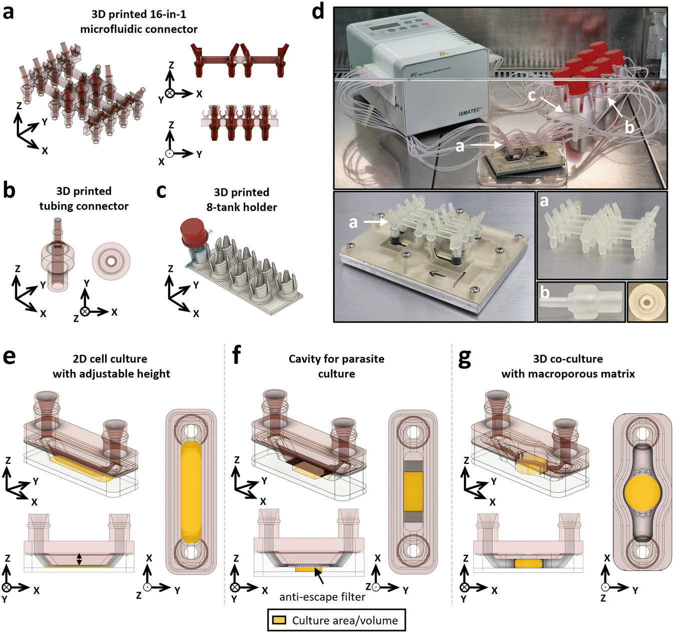 | ||
| Fig. 7 Development of complex microfluidic circuit components and customisable culture chambers using 3D printing. The circuit that connects the eight culture chambers is made up of 3D-printed parts, including (a) the 16-in-1 connector that connects to the adaptors on the cap (inlet and outlet), (b) the tube connectors for connecting the tubes to the tank outlets, and (c) the 8-tank holder. (d) Images of the complete microfluidic system with the (a)–(c) printed parts, combined with tubing, connectors and peristaltic pump. Modularity permitted by 3D printing was evaluated by developing three geometries of the culture chamber: (e) a classic channel with variable height to vary the speed of the flow on a 2D culture, (f) a culture chamber designed to culture a pair of S. mansoni adult worm parasites, delimited by a 70 μm nylon anti-escape filter with the flow passing over it, and (g) a culture chamber in the format of a 96-well plate well to accommodate a macroporous matrix and a flow passing through to cultivate different cell types (epithelial and fibroblastic) and tumoroids. | ||
3D printing shows a high modularity and allows us to easily customise the geometry of the microfluidic chip for specific applications. We therefore produced (i) a 2D cell culture geometry with modifiable height (Fig. 7e), (ii) a parasite culture geometry to host whole living organisms (Fig. 7f) and (iii) a 3D co-culture geometry based on 96-well plate dimensions (Fig. 7g). The overall timeline of the fabrication protocol for these three devices shows that they can be produced within 2 days which considerably reduces manufacturing time compared with soft lithography, which requires the production of an optical mask (Fig. S7†). Three different biological models were cultivated using these geometries: (i) a 2D co-culture of epithelial HPAC-eGFP and fibroblastic PS-1-TD Tomato pancreatic cancer cells with two different culture chamber heights (600 and 2400 μm) to produce different flow velocity profiles (Fig. 8a), (ii) a Schistosoma mansoni adult worms culture (Fig. 8e) and (iii) a 3D co-culture of PaTa-1818x pancreatic patient-derived tumoroids with fibroblastic PS-1-TD Tomato cells in a macroporous matrix (Fig. 8h).
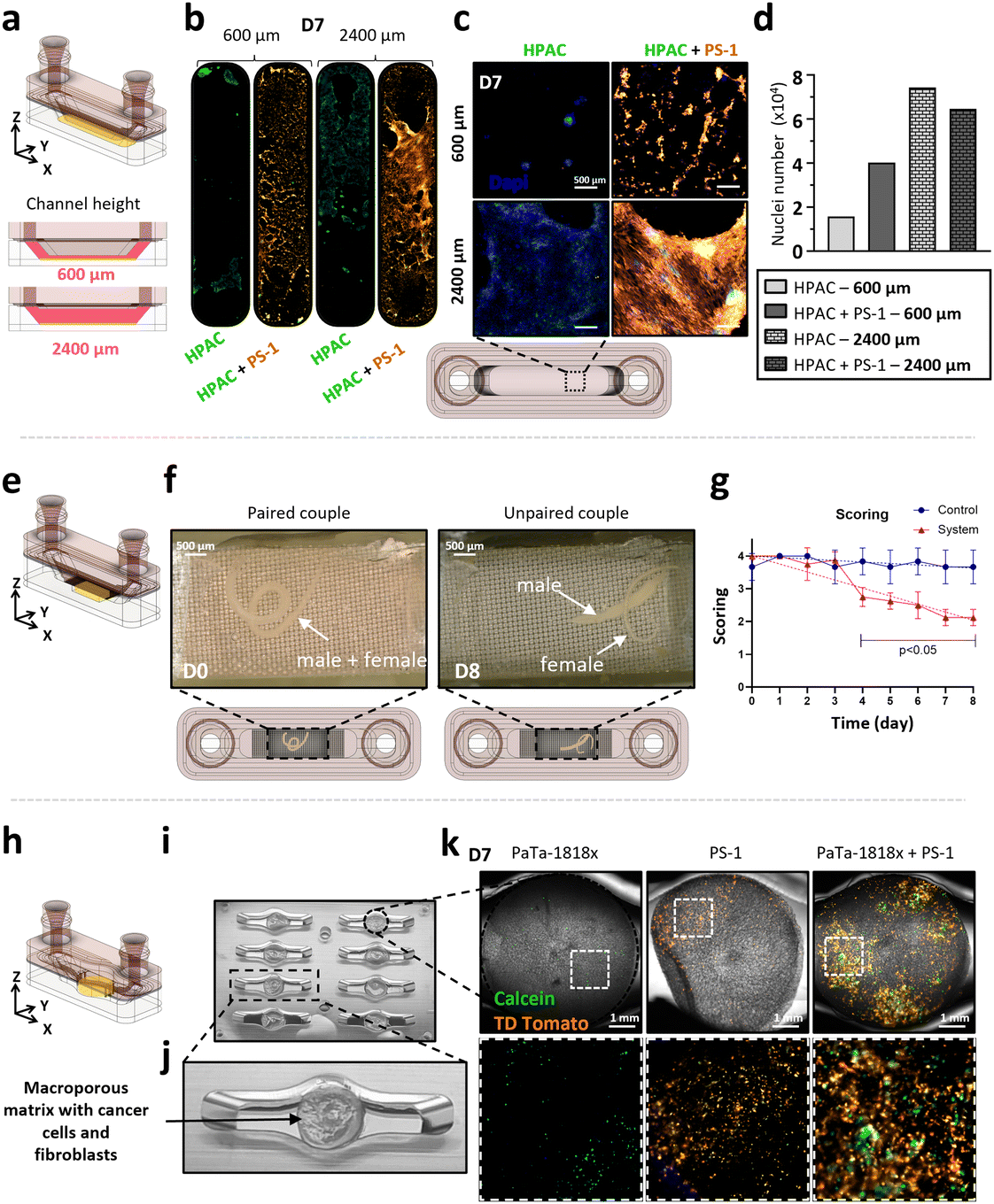 | ||
| Fig. 8 Application of the microfluidic chamber geometries to 2D, 3D human cell co-culture and worm culture. The first geometry (a) is a simple channel whose height has been adjusted at 600 and 2400 μm to modulate the flow velocity. HPAC-eGFP cells were grown in either monoculture or cocultured with PS-1-TDTomato for 7 days. (b) Full channel imaging, (c) channel zoom and (d) nuclei counting (DAPI staining) (n = 1). The second geometry (e) allows a pair of motile S. mansoni adult worm parasites to be enclosed while feeding on the perfused culture medium. The pairs were cultured for 8 days and their condition assessed every day. (f) Images of the parasites on day 0 and day 8 and (g) assessment of their health status (/4) during culture (n = 1). The third geometry (h) is the size of a 96-well plate well and allows the integration of a macroporous culture matrix (i and j) to co-culture pancreatic tumoroids (PaTa-1818x) with PS-1-TDTomato cells. (k) After 7 days of monoculture and co-culture, calcein and fibroblasts (TDTomato) were observed. Scale bar = 1 mm. Error bars denote SD. | ||
The flow velocity v (μm s−1), assumed to be uniform on the channel's cross section, is calculated as:
 | (2) |
This allowed us to tune the system design, either the channel height or width, to obtain different flow velocities in the culture chamber and to match the physiological flow conditions of the targeted biological application (Table S5†).
In the first geometry, a morphological difference could be observed between the two channel heights, with fibroblastic PS-1-TD Tomato cells being more activated (larger membrane extensions) in the 2400 μm culture chamber (Fig. 8b and c). With the 600 μm height channel (34.63 μm s−1 averaged flow velocity), nuclei counting showed a higher number of HPAC-eGFP cells at day 7 in coculture when compared to the monoculture (day 0 and 3 available in Fig. S8†). With the 2400 μm height channel (8.66 μm s−1 averaged flow velocity), the number of cells was quite similar in mono- and co-culture, except at day 7 where it was less important in co-culture. Moreover, more cells were observed in both mono- and co-culture in the 2400 μm height channel compared to the 600 μm (Fig. 8c and d).
For the culture of schistosome parasites, one couple of paired adult worms was cultivated in each channel for eight days inside the microfluidic device and compared to a control well plate. The condition of the worms along the culture was determined every 24 h using a five-level scoring method (from “dead” 0 to “normal” 4) (Table S6†). The parasites at day 0, 1 h after seeding, were given a perfect score of 4/4 as they displayed a healthy phenotype with active movements and correct adhesive capacity (Fig. 8f). They stayed paired for the whole duration of the recording and stayed attached to the glass surface even when the device was turned upside down. The same schistosome pair at the end of the experiment (day 8) was given a degraded score of 2/4 as their mobility was strongly reduced and they were detached from the surface, in addition to being unpaired (Fig. 8f). During the culture, the perfect score of 4/4 could be maintained for at least one day. The worms were then kept in excellent condition with a score greater than 3.75/4 for at least two more days (Fig. 8g). As of day 4, a non-negligible degradation of the worms' condition was observed, after which the score decreased linearly from 2.75/4 to 2.13/4 at day 8 (overall −0.25 score per day). This represented a significant difference with the control.
The third model aimed at developing a chip to coculture patient-derived pancreatic tumoroids with pancreatic activated stellate cells within a macroporous matrix. To this aim, the geometry of the culture chamber was transformed from a rectangular shape to a circular configuration (Fig. 8i and j). This modification allowed the seeding of tumoroids and cells in the matrix, their subsequent transfer to the microfluidic device and cultivation over a 7-day period with direct perfusion across the matrix. Calcein AM staining was performed to measure the viability of cells in the device. After a 7-day culture, a limited number of cells in both PaTa-1818x and PS-1 monocultures could be observed (Fig. 8k), whereas when cocultured, a higher cell density was observed (Fig. 8k).
This third model enabled the possibility to open the system (Fig. S9†). After 14 days of a dynamic co-culture of patient-derived pancreatic tumoroids (003T) with PS-1 pancreatic stellate cells (Fig. S9a and b†), the microfluidic chip was opened (Fig. S9c†) and matrixes containing cancer cells and fibroblasts were extracted and immerged in the cryopreservation solution (Fig. S9d†). Samples were then cryogenised and sliced on a cryostat (20 μm thickness) (Fig. S9e†) to dispose slices on slides and perform immunofluorescence staining (Fig. S9f†). Epithelial E-cadherin (Fig. S9g†) and fibroblastic vimentin (Fig. S9h†) expression are shown (green).
Discussion
The development of alternative biological models is now driven by the development of microfluidic systems. They aim at mimicking the physicochemical microenvironment not only of cells but also of more complex and larger organisms. Our aim was to design an easily modifiable and versatile microfluidic device to reliably host various biological models and study their behaviours. As the fabrication of microfluidic systems inherently demands accuracy and reproducibility along with the use of biocompatible materials, 3D printing has been explored as an alternative fabrication technique to overcome the shortcomings of more traditional methods.29In this context, we first assessed the precision of SLA- and LCD-based printers using a tailored CP featuring different geometrical patterns and dimensional ranges. Subsequently, we extended this characterisation to four commercially available resins, to choose the best fit for PDMS moulds (TR300) and constitutive parts (Bio-Med Clear) of the developed system. A SBB surface treatment was used to minimise the constitutive parts' autofluorescence, which facilitated fluorescence-based microscopy imaging. We then assessed the cytotoxicity of the three selected resins. Given the significant residual cytotoxicity observed with the Bio-Med Clear resin, a complementary treatment with parylene C was evaluated and validated to improve its cytocompatibility, thereby validating its integration in the microfluidic chip. These adaptations leveraged the full potential of 3D printing by fabricating intricate components of the parallelised microfluidic chip and its accompanying circuit. In the end, we obtained a versatile device with three distinct culture chamber geometries that allow studies of different biological questions related to cancer or infectiology, cancer cell behaviour, and cell–cell and cell–matrix interactions.
The LCD-based printer has proved easier to use thanks to the overall control over printing parameters provided by the software, in contrast to the SLA printer. We successfully adapted the Precisa 780 resin, originally intended for the SLA printer, and used it in the LCD printer to subsequently characterise the printing errors of both printers. However, as the resin is manufactured for a printer with a much more powerful laser than the LCD's UV lamp, printing times have increased drastically, from 7 h on SLA to 42 h on LCD, making the use of this resin too restrictive. Our characterisation demonstrated that the cheaper LCD-based printer was more accurate in regard to pattern dimension error regardless of printing orientation, which is in agreement with other studies.28
In addition, we evaluated the impact of part orientation during printing. Vertical printing generally resulted in more accurate patterns, which again is in accordance with the literature,30 while horizontal printing allowed minimisation of the surface roughness. This enabled us to choose the printing orientation depending on the targeted application. It is generally accepted that the dimensions of microsystems hosting living cells or organisms are usually of the order of 1 to 1000 μm.31 Below 250 μm, our results showed that printing height accuracy is approximate, whereas assembling larger components allowed forming a channel height of 600 μm successfully with low variability. We have also highlighted that the combined choice of printer, resin and printing orientation has major impacts on the undesired curvature of the printed elements, which can lead to dramatically altered shapes and dimensions. By applying our tailored characterisation protocol, we selected the TR300 resin for the fabrication of PDMS mould as it demonstrated superior precision and is temperature resistant, which is important for PDMS moulding.
Our work showed that Bio-Med Clear resin was the optimal option for ensuring viability with both cell lines. Although the threshold for cytocompatibility is usually set at 80% for biomedical applications,26 we considered this viability still insufficient for long-term incorporation into the chip and its circuit for culture purposes. Several options were explored to increase the resin's cytocompatibility such as modifying the post-printing washing and curing.32 Rather than drifting from the manufacturer's recommendations, we coated our Bio-Med Clear components with parylene C. Indeed, parylene C has previously been shown to improve viability in both short- and long-term cell cultures by forming an insulating protective polymer layer that prevents toxicity phenomena induced by the material.33 This enabled us to enhance the viability of Bio-Med Clear components to over 90% for cell culture (and viable parasite culture, data not shown), approaching that of traditional 2D in vitro culture systems and thus validating our process.34
We also had to improve the quality of fluorescent imaging as we noticed strong autofluorescence when performing fluorescence-based microscopy with Bio-Med Clear components, questioning its use in a microfluidic chip. We therefore decided to treat the resin with SBB, which had been described to reduce the autofluorescence of polymers either by absorbing emitted photons or by changing its refractive index.35 This allowed us to strongly reduce the emission intensity by at least 70% at the wavelengths of interest for these applications, which is consistent with a previously established SBB coating protocol.36 The images obtained thereafter were more contrasted and allowed precise nuclei counting.
Parallelised microfluidic systems on varying scales (channel number) are a hot topic since they enable a larger number of experiments or conditions to be carried out simultaneously on more complex models, limiting bias of sequential experiments.29 Our established fabrication protocol enabled the design of a parallelised chip geometry compatible with SBS standard (96 well plate) incorporating a dedicated closing system. In contrast to commercially available parallelised microfluidic systems, we have shown that we could easily adapt the connection between the circuit and our device, demonstrating the capability of 3D printing to control all aspects of a microfluidic platform compared to other fabrication methods (SU-8 lithography, aluminium milling). This was facilitated by the fabrication of complex 3D-printed components, such as the 16-in-1 connector. To ensure long-term culture, a closed circuit was used featuring an adequate volume of culture medium alongside a peristaltic pump to facilitate the dynamic perfusion within the system. This allowed for the recirculation of the medium, saving a considerable volume (3.5 mL in a closed loop vs. 37.5 mL for an open circuit with 3.74 μL min−1 flow rate) and allowing continuous actuation of metabolites.
Our final goal being to design a modular microfluidic device usable for different biological applications in different biological fields, we wanted to have the possibility to easily adapt the geometry of the device by using 3D printing. To this end, we studied the impact of different flow velocities on 2D cultures, previously performed on endothelial cells.37 Our study on epithelial cells showed that their proliferative and adhesive properties were enhanced in the presence of stellate cells or when the flow velocity decreased. By applying different flow velocities, we mimicked the heterogeneous interstitial flows present in solid tumours.38,39 Thus, the versatility of our system allows the use of a wide range of flow velocities and their application to various cell types. In particular, we showed that this system is particularly suited to study and understand the interactions between tumour and fibroblastic cells, with the example of human pancreatic epithelial cancer cells and pancreatic stellate cells.
Another advantage of our system is the possibility to integrate a synthetic macroporous matrix that is not degraded when subjected to a direct flow,40 as it is an important factor in tumour response to treatments and tumour drug resistance.41 This enabled us to implement dynamic culture conditions to our 3D co-culture model of human pancreatic tumoroids and pancreatic stellate cells. In these conditions, tumoroids were more resistant to the applied flow when co-cultured compared to monoculture. This preliminary result opens the way to studies aiming at evaluating the behaviour of tumoroids when subjected to a flow. This device could thus allow more valuable and relevant studies aimed at investigating cell–cell and cell–matrix interactions in a co-culture system subjected to an interstitial flow and measure tumour chemoresistance and aggressiveness when submitted to chemotherapeutic drugs.
Regarding the needs in microbiology and infectious diseases research, the microfluidic device geometry was also adapted to culture S. mansoni parasitic adult worms for several days. Worms have much larger dimensions than tumoroids and are able to move into the system against or with the flow. To make its integration possible, the culture chamber was delimited by an anti-escape filter in the channel. With that adaptation, the device can be used to study parasite biology and behaviour in dynamic culture conditions, for instance egg production, couple pairing and viability, and worm potential interactions with cells from the host. The study of this parasite in a dynamic in vitro environment mimicking a blood vein is highly original. The few studies that have been published addressed the larvae stage.42 Our microsystem makes it possible to screen the action of antiparasitic molecules, as has already been done in other microfluidic systems for the parasites S. mansoni43 or C. elegans.44
As our system is made up of two separable parts, we intend in future studies to open it for biological analyses and perform protein or RNA extraction that are difficult to do when the system is closed. For example, it has been shown that atomic force microscopy analyses can be carried out using an openable device, which is impossible when the system is closed.45,46
Conclusion
We have developed a new versatile 3D microfluidic device using LCD-based 3D printing with TR300 resin for PDMS moulding and Bio-Med Clear resin for constitutive parts. We treated Bio-Med Clear parts to decrease its cytotoxicity and autofluorescence and then validated the use of the device for different biological applications. This device is also adapted to modern robotics and microscopes with new and tailor-made culture chamber geometries. Overall, this versatile microfluidic platform can be used to study various complex biological models and establish dynamic culture conditions, allowing one to address a variety of use and applications in many biological fields, such as cancer or infectiology.Materials and methods
Design and printing process
All the components were conceptualised using Autodesk Fusion 360 Computer-Aided Design (CAD) software (version 2.0.20256 x86_64). The 3D files were then exported in stereolithography (STL) format and prepared for printing in the CHITUBOX Basic software (version 2.1). Specifically, the parts to be printed were virtually positioned on the printing plate and a raft was placed as a base to facilitate detachment. Furthermore, pillars were placed as a support to ensure printing of all the parts' details. The printing parameters were then chosen depending on the resin used (Table S7†) and a ‘.fictor and .nauta’ and ‘.ctb’ file was created and transferred to the printer, based on either SLA (DWS, Thiene, Italy, XFAB 2000) or LCD (Phrozen, Hsinchu, Taiwan, Sonic Mini 8K) technology.Once printing was complete, the parts were lifted off the printing plate and separated from the construction pillars. The post-printing process depended on the resin used; details are given in Table S8.† Briefly, the parts were cleaned with isopropyl alcohol (IPA) (VWR, West Chester, PA, USA, 20922.368) in a propeller bath (Formlabs, Somerville, MA, USA, Form Wash) or ultrasound cleaner (Vevor, France, 020) followed by drying with compressed air. The parts were then left to dry for about 30 min before being put in a UV oven (Formlabs, Form Cure) to reticulate the resin. To ensure the manufacturer's properties of each resin, including biocompatibility, one single vat was associated to each resin, and IPA used for cleaning was not mixed between resins. Both temperature and hygrometry were recorded regularly in the printing room over a 3-month period using a digital thermometer and hygrometer (Atome 3D, Toulouse, France, AFAI1040). The obtained temperature was pretty stable over time with an average of 20.82 °C as the laboratory is heat-regulated, with only local variations mainly due to day/night cycle and current weather (Fig. S10†). The hydrometry increased over time due to the seasonal weather changes, with an average of 44.97%.
System fabrication process
The bottom closing plate and wedge were made by machining aluminium using a Computer Numerical Control (CNC) milling machine (Datron, Annecy, France, Datron Neo). The aluminium plate (RS, 188-321) was placed in the milling machine and held in place with a vacuum plate. The desired patterns were then produced according to the previously created Fusion 360 design files, using micro-end mills (Datron, 0068020E). The upper closing plate was 3D printed in Bio-Med Clear resin. The lower part of the microfluidic chip was fabricated in polymerised polydimethylsiloxane by mixing Sylgard 184 Silicone Elastomer and the corresponding curing agent at a 10![[thin space (1/6-em)]](https://www.rsc.org/images/entities/char_2009.gif) :1 (w/w) ratio. The solution was then mixed and degassed for 30 min. The solution was then poured into the master moulds, which were closed using a set of 3D-printed rings that held a 200 μm thick polyvinyl chloride (PVC) sheet (Fellowes Brands, Itasca, IL, USA, CRC53761), ensuring a smooth surface after demoulding. The mould was then degassed for an additional 20 min, then placed in an oven (Virtus GmbH, Hamm, Germany, 5695TD) at 70 °C for 3 h as the glass temperature of PVC is 73.4 °C. Once cured, the PDMS was demoulded using a scalpel and tweezers and washed for 3 min in IPA using an ultrasonic cleaner. To complete the process, the PDMS chip was bonded to a glass substrate after exposure to an oxygen (O2) plasma (Harrick Plasma, Ithaca, NY, USA, PDC-002-CE) for 60 s and subsequently placed on a hot plate at 120 °C for 2 min.
:1 (w/w) ratio. The solution was then mixed and degassed for 30 min. The solution was then poured into the master moulds, which were closed using a set of 3D-printed rings that held a 200 μm thick polyvinyl chloride (PVC) sheet (Fellowes Brands, Itasca, IL, USA, CRC53761), ensuring a smooth surface after demoulding. The mould was then degassed for an additional 20 min, then placed in an oven (Virtus GmbH, Hamm, Germany, 5695TD) at 70 °C for 3 h as the glass temperature of PVC is 73.4 °C. Once cured, the PDMS was demoulded using a scalpel and tweezers and washed for 3 min in IPA using an ultrasonic cleaner. To complete the process, the PDMS chip was bonded to a glass substrate after exposure to an oxygen (O2) plasma (Harrick Plasma, Ithaca, NY, USA, PDC-002-CE) for 60 s and subsequently placed on a hot plate at 120 °C for 2 min.
Characterisation platform design
A characterisation platform (CP) was designed and produced in both horizontal and vertical orientations to assess the dimensional precision of the printer. Protrusions and cavities were designed to assess the printing precision in both the positive and negative directions, ranging from 50 to 5000 μm in height and 2 mm constant width (for 10 mm base length). Additionally, cylindrical and punch-shaped features were incorporated to assess the integrity of pillars and holes as well as the precision in diameter dimensions, ranging from 50 to 5000 μm in diameter for 2 mm constant height. Angled and inverted-angled structures were employed to evaluate the accuracy of slope reproduction during printing in both printing orientations, ranging from 100° to 160° and from 20° to 80°, respectively. The details of the size ranges for each pattern type are given in Table S9.† The platform also included a designated flat surface area without any specific pattern for conducting average surface roughness measurements. The platforms were printed in triplicate for each printer and resin (DWS, Precisa 780; Phrozen, TR300 Ultra-High-Temp; Phrozen, Aqua-Clear; Liqcreate, Bio-Med Clear).Characterisation of printing precision using a digital microscope
The dimensions of the produced CPs were measured using a digital microscope (Keyence, Osaka, Japan, VHX-7000) also allowing 3D profiles of the imaged object. Protrusions, cavities and angles were imaged as 3D acquisitions, using 100× magnification, with complete annular, complete coaxial, and lower annular illumination. The cylinders and punches were imaged as 2D acquisitions using 50× magnification with complete annular illumination. Inverted angles were measured in the same manner as cylinders and punches but with the characterisation platform wedged vertically under the objective. For all the acquisitions, the whole range of a pattern type was imaged all at once by assembling images along a 40 mm linear track. Following the measurements, raw data were then exported in comma-separated values (CSV) files to be analysed (Fig. S11†). From the raw pattern measurements, the absolute error compared to the design was calculated for all pattern sizes (Fig. S12†). For the cavities, the measurements corresponding to the 5000 μm height were not considered because for most of the replicates the cavities were breached due to insufficient platform width. The measurements of the protrusions and cavities heights were considered characteristic of the printers' and resins' precision in both the Z-axis (height) and the XY-axis (surface pattern) for horizontal and vertical printing orientations, respectively. Protrusions were considered positive patterns as they were additive to the platform bulk, and cavities negative as they were subtractive. That defines the four-dimensional indicators used for the precision comparisons (Table S10†). Following the characterisation of the dimensions of the produced CPs, the microfluidic devices were assembled and closed using aluminium plates. The culture chambers were then imaged as 3D acquisitions using 100× magnification with complete annular illumination to extract their resulting height.Curvature characterisation
CP curvature was analysed using a VHX-7000 microscope using 50× magnification with complete annular illumination for each replicate. The height profile measurement was performed along a line following the whole edge using the microscope integrated software, and data were directly exported in CSV files. Data were processed automatically using a custom Python script that extracts the height profiles and calculates for each one the area between the profile and a straight line connecting its ends by cumulating the point-to-point difference. This area is considered representative of the curvature of the platform (Fig. S13†), thus allowing prevention of the impact of the imperfect horizontality of the CPs under the microscope objective during the measurement.Profilometer surface roughness evaluation
The surface roughness of CPs was evaluated using a stylus profiler (KLA Instruments, Milpitas, CA, USA, Alpha-Step® D-600 Stylus) with a tip diameter of 2 μm. The measurements were realised with a stylus force of 15 mg over a length of 1 mm and at a speed of 0.05 mm s−1. For each platform, six measurements (three horizontal and three vertical measurements) were carried out (Fig. S14†). All the profiles were then determined and analysed using a custom-made Python script to extract the average roughness Ra based on the definition by The American Society of Mechanical Engineers.47 The surface roughness was also imaged using a digital microscope (Fig. S2†).Sudan Black B and parylene C device treatment
0.3% (w/v) Sudan Black B (SBB) (Sigma-Aldrich, St. Louis, MO, USA, 199664-25G) solution was prepared as described.48 The 3D-printed objects were exposed to O2 plasma for 60 s and immersed in the SBB solution overnight at 4 °C. After staining, the objects were rinsed in 1× phosphate-buffered saline (PBS) (Gibco, Grand Island, NY, USA, 14190-144) three times, then sterilised by UV exposure for 30 min. Thin film parylene C coating was done by depositing a 2 μm thick parylene C (Specialty Coating Systems, Indianapolis, IN, USA, 28804-46-8) film using SCS Labcoter 2 parylene C deposition system (Specialty Coating Systems, PDS 2010). Briefly, 4 g of DPX-C was placed in a vaporizer under vacuum. The process began at a base chamber pressure of 7 mTorr, and the furnace was heated to a temperature of 690 °C, after which the vaporizer was ramped up to 175 °C to sublime the dimer which is then deposited onto the component.Resin fluorescence assessment
The emission spectrum of Bio-Med Clear resin was analysed using pellets of the size of a 24-well plate (15 mm diameter and 3 mm height). These pellets were printed, treated or not with SBB and placed in conventional 24-well culture plates (Falcon, 353047). The spectrum was obtained by exciting the resin at 388, 469 and 567 nm, and the emission intensity was read every 2 nm from 408 to 800 nm, 489 to 799 nm and 587 to 799 nm, respectively (Perkin Elmer, Waltham, MA, USA, EnSpire Multimode Plate Reader).Resin cytotoxicity assessment using resazurin assay
To assess the cytotoxicity of the resins, wells based on the size of a 96-well plate (Falcon, 353072) made from 3D printing resins were created. 3D-printed inserts of each resin (Aqua-Clear, TR300 and Bio-Med Clear) were produced to fit into a 48-well plate (Falcon, 353078) to replicate a 96-well plate well's dimensions. The dimensions of the insert were as follows: 9.70 and 10.00 mm bottom and top outer diameters; 6.35 and 6.85 mm top and bottom inner diameters, respectively. The inserts were bonded to a 48-well plate using PDMS. HPAC-eGFP (17 × 103) and PS-1-TD Tomato (8 × 10³) cells were seeded and cultured for 48 h. Follow-up imaging was carried out at 24 and 48 h. After 48 h, a resazurin viability assay was performed and a double absorbance reading at 595 and 570 nm was taken after 16 h. The 570 nm reading was subtracted from the 595 nm reading and the values were compared with the control, which consisted of cells cultured with no 3D-printed components. A 10% (v/v) resazurin solution (150 mg mL−1 resazurin (Sigma-Aldrich, #R7017), 25 mg mL−1 methylene blue (Sigma-Aldrich, #MB-1), 329 mg mL−1 potassium hexacyanoferrate(III) (Sigma-Aldrich, #P8131) and 422 mg mL−1 potassium hexacyanoferrate(II) trihydrate (Sigma-Aldrich, #P9387)) were used.Microfluidic setup
The microfluidic device and circuits were prepared, washed and sterilised by autoclaving prior to each experiment. One circuit consisted of a 16-in-1 connector for connecting the eight pairs of fluidic inputs and outputs of the device, a glass medium reservoir (MOD'VERRE, Grasse, France, custom-made), 1.6 mm tubes (Ibidi®, Gräfelfing, Germany, 10842), 0.5 to 1.6 mm adaptors (Ibidi®, 10829), and a peristaltic pump (Ismatec™, Glattbrugg, Switzerland, ISM930A). The circuits were closed without the devices at first and connected to the running peristaltic pump (Ismatec™, IPC-N8 ISM936) to fill the tubing with medium. Then, the device was carefully closed and constrained using the screwed closing plates. After cell, tumoroid or parasite seeding, the reservoirs were filled with 3.5 mL of the respective culture medium. The circuits were then connected to the device and the peristaltic pump (0.5 mm tubing, Ibidi®, 10840) for flow actuation.Fluorescein flow rate assay
An in-line injection port (Ibidi®, Germany) was fitted in the microfluidic circuit at the inlet of the device, and the circuit was subsequently filled with 3 mL of DI water. A solution of DI water containing fluorescein powder (Sigma-Aldrich, USA) was prepared at 4.26 × 10⁻¹⁰ mol m−3. The solution was aspirated in a 1 mL syringe which was fitted with a needle (Terumo®, Japan) used to pierce the silicone septum to inject a 100 μL bolus of the fluorescein solution. The flow was established by an IPC High precision multichannel pump (Ismatec®, Switzerland) at the prescribed flow rate (3.74 mL min−1). Imaging was performed on a DMI8 microscope (Leica Microsystems, Germany) from flow actuation for 40 min. The peak of fluorescence intensity was observed at 30 min and thus images at this time point were extracted.Human pancreatic cancer cell lines
All cell types were cultured at 37 °C in a 5% CO2 humid atmosphere incubator. The HPAC pancreatic cancer cell line (ATCC® CRL-2119™) was cultured in Dulbecco's modified Eagle medium (DMEM) (Gibco, 41965-039) supplemented with 10% (v/v) foetal bovine serum (FBS) (Gibco, 10270-106), 2 mM glutamine (Gibco, 25030-024), and penicillin (100 IU mL−1)–streptomycin (100 μg mL−1) (Gibco, 15140-122). Human pancreatic stellate cells (PS-1) (UK Human Tissue Bank (ethics approval; Trent MREC, 05/MRE04/82)) were cultured as previously described (Froeling et al. 200953). The HPAC and PS-1 cell lines were genetically modified to respectively express the green fluorescent protein (HPAC-eGFP) and the TD Tomato protein (PS-1-TD Tomato) (Vect'UB vectorology platform, TBM Core, UMS3427, University of Bordeaux).Human pancreatic tumoroids
The human pancreatic tumoroids PaTa-1818x and PDAC 003T were cultured at 37 °C in a 5% CO2 humid atmosphere incubator as previously described.49 They were mechanically and enzymatically dissociated every fortnight as previously described.50S. mansoni material and culture
All animal experimentations were conducted in accordance with the Guidelines of European Convention for the Protection of Vertebrate Animals used for Experimental and other Scientific Purposes (ETS no. 123, revised Appendix A) and were approved by the local committee for ethics in animal experimentation (authorization no. APAFIS #37320-2022051208133098v3) and the Pasteur Institute of Lille (agreement no. B59350009). A Puerto Rican strain of S. mansoni was maintained in the laboratory using the intermediate snail host Biomphalaria glabrata and the definitive golden hamster host Mesocricetus auratus. Adult schistosome worms were obtained by hepatic portal perfusion of hamsters 6 weeks after infection by cercariae released from infected snails. Perfused worms were maintained as previously described until further use.432D culture in the microfluidic device
To evaluate the proliferation of HPAC-eGFP and PS-1-TD Tomato cells in 2D under different flow velocity profiles, the height of the cap was modified to have chambers with heights of 600 μm and 2400 μm, respectively. After trypsin detachment, cells (2 × 10⁴ HPAC-eGFP and 2 × 10⁴ PS-1-TD Tomato in monoculture; 4 × 10³ HPAC-eGFP and 1.6 × 10⁴ PS-1-TD Tomato in coculture) were seeded after complete closure of the device in a culture medium volume of 100 μL. The chip was incubated for 24 h to allow the cells to attach properly to the glass substrate, after which a 3.74 μL min−1 flow rate was delivered with the peristaltic pump. Cells were subsequently cultured for 7 days. Follow-up imaging was carried out at days 0, 3 and 7 using an automated fluorescence microscope (ZEISS, Oberkochen, Germany, Cell Discover 7). Nuclei (DAPI staining) were counted using Zeiss Zen Blue 3.5 software and the Image analysis pack.3D culture in the microfluidic device
To enable the culture of PaTa-1818x tumoroids in a macroporous matrix (HCS Pharma, BIOMIMESYS® custom), the geometry of the culture chamber was modified to a circular 96-well plate format (6 mm diameter, 2 mm high). After trypsin detachment, cells (2 × 10⁴ PaTa-1818x and 4 × 10⁴ PS-1-TD Tomato in monoculture; 2 × 10⁴ PaTa-1818x and 4 × 10⁴ PS-1-TD Tomato in coculture) were seeded in 10 μL of culture medium in the lyophilised macroporous matrix and incubated for 24 h for proper attachment.51 After 24 h, the matrixes were removed from the 96-well plate with tweezers and placed in the opened microfluidic device culture chamber. The microfluidic device was then closed and connected to the circuit, after which a 3.74 μL min−1 flow was delivered with the peristaltic pump. The cells were subsequently cultured for 7 days. Follow-up imaging was carried out at days 0 and 7 using an automated fluorescence microscope (ZEISS, Cell Discover 7).Cryopreservation of samples
At the end of the microfluidic culture, the microfluidic system was opened and the biological samples (porous matrixes containing tumoroids and fibroblasts) were transferred into cupules (25 mm × 20 mm × 5 mm Tissue-Tek®, 4557) using tweezers. For cryogenisation, a cryopreservation solution (Tissue-Tek®, 4583) was applied to the samples and cryogenisation is carried out in a bath at −80 °C (Snapfrost, Excilone). The blocks obtained were stored at −80 °C until use. 20 μm sections were taken using a cryostat (Epredia™ CryoStar™, NX50) and placed on a TOMO slide (Matsunami, TOM-1190), after which they were stained or stored at −20 °C until immunostaining.Immunostaining
Biomarker expression analysis was performed on 20 μm sections using specific antibodies. A permeabilising solution (0.1% (v/v) Triton X-100 in 1× PBS) was used for 20 min at room temperature. Slides were then incubated with primary antibodies at 4 °C overnight (Cell Signaling Technology, E-cadherin #14472; vimentin #5741). The appropriate fluorochrome-coupled secondary antibodies (Alexa Fluor 488, A32731) were added for 1 h at room temperature and in the dark along with DAPI staining. To reduce non-specific labelling, antibody solutions were prepared in 1% (w/v) bovine serum albumin in 1× PBS. Between each immunostaining step (fixation, permeabilisation, primary antibody, secondary antibody), the slides were rinsed three times with 1× PBS. Finally, the slides were covered with a coverslip and imaged under a fluorescence microscope (Zeiss, AxioImager).Parasite culture in the microfluidic device
To enable the culture of schistosome adult worms (up to 10 mm long and 500 μm large), a culture chamber (6 mm long, 1 mm high and 3 mm wide) was added at the centre of the channel. The design of the other parts of the closing system was adapted to the change in height of the device. To prevent worms from escaping the culture chamber, a 70 μm nylon filter was extracted from cell strainers (Falcon, 352350) and shaped precisely to the channel size using a scalpel. Hollow extensions (600 μm high, 1.7 mm long, 3 mm wide, 200 μm thick) were added on the top part design on each extremity of the channel. A cut filter piece was bound on those extensions' bottom surface using Bio-Med Clear 3D printing resin, which was solidified by UV reticulation for 1 h and treated with parylene C for toxicity prevention, to cover the whole culture chamber. 30 μL of medium was then added in the culture chamber before one adult worm pair was deposited in each channel, using a low-retention pinch to minimize worm damage. The circuit was then closed and 3 mL of medium was filled in the tanks, and the peristaltic pump was set to deliver a 73.9 μL min−1 flow rate. The worms were monitored every 24 h for 8 days. A control was realised by culturing one adult worm pair per 12-well plate well with 3 mL of medium over the same culture time.Evaluation of parasite condition by scoring
The viability of the worms was evaluated using a VHX-7000 microscope with a 45 s video of the worm pair at 50× magnification. The condition of the worms was determined using a phenotypic scoring method, a method classically used for the screening of antischistosomal drugs.52 A five-level scale was defined: S4 score as normal healthy condition for worms having active movements, correct adhesive capacity, normal tissues and tegument integrity; S3 score as reduced condition was defined by reduction of movement or abnormal ones and/or the loss of adhesive capacity, or the appearance of anomalous morphological changes; S2 score as degraded condition corresponded to worms with severely reduced activity, displaying only occasional extremities movements; S1 score as minimal condition denoted worms with no external movement, but still displaying an internal activity evaluated by observing gut peristalsis; S0 score as dead condition referred to worms having no movement at all, external or internal, with tissue and tegument degradation. The complete criteria used to determine worm condition during culture are presented in Table S6.†Statistical analysis
Statistical analyses were carried out using GraphPad Prism 8.0.2 software. Normality and homoscedasticity for the data were checked for each performed statistical test using quantile–quantile and residual plots, respectively. Depending on these results, appropriate parametric or non-parametric tests were chosen. Errors for the different printers and resins depending on the pattern size were analysed using two-way ANOVA followed by Tukey's tests. The overall printer and resin precision, CP curvature, average surface roughness, the area under the curve representing decrease in fluorescence emission, and PS-1-TD Tomato viability were analysed using one-way ANOVA followed by Tukey's tests. Average assembled culture chamber heights were analysed using an unpaired t-test. HPAC-eGFP cell viability was analysed using a Brown–Forsythe and Welch one-way ANOVA followed by Games–Howell's tests. The condition of the worms in the microfluidic system was analysed using repeated measures two-way ANOVA followed by Bonferroni's tests for parametric and homoscedastic data, and sphericity assumption. A p < 0.05 value was considered statistically significant and was denoted with * for p < 0.05, ** for p < 0.01, *** for p < 0.001 and # for p < 0.0001. Data are represented as mean ± standard deviation. The number of replicates is described in each figure legend.Data availability
The raw data of the work presented in the manuscript entitled “Fabrication of a bioreactor combining soft lithography and vat photopolymerisation to study tissues and multicellular organisms under dynamic culture conditions” by T. Meynard et al. are available at https://doi.org/10.5281/zenodo.14866978.Author contributions
Conceptualisation: T. M., F. R., R. H., O. B., I. V. S., V. S. Methodology: T. M., F. R., R. H., O. B., S. P., F. L., V. S. Validation: T. M., F. R., R. H., O. B., J. V., I. V. S., V. S. Formal analysis: T. M., F. R., R. H., O. B. Investigation: T. M., F. R., R. H., O. B., S. P. Resources: A. M. V., N. M., J. V., I. V. S., V. S. Writing – original draft preparation: T. M., F. R., R. H., O. B. Writing – review and editing: T. M., F. R., R. H., O. B., J. V., I. V. S. Supervision: J. V., I. V. S., V. S. Project administration: I. V. S., V. S. Funding acquisition: N. M., J. V., I. V. S., V. S. All authors have read and agreed to the published version of the manuscript.Conflicts of interest
There are no conflicts to declare.Acknowledgements
We thank staff of the BICeL cell imaging facility (Dr. Meryem Tardivel, Dr. Antonino Bongiovanni, UAR2014-US41, University of Lille) for access to the equipment and for the technical advice provided. We thank the Vect-UB facility (Jennifer Cattiaux, Dr. Véronique Guyonnet-Dupeyrat, CNRS UMS3427 – Inserm US005, University of Bordeaux) for generating the genetically modified HPAC and PS-1 cell lines. We thank Dr. Mathieu Gautier (UPJV, Amiens) for the kind gift of PS-1 cells. We also thank sincerely Dr. Nelson Dusetti (CRCM U1068, Inserm), Dr. Anthony Trezeibre (IEMN, UMR8520, University of Lille), Dr. Jean-Claude Gerbedoen (LIMMS, IRL2820, CNRS-University of Tokyo), OrgaRES Consortium, Dr. Karin Sahmer (LGCgE, ULR4515, JUNIA-Lille), Dr. Elsa Hadj Bachir, Mr. Anthony Leroy, and Mr. Julien Meynard for their contribution to the project. We thank the ONCOLille institute. This research was funded by the Cancéropôle Nord-Ouest (V. S.), the Région Hauts-de-France (V. S.), CNRS (MITI 80 PRIME, I. V. S.), Inserm and University of Lille. It was also supported by grants from the Ligue Nationale Contre le Cancer (Comité départemental de l'Oise, V. S.), from Agence Nationale de la Recherche (ANR-21-CE19-0049, V. S. & J. V.), from “Contrat de Plan Etat Région” CPER Cancer 2007-2014 and 2015-2020 (I. V. S. & V. S.), from the European Union's Horizon 2020 research (H2020 MSCA COFUND 2018) and innovation program under the Marie Skołdowska-Curie grant agreement No. 847568 (V. S.), from Agilent's University Relations Program (V. S.), and from France Relance recovery plan (V. S.). The Research Council of Norway is acknowledged for the support to the Norwegian Micro- and Nano-Fabrication Facility, NorFab, project number 295864. Finally, this work was partly supported by the French RENATECH network.Notes and references
- J. El-Ali, P. K. Sorger and K. F. Jensen, Cells on chips, Nature, 2006, 442(7101), 403–411 CrossRef CAS PubMed.
- A. R. Wheeler, W. R. Throndset, R. J. Whelan, A. M. Leach, R. N. Zare and Y. H. Liao, et al., Microfluidic Device for Single-Cell Analysis, Anal. Chem., 2003, 75(14), 3581–3586 CrossRef CAS PubMed.
- S. N. Bhatia and D. E. Ingber, Microfluidic organs-on-chips, Nat. Biotechnol., 2014, 32(8), 760–772 CrossRef CAS.
- F. Pampaloni, E. G. Reynaud and E. H. K. Stelzer, The third dimension bridges the gap between cell culture and live tissue, Nat. Rev. Mol. Cell Biol., 2007, 8(10), 839–845 CrossRef CAS PubMed.
- N. Frey, U. M. Sönmez, J. Minden and P. LeDuc, Microfluidics for understanding model organisms, Nat. Commun., 2022, 13(1), 3195 CrossRef PubMed.
- H. Becker and C. Gärtner, Polymer microfabrication technologies for microfluidic systems, Anal. Bioanal. Chem., 2008, 390(1), 89–111 CrossRef CAS PubMed.
- D. Nilsson, S. Jensen and A. Menon, Fabrication of silicon molds for polymer optics, J. Micromech. Microeng., 2003, 13(4), S57 CrossRef CAS.
- D. J. Guckenberger, T. E. Groot de, A. M. D. Wan, D. J. Beebe and E. W. K. Young, Micromilling: a method for ultra-rapid prototyping of plastic microfluidic devices, Lab Chip, 2015, 15(11), 2364–2378 RSC.
- T. Masuzawa, State of the Art of Micromachining, CIRP Ann., 2000, 49(2), 473–488 CrossRef.
- C. G. Khan Malek, Laser processing for bio-microfluidics applications (part I), Anal. Bioanal. Chem., 2006, 385(8), 1351–1361 CrossRef CAS PubMed.
- W. Bacher, K. Bade, B. Matthis, M. Saumer and R. Schwarz, Fabrication of LIGA mold inserts, Microsyst. Technol., 1998, 4(3), 117–119 CrossRef.
- N. Asakawa, T. Shimizu, Y. Tsuda, S. Sekiya, T. Sasagawa and M. Yamato, et al., Pre-vascularization of in vitro three-dimensional tissues created by cell sheet engineering, Biomaterials, 2010, 31(14), 3903–3909 CrossRef CAS.
- A. Bonyár, H. Sántha, B. Ring, M. Varga, J. Gábor Kovács and G. Harsányi, 3D Rapid Prototyping Technology (RPT) as a powerful tool in microfluidic development, Procedia Eng., 2010, 5, 291–294 CrossRef.
- G. I. J. Salentijn, P. E. Oomen, M. Grajewski and E. Verpoorte, Fused Deposition Modeling 3D Printing for (Bio)analytical Device Fabrication: Procedures, Materials, and Applications, Anal. Chem., 2017, 89(13), 7053–7061 CrossRef CAS PubMed.
- H. Kodama, Automatic method for fabricating a three-dimensional plastic model with photo-hardening polymer, Rev. Sci. Instrum., 1981, 52(11), 1770–1773 CrossRef.
- C. W. Hull, Apparatus for production of three-dimensional objects by stereolithography, US4575330A, 1986, [cited 2024 Dec 14], Available from: https://patents.google.com/patent/US4575330A/en.
- S. Maruo, O. Nakamura and S. Kawata, Three-dimensional microfabrication with two-photon-absorbed photopolymerization, Opt. Lett., 1997, 22(2), 132–134 CrossRef CAS PubMed.
- Y. Lu, G. Mapili, G. Suhali, S. Chen and K. Roy, A digital micro-mirror device-based system for the microfabrication of complex, spatially patterned tissue engineering scaffolds, J. Biomed. Mater. Res., Part A, 2006, 77(2), 396–405 CrossRef.
- M. G. A. Mohamed, H. Kumar, Z. Wang, N. Martin, B. Mills and K. Kim, Rapid and Inexpensive Fabrication of Multi-Depth Microfluidic Device using High-Resolution LCD Stereolithographic 3D Printing, J. Manuf. Mater. Process, 2019, 3(1), 26 Search PubMed.
- H. Goodarzi Hosseinabadi, E. Dogan, A. K. Miri and L. Ionov, Digital Light Processing Bioprinting Advances for Microtissue Models, ACS Biomater. Sci. Eng., 2022, 8(4), 1381–1395 CrossRef CAS PubMed.
- US Pharmacopeia (USP) [Internet]. [cited 2024 Dec 31], Available from: https://www.usp.org/.
- ISO - International Organization for Standardization [Internet]. ISO, 2024, [cited 2024 Dec 31], Available from: https://www.iso.org/home.html.
- C. Guttridge, A. Shannon, A. O'Sullivan, K. J. O'Sullivan and L. W. O'Sullivan, Biocompatible 3D printing resins for medical applications: A review of marketed intended use, biocompatibility certification, and post-processing guidance, Ann. 3D Printed Med., 2022, 5, 100044 CrossRef.
- A. V. Nielsen, M. J. Beauchamp, G. P. Nordin and A. T. Woolley, 3D Printed Microfluidics, Annu. Rev. Anal. Chem., 2020, 13(1), 45–65 CrossRef.
- M. D. Poskus, T. Wang, Y. Deng, S. Borcherding, J. Atkinson and I. K. Zervantonakis, Fabrication of 3D-printed molds for polydimethylsiloxane-based microfluidic devices using a liquid crystal display-based vat photopolymerization process: printing quality, drug response and 3D invasion cell culture assays, Microsyst. Nanoeng., 2023, 9(1), 1–15 CrossRef PubMed.
- H. Shafique, V. Karamzadeh, G. Kim, M. L. Shen, Y. Morocz and A. Sohrabi-Kashani, et al., High-resolution low-cost LCD 3D printing for microfluidics and organ-on-a-chip devices, Lab Chip, 2024, 24, 2774–2790 RSC.
- C. Hagemann, M. C. D. Bailey, E. Carraro, K. S. Stankevich, V. M. Lionello and N. Khokhar, et al., Low-cost, versatile, and highly reproducible microfabrication pipeline to generate 3D-printed customised cell culture devices with complex designs, PLoS Biol., 2024, 22(3), e3002503 CrossRef CAS.
- B. H. Jun, J. E. Torrez, D. J. Ross, B. M. Patterson, M. O. Ishak and A. M. Rodriguez, et al., Fabrication of a novel 3D-printed perfusion bioreactor for complex cell culture models, Sci. Rep., 2025, 15(1), 10134 CrossRef CAS PubMed.
- M. Geyer and K. Queiroz, Microfluidic Platforms for High-Throughput Pancreatic Ductal Adenocarcinoma Organoid Culture and Drug Screening, Front. Cell Dev. Biol., 2021, 9, 761807 CrossRef.
- J. S. Shim, J. E. Kim, S. H. Jeong, Y. J. Choi and J. J. Ryu, Printing accuracy, mechanical properties, surface characteristics, and microbial adhesion of 3D-printed resins with various printing orientations, J. Prosthet. Dent., 2020, 124(4), 468–475 CrossRef CAS PubMed.
- D. Wlodkowic, J. Skommer and Z. Darzynkiewicz, Flow cytometry-based apoptosis detection, Methods Mol. Biol., 2009, 559, 19–32 CrossRef CAS PubMed.
- J. M. Lee, M. Zhang and W. Y. Yeong, Characterization and evaluation of 3D printed microfluidic chip for cell processing, Microfluid. Nanofluid., 2016, 20(1), 5 CrossRef.
- B. J. O'Grady, M. D. Geuy, H. Kim, K. M. Balotin, E. R. Allchin and D. C. Florian, et al., Rapid prototyping of cell culture microdevices using parylene-coated 3D prints, Lab Chip, 2021, 21(24), 4814–4822 RSC.
- H. B. Musgrove, S. R. Cook and R. R. Pompano, Parylene-C Coating Protects Resin-3D-Printed Devices from Material Erosion and Prevents Cytotoxicity toward Primary Cells, ACS Appl. Bio Mater., 2023, 6(8), 3079–3083 CrossRef CAS PubMed.
- I. H. Jaafar, C. E. LeBlon, M. T. Wei, D. Ou-Yang, J. P. Coulter and S. S. Jedlicka, Improving fluorescence imaging of biological cells on biomedical polymers, Acta Biomater., 2011, 7(4), 1588–1598 CrossRef CAS PubMed.
- G. Flamourakis, A. Kordas, G. D. Barmparis, A. Ranella and M. Farsari, Low-autofluorescence, transparent composite for multiphoton 3D printing, Opt. Mater. Express, 2021, 11(3), 801–813 CrossRef.
- P. Y. Chu, H. Y. Hsieh, P. S. Chung, P. W. Wang, M. C. Wu and Y. Q. Chen, et al., Development of vessel mimicking microfluidic device for studying mechano-response of endothelial cells, iScience, 2023, 26(6), 106927 CrossRef CAS PubMed.
- J. M. Munson and A. C. Shieh, Interstitial fluid flow in cancer: implications for disease progression and treatment, Cancer Manage. Res., 2014, 6, 317–328 CrossRef.
- C. C. DuFort, K. E. DelGiorno, M. A. Carlson, R. J. Osgood, C. Zhao and Z. Huang, Interstitial Pressure in Pancreatic Ductal Adenocarcinoma Is Dominated by a Gel-Fluid Phase, Biophys. J., 2016, 110(9), 2106–2119 CrossRef CAS PubMed.
- T. Messelmani, A. Le Goff, Z. Souguir, V. Maes, M. Roudaut and E. Vandenhaute, et al., Development of Liver-on-Chip Integrating a Hydroscaffold Mimicking the Liver's Extracellular Matrix, Bioengineering, 2022, 9(9), 443 CrossRef CAS PubMed.
- T. R. Cox, The matrix in cancer, Nat. Rev. Cancer, 2021, 21(4), 217–238 CrossRef CAS PubMed.
- K. Chawla, M. M. Modena, P. S. Ravaynia, F. C. Lombardo, M. Leonhardt and G. Panic, et al., Impedance-Based Microfluidic Assay for Automated Antischistosomal Drug Screening, ACS Sens., 2018, 3(12), 2613–2620 CrossRef CAS PubMed.
- V. Girod, R. Houssier, K. Sahmer, M. J. Ghoris, S. Caby and O. Melnyk, et al., A self-purifying microfluidic system for identifying drugs acting against adult schistosomes, R. Soc. Open Sci., 2022, 9(11), 220648 CrossRef CAS PubMed.
- M. Cornaglia, T. Lehnert and M. A. M. Gijs, Microfluidic systems for high-throughput and high-content screening using the nematode Caenorhabditis elegans, Lab Chip, 2017, 17(22), 3736–3759 RSC.
- M. D. Mohan and E. W. K. Young, TANDEM: biomicrofluidic systems with transverse and normal diffusional environments for multidirectional signaling, Lab Chip, 2021, 21(21), 4081–4094 RSC.
- M. D. Mohan, N. Latifi, R. Flick, C. A. Simmons and E. W. K. Young, Interrogating Matrix Stiffness and Metabolomics in Pancreatic Ductal Carcinoma Using an Openable Microfluidic Tumor-on-a-Chip, ACS Appl. Mater. Interfaces, 2024, 16(16), 20169–20185 CAS.
- B46.1 - 2019: Surface Roughness, Waviness, and Lay [Internet]. [cited 2024 Apr 23], Available from: https://www.asme.org/getmedia/f22128e5-acad-429d-bc75-0ac4bdffdf44/b46-1-2019-11x17-poster.pdf.
- L. Qi, E. K. Knapton, X. Zhang, T. Zhang, C. Gu and Y. Zhao, Pre-culture Sudan Black B treatment suppresses autofluorescence signals emitted from polymer tissue scaffolds, Sci. Rep., 2017, 7(1), 8361 CrossRef PubMed.
- S. F. Boj, C. I. Hwang, L. A. Baker, I. I. C. Chio, D. D. Engle and V. Corbo, et al., Organoid models of human and mouse ductal pancreatic cancer, Cell, 2015, 160(1–2), 324–338 CrossRef CAS PubMed.
- E. Hadj Bachir, C. Poiraud, S. Paget, N. Stoup, S. El Moghrabi and B. Duchêne, et al., A new pancreatic adenocarcinoma-derived organoid model of acquired chemoresistance to FOLFIRINOX: First insight of the underlying mechanisms, Biol. Cell, 2022, 114(1), 32–55 CrossRef CAS PubMed.
- M. Roudaut, A. Caillaud, Z. Souguir, L. Bray, A. Girardeau and A. Rimbert, et al., Human induced pluripotent stem cells-derived liver organoids grown on a Biomimesys® hyaluronic acid-based hydroscaffold as a new model for studying human lipoprotein metabolism, Bioeng. Transl. Med., 2024, 9(4), e10659 CrossRef CAS PubMed.
- B. Ramirez, Q. Bickle, F. Yousif, F. Fakorede, M. A. Mouries and S. Nwaka, Schistosomes: challenges in compound screening, Expert Opin. Drug Discovery, 2007, 2(s1), S53–S61 CrossRef CAS PubMed.
- F. E. M. Froeling, T. A. Mirza, R. M. Feakins, A. Seedhar, G. Elia, I. R. Hart and H. M. Kocher, Organotypic Culture Model of Pancreatic Cancer Demonstrates that Stromal Cells Modulate E-Cadherin, β-Catenin, and Ezrin Expression in Tumor Cells, Am. J. Pathol., 2009, 175(2), 636–648 CrossRef CAS.
Footnotes |
| † Electronic supplementary information (ESI) available. See DOI: https://doi.org/10.1039/d5lc00172b |
| ‡ These authors contributed equally. |
| This journal is © The Royal Society of Chemistry 2025 |