
 Open Access Article
 This Open Access Article is licensed under a Creative Commons Attribution-Non Commercial 3.0 Unported Licence
An agarose fluidic chip for high-throughput in toto organoid imaging†
Sarah
De Beuckeleer‡
 a,
Andres
Vanhooydonck‡
b,
Johanna
Van Den Daele
a,
Tim
Van De Looverbosch
a,
Bob
Asselbergh
c,
Hera
Kim
d,
Coen
Campsteijn
d,
Peter
Ponsaerts
e,
Regan
Watts§
*b and
Winnok H.
De Vos§
*afg
a,
Andres
Vanhooydonck‡
b,
Johanna
Van Den Daele
a,
Tim
Van De Looverbosch
a,
Bob
Asselbergh
c,
Hera
Kim
d,
Coen
Campsteijn
d,
Peter
Ponsaerts
e,
Regan
Watts§
*b and
Winnok H.
De Vos§
*afg
aLaboratory of Cell Biology and Histology, Faculty of Biomedical, Pharmaceutical and Veterinary sciences, University of Antwerp, Universiteitsplein 1, Antwerp, Belgium. E-mail: Winnok.DeVos@uantwerpen.be
bFaculty of Design Sciences, Department of Product Development, University of Antwerp, Paardenmarkt 94, 2000 Antwerp, Belgium. E-mail: Regan.Watts@uantwerpen.be
cVIB-UAntwerp Center for Molecular Neurology, VIB, Universiteitsplein 1, Antwerp, Belgium
dDepartment of Molecular Medicine, Institute of Basic Medical Sciences, Faculty of Medicine, University of Oslo, 0372 Oslo, Norway
eLaboratory of Experimental Hematology, Vaccine and Infectious Disease Institute (Vaxinfectio), University of Antwerp, Belgium
fAntwerp Centre for Advanced Microscopy, University of Antwerp, Belgium
gμNEURO Centre of Research Excellence, University of Antwerp, Belgium
First published on 17th December 2024
Abstract
Modern cell and developmental biology increasingly relies on 3D cell culture systems such as organoids. However, routine interrogation with microscopy is often hindered by tedious, non-standardized sample mounting, limiting throughput. To address these bottlenecks, we have developed a pipeline for imaging intact organoids in flow, utilizing a transparent agarose fluidic chip that enables efficient and consistent recordings with theoretically unlimited throughput. The chip, cast from a custom-designed 3D-printed mold, is coupled to a mechanically controlled syringe pump for fast and precise sample positioning. We benchmarked this setup on a commercial digitally scanned light sheet microscope with cleared glioblastoma spheroids. Spheroids of varying sizes were positioned in the field of view with micrometer-level stability, achieving a throughput of 40 one-minute recordings per hour. We further showed that sample positioning could be automated through online feedback microscopy. The optical quality of the agarose chip outperformed FEP tubing, glass channels and PDMS casts for the clearing agents used, as demonstrated by image contrast profiles of spheroids stained with a fluorescent nuclear counterstain and further emphasized by the resolution of fine microglial ramifications within cerebral organoids. The retention of image quality throughout 500 μm-sized spheroids enabled comprehensive spatial mapping of live and dead cells based on their nuclear morphology. Finally, imaging a batch of LMNA knockout vs. wildtype astrocytoma spheroids revealed significant differences in their DNA damage response, underscoring the system's sensitivity and throughput. Overall, the fluidic chip design provides a cost-effective, accessible, and efficient solution for high-throughput organoid imaging.
Introduction
Organoid technology is significantly advancing biomedical research by providing physiologically more relevant models for various organ systems. Organoids derived from pluripotent cells, whether through self-organization or guided differentiation, offer elegant means to studying human pathophysiological processes in a three-dimensional, multicellular and human context.1,2 However, their current application in routine screening settings is limited due to a lack of reproducibility.3 There is significant variability within individual differentiation protocols and between different batches of progenitor cells, precluding standardized assays. Moreover, quality control is hampered by readouts that are either superficial (e.g., size measurements using brightfield microscopy4), time consuming (e.g., immunohistochemistry on cryosections5) or lose spatial information (e.g., bulk or single-cell transcriptomics6). One of the key technologies that allows for the extraction of rich spatially preserved molecular information from intact organoids is light sheet microscopy (LSM). In toto microscopy allows visualizing samples that are not physically sectioned, provided they are rendered optically transparent through tissue clearing. Unfortunately, due to the unconventional sample mounting requirements, standard LSM setups do not yet offer high throughput. Single-objective, open-top LSM systems are compatible with standard flat glass-bottom sample mounting thus allowing the use of multi-well arrays for throughput screening with high resolution.7–10 However, their limited working distance precludes imaging structures beyond around 100 μm.9 Pioneering efforts to scale up the sample size rely on dedicated multi-well plates with conical bottoms, but these are still dedicated to relatively small organoids and require angular illumination.11 An alternative approach, that is not confined by sample size or number, consists of flowing samples through a tube. This concept was first elegantly implemented for a dedicated open light sheet setup using FEP tubes as sample holder.12 Here, we have generalized this approach to make it compatible with different setups and sample types, to allow its application for high-throughput organoid screening. To do so, we developed a fluidic chip from agarose that is easy to produce and provides robust and reproducible imaging quality. The system is designed to address the need for efficient organoid handling, enabling rapid and detailed imaging of large quantities of organoids regardless of their size. The use of agarose makes it compatible with various clearing methods, increasing the applicability in different laboratories and reducing optimization time. We here illustrate its performance for cleared cerebral organoids and glioblastoma spheroids of different sizes. By facilitating high-throughput organoid imaging, the fluidic chip opens new avenues for large-scale studies that were previously unfeasible due to practical and technological constraints. Applications of this technology extend beyond basic research and include drug screening, disease modeling, and patient sample stratification.Materials and methods
Design & fabrication of the fluidic chip
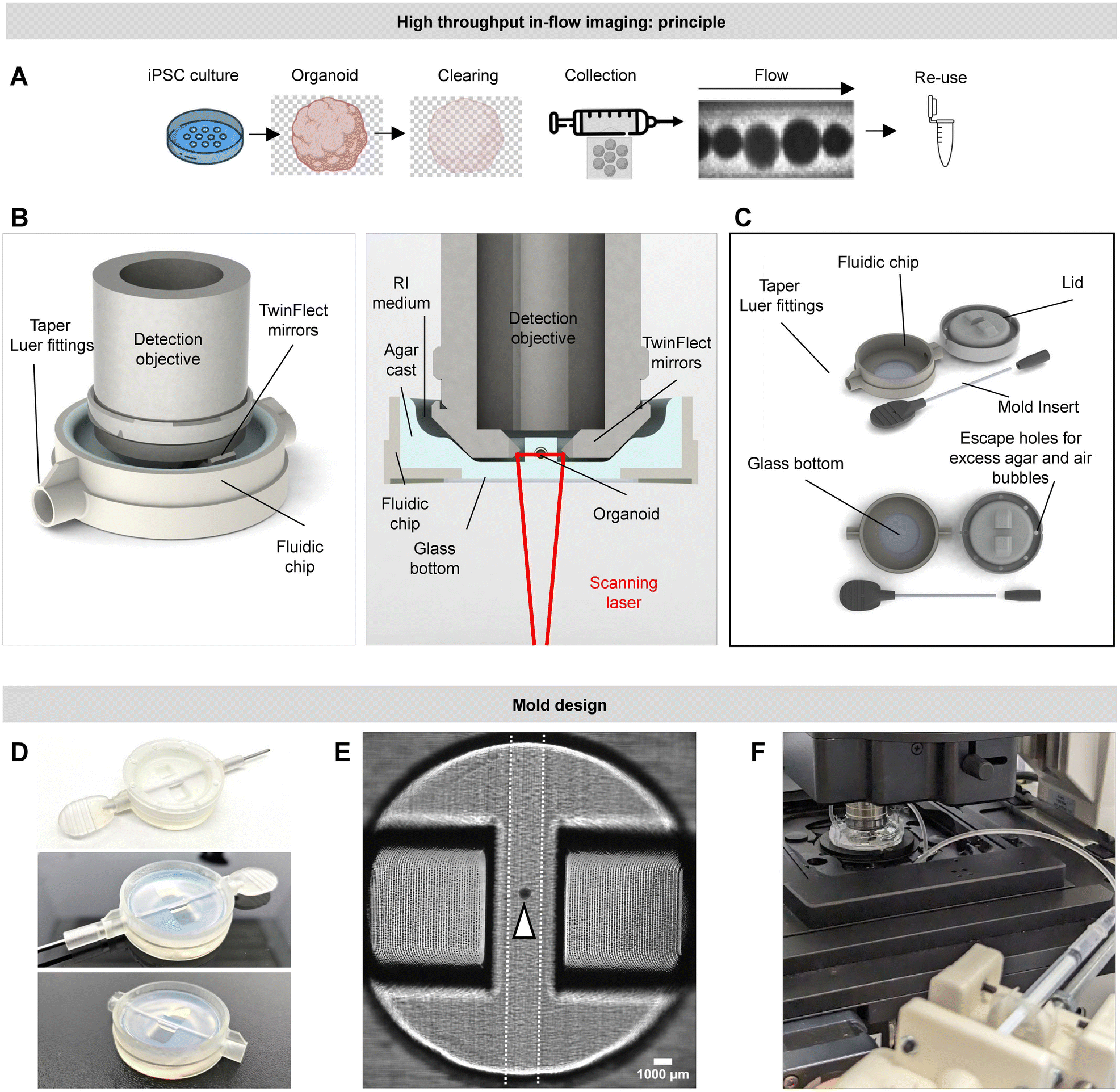 | ||
| Fig. 1 Fluidic chip design and setup principle. (A) Schematic overview of the pipeline for high-throughput light-sheet microscopy using the fluidic chip. After organoid generation and sample preparation (sample clearing and staining), all organoids are placed in suspension in a syringe. By means of a syringe pump, all samples are driven into the fluidic chip while passing through the microscope’s field of view. The outlet of the fluidic chip can be connected to any vessel capturing the samples after imaging to allow repurposing of the organoids. (B) 3D render of the Leica DLS detection objective. The setup is ideal for high-resolution light-sheet imaging of organoid samples up to 1.5 mm in diameter. The fluidic chip is designed to be compatible with the restrictions imposed by this setup. (C) Fluidic chip design. (D) Image of the casting and curing process. The needle is placed into the chip using the dedicated taper Luer connectors. A heated solution of 1% agarose is poured into the chip before sealing the chip with the lid for curing. After a curing period of 20 minutes, the lid and needle can be removed from the chip. Depending on the desired refractive index during imaging, the chip can be filled with imaging medium 12 h prior to imaging to ensure complete RI matching and optimal image quality. The in- and outlet can be attached easily to the chip using the dedicated taper Luer connections at the sides of the chip. (E) Brightfield image (10×, tilescan) giving an overview of the fluidic chip with an organoid placed in the center of the flow channel. (F) Image of the fluidic chip and syringe pump on the microscope stage. | ||
The design incorporates numerous features aimed at optimizing optical clarity and precision within the experimental setup. It includes a glass bottom to ensure optical imaging quality. It also features a cutout, situated to reside just 1 mm above the bottom of a Petridish. This positioning minimizes interference with the light path. The mold's design is optimized so that the resulting cast has parallel side walls surrounding the internal channel, perpendicular to the bottom and top of the chip. This arrangement minimizes light scattering and absorption of the laser during imaging, a potential issue when dealing with RI mismatch between the agarose mold and the immersion liquid. A flat surface atop the channel aids in reducing potential light scattering or reflection that could negatively impact the optical system. This design ensures a more focused light path towards the optics, thereby enhancing the quality of captured images. The internal diameter of the channel, formed by a stainless-steel rod, is adjustable, catering to user requirements in other applications. For this application, it measures 1.60 mm.
Acknowledging the inherent fragility of the 1% agarose cast, specific design adjustments have been employed to reinforce the structure. The housing's rigid body features two female Luer-slip connectors on opposing sides, facilitating seamless connection to the internal channel of the chip. These connectors allow for the insertion of catheters with male Luer-slip connections, resulting in a robust and reliable connection that does not compromise the agarose mold structure. These inlet and outlet connections, referred to as the chip-to-world interface (CWI), enable the chip to be efficiently coupled to a syringe pump and output catheter. Using a low-concentration agarose mixture enhances the degassing process during casting, thanks to its reduced viscosity. This effectively minimizes the formation of air bubbles that could disrupt the internal channel structure or impair imaging clarity. Additionally, the lower concentration of agarose improves RI matching for water-based media.
The fluidic chip used for this research is tailored to accommodate the digitally scanned light sheet module of the Leica SP8 microscope (DLS), but can be adapted to accomodate alternative microscope setups.
Once the printed part is prepared, a 24 × 24 mm glass cover slip (VWR, 631-0127) is attached to the bottom by applying a 2-part epoxy adhesive around the open bottom. After the epoxy has cured for at least 24 hours, this component is ready for use.
The internal volume component is created by attaching a 3D-printed handle to a 1.60 mm stainless steel rod using epoxy resin. This handle features a Luer-slip shaped plug, used to create a tight sealing fit when inserting the mold insert into the main housing of the chip mold. The stainless-steel shaft for this prototype is fabricated from stainless steel welding rods. This not only provides accuracy and robustness but is also believed to contribute to enhanced imaging quality by providing an accurate and polished casting surface, superior to any surface roughness achievable through 3D printing. The design's modularity allows for the adjustment of the internal channel diameter by changing the dimensions of the holes in the plugs to accommodate various diameters of stainless-steel rod.
A male Luer-slip connection-shaped plug is also 3D-printed. This part slides over the stainless-steel shaft, effectively sealing the CWI during casting (Fig. 1D).
The final component, a 3D-printed lid, is required during the molding of the agarose. This lid secures all necessary features that will subsequently be transferred to the agarose cast (Fig. 1D).
The agarose casting is performed in a dust-free environment (e.g., a laminar flow cabinet). The process begins by sealing the CWI using the mold insert on one side of the mold housing and sliding the plug over the stainless-steel shaft to cover the opposite side of the CWI. With the mold now watertight, casting can commence. A 1% Ultrapure Agarose solution (ThermoFisher, 16500500) is prepared in ddH2O and poured into the mold while still warm (approximately 90 °C). After ensuring absence of air bubbles, the lid is immediately placed on top of the mold housing. The lid's design, featuring holes, allows excess agarose to escape and potential air bubbles to rise and exit the mold.
Upon cooling (approx. 20 min at 4 °C), the agarose solidifies, and the plug and stainless-steel mold insert can be removed. The lid is then easily detached, and the hybrid chip is ready for use. The resulting cast aligns precisely with Leica DLS SP8 setup used for validation. Prior to use, the chip is stored in a refrigerated and humidified chamber. To ensure optimal image quality, the agarose cast should be immersed overnight in the appropriate imaging solution for RI matching.
Flow setup
The flow setup consists of (1) a syringe containing all organoid samples, (2) a syringe pump, (3) Arduino-Uno control unit for the pump action, (4) inlet and outlet catheters towards and from the fluidic chip, and (5) the chip itself. The organoid samples are introduced from the syringe into the inlet catheter. The density of the RI medium (solution within the syringe in which the organoids are suspended), horizontal positioning of the syringe pump and number of organoids within the syringe, play an important role in feeding isolated samples into the inlet catheter and ensuring isolated samples within the FOV.For precise control, a high-precision syringe pump is employed, constructed with a NEMA17 stepper motor and a 2 mm pitch leadscrew. This pump connects to the Luer connector of a syringe filled with organoid samples, enabling their delivery into the agarose imaging cast. A custom flow control unit, incorporating an Arduino UNO and a DRV8825 motor driver, facilitates precise, adjustable linear movements. The motor's 1.8° step angle, combined with microstepping capabilities, allows for movements as small as 1/32th of a step. Considering the 2 mm pitch, this setup achieves 3.125 μm linear movements steps. A full 80 mm syringe draw corresponds to 1000 μl, with each micro-step displacing 3.9 nl (nanoliters). A catheter featuring a male and female Luer slip on each side, is used to connect the syringe in the syringe pump with the fluidic chip. The use of smaller syringes and high-accuracy linear movement components can further improve this precision if necessary.
The flow controller includes a logarithmic rotary potentiometer for intuitive speed control, featuring a neutral position that locks the motor. Rotating clockwise induces forward movement, and rotating counterclockwise induces reverse movement. This functionality allows for bidirectional movement of the samples in flow. The distance of the position rotary potentiometer from the neutral point determines the speed, enabling precise control over the feeding and positioning of organoids within the setup.
Theoretical flow behavior
The nature of the fluidic chip implies the samples are in flow during imaging. The dimensions of the organoid samples (and consequently the inner channel diameter of the fluidic chip) are relatively large, ranging between 500 and 1500 μm in diameter. Laminar flow guarantees sample stability and precise control. The Reynolds number, calculated using the formula:where ρ is the fluid density, v the flow velocity, d the diameter of the tube, and μ the dynamic viscosity, provides insight into the flow regime. The mixture currently employed in the flow experiments comprises the following components: 13 mL of double-distilled water (ddH2O), which is equivalent to 13 g, assuming a water density of approximately 1 g mL−1; 24 g of Nycodenz®; and 0.5 g of N-methyl-D-glucamine. This results in a total mass for the mixture of 37.5 g, as detailed in Table 2.

For this mixture, flowing through a tube with a diameter of 1.6 mm at a velocity of 1 mm s−1 (0.001 m s−1), and using a viscosity of 1.60 mPa s (0.00058 Pa s) at 20 °C, the Reynolds number is approximately 1.10. For a higher velocity of 5 mm s−1 (0.005 m s−1), the Reynolds number is approximately 5.50. Both values are well below the threshold of 2000, indicative of highly laminar flow, which is favourable for maintaining sample stability and image clarity. Pressure delays, temperature changes, noise in the motor's movement, obstructions, inconsistent roughness and other variables can also influence the stability of the sample in flow.
Cell and organoid culture
T98G glioblastoma cells (kindly provided by Dr. Nicolas Goffart, University of Liège) and 1321N1 astrocytoma cells (wild type, WT and LMNA knockout, KO) cells (original source ECACC 86030402, single colonies selected after mock-treatment or knockout). Subculturing was performed upon 90% confluency using 0.25% Trypsin–EDTA (Thermo Fisher Scientific, 25200072). 3D spheroids were obtained by subsequently plating the cells in U-bottom 96-well plate (VWR, 734-2782) treated with anti-adherence rinsing solution (Stemcell Technologies, 07010) for 10 minutes at room temperature (RT). The plate was centrifuged directly after cell seeding (2 min at 100 RPM). Spheroid size was varied by adjusting seeding density from 1000 to 10![[thin space (1/6-em)]](https://www.rsc.org/images/entities/char_2009.gif) 000 cells per well. After 72 h of incubation, spheroids were fixed using 4% PFA (Roth, 3105.2) overnight. Before proceeding to tissue clearing, samples were washed 3× with phosphate-buffered saline (PBS).
000 cells per well. After 72 h of incubation, spheroids were fixed using 4% PFA (Roth, 3105.2) overnight. Before proceeding to tissue clearing, samples were washed 3× with phosphate-buffered saline (PBS).
Microglia-populated cerebral organoids were generated from one and the same parental iPSC line (Sigma Aldrich, iPSC0028 Epithelial-1). iPSCs were cultured on Matrigel (Corning, 734-1440) coated plates in Essential 8 medium (Gibco, A1517001). ReLeSR (Stemcell Technologies, 05872) was used for the subculturing of cells. iPSCs were differentiated into neural progenitor cells (NPCs) by splitting them with TrypLE Express Enzyme (Life technologies, 12605010). Cells were seeded at a density of 104 cells per cm in mTesR1 medium (Stemcell Technologies, 85850) supplemented with Rock inhibitor (Y-27632 dichloride, MedChem, HY-10583). For 11 consecutive days, daily medium changes were performed with neural maintenance medium supplemented with 1 μM LDN-193189 (Miltenyi, 130-106-540), SB431542 (Tocris, 1614). Neural maintenance medium consisted of 1:1 Neurobasal (Life technologies, 21103049): DMEM-F12 + Glutamax (Gibco, 10565018), 0.5× Glutamax (Gibco, 35-050-061), 0.5× MEM non essential amino acids solution (Gibco, 11140050), 0.5× sodium pyruvate (Gibco, 11360070), 50 μM 2-mercaptoethanol (Gibco, 31350010), 0.025% human insulin solution (Sigma Aldrich, I9278), 0.5× N2 (Gibco, 17502048), 0.5× B27 (Gibco, 17504044), 50 U ml−1 penicillin–streptomycin (Gibco, 15140122). At day 12 post differentiation, the cells were split using TrypLE Express Enzyme ((Life technologies, 12605010) and allowed to mature further for 20 days until the formation of cerebral organoids in neural maintenance medium using U-bottom 96-well plate (VWR, 734-2782) treated with anti-adherence rinsing solution (Stemcell Technologies, 07010) as described above.
The iPSC parental line was in parallel differentiated into microglial precursors according to a published protocol.13 In short, embryoid bodies (EBs) were formed by seeding 1000 iPSC per well in a low-attachment coated U-bottom 96-well plate. For 4 consecutive days, EBs received mTeSR medium supplemented with Rock inhibitor, 50 ng mL−1 BMP4 (Peprotech, 120-05), 50 ng mL−1 VEGF (Peprotech, 100-20), 20 ng mL−1 SCF (Peprotech, 250-03). EBs were then transferred into a 6-well plate in macrophage precursor medium consisting of X-vivo15 (Lonza, BE02-060Q), 100 ng mL−1 M-CSF (Peprotech, 300-25), 25 ng mL−1 IL-3 (Peprotech, 213-13), 1× Glutamax, 50 U ml−1 penicillin–streptomycin and 50 μM 2-mercaptoethanol. 14 days after the start of macrophage induction, microglial precursors were harvested using a cell strainer (Stemcell technologies, 27250). They were seeded at a density of 10000 cells per organoid 14 days after organoid formation. Organoids were kept in culture for 30 more days after microglia seeding. They were kept in neural maintenance medium supplemented with 100 ng mL−1 M-CSF (Peprotech, 300-25), 100 ng mL−1 IL-34 (Peprotech, 200-34). Medium was changed twice weekly. The organoids were fixed overnight using 4% PFA (Roth, 3105.2) 75 days after the start of neural differentiation.
Tissue clearing, immunocytochemistry and nuclear counterstaining
Organoids were rendered optically transparent for light sheet imaging using Fast3D Clear14 or iDISCO.15,16 For Fast3D Clear, samples were transferred to a 15 ml conical tube (Starstedt, 62.554.502). A dehydration series was performed using tetrahydrofuran (THF) + BHT (Sigma-Aldrich, 360589-1L). PBS was removed from the conical tube and replaced with 50% THF solution. After 1 h incubation at RT while shaking, the 50% solution was replaced by 70% TFH. A second incubation step of 1 h at RT is followed. 70% THF was removed and replaced by 90% THF solution. This was left to incubate while shaking overnight. The following day, rehydration was performed by decreasing the THF concentration to 70% and 50%, each with an incubation time of 1 h. After rehydration was complete, samples were washed 3 × 30 min with PBS while shaking.If required, immunostaining was performed after rehydration by first permeabilizing the samples 8 h at 37 °C in permeabilization solution (for 100 ml in PBS-/-: 200 μl Triton X-100, 2.8 g Glycine, 25 ml DMSO). Samples were then transferred to blocking solution overnight at 37 °C (for 100 ml in PBS-/-: 200 μl Triton X-100, 6 ml serum, 20 ml DMSO). Samples were washed 15 minutes in PTwH (for 100 ml in PBS-/-: 200 μl Tween, 100 μl heparin). Samples were then incubated for 3 days with primary antibody in staining solution (for 100 ml in PBS-/-: 200 μl Tween, 100 μl heparin, 5 ml DMSO, 3 ml serum). After incubation, samples were washed again in PTwH before being transferred to staining solution with secondary antibodies for 2 days. The antibodies used for this manuscript are listed in Table 1.
| Antibody | Host | Supplier | Catalog # | |
|---|---|---|---|---|
| Primary antibodies | Anti-Iba1 | Rabbit | Wako | 019-19741 |
| Anti-gamma H2A.X (phospho S139) antibody – ChIP grade | Mouse | Abcam | ab2893 | |
| Secondary antibodies | Donkey-anti-rabbit-fab-Cy3 | Donkey | Jackson ImmunoResearch | 711-167-003 |
| Goat-anti-mouse-Cy3 | Goat | Jackson ImmunoResearch | 115-165-146 | |
Nuclear counterstaining was performed using NucRed Dead 647 (Thermo Fisher Scientific, R37113) (1 drop per ml, overnight). After staining, the samples were washed 3 × 5 min in PBS and incubated in RI matching medium (which rendered the samples completely transparent) for a minimum of 3 h prior to imaging. All solutions are listed in Table 2.
| Solution | Products | Volume (for 40 ml) | Supplier | Catalog number |
|---|---|---|---|---|
| 50% TFH | THF | 20 ml | Sigma-Aldrich | 186562 |
| ddH2O | 20 ml | |||
| Triethylamine | 40 μl | Sigma-Aldrich | T0886 | |
| 70% THF | THF | 28 ml | Sigma-Aldrich | 186562 |
| ddH2O | 12 ml | T0886 | ||
| Triethylamine | 60 μl | Sigma-Aldrich | ||
| 90% THF | THF | 36 ml | Sigma-Aldrich | 186562 |
| ddH2O | 4 ml | |||
| Triethylamine | 60 μl | Sigma-Aldrich | T0886 | |
| RI medium | ddH2O | 13 ml | ||
| Nycodenz | 24 g | ProteoGenix SAS | 1002424 | |
| Methyl D-glucamine | 0.5 g | Sigma-Aldrich | D9268 |
For iDISCO clearing, samples were stained first using NucRed Dead 647 (Thermo Fisher Scientific, R37113) (1 drop per ml, overnight) prior to dehydration. A dehydration series using methanol was performed using increasing methanol concentration starting at 20%, going to 40%, 60%, 80% and 100% methanol. Each step took 1 h at RT. The samples were then transferred to 66% DCM/33% methanol for 3 h at RT, before the final step of 30 minutes 100% DCM. After clearing, samples were transferred to DBE for RI matching. The agarose fluidic chip received the same treatment to obtain a matching RI for imaging.
Microscopy
To validate the fluidic chip, we quantified the sample positioning speed, sample stability and LSM image quality. Positioning speed and sample stability were quantified using transmission microscopy. Images were acquired using a Nikon Ti2 microscope body with dry 4× objective (NA 0.1, 3.4 μm optical resolution) on a Nikon DS-Qi2 camera (1.8 × 1.8 μm spatial resolution).LSM images were acquired with a Leica TCS SP8 digitally scanned light sheet (DLS) microscope. A 2.5× illumination objective (fluostar, NA 0.07, cat. nr. 506523) was used in combination with 5 mm TwinFlect mirrors (cat. nr. 158007011) and 10× detection objective (APO NA 0.30, cat. nr. 506524). Images were acquired at a voxel size (X, Y, Z) of 0.3594 × 0.3594 × 3.7 μm3. A white light laser with AOBS (acousto-optical beam splitter) was used to obtain an excitation wavelength of 638 nm in combination with a 638 nm notch filter at the emission site to visualize the nuclei counterstained with NucRed Dead 647. Both left and right mirrors were used during imaging and both sides were automatically merged by the LAS X software.
Single plane illumination images (cylindrical lens based) were acquired with the Lavision Biotec Ultramicrosocpe II (Miltenyi) using right-sided triple light sheet illumination using the 5× or 6.3× magnification at a resolution of respectively 0.6 and 0.45 μm2 per pixel and NA of 0.5. A Z-sample size of 4 μm was used.
Image analysis
For automation and smart flow control using the NIS-elements software, NanoJ-Fluidics17 hardware and software was used to integrate Arduino-Uno driven pump control with on-the-fly image evaluation. All spheroid samples were placed into a U-bottom 96-well plate. By placing the free end of the fluidic chip catheter in the multi-well plate and moving sequentially from well-to-well, consecutive samples were drawn into the fluidic chip towards the syringe. The Arduino-Uno with motor shield received input from the NIS-elements software and drove the syringe pump. The NIS-elements software evaluated the FOV (by calculating the standard deviation) with a frame rate of 2 frames per second and upon reaching the threshold, triggered both the Arduino-Uno to stop the pump and the microscope to start the image acquisition sequence. Upon image completion, the NIS-elements software again triggered the Arduino-Uno to start the pump, repeating the steps above (Fig. 3A). As detection criterion, we measured the standard deviation of the intensity across the FOV with a threshold of 600 as trigger for stopping the flow (Fig. 3C). A delay time of 10 seconds before initiating the acquisition was included to allow the spheroid to halt. A delay time of 6 seconds after image completion was included to allow the spheroid to move out of the FOV.
Post hoc spheroid detection from the recorded images was performed using OpenCV (reading video feed and detecting objects) and Numpy (drawing circles around detected objects in output video) packages in Python software. Circular objects were detected using the SimpleBlobDetector class in OpenCV according to the following parameters: threshold: (>1; <200), area: (>20000; <120000), circularity: (>0.3), convexity: (<0.1) (Fig. 2C). Sample movement during passage through the FOV was quantified as the deviation of the sample centroid from the mean centroid position for each sample (Fig. 2D).
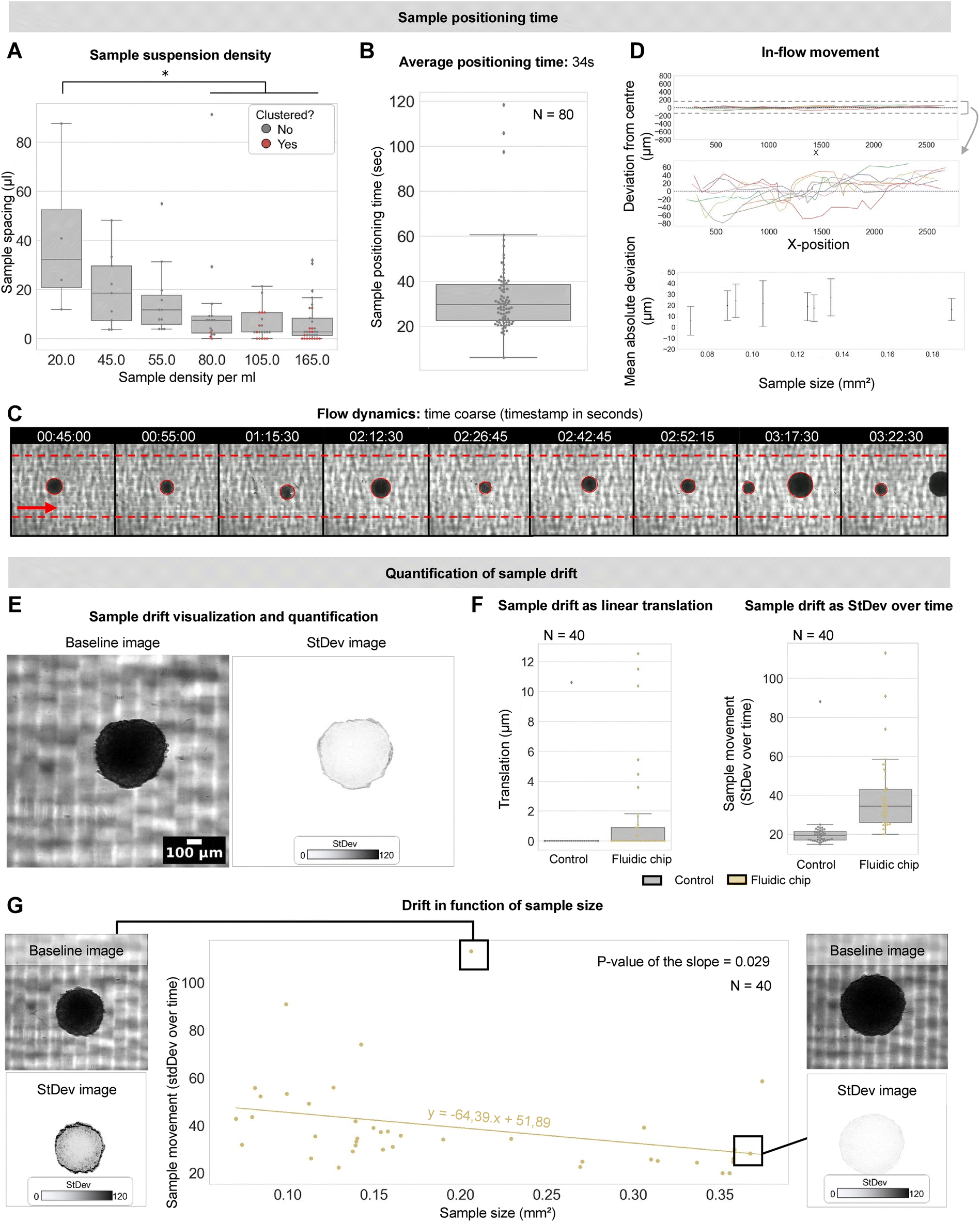 | ||
| Fig. 2 Validation of throughput capacity, flow stability and compatibility with varying sample size. (A) The spacing between individual samples as they pass through the fluidic chip for different sample densities. Red dots are clustered samples. (B) Time required to position each sample into the field of view for a density of 50 spheroids per ml. Dots represent individual samples. (C) Montage of widefield recording of spheroids flowing through the fluidic chip including timestamp and automated detection (red circle). Red arrow indicates the flow direction. (D) Deviation of the sample centroid coordinates from the center during passage through the fluidic chip. Top figure shows y-axis scaled to the total internal channel diameter. Middle figure is zoomed to the maximal observed drift. Bottom figure is mean absolute deviation of samples moving through the field of view in function of sample size. (E) Visualization of sample drift during a 1-minute widefield recording. The standard deviation projection over all timeframes represents the intensity of sample movement (translation and rotation) in a quantifiable manner. (F) Sample drift quantified as linear translation and standard deviation projection over time. Dots represent individual spheroids. (G) Sample drift (measured as standard deviation over time) in function of sample size alongside example images. Dots represent individual spheroids. | ||
Sample drift was determined during a 1 minute recording (frame rate of 2 fps) (Fig. 2E). Sample movement during imaging was quantified as the linear translation of its centroid and as the standard deviation of the intensity values within the projected sample region of interest (ROI) across all timeframes (Fig. 2F). We opted for the latter readout for drift quantification as it encapsulates both translational as rotational movement, which is not the case for simple linear distance measurements. Analysis was performed using FIJI, image analysis freeware.18
Image quality was measured in the XY-plane as well as across the Z-axis. Metrics for image contrast and resolution were determined on the original image and image derivative, respectively. Quantification of all parameters was performed in well-defined ROIs (5% of total image size). Each ROI constituted an inset at the same location within each image of distinct spheroids and mounting methods. Within each ROI, the dynamic range was determined as the maximal intensity subtracted from the minimal intensity divided by the mean intensity value and the coefficient of variation (CoV) as the standard deviation value divided by the mean intensity value (Fig. 4A).
Nuclear segmentation was performed on single optical slices of the in toto image stack (Fig. 7A). Preprocessing was performed using Gaussian Blur with a radius of 5 pixels. Maxima were detected using a prominence of 20 after which single points with tolerance (binary image) could be generated. ROIs were detected and enlarged by 3 pixels, yielding a robust 2D detection of nuclei from the in toto spheroid image using Fiji.18 For each consecutive optical z-slice, nuclear segmentation was performed which resulted in single-nuclei feature information (e.g., area, average fluorescence intensity) associated with the 3-dimensional location of each nucleus. Further, Napari19 was used to create 3D renders of in toto images.
Results
A fluidic chip allows rapid sequential positioning of individual spheroids in the field of view
We designed a chip for efficient imaging of spheroids in flow. T98G spheroids in PBS were transferred into a syringe and a pump was manually controlled to gently flow the solution through the connected tubing and position the spheroids in the field of view (FOV). To benchmark its performance, we first defined the optimal number of samples that could be imaged within a fixed timeframe without causing overt clustering. To this end, we tested a concentration range of 20-165 glioblastoma spheroids per ml (in the syringe) with sizes in between 0.004 and 0.180 mm3. Using a flow rate of 1 mm s−1 inside the imaging channel, we measured the spacing between consecutive samples and their clustering in the FOV. Increasing the sample density from 20 to 80 spheroids per ml significantly decreased sample spacing resulting in a faster sample transit. However, at a density of 80 samples per ml, several spheroids displayed clustering, which became even more pronounced for higher densities. We therefore opted for a density of 50 spheroids per ml for further experiments (Fig. 2A). At this density, we found that consecutive positioning of isolated spheroids could be achieved with an average time interval of 34 ± 18 seconds (Fig. 2B, ESI† Movie S1), thus resulting in an estimated throughput of approximately 40 LSM recordings per hour (given an image acquisition time of 1 minute). For comparison, classical mounting techniques where spheroids are fixed in agarose are in the time range of 15 minutes per sample.12 Our approach thus constitutes a 35-fold improvement over manual sample handling.Samples in flow retain their positional stability within the acquisition time window
Having defined an optimal sample density, we next quantified the stability with which individual T89G glioblastoma spheroids move through and can be positioned in the FOV. We implemented an automated sample detection algorithm to identify and track the samples as they enter and move across the FOV (Fig. 2C). We first quantified the off-axis displacement (i.e., perpendicular to the flow) of individual spheroids along their trajectory in flow (at a flow rate of 1 mm s−1 and with an acquisition rate of 4 fps). Although calculations of the Reynolds number indicated a laminar flow (R = 1.10–5.5), we noted fluctuations within a range of −70 to +70 μm around the central axis (1/11th of the internal channel's diameter) during movement (Fig. 2D). This was independent of the sample size (Fig. 2D) and is likely due to subtle obstructions and cell debris in the channel. However, this need not be problematic as the 3D imaging is not performed in flow but when samples are halted at one position. Hence, we next measured the stability of the samples in the FOV when the fluid flow is arrested. We acquired a series of 40 spheroids of the same size range using timelapse brightfield microscopy. To emulate a realistic LSM acquisition sequence, each temporarily halted spheroid was acquired for 1 minute at 2 fps. We quantified the translation of the spheroid barycentre as well as the standard deviation of the signal intensity of the projected area of the sample (a metric sensitive to both linear and rotational components) as reporters for spheroid movement across time (see M&M) (Fig. 2F). The control condition consisted of same-sized (±0.18 mm3) spheroids placed in a U-bottom 96-well plate. This revealed that 32 samples (80%) showed submicron linear movement (translation). Both translation and standard deviation, showed significantly more drift in the samples mounted using the fluidic chip in comparison to the control condition. However, the actual displacement in X and Y was limited to a max. of 12.6 μm (3.7× the optical resolution) and the motion inaccuracy mainly pertained to smaller samples (as indicated by the significant negative correlation (slope = −64.39, p-value of the slope: 0.029) between the measured standard deviation and sample size, Fig. 2G).Sample positioning can be automated through intelligent image-based feedback control
In the initial implementation, an operator manually controls the speed rate to position the sample and start the image acquisition sequence. To automate this process, we introduced an online recognition module that steers the Arduino-controlled syringe pump based on the image content (Fig. 3A). As a proof of principle, we ran an automated sequence to record 45 T98G spheroids in brightfield mode (Fig. 3B). Of the captured images, 82% (N = 37) contained correctly positioned spheroids the samples were imaged correctly, 3 contained clustered samples, 3 were empty and 2 contained spheroids at the edge of the FOV (Fig. 3B). We found that the time required to position a sample in the FOV was 24 ± 5 seconds. Although not significantly different from the manual positioning speed, this illustrates that image-based flow control enables sample positioning at least as fast, but without the requirement of an operator (Fig. 3D and E). | ||
| Fig. 3 Automatic sample positioning. (A) Schematic overview and images of the automated sample positioning setup. The microscope software evaluates the FOV for the presence of a spheroid. Upon sample recognition, the software communicates to the Arduino-Uno driving the syringe pump to stop the flow which holds the sample in position. After completion of image acquisition, the microscope software instructs the Arduino-uno to again start the syringe pump. Samples are withdrawn from a multiwell plate. (B) Brightfield images of spheroids automatically positioned in the FOV. The timestamp indicates the time interval between the respective ends of the previous and next image. Red arrow indicates the flow direction. The red box highlights samples that were not optimally positioned. (C) Intensity standard deviation across the full FOV over time. Upon reaching the threshold, the Arduino-Uno is triggered to stop the sample flow and the microscope software will start the image acquisition sequence. The red line indicates the threshold. (D) Time interval between successive spheroids to be positioned in the FOV. The sample positioning time for manual positioning and automated flow control are compared. (E) Automatic positioning time for individual samples. | ||
Optical quality of in flow imaging is on par with fixed agarose mounting
The image quality of LSM is mainly defined by the sample stability and the refractive index (RI) of the material and the immersion medium (for FAST3D Clear, the RI of the imaging solution is 1.512–1.515) (Table 3). Hence, the current standard for mounting small organoid samples for LSM is to fix them in an agarose block. Other approaches include mounting in glass capillaries or fluorinated ethylene propylene (FEP) tubes. To obtain a view on the image quality, we compared these methods to our fluidic chip cast in either 1% agarose or polydimethylsiloxane (PDMS), a commonly used casting material for optically transparent chips.| Mounting method | Refractive index (RI) |
|---|---|
| Fixed in 2% agarose | Depending on the imaging medium |
| PDMS fluidic chip | 1.42 |
| FEP tube | 1.34 |
| Glass capillary | 1.52 |
| 1% agarose fluidic chip | Depending on the imaging medium |
A visual assessment revealed the best image quality using agarose-based mounting methods, closely followed by glass. In contrast, FEP and PDMS mounting methods resulted in blurry images (Fig. 4A). To quantify the image quality, we plotted the mean intensity across a line through the XY-plane and determined the dynamic range and coefficient of variation (CoV) for randomly selected ROIs across the sample. For each mounting type, measurements were performed in the exact same ROIs, as the image quality depends on the distance to the light sheet and to the detector (Fig. 4A).
 | ||
| Fig. 4 Validation of light-sheet image quality across different sample mounting modalities. (A) Center slices (350 μm depth) from LSM image stacks in the xy-plane for each sample mounting modality. Insets originate from the same location in each of the larger images. An XY lineplot across every inset is shown (at the location of the dotted line). An XZ lineplot across the entire depth of the spheroid is shown. XY-image contrast quantification is performed by calculating the dynamic range and coefficient of variation for 10 insets across the image. Resolution is quantified using the image derivative in XY and Z axes. (B) 3D renders of spheroids imaged fixed in agarose vs. using the fluidic chip. | ||
The PDMS holder performed significantly poorer as compared to all other mounting approaches (p = 0.37 × 10−0.5). Quantification revealed performance of the fluidic chip similar to glass and fixed agarose mounting procedures.12,20 FEP tubes and PDMS casts characterized by their lower RI, show much lower values for both image contrast metrics.12,21 For all mounting modalities, image quality degraded with sample depth (increasing distance to the detection objective). However, there was no significant intensity decay for any of the sample mounting modalities, rather a loss of resolution as evidenced by the degrading mean intensity of the derivative image across the z-axis (Fig. 4A). A direct comparison of two 3D rendered images, one fixed in agarose and one visualized using the fluidic chip, strengthened our conclusion that the image quality in the fluidic chip is on par with the current state-of-the-art mounting strategy (Fig. 4B). To further explore the image quality, we switched to a sample with high preclinical potential, namely microglia-infiltrated cerebral organoids. Using immunofluorescence staining for the canonical glial marker IBA1, we confirmed the presence of microglia throughout the full depth of the cerebral organoid (Fig. 5A and B). Suspended in the flow chamber, the ramifications of individual microglia, proxies of a more homeostatic phenotype, could easily be discerned in 3D, underscoring the high image quality (Fig. 5C).
 | ||
| Fig. 5 In toto visualization of microglia in a populated cerebral organoid. (A) Z-Slices of an in toto organoid populated with microglia and visualized using light-sheet microscopy. Z-Slices are sampled from the total z-stack starting 75 μm from the top and spaced 150 μm apart. (B) Inverted 3D renders and depth-encoded projection of the IBA1-labeled microglia-populated organoid acquired in toto using light-sheet microscopy. (C) Depth-encoded and max-projected inverted insets of microglia of panels A and B. Scale bar is 20 μm. Line profiles highlight the fine resolution obtained using the setup. | ||
The fluidic chip can be tailored to alternative clearing procedures and imaging modalities
The fluidic chip was designed to comply with a specific LSM system but is compatible with any inverted or upright microscope. However, other light sheet systems have side illumination traveling over a larger distance before reaching the sample causing it to scatter when hitting the walls of the dish. To circumvent this issue, we designed a similar fluidic chip with identical dimensions, but without the 3D-printed well support and catheters directly inserted into the agarose cast (Fig. 6A–C). We tested this stripped version of the fluidic chip on a different setup (Lavision Ultramicroscope II), with a different clearing procedure (iDISCO) to assess its versatility (Fig. 6C). In toto images of 0.004 mm3 sized T98G glioblastoma spheroids were acquired using NucRed Dead 647 nuclear counterstain in flow (Fig. 6D). We did notice a smaller sample size and reduced image quality as compared to the FAST3D approach, which is due to the shrinkage that accompanies the classical iDISCO clearing procedure. Nevertheless, individual nuclei could still be discriminated (Fig. 6D–F). | ||
| Fig. 6 Fluidic chip validation using solvent-based clearing on a dedicated light-sheet microscope setup. (A) 3D renders of the adapted mold and agarose cast compatible with the Lavision Ultramicroscope II setup. (B) Images of the agarose-only fluidic chip setup on the Lavision Ultramicroscope II. (C) Schematic overview of the fluidic chip setup on scanned vs. single-plane illumination microscope. The scanned LSM (Leica SP8 DLS), makes use of mirrors placed directly around the spheroid sample and is compatible with water-based clearing methods. The hybrid fluidic chip (Fig. 1) uses a combination of agarose cast and 3D printed support. An alternative agarose cast without 3D printed support was created for compatibility with the Lavision Ultramicroscope II light sheet microscope. The fluidic chips are processed along with the samples according to the clearing protocol of choice (Fast 3D Clear or iDISCO). (D) Images of 2 spheroids cleared with iDISCO and deepred nuclear counterstain. 10 z-slices are shown for each spheroid from top to bottom with increasing z-depth. Images were recorded using 5× (NA 0.5) objective. (E) Inverted 3D renders of spheroids imaged using iDISCO (Ultramicroscope II) and Fast3D Clear (Leica SP8), illustrating the sample shrinkage with the former. (F) Insets of spheroids imaged using the Ultramicroscope II with 6.3× magnification (0.5 NA). Lined in red, the nuclear segmentation is shown. | ||
In flow imaging enables spatially resolved in toto mapping of cell states
Having confirmed that the chip allows single cell resolution, we tested whether we could use it to discriminate dead from live cells in toto. We visualized 3 days old T98G glioblastoma spheroids counterstained with NucRed Dead 647 (Fig. 7 and S1†). Individual nuclei were detected, and basic nuclear features (intensity and area) were used to quantify their state (live/dead) (Fig. 7A). Projecting this information back onto the image allowed visualizing the location and abundance of dead cells in single slices and for unveiling putative necrotic regions (where many dead cells cluster) in the entire 3D volume of the spheroid (Fig. 7A–C). | ||
| Fig. 7 3D single-cell analysis of spheroids and the necrotic core. (A) Inset of a glioblastoma spheroid stained with nuclear counterstain imaged using the fluidic chip on the Leica SP8 DLS microscope. Rudimentary nuclear segmentation on the inset is shown in green. In red, the nuclei labelled as ‘dead’ are highlighted. The live/dead thresholding was performed based on the nuclear fluorescence intensity. Quantification of 8 z-slices throughout the full depth of the spheroid. Slices are selected at z-depths with 100 μm spacing, starting 100 μm from the top of the z-stack. For each slice, live/dead thresholding is performed based on the ROI intensity. The location and size of the live or dead cells are visualized for each slice by color coding the ROIs and plotting their XY-coordinates. (B) Inverted 3D render of the full spheroid with 3D scatterplot of live/dead cells in the full spheroid. (C) Bar chart quantifying live/dead cells per z-slice in panel A. | ||
Building on this experiment, we designed a second use-case to evaluate DNA damage response in spheroids over time. Etoposide was used to elicit DNA damage in two-week-old spheroids of 1321N1 astrocytoma cells (wild type, WT) and their response was compared with that of a stable knockout (KO) colony of the LMNA gene (known to play a role in DNA damage repair22–24) (N = 59 samples). Spheroids were fixed at three time points post-treatment (control, 8 h, 24 h) and immunostained for the DNA double strand break marker γH2AX and counterstained with NucRed Dead 647 (Fig. 8A). For each sample, we calculated the spheroid size (as a proxy for its health condition) and the degree of DNA damage (γH2AX intensity and number of positive cells) (Fig. 8B). Statistical analysis using two-way ANOVA revealed that the treatment had a significant effect on DNA damage with time and a significantly stronger effect in LMNA KO cells, leading to the full loss thereof at 24 h (Fig. 8C). These proof-of-concept results illustrate that the fluidic chip can be used to perform statistically relevant quantitative experiments with organoids at single-cell level and pave the way for high-throughput assays.
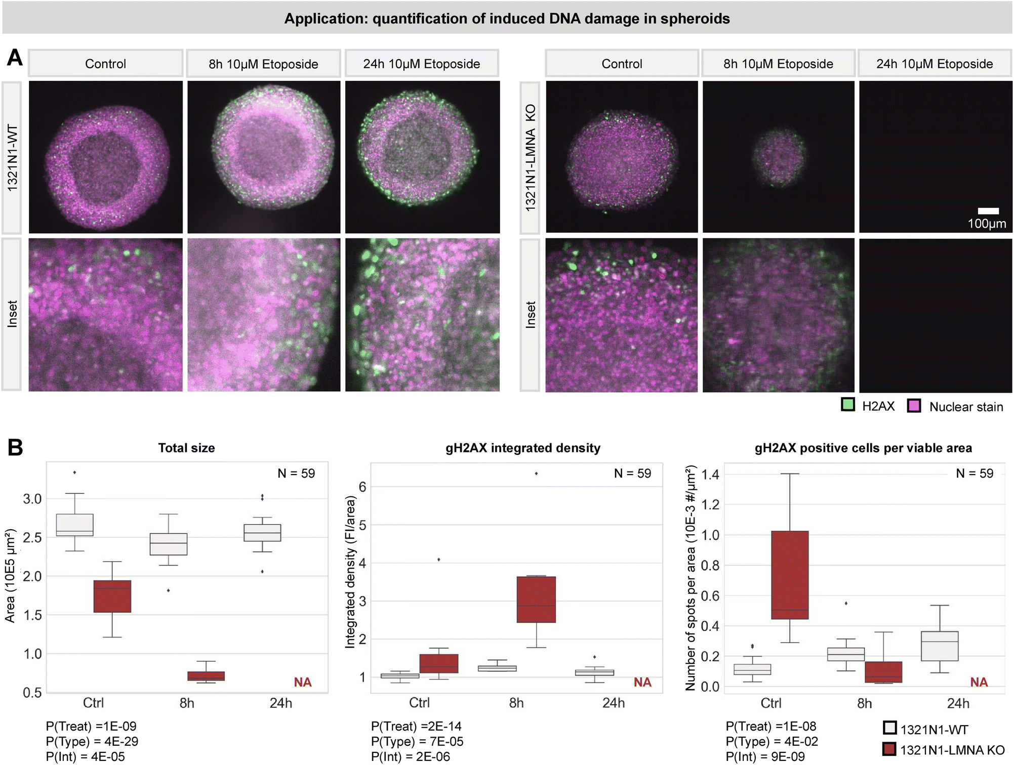 | ||
| Fig. 8 Quantification of induced DNA damage in spheroids. (A) DNA damage was induced in spheroids using 10μM etoposide for 2 timepoints in 2 cell types. gH2AX was used to stain for DNA damage. A number of 8–13 organoids was imaged per condition using our fluidic light-sheet setup. Middle slices are shown from the center of the spheroid. For the LMNA KO condition, the 24 h timepoint caused severe damage resulting in complete loss of all spheroids in this condition. (B) Parameters reflecting the health and DNA damage upon etoposide treatment are measured in all (N = 59) spheroids. Statistical analysis (two-way ANOVA) was performed. P-Values are indicated on the figure. P(Treat) reflects the significance of the etoposide treatment. P(Type) reflects the significance of the cell type (WT vs. LMNA KO). P(Int) reflects the interaction between both. | ||
Discussion
This work introduced a novel approach to organoid imaging by moving away from conventional fixed or arrayed sample methods,11 which are labor-intensive and limited in throughput. The agarose fluidic chip significantly enhanced the speed and efficiency of LSM imaging without requiring modifications of existing LSM setups.12The fluidic chip supports fast sample positioning, with a 35-fold speed increase over manual sample embedding and positioning, as is the current method of choice in many laboratories. Despite, some deviations from the predicted laminar flow, sample movement during transit was limited and did not interfere with positioning stability or image quality during a typical 1-minute LSM imaging period. 80% of the imaged samples showed submicron linear drift, with 7% outliers showing higher disturbances. These effects might be caused by pressure delays induced by the stepwise motion of the syringe pump, temperature fluctuations and larger samples or debris. Debris within the organoid suspension can cause blockages inside the internal volume and disturb or obstruct the flow. More accurate syringe pumps and better motor drivers might make the movement of the flow more consistent and reduce sample movement. Passing the solution through a strainer could contribute to increased purity within the internal fluid. Outliers can be explained by manual handling errors (e.g., impacts or accidental movement of the setup/syringe) and sample size. We found that smaller spheroids were more susceptible to motion artefacts within a channel of fixed size (internal diameter of 1.6 mm), but while we assume lowering the internal channel diameter might resolve this, most future applications will revolve around large mm-sized samples such as cerebral organoids.
To pave the way for further upscaling, we introduced an image-based feedback scheme, in line with the current evolution of smart microscopy systems.25–27 We used this for automating in-flow sample positioning setup and found we could position the samples at a comparable speed as for manual flow control, but without an expert operator. A major advantage of in-flow organoid imaging is the throughput increase over manual or arrayed-sample mounting approaches11 as the number of samples is only limited by the volume of the container (i.e., the syringe) and not by the array size. Our setup made use of an Arduino-driven syringe pump controlled by the microscope software. The rotating action of the syringe pump allows two modes: (1) infusing liquid to position samples contained inside the syringe through the channel into the FOV and (2) withdrawing liquid containing organoids sequentially from a container such as a multi-well plate. This latter approach is ideally suited when multiple conditions need to be screened, whereas the former approach is advantageous when many organoids of a single condition need to be visualized. Although promising, variability in sample quality (clustering) and object recognition introduced inaccuracies in the timing and precision of the feedback loop. A more accurate image recognition based on object detection and optimisation of the lag times before and after the image acquisition sequence are bound to resolve this. The use of the standardized multi-well format as sample carrier makes the setup fully compatible with commercially available plate hotels and associated robotics enabling it to run independent of a manual operator.
The resulting LSM image quality allowed visualizing individual nuclei as shown by the images of glioblastoma spheroids. The chip is based on agarose. Glass capillaries and FEP tubes constitute two other often used possibilities for sample mounting.10,12 As they are non-permeable to the imaging medium used, the resulting image quality highly depends on the immersive liquid used. As for FEP, the RI approaches that of water, making it ideally suited for imaging small uncleared spheroids or zebrafish.10,12 Glass, having an RI of 1.52 can be used in combination with iDISCO15 or ethyl cinnamate clearing28 having respective refractive indices of 1.561 (DBE) and 1.558. Correct combinations of clearing and sample mounting methods are imperative for obtaining optimally resolved images, as supported by our results. Our agarose-based approach removes this constraint as the RI of the gel approximates the RI of the liquid in which it is dissolved or immersed. The permeable properties of hydrogels such as agarose allow liquid exchange, causing the RI to always match the RI of the surrounding liquid closely.29 To prove this, we showed the compatibility of our fluidic chip with both water-based (FAST3D) and organic solvent-based (iDISCO15) clearing.
Another multi-immersion solution for light-sheet microscopy was developed recently using an open-top LSM device.9 This is compatible with a variety of clearing protocols and in combination with an array-type parallel mounting system for increased throughput. In contrast to multi-well approaches,9,11 our approach has unlimited potential for upscaling, has a larger working distance and does not require a specific sample size. And while a fluidic approach has previously been proposed (SPIM-fluid12), our setup integrates the use of a transparent agarose matrix within the fluidic chip, enhancing compatibility with different LSM systems. Similar to SPIM-fluid, it employs systematic control over sample positioning and flow dynamics via a precision syringe pump, driven by an Arduino Uno microcontroller. The Arduino platform makes it amenable to integration with existing microscope software and further automation. We opted to use a horizontal light-sheet configuration in combination with complete sample halting during imaging. This setup reduces motion artefacts, requires no adaptations to the standard LSM and reduces transit time between samples, ultimately increasing sample throughput.
A second advantage is the flexibility to cater for differently sized organoids with a channel of one fixed diameter. The simplicity of the chip design facilitates both mass production opportunities and customization by individual researchers with access to a simple 3D-printer. The design could easily be adapted to HiLo30 or SPIM31 setups by providing openings in the sides of the 3D-printed housing that allows the laser to enter the agarose part of the chip without interference of insufficiently index-matched 3D-printed components, as we performed for compatibility with the LaVision Ultramicroscope II. Furthermore, the system allows for samples to be captured after imaging, which supports subsequent analytical procedures such as detailed morphological studies or genetic analyses. With the foundational automation capabilities already in place, and proof of concept for object detection, there is significant scope for further automation and content-aware feedback. Future improvements could focus on optimizing the flow dynamics and exploring alternative materials that might offer enhanced performance or compatibility with a wider range of imaging conditions. In conclusion, by streamlining the imaging process and reducing the manual labor, the presented approach speeds up complete organoid imaging and improves the reproducibility and reliability of such large-scale experiments. The implications of these advancements are profound, particularly in fields requiring high-throughput screening methods such as drug development, toxicology, and personalized medicine.
Abbreviations
| CoV | Coefficient of variation |
| CWI | Chip-to-world interface |
| FEP | Fluorinated ethylene propylene |
| FOV | Field of view |
| LSM | Light-sheet microscopy |
| PBS | Phosphate buffered saline |
| PDMS | Polydimethylsiloxane |
| RI | Refractive index |
| ROI | Region of interest |
| RT | Room temperature |
| THF | Tetrahydrofuran |
Data availability
The authors report that the results of this study are available within the manuscript and ESI† materials. Videos of 3D images supporting this article have been included in the ESI.†Author contributions
Sarah De Beuckeleer, conceptualization, data curation, formal analysis, resources, investigation, validation, visualization, writing – original draft; Andres Vanhooydonck, conceptualization, resources, software, validation, visualisation, writing – original draft; Winnok De Vos, conceptualization, supervision, budget, writing – original draft, review & editing; Regan Watts, conceptualization, supervision, writing – review & editing; Johanna Van Den Daele, validation; Tim Van De Looverbosch, review & editing; Peter Ponsaerts, supervision, review & editing; Hera Kim, resources, validation; Coen Campsteijn, resources, validation.Conflicts of interest
The authors declare the filing of a patent application regarding the fluidic chip and its use for in toto organoid imaging in flow.Acknowledgements
We would like to thank Sofie Thys for her kind help and expertise in the experiments with the LaVision Ultramicroscope II. We thank David D'Haese for his aid in automating the sample positioning. We thank Jorrit De Waele (University of Antwerp) and Dr. Nicolas Goffart (University of Liège), who kindly provided us the T98G cell line used for the performed experiments. This work was funded by Fonds Wetenschappelijk Onderzoek Vlaanderen (1SB7425N, I000123N, I003420N, 1274822N), the University of Antwerp (41500, 44742, 51986), and VLAIO (HBC.2023.0155).References
- Z. Zhao, X. Chen, A. M. Dowbaj, A. Sljukic, K. Bratlie and L. Lin, et al., Organoids, Nat. Rev. Methods Primers, 2022, 2(1), 94 CrossRef.
- M. A. Lancaster, M. Renner, C. A. Martin, D. Wenzel, L. S. Bicknell and M. E. Hurles, et al. Cerebral organoids model human brain development and microcephaly, Nature, 2013, 501(7467), 373–379 CrossRef.
- K. B. Jensen and M. H. Little, Organoids are not organs: Sources of variation and misinformation in organoid biology, Stem Cell Rep., 2023, 18(6), 1255–1270 CrossRef.
- N. Choo, S. Ramm, J. Luu, J. M. Winter, L. A. Selth and A. R. Dwyer, et al. High-Throughput Imaging Assay for Drug Screening of 3D Prostate Cancer Organoids, SLAS Discovery, 2021, 26(9), 1107–1124 CrossRef PubMed.
- E. Van Breedam, A. Nijak, T. Buyle-Huybrecht, J. Di Stefano, M. Boeren and J. Govaerts, et al. Luminescent Human iPSC-Derived Neurospheroids Enable Modeling of Neurotoxicity After Oxygen–glucose Deprivation, Neurotherapeutics, 2022, 19(2), 550–569 CrossRef PubMed.
- S. J. Yoon, L. S. Elahi, A. M. Paşca, R. M. Marton, A. Gordon and O. Revah, et al. Reliability of human cortical organoid generation, Nat. Methods, 2019, 16(1), 75–78 CrossRef.
- N. Felcher, D. Achiriloaie, B. Lee, R. McGorty and J. Sheung, Design and Building of a Customizable, Single-Objective, Light-Sheet Fluorescence Microscope for the Visualization of Cytoskeleton Networks, J. Visualized Exp., 2024,(203), 65411 Search PubMed.
- M. B. M. Meddens, S. Liu, P. S. Finnegan, T. L. Edwards, C. D. James and K. A. Lidke, Single objective light-sheet microscopy for high-speed whole-cell 3D super-resolution, Biomed. Opt. Express, 2016, 7(6), 2219 CrossRef PubMed.
- A. K. Glaser, N. P. Reder, Y. Chen, C. Yin, L. Wei and S. Kang, et al. Multi-immersion open-top light-sheet microscope for high-throughput imaging of cleared tissues, Nat. Commun., 2019, 10(1), 2781 CrossRef.
- M. Bernardello, E. J. Gualda and P. Loza-Alvarez, Modular multimodal platform for classical and high throughput light sheet microscopy, Sci. Rep., 2022, 12(1), 1969 CrossRef.
- A. Beghin, G. Grenci, G. Sahni, S. Guo, H. Rajendiran and T. Delaire, et al. Automated high-speed 3D imaging of organoid cultures with multi-scale phenotypic quantification, Nat. Methods, 2022, 19(7), 881–892 CrossRef.
- E. J. Gualda, H. Pereira, T. Vale, M. F. Estrada, C. Brito and N. Moreno, SPIM-fluid: open source light-sheet based platform for high-throughput imaging, Biomed. Opt. Express, 2015, 6(11), 4447 CrossRef PubMed.
- W. Haenseler, S. N. Sansom, J. Buchrieser, S. E. Newey, C. S. Moore and F. J. Nicholls, et al. A Highly Efficient Human Pluripotent Stem Cell Microglia Model Displays a Neuronal-Co-culture-Specific Expression Profile and Inflammatory Response, Stem Cell Rep., 2017, 8(6), 1727–1742 CrossRef.
- S. Kosmidis, A. Negrean, A. Dranovsky, A. Losonczy and E. R. Kandel, A fast, aqueous, reversible three-day tissue clearing method for adult and embryonic mouse brain and whole body, Cells Rep. Methods, 2021, 1(7), 100090 CrossRef.
- N. Renier, Z. Wu, D. J. Simon, J. Yang, P. Ariel and M. Tessier-Lavigne, iDISCO: A Simple, Rapid Method to Immunolabel Large Tissue Samples for Volume Imaging, Cell, 2014, 159(4), 896–910 CrossRef PubMed.
- G. Lio, A. Soumier, C. Demily and A. Sirigu, An optimized iDISCO+ protocol for tissue clearing and 3D analysis of oxytocin and vasopressin cell network in the developing mouse brain, STAR Protoc., 2023 DOI:10.1016/j.xpro.2022.101968 , 36598854.
- P. Almada, P. M. Pereira, S. Culley, G. Caillol, F. Boroni-Rueda and C. L. Dix, et al. Automating multimodal microscopy with NanoJ-Fluidics, Nat. Commun., 2019, 10(1), 1223 CrossRef PubMed.
- J. Schindelin, I. Arganda-Carreras, E. Frise, V. Kaynig, M. Longair and T. Pietzsch, et al. Fiji: an open-source platform for biological-image analysis, Nat. Methods, 2012, 9(7), 676–682 CrossRef PubMed.
- C. L. Chiu and N. Clack, The napari community. Napari: A Python Multi-Dimensional Image Viewer Platform for the Research Community, Microsc. Microanal., 2022, 28(S1), 1576–1577 CrossRef.
- T. Bruns, S. Schickinger, R. Wittig and H. Schneckenburger, Preparation strategy and illumination of three-dimensional cell cultures in light sheet–based fluorescence microscopy, J. Biomed. Opt., 2012, 17(10), 1015181 CrossRef PubMed.
- A. Mata, A. J. Fleischman and S. Roy, Characterization of Polydimethylsiloxane (PDMS) Properties for Biomedical Micro/Nanosystems, Biomed. Microdevices, 2005, 7(4), 281–293 CrossRef PubMed.
- I. Gibbs-Seymour, E. Markiewicz, S. Bekker-Jensen, N. Mailand and C. J. Hutchison, Lamin A/C-dependent interaction with 53BP1 promotes cellular responses to DNA damage, Aging Cell, 2015, 14(2), 162–169 CrossRef.
- M. Singh, C. R. Hunt, R. K. Pandita, R. Kumar, C. R. Yang and N. Horikoshi, et al. Lamin A/C Depletion Enhances DNA Damage-Induced Stalled Replication Fork Arrest, Mol. Cell. Biol., 2013, 33(6), 1210–1222 CrossRef.
- Y. Wang, Q. Chen, D. Wu, Q. Chen, G. Gong and L. He, et al. Lamin-A interacting protein Hsp90 is required for DNA damage repair and chemoresistance of ovarian cancer cells, Cell Death Dis., 2021, 12(8), 786 CrossRef PubMed.
- E. Gómez-de-Mariscal, M. Del Rosario, J. W. Pylvänäinen, G. Jacquemet and R. Henriques, Harnessing Artificial Intelligence To Reduce Phototoxicity in Live Imaging, 2023 [cited 2024 Sep 23]; Available from: https://www.arXiv.org/abs/2308.04387.
- J. W. Pylvänäinen, E. Gómez-de-Mariscal, R. Henriques and G. Jacquemet, Live-cell imaging in the deep learning era, Curr. Opin. Cell Biol., 2023, 85, 102271 CrossRef PubMed.
- Y. Shi, J. S. Tabet, D. E. Milkie, T. A. Daugird, C. Q. Yang and A. T. Ritter, et al. Smart lattice light-sheet microscopy for imaging rare and complex cellular events, Nat. Methods, 2024, 21(2), 301–310 CrossRef PubMed.
- Q. Sun, T. Picascia, A. U. M. Khan, C. Brenna, V. Heuveline and A. Schmaus, et al. Application of ethyl cinnamate based optical tissue clearing and expansion microscopy combined with retrograde perfusion for 3D lung imaging, Exp. Lung Res., 2020, 46(10), 393–408 CrossRef PubMed.
- A. Richardson, S. Fok, V. Lee, K. A. Rye, N. Di Girolamo and B. J. Cochran, Use of High-Refractive Index Hydrogels and Tissue Clearing for Large Biological Sample Imaging, Gels, 2022, 8(1), 32 CrossRef PubMed.
- D. Lim, T. N. Ford, K. K. Chu and J. Metz, Optically sectioned in vivo imaging with speckle illumination HiLo microscopy, J. Biomed. Opt., 2011, 16(1), 1 Search PubMed.
- J. Huisken and D. Y. R. Stainier, Selective plane illumination microscopy techniques in developmental biology, Development, 2009, 136(12), 1963–1975 CrossRef PubMed.
Footnotes |
| † Electronic supplementary information (ESI) available: 1. Python code for automatic organoid detection. 2. Movie showing automatic sample detection in flow. 3. Image stacks of glioblastoma organoids mounted fixed in agarose vs. in flow recorded on the digitally scanned light-sheet microscope. 4. Image stack of a glioblastoma organoid in flow recorded on the Ultramicroscope II. 5. Image stack of a microglia-populated organoid recorded in flow on the digitally scanned light-sheet microscope. See DOI: https://doi.org/10.1039/d4lc00459k |
| ‡ Joint first author. |
| § Joint senior author. |
| This journal is © The Royal Society of Chemistry 2025 |