
Efficient harvesting of electricity, aromatic aldehydes and H2 from lignin over nanoflower-like cobalt-based bifunctional electrocatalysts†
Yichen
Zhang‡
ab,
Daihong
Gao‡
ab,
Denghao
Ouyang
ab,
Binhang
Yan
b and
Xuebing
Zhao
 *ab
*ab
aKey Laboratory of Industrial Biocatalysis, Ministry of Education, Tsinghua University, Beijing 100084, China. E-mail: zhaoxb@mail.tsinghua.edu.cn
bDepartment of Chemical Engineering, Tsinghua University, Beijing 100084, China
First published on 14th June 2025
Abstract
Lignin is a promising feedstock for the production of aromatic compounds and green energy. Here, using cobalt-based bifunctional electrocatalysts, we have developed a new coupled system for efficient transformation of lignin into electricity, aromatic aldehydes and H2. A facile approach for preparing nanoflower-like catalysts has been developed by using high current density electrodeposition of Co on Ni foam. The obtained electrode showed excellent performance in converting lignin to electricity in a direct lignin fuel cell (DLFC) and in the electro-oxidation of lignin to obtain aromatic aldehydes, as well as the hydrogen evolution reaction in an electrolytic cell. The peak power density of the DLFC reached 196.1 mW cm−2. By using the DLFC as a power supply for lignin depolymerization and the HER, the endogenous electrons of lignin could be well transferred to water, resulting in the formation of aromatic aldehydes and H2 without the input of external electricity. The total aromatic aldehyde yields at the anodes of the DLFC and the electrolytic cell were 2.90% and 3.34%, respectively, and the H2 production at the cathode of the electrolytic cell was 12.7 mL cm−2. This work can thus provide a novel system for lignin valorization and sustainable production of hydrogen.
Green foundation1. Lignin is usually formed as a by-product and waste of pulping mills and biomass biorefineries. This work developed a novel system for converting lignin to electricity, high value-added products and green hydrogen with an efficient nanoflower-like cobalt-based bifunctional catalyst, which achieves green production of chemicals and energy from waste biomass.2. By using cobalt-based materials as the anode catalysts of a direct lignin fuel cell (DLFC), a peak power density of 196.1 mW cm−2 was obtained. By using the DLFC as a power supply for lignin depolymerization and the hydrogen evolution reaction, the endogenous electrons of lignin could be well transferred to water, resulting in the formation of aromatic aldehydes and H2 without the input of external electricity. 3. With further optimization of the operating conditions and the development of more advanced fuel cell and electrolyzer devices, this coupled system would become more efficient and greener for the production of aromatic aldehydes and hydrogen. |
1. Introduction
Lignin, an amorphous aromatic polymer composed of phenolpropane units, is a principal component of lignocellulosic biomass. It has attracted significant attention in recent years as a versatile feedstock for various industrial applications.1 Traditionally, lignin is regarded as a low-value by-product of the pulping industry. However, the rich aromatic structure of lignin makes it an attractive precursor for the synthesis of high-value chemicals, such as aromatic aldehydes, and a potential source for renewable energy production.2 The valorization of lignin not only enhances the economic viability of biorefineries but also contributes to the sustainable utilization of biomass resources. In recent years, the direct conversion of lignin into electrical energy has emerged as a promising approach for harnessing its inherent redox-active properties. Direct lignin fuel cells (DLFCs) exploit the oxidative depolymerization of lignin at the anode to generate electricity,3–5 simultaneously producing valuable aromatic compounds.6 This technology offers the dual advantage of energy generation and the production of high-value chemicals, positioning lignin as a pivotal component in the development of sustainable energy systems.On the other hand, hydrogen (H2) is recognized as the ultimate clean energy carrier, playing a crucial role in reducing carbon emissions and mitigating climate change.7 Among the various methods for hydrogen production, water electrolysis stands out as a green and straightforward technology. Currently, water electrolysis accounts for approximately 5% of the world's total H2 production.8 However, the high energy consumption associated with this process results in relatively high hydrogen production costs, generally exceeding $10 per kilogram. In contrast, the mature and large-scale methane reforming technology produces hydrogen at a cost of around $2 per kilogram.9 These economic challenges necessitate the development of efficient and cost-effective electrocatalysts or the construction of novel systems to reduce energy consumption and enhance energy efficiency in hydrogen production.
The traditional water electrolysis process involves the oxygen evolution reaction (OER) at the anode and the hydrogen evolution reaction (HER) at the cathode. However, the kinetics of the OER is inherently slow and complex, leading to significant energy losses. To mitigate these issues, more thermodynamically and kinetically favorable organic oxidation reactions are often employed in place of the OER.10–12 This substitution reduces the anode potential and the overall energy consumption associated with hydrogen production. Biomass-derived substrates, such as glucose,13 sorbitol,8 cellulose,14 and lignin,14–16 can be utilized in these modified electrolysis processes due to their abundance, low cost, and lower oxidation potentials compared to the OER. For instance, Liu et al.17 successfully coupled glucose oxidation with the HER using nanostructured NiFeOx and NiFeNx catalysts, achieving a current density of 100 mA cm−2 at 1.39 V and a glucaric acid yield of 83%. Similarly, Ghatak et al.15 replaced the OER with the oxidation of black liquor in alkaline water electrolysis, significantly reducing the HER overpotential and enhancing reaction kinetics. Leveraging lignin as an electron donor in hydrogen production systems presents an innovative pathway to achieve sustainable hydrogen generation. By integrating lignin oxidation with the HER, it is possible to develop bifunctional electrocatalysts that facilitate the simultaneous production of hydrogen and valuable aromatic aldehydes. This integrated approach not only enhances the overall energy efficiency of the system but also contributes to the valorization of lignin, aligning with the principles of green chemistry and the circular economy. Transition metals, such as cobalt (Co), have demonstrated excellent catalytic effects on lignin depolymerization and are also effective for the HER,18,19 making them ideal candidates for the development of such bifunctional catalysts.20,21
Building on previous work, where an efficient DLFC capable of generating electricity was developed,6 in the present work, we developed a novel nanoflower-structured bifunctional cobalt-based electrocatalyst (CoSx@NF) for converting lignin to electricity and further achieving electrochemical depolymerization of lignin into aromatic aldehydes, as well as the HER for hydrogen production. Using electrodeposition at a high current density, we synthesized the CoSx@NF catalyst with a nano-flower structure and outstanding electrochemical performance. The catalyst was then employed in a coupled DLFC and electrolytic cell system, achieving transfer of the endogenous electrons of lignin to water for efficient and stable co-production of aromatic aldehydes and hydrogen without the input of external electricity. This work can thus provide an easy-to-operate method for the preparation of bifunctional electrocatalysts and a novel route for sustainable valorization of lignin and green hydrogen production.
2. Materials and methods
2.1. Materials
Potassium hydroxide (KOH) and cobalt chloride hexahydrate (CoCl2·6H2O) were purchased from Shanghai Macklin Biochemical Co., Ltd (Shanghai, China). Thiourea was purchased from Shanghai Meryer Biochemical Technology Co., Ltd (Shanghai, China). Vanadium pentoxide (V2O5) was purchased from Anhui Senrise Technology Co., Ltd (Anhui, China). Analytically pure sodium hydroxide (NaOH), ammonium chloride (NH4Cl), p-hydroxybenzaldehyde, vanillin and syringaldehyde were purchased from Shanghai Aladdin Biochemical Technology Co., Ltd (Shanghai, China). Analytically pure concentrated hydrochloric acid and sulfuric acid were purchased from Beijing Tongguang Chemical Co., Ltd (Beijing, China). Anhydrous ethanol was purchased from Shanghai Titan (General-Reagent) Technology Co., Ltd (Shanghai, China). Pt/C powder (Johnson Matthey, 70%) was purchased from Suzhou Sinero Technology Co., LTD (Suzhou, China). Corn stover alkali lignin (CSAL) was purchased from Ji'nan Yanghai Environmental Protection Materials Co., Ltd (Ji'nan, China). Ni foam was purchased from Kunshan Shengshi Jingxin New Material Co., Ltd (Kunshan, China). The direct biomass fuel cell (DBFC) device was manufactured by Wuhan Zhisheng New Energy Co., Ltd (Wuhan, China). Nafion®117 and 211 proton exchange membranes were produced by DuPont Company (DE, USA). The carbon felt was manufactured by Beijing Jinglong Special Carbon Graphite Factory (Beijing, China).2.2. Preparation of the CoSx@NF electrode
The CoSx@Ni foam (CoSx@NF) electrode was prepared using an electrodeposition method. A solution containing 0.1 mol L−1 CoCl2·6H2O, 2 mol L−1 NH4Cl and 0.2 mol L−1 thiourea was prepared as the electrolyte, cleaned 2.5 × 2.5 cm2 nickel foam was used as the working electrode, and a ruthenium–iridium–titanium mesh was used as the counter electrode. A voltage-stabilized and current-stabilized power supply was used for electrodeposition at a current density of 1 A cm−2 for 3 minutes. To ensure uniform deposition of the active layer on both sides of the electrode, the process was repeated on the other side for 3 minutes, followed by rinsing with water to obtain the CoSx@NF electrode.The Pt/C@NF electrode was prepared by a coating method. 20 mg of Pt/C powder, 10 mg of polyvinylidene fluoride (PVDF) binder and an appropriate amount of N-methyl-2-pyrrolidone (NMP) solvent were mixed, ground evenly with a mortar, and coated onto the clean nickel foam. The electrode was then placed in an oven at 60 °C for 12 hours to remove the solvent. The loading of Pt/C on the electrode was 2.5 mg cm−2.
2.3. Depolymerization of lignin and the hydrogen evolution reaction in an electrolysis system
The device used for lignin electro-oxidative depolymerization and the hydrogen evolution reaction was a liquid flow electrolytic cell, and its structure was similar to the liquid flow fuel cell in a previous study.6 The anode electrolyte consisted of 2 g L−1 lignin solution, while the cathode electrolyte was 3 mol L−1 KOH solution. The temperature of the electrolytic cell, anode reactor, and cathode reactor was maintained at 80 °C. The electrolysis voltage was set to 1.2 V, and the reaction time was 2 h.The electrolytic cell and DLFCs are connected to construct a coupled system. Two DLFCs with electrode area of 2 × 2 cm2 were connected in series to power the electrolytic cell. CoSx@NF electrodes were used as the DLFC anode and the electrolyzer cathode and anode, while a carbon-felt electrode was used as the DLFC cathode. The anode reactor of the DLFC was filled with 50 mL of 2 g L−1 lignin solution, and the cathode reactor was filled with 1 L of (VO2)2SO4 solution. The anode tank of the electrolytic cell contained 50 mL of 2 g L−1 lignin solution, and the cathode electrolyte was 50 mL of 3 mol L−1 KOH solution. An electrochemical workstation was connected in parallel to both ends of the electrolytic cell to detect voltage, and the ammeter was connected in series in the circuit to monitor and record the electrolytic current. During the discharge and electrolysis reaction, the DLFC and the electrolytic cell were heated and maintained at 80 °C for 2 h.
2.4. Analytical methods
All potentials were converted to the RHE scale using the following equation:
 | (1) |
 is 0.197 V at 25 °C.
3. Results and discussion
3.1. Preparation and characterization of the CoSx@NF electrode
 | ||
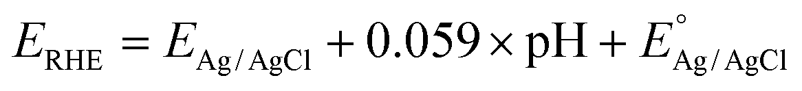
| Fig. 1 Preparation and structural characterization of the CoSx@NF electrode: (a) schematic diagram for the preparation of the CoSx@NF electrode by electrodeposition for lignin depolymerization and hydrogen evolution; (b) and (c) TEM images; (d) HRTEM image; (e) SAED pattern; (f) EDS spectrum images; (g) SEM image; (h) XRD spectra of CoSx@NF (top line) and Ni (bottom line); and (i) XPS spectrum of Co 2p of CoSx@NF. | ||
The performance of the electrodes prepared by electrodeposition for different times was investigated, as shown in ESI Fig. S1.† The current densities of all electrodes increased significantly for potentials of −1.2 to −1.8 V after addition of lignin, indicating that the electrodeposited active layer had a strong catalytic effect on lignin oxidation. As observed in Fig. S1a,† the oxidation current of lignin increased with deposition time, but after the deposition time exceeded 3 minutes, the oxidation current plateaued. SEM images of the electrodes prepared using different deposition times are shown in Fig. S2.† At a deposition current of 1 A cm−2, a 3D microspherical nanoarray structure could be formed on the nickel foam skeleton. The microspheres obtained by deposition for 1 minute were smaller, and a higher magnification image revealed that these microspheres were composed of nanosheet arrays. As the deposition time was extended to 3 minutes, the microspheres grew larger, and high-magnification microscopy images showed a nanoflower spherical structure formed by cross-stacked nanosheets. However, when the deposition time was extended to 6 minutes, the nanosheets within the microspheres became less distinct, and the microsphere diameter decreased. Thus, electrodeposition for 3 minutes could achieve an optimal micromorphology of the cobalt active layer. Similarly, increasing the deposition current density could significantly increase the amount of deposited cobalt sulfide. As shown in Fig. S3,† at a relatively low deposition current density of 0.2 A cm−2, only a single layer of small microspheres was deposited on the electrode surface. However, as the deposition current increased to 1 A cm−2, the microspheres on the electrode surface exhibited a multi-layer morphology and increased in size. Therefore, the appropriate deposition current was determined to be 1 A cm−2. The microspherical structure on the electrode could significantly increase the specific surface area with a high loading capacity of the electrocatalyst. Moreover, the nanosheet structure in the nanoflower spheres further increased the specific surface area, exposing more catalytically active sites. As shown in Fig. S1b,† the oxidation current of lignin indeed increased gradually with the increase in electrodeposition current density. This indicated that by using electrodeposition at a relatively high current density (1 A cm−2), a large amount of active cobalt species could be deposited on the Ni foam matrix and the 3D structure of the catalysts could be well constructed. It should be noted that at higher current density, the multi-layer morphology of the electrodeposited cobalt catalysts may lead to aggregation, which may further decrease the surface active sites compared to a single layer or bilayers of CoSx formed at lower current density. Therefore, more electrochemical performance parameters of the catalysts should be further tested.
Fig. S7† shows the Nyquist curves of different electrodes, where the impedance behavior reflects the reaction kinetics of the interface between the electrode and the electrolyte.18 The equivalent circuit model is constructed by measuring the electrochemical impedance spectrum, and it is usually composed of solution resistance (Rs), constant phase angle element (CPE) and charge transfer resistance (Rct).17 The semicircle (capacitive reactance arc) corresponding to the high-frequency region of the Nyquist curve is associated with Rct. A smaller semicircle radius indicates a lower Rct and better conductivity of the electrode material. As shown in Fig. S7,† compared with the unmodified nickel foam (Rct 480.33 Ω), CoSx@NF had a lower charge transfer resistance Rct (13.25 Ω), indicating easier charge transfer between the CoSx@NF electrode and the electrolyte and better conductivity of the electrode material. After adding lignin, the Rct of CoSx@NF was further decreased to 9 Ω, indicating an accelerated electron transfer rate on the electrode surface and demonstrating good catalytic activity for lignin oxidation. The horizontal coordinate of the intersection of the Nyquist curve and the real axis (Z′ axis) represents the solution resistance (Rs). After addition of lignin, Rs increased slightly, indicating a slight increase in the resistance of the electrolyte solution itself, suggesting that the resistance encountered by ions moving in the lignin solution also increased slightly. However, since the Rs was relatively small, ranging from 0.98 to 1.9 Ω, it could be considered negligible compared with Rct. These results show that charge transfer at the electrode–electrolyte interface was the rate-controlling step, and thus the development of efficient electrode catalysts was particularly critical. The CoSx@NF electrode prepared by electrodeposition showed a significant reduction in Rct from 480.33 Ω to 13.25 Ω, thereby demonstrating excellent electrochemical performance.
![[thin space (1/6-em)]](https://www.rsc.org/images/entities/char_2009.gif) 36 and ferricyanides,37 while efficient solid mediators (catalysts) are metal sulfides.3 For the cathode electron mediators, various metal-based redox couples such as (VO2)2SO4, POMs, and Fe(NO3)3 have been used to facilitate the electron transfer to oxygen, among which (VO2)2SO4 showed the best performance for electricity generation.37 Consequently, the CoSx@NF electrode was employed as the anode of the fuel cell system with (VO2)2SO4 as the electron mediator at the cathode for discharge testing. As shown in Fig. 2, when Nafion 117 was used as the proton exchange membrane and sodium lignosulfonate or alkali lignin as the substrate, the peak power density of the DLFC using the CoSx@NF anode was 149.4 mW cm−2 and 113.2 mW cm−2, respectively, significantly higher than the peak power density of the cell without lignin (69.0 mW cm−2). When Nafion 211 was used as the proton exchange membrane, the discharge performance of the DLFC improved significantly, with a peak power density of 196.1 mW cm−2 when sodium lignosulfonate was used as the substrate. These discharging results indicated that the CoSx@NF anode exhibited excellent performance in DLFCs for electricity generation.
36 and ferricyanides,37 while efficient solid mediators (catalysts) are metal sulfides.3 For the cathode electron mediators, various metal-based redox couples such as (VO2)2SO4, POMs, and Fe(NO3)3 have been used to facilitate the electron transfer to oxygen, among which (VO2)2SO4 showed the best performance for electricity generation.37 Consequently, the CoSx@NF electrode was employed as the anode of the fuel cell system with (VO2)2SO4 as the electron mediator at the cathode for discharge testing. As shown in Fig. 2, when Nafion 117 was used as the proton exchange membrane and sodium lignosulfonate or alkali lignin as the substrate, the peak power density of the DLFC using the CoSx@NF anode was 149.4 mW cm−2 and 113.2 mW cm−2, respectively, significantly higher than the peak power density of the cell without lignin (69.0 mW cm−2). When Nafion 211 was used as the proton exchange membrane, the discharge performance of the DLFC improved significantly, with a peak power density of 196.1 mW cm−2 when sodium lignosulfonate was used as the substrate. These discharging results indicated that the CoSx@NF anode exhibited excellent performance in DLFCs for electricity generation.
 | ||
| Fig. 2 Direct conversion of lignin to electricity with CoSx@NF as the anode: (a) the working principle of the direct lignin fuel cell; (b) power density of the fuel cell equipped with a Nafion 117 membrane; and (c) power density of the fuel cell equipped with a Nafion 211 membrane. | ||
The change in the yield of aromatic aldehydes with varying electrolysis voltage is shown in Fig. 3. As the electrolysis voltage increased from 1 V to 1.2 V, the yields of p-hydroxybenzaldehyde, vanillin and syringaldehyde exhibited an increasing trend. This increase was attributed to the higher electrolysis voltage elevating the current density and accelerating the rate of lignin oxidation on the anode. However, when the voltage exceeded 1.2 V, the yield of aromatic aldehydes initially increased and then decreased, indicating that the aromatic aldehydes were over-oxidized. Notably, the yield of syringaldehyde was the highest at an electrolysis voltage of 1.1 V, reaching 1.20%. Among the three aromatic aldehydes, syringaldehyde was the most sensitive to the reaction conditions, followed by vanillin and then p-hydroxybenzaldehyde. This order of reaction activity is consistent with the reported literature.38 Overall, the optimal electrolysis voltage for the electrolysis system was determined to be 1.2 V, at which the total yield of aromatic aldehydes reached 5.53%, with yields of 0.99% for p-hydroxybenzaldehyde, 3.57% for vanillin, and 0.97% for syringaldehyde.
 | ||
| Fig. 3 Effect of electrolysis voltage on the yields of aromatic aldehydes prepared by electro-oxidative depolymerization of lignin: (a) p-hydroxybenzaldehyde; (b) vanillin; (c) syringaldehyde; and (d) total aromatic aldehydes (reaction conditions: Clignin, 2 g L−1; CKOH, 3 mol L−1; T, 80 °C; A, 2 × 2 cm2 electrode area); and (e) possible reaction mechanism of lignin oxidation on the CoSx@NF anode. | ||
The effect of alkali concentration on the yield of aromatic aldehydes is shown in Fig. S8.† The yield of aromatic aldehydes increased with increasing alkali concentration. On the one hand, a higher alkali concentration increased the concentration of supporting electrolytes, reduced the internal resistance of the electrolytic cell, and increased the current density in the circuit, thereby accelerating the lignin oxidation reaction at the anode. On the other hand, OH− participated in the oxidation and cleavage of ether bonds and carbon–carbon bonds in the lignin side chain, and their increased concentration promoted the formation of aromatic aldehydes. However, when the alkali concentration exceeded 3 mol L−1, the yield of aromatic aldehydes decreased slightly, possibly due to the strongly alkaline conditions causing lignin intermediates to undergo polycondensation or further oxidation of the aromatic aldehydes. Therefore, the optimal alkali concentration was determined to be 3 mol L−1.
The effect of lignin concentration on the yield of aromatic aldehydes is shown in Fig. S9.† The yields of aromatic aldehydes increased as the lignin concentration decreased. When the lignin concentration was 4 g L−1, the total yield of aromatic aldehydes was only 4.18%. At this concentration, the high lignin content might increase the viscosity of the electrolyte solution, leading to higher internal resistance in the electrolytic cell, and the higher lignin concentration might have blocked the catalyst pores, resulting in electrocatalyst deactivation. When the lignin concentration was reduced to 0.5 g L−1, the total yield of aromatic aldehydes increased to 8.10%, with yields of 1.55% for p-hydroxybenzaldehyde, 5.00% for vanillin, and 1.54% for syringaldehyde.
Reaction temperature is an important factor affecting lignin oxidative depolymerization in the electrolytic cell. As shown in Fig. S10,† the yield of aromatic aldehydes increased with increasing temperature. When the temperature of the electrolytic cell was 25 °C, the total yield of aromatic aldehydes was only 1.61%. However, when the reaction temperature increased to 90 °C, the total yield of aromatic aldehydes increased to 6.01%, with yields of 1.15% for p-hydroxybenzaldehyde, 3.82% for vanillin, and 1.04% for syringaldehyde. This was primarily due to the increase in temperature, which reduced the internal resistance of the electrolytic cell and enhanced the rate of lignin oxidative depolymerization. Considering that further increasing the temperature could cause damage to the ion exchange membrane of the electrolytic cell, the optimal reaction temperature was determined to be 90 °C.
A comparison of the recently reported studies on electrooxidative depolymerization of lignin for the production of aromatic aldehydes is shown in Table S1.† The yields of aromatic aldehydes obtained in this work were in the ranges similar to those in the reported works. However, compared with the results of lignin depolymerization under mild conditions (<100 °C), the yields of aromatic aldehydes obtained in this work were at the highest levels, primarily due to the superior performance of the developed catalysts. Nevertheless, it should be noted that the yield of aromatic aldehydes is profoundly affected by the type and origin of the lignin feedstock, as structural differences stemming from various isolation methods can substantially alter its reactivity during electro-oxidative depolymerization. For example, in our previous work on electrooxidative depolymerization of various types of lignin with a DLFC equipped with a CoS@NF anode,6 Kraft lignin achieved a total aromatic aldehyde yield of 7.2%, predominantly comprising 6.9% vanillin, whereas POM-treated enzymatic lignin yielded a mere 1.0% under identical conditions. This stark contrast highlights the critical role of lignin composition and pretreatment in determining the efficiency of the depolymerization process.
The possible mechanism of lignin depolymerization on the CoSx@NF electrode is shown in Fig. 3e. The Co3+/Co2+ redox couple plays a pivotal role in mediating this process through a free radical mechanism. Under anodic conditions, Co2+ species on the catalyst surface are oxidized to Co3+ by the applied potential. Subsequently, Co3+ reacts with hydroxide ions (OH−) or water in the alkaline electrolyte to generate reactive oxygen species (ROS), such as hydroxyl radicals (˙OH). These ROS are highly reactive and capable of cleaving C–C and C–O bonds in lignin, leading to its depolymerization and the formation of aromatic aldehydes (e.g., p-hydroxybenzaldehyde, vanillin, and syringaldehyde). This process regenerates Co2+, completing the redox cycle.6 Supporting this mechanism, XPS analysis of the used CoSx@NF anode (Fig. S11†) revealed an increase in the relative content of Co3+ (binding energies at 779.5 eV and 794.8 eV) compared to Co2+ (780.9 eV and 796.6 eV), indicating the oxidation of Co2+ to Co3+ during the reaction. Additionally, XRD analysis of the used anode showed a weak diffraction peak corresponding to CoOOH, a Co3+-containing phase, further confirming the presence of Co3+ species. This suggests a dynamic redox cycle where Co2+ is continuously oxidized to Co3+ at the anode, with some Co3+ stabilized as CoOOH, while ROSs drive the oxidation of lignin. This free radical mechanism not only explains the efficient depolymerization of lignin but also aligns with analogous cobalt-based catalytic systems used for the oxidation of some organic substrates.39,40
3.2. Hydrogen evolution performance of the CoSx@NF electrode
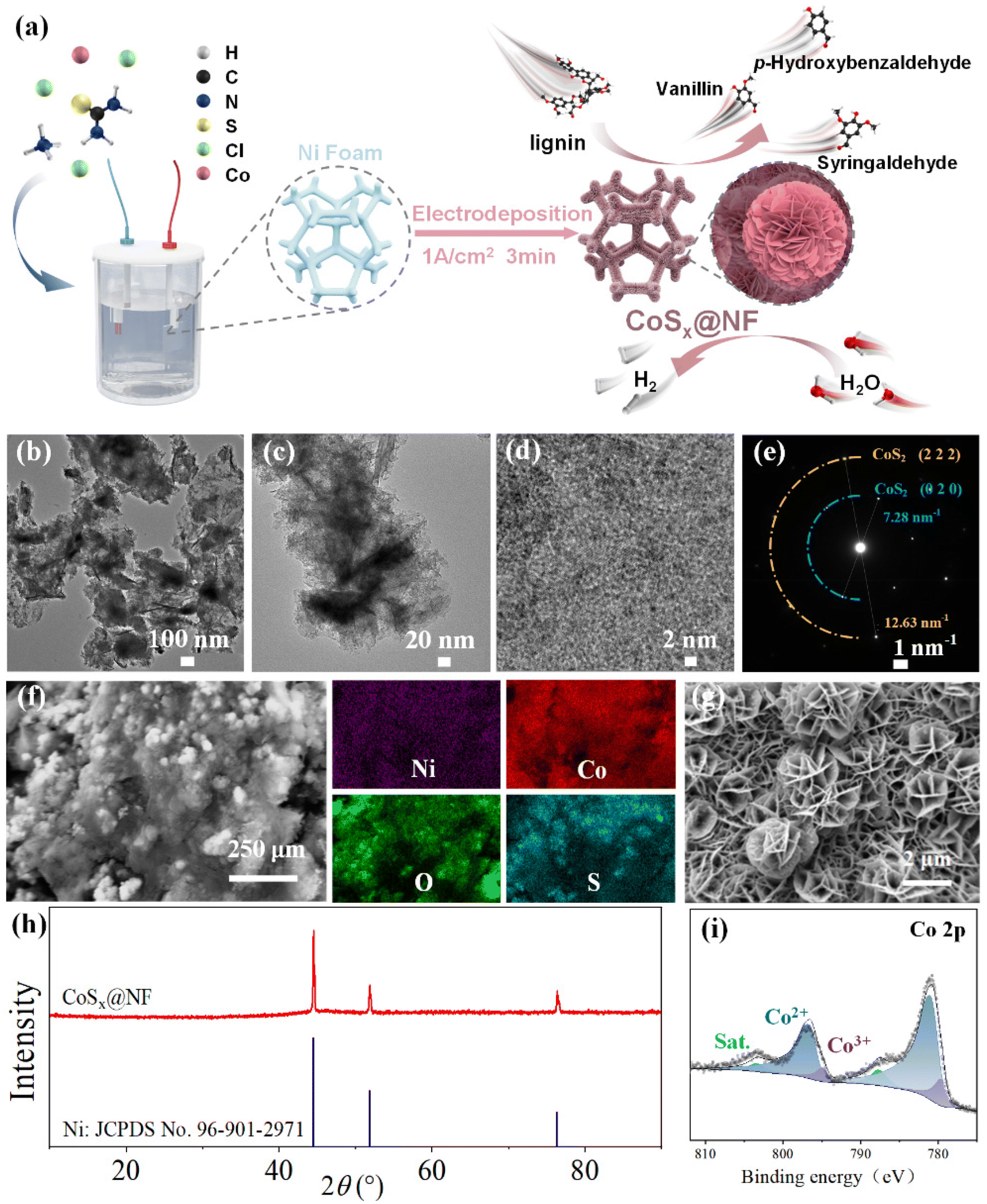
The hydrogen evolution polarization curves of different types of electrodes were further compared. As shown in Fig. 4, the hydrogen evolution activity of the modified NF electrode was significantly improved, and the performance of the CoSx@NF electrode was comparable to that of commercial Pt/C@NF. At a lower current density (less than 250 mA cm−2), the hydrogen evolution overpotential of the Pt/C@NF electrode was smaller than that of the CoSx@NF electrode, while at a higher current density (more than 250 mA cm−2), the hydrogen evolution overpotential of the CoSx@NF electrode was similar to or even smaller than that of the Pt/C@NF electrode. According to the results in Fig. 4a, the overpotentials for the hydrogen evolution reactions of the different electrodes are shown in Fig. 4b. At a current density of 10 mA cm−2, the hydrogen evolution overpotential of the CoSx@NF electrode was only 23 mV in 1 mol L−1 KOH electrolyte, similar to that of the Pt/C@NF electrode (30 mV), while the hydrogen evolution overpotential of the unmodified nickel foam was as high as 202 mV. At a current density of 100 mA cm−2, the hydrogen evolution overpotential of the CoSx@NF electrode was 153 mV, much lower than that of nickel foam (369 mV), while the performance of the Pt/C@NF electrode (111 mV) was slightly better than that of the CoSx@NF electrode. These results can be explained by considering two factors: the electrochemical activity of the electrode material and its morphology. The binding energy between the catalyst and adsorbed hydrogen is a crucial factor affecting the rate of the HER. According to the volcano plot curve reported in a previous study,41 Pt is located at the top of the “volcano curve”, indicating that its binding energy with hydrogen is moderate, and it has the highest exchange current density, making it the best HER catalytic material. Metals located to the left side of Pt on the curve have progressively stronger hydrogen binding energy, causing the adsorbed hydrogen to bind tightly to the active sites and preventing desorption, which is detrimental to the reaction. Conversely, metals to the right of Pt have weaker binding energies, leading to less adsorbed hydrogen on the catalyst surface and slower reaction rates. Co is located on the left side of Pt, and has a binding energy similar to Pt, resulting in good catalytic activity. Additionally, the surface morphology of the electrode plays a crucial role in determining the hydrogen evolution overpotential. The CoSx@NF electrode catalyst has a large specific surface area, and its nanoporous structure allows effective gas diffusion, enhancing mass transfer performance,19 which contributes to reducing the overpotential of the hydrogen evolution reaction. Consequently, the CoSx@NF electrode demonstrated excellent hydrogen evolution catalytic activity.
 | ||
| Fig. 4 Hydrogen evolution performance test of different electrodes and Gibbs free energy and Bader charge analysis for the HER. (a) Polarization curves in 1 mol L−1 KOH electrolyte; (b) comparison of hydrogen evolution overpotentials in 1 mol L−1 KOH electrolyte; (c) Tafel slopes; (d) exchange current density; (e) Nyquist curves of CoSx@NF and Pt/C@NF cathodes in the high-frequency region at 113 mV overpotential; (f) long-term stability test showing potential–time curves of hydrogen evolution electrolysis at different electrodes; (g) Gibbs free energy of H adsorption (ΔGH*) on CoS2 (111), CoS2 (010), Pt (111), and Ni (111); and (h) Bader charge of adsorbed H2O on CoS2 (111), CoS2 (010), Pt (111), and Ni (111). | ||
The electrochemical impedance spectra were fitted using the Randles equivalent circuit model,43 and the results are shown in Fig. S13a† and Fig. 4e. Compared with the unmodified nickel foam (Rct was 96.44 Ω), the CoSx@NF electrode exhibited a much lower charge transfer resistance (Rct was 4.08 Ω), indicating enhanced conductivity and accelerated charge transfer. This improvement might be attributed to its large active area and abundant catalytically active sites, leading to better hydrogen evolution performance. Additionally, the Pt/C@NF electrode had an even lower Rct value (2.02 Ω), confirming that the precious metal was indeed highly active in catalyzing the hydrogen evolution reaction. The impedance of the CoSx@NF electrode was measured at different overpotentials. As shown in Fig. S13b,† as the overpotential increased, the capacitive arc radius gradually decreased, indicating a reduction in charge transfer resistance. Thus, increasing the polarization potential was conducive to accelerating the hydrogen evolution reaction rate. This phenomenon was consistent with the conclusion reported by Liao et al.44 Compared with the catalytic performance of related hydrogen evolution electrodes reported in recent years, as shown in Table S3,† the CoSx@NF electrode developed in this study had excellent catalytic performance, especially demonstrating a low overpotential.
To test the stability of the electrode, a relatively long-term electrolysis experiment was conducted, and the results are shown in Fig. 4f. At a constant current density of 10 mA cm−2, the hydrogen evolution catalytic activity of the CoSx@NF electrode did not decay significantly over an 80-hour operation period. The hydrogen evolution overpotential remained between 96 and 120 mV, and no significant shedding of the active layer on the electrode surface was observed after electrolysis, indicating that the electrode has excellent electrocatalytic stability. Additionally, the hydrogen evolution overpotentials of several other electrodes were compared. The Pt/C@NF electrode exhibited superior hydrogen evolution performance with an overpotential of only 62 mV. The overpotential of nickel foam was as high as 361 mV, while the CoSx@NF electrode reduced the overpotential by approximately 253 mV, demonstrating that the energy consumption of the hydrogen evolution half reaction could be reduced by about 70%.
The Gibbs free energy of H adsorption (ΔGH*) is considered a critical indicator for evaluating HER catalysts. For an effective HER catalyst, the adsorption and desorption of H should be thermodynamically balanced. The closer the ΔGH* is to zero, the higher the expected HER activity. As shown in Fig. 4g, the Gibbs free energies for H adsorption on the CoS2 (111) and (010) facets are 0.26 eV and 0.24 eV, respectively, which are closer to the −0.15 eV value for the Pt (111) facet and significantly lower than the −0.61 eV for the Ni (111) facet. The small positive ΔG values indicate weak H adsorption on these CoS2 facets, which, compared to the strong H adsorption on Ni (111), is more favorable for the HER process.
The dissociation of water is another crucial step in the HER process. Fig. 4h shows the Bader charges of H2O on these four different surfaces, where the Bader charges on the CoS2 (111) and (010) facets are +0.013e− and +0.048e−, respectively, while the Ni (111) and Pt (111) facets have Bader charges of +0.039e− and +0.101e−, respectively. This indicates that, during adsorption, electrons are transferred from H2O to the catalyst. The higher Bader charge of H2O on the CoS2(010) facet than that on Ni (111) suggests a water activation ability closer to that of Pt, which favors the dissociation process of water.
In conclusion, both experimental and theoretical results confirm that the CoSx@NF catalyst optimizes the H adsorption and H2O dissociation processes, thereby exhibiting excellent HER activity.
3.3. Coupling a direct lignin fuel cell with an electrolysis system
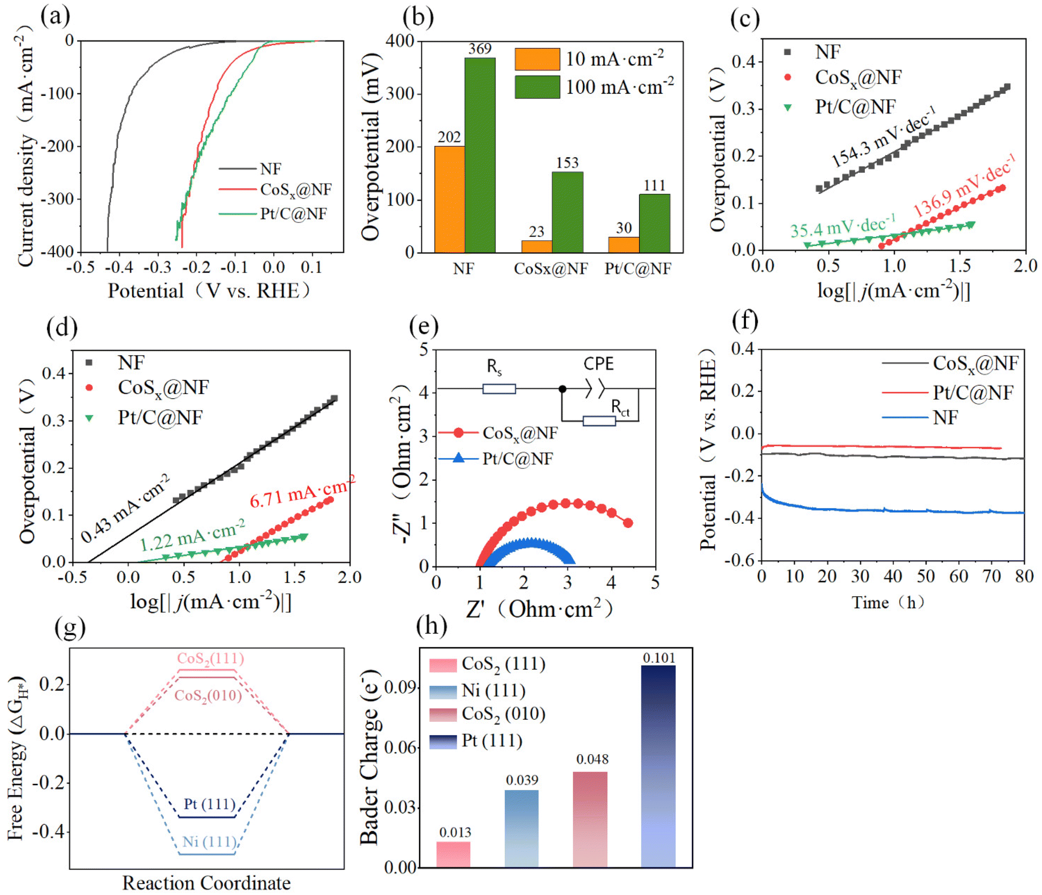
Because the CoSx@NF catalyst showed excellent performance in lignin oxidation and the HER, a coupled system was further constructed by coupling a DLFC with an electrolysis system (Fig. 5a) to achieve co-production of aromatic aldehydes and H2 through transfer of the endogenous electrons from lignin to water. In this coupled system, the DLFC provides electricity to the electrolysis cell, resulting in the formation of aromatic aldehydes at the anodes of both the fuel cell and the electrolysis cell, while H2 was generated at the cathode of the electrolysis cell. The primary driving force of the system is the Gibbs energy change of lignin oxidation by VO2+. Such a coupled system can achieve production of high value-added products (aromatic compounds) and green hydrogen without using external electricity. As depicted in ESI Fig. S16,† the oxidation of lignin at the DLFC anode generates electrons, which are transferred to the DLFC cathode, reducing V5+ (in (VO2)2SO4) to V4+ (VOSO4). This process produces electrical energy, with the output voltage (VDLFC output) corresponding to the potential difference between the lignin oxidation and vanadium reduction reactions, as dictated by their polarization curves. The generated electricity powers the electrolytic cell, where lignin is oxidized at the anode to yield aromatic aldehydes (e.g., p-hydroxybenzaldehyde, vanillin, and syringaldehyde), while water is reduced at the cathode via the HER to produce H2. The input voltage of the electrolytic cell (Vinput) reflects the potential difference between the HER and lignin oxidation reactions. | ||
| Fig. 5 Schematic and performance evaluation of the system for lignin oxidation coupled with hydrogen evolution: (a) schematic diagram of the coupled system (DLFC and the electrolytic cell); (b) effect of lignin addition after 1 hour on hydrogen evolution electrolysis current; (c) continuous electrolysis for 2 hours with and without lignin addition at room temperature and 80 °C. Yields of aromatic aldehydes prepared by depolymerization of lignin at the DLFC anode and the electrolytic cell anode in the coupled system: (d) p-hydroxybenzaldehyde; (e) vanillin; (f) syringaldehyde; and (g) total aromatic aldehydes (the reaction conditions of the DLFC and electrolytic cell: Clignin, 2 g L−1; CKOH, 3 mol L−1; A, 2 × 2 cm2 electrode area). | ||
Before running the coupled system, we investigated the effects of lignin oxidation on the electrolytic current of hydrogen evolution in a flow electrolysis cell. As shown in Fig. 5b, at room temperature and a voltage of 1.2 V, the current was nearly zero within the first hour in 1 mol L−1 KOH electrolyte, indicating that no reaction took place in the electrolysis system. Then, 2 g L−1 lignin was added to the anode solution, and the current density increased rapidly and significantly. When the reaction temperature was increased to 80 °C, the increase in the current density was even more pronounced. Additionally, the current exhibited a wavy pattern. This was due to the integration of a negative feedback temperature controller with the heating device of the electrolytic cell, resulting in heat exchange between the surrounding environment and the electrolytic cell. Consequently, the temperature fluctuated around the set target temperature, causing the fluctuation trend of the current density. Initially, without lignin, the current was large within the first hour. This was because the active species of the electrocatalyst underwent rapid oxidation at this electrolysis voltage. Once the active species reached equilibrium, the hydrogen evolution current remained stable at a current density of 2.85 mA cm−2, indicating that the oxygen evolution reaction occurred at the anode at this voltage. When lignin was added after 1 h, the initial current was significantly enhanced due to the oxidation of the functional groups of lignin that were easy to oxidize. As the reaction proceeded, the concentration of highly reactive substances in lignin decreased, and the current gradually decreased.
Fig. 5b shows the change in current density with and without adding lignin at the beginning of the reaction during 2 h continuous electrolysis. The system of lignin oxidation coupled with the HER exhibited higher current density than water electrolysis at the same potential. At room temperature, the average current density increased from 0.35 mA cm−2 to 2.03 mA cm−2 after adding lignin, while the average current density increased from 3.63 mA cm−2 to 5.83 mA cm−2 at 80 °C. Since the cathode electrolyte was KOH solution, hydrogen production followed Faraday's law.45 Therefore, when the electrolysis voltage applied to the electrolytic cell was 1.2 V at room temperature, the H2 production capacity reached 0.845 mL h−1 cm−2 (electrode area) when lignin was added, representing a 479% increase in hydrogen production efficiency compared to the control system without addition of lignin (0.146 mL h−1 cm−2). At 80 °C, the H2 production capacity was 2.44 mL h−1 cm−2, which was 61% higher than that of the control system (1.52 mL h−1 cm−2).
Two DLFCs (each with an electrode area of 2 × 2 cm2) were connected in series to power the electrolysis cell device. As shown in Fig. S17,† the electrolysis voltage was maintained between 1.3 and 1.4 V, and the electrolysis current density ranged from 10 to 25 mA cm−2. The current density was relatively high at the early stage due to the high initial lignin concentration in the DLFC and the electrolysis cell. As the reaction proceeded, the lignin concentration decreased, resulting in a corresponding decrease in current density. For comparison, the current density during constant voltage electrolysis with an electrochemical workstation as a power source was recorded. The current density of the coupled system was within the range of that obtained in constant–voltage electrolysis at 1.3 V and 1.4 V, indicating that the coupled system could achieve a similar performance to the standalone electrolysis system.
Fig. 5d–g show the yields of aromatic aldehydes in the coupled system. It is clear that the coupled system successfully achieved oxidative depolymerization of lignin to produce aromatic aldehydes while simultaneously generating H2 at the cathode of the electrolytic cell. For the anodic reaction of the DLFC, the highest total aromatic aldehyde yield was observed at 20 minutes, reaching 2.90%, with yields of 0.82% for p-hydroxybenzaldehyde, 1.60% for vanillin, and 0.48% for syringaldehyde. For the anodic reaction in the electrolysis cell, the highest total aromatic aldehyde yield was observed at 30 minutes, reaching 3.34%, with yields of 0.75% for p-hydroxybenzaldehyde, 1.95% for vanillin, and 0.64% for syringaldehyde. At this time, the H2 production at the cathode reached 12.7 mL cm−2. These results confirm the feasibility of the coupled system to produce aromatic aldehydes and H2. Based on the optimization results for the production of aromatic aldehydes, an electrolysis voltage of 1.2 V was found to be preferable. Therefore, the electrolysis voltage could be further adjusted by connecting a variable resistor box in series in the circuit to achieve higher yields of aromatic aldehydes. However, such a coupled system still needs further optimization including the design of the system as well as operating parameters to improve stability and increase efficiency. In particular, the matching of the electrode reaction rates between the DLFC and the electrolytic cell is important to maximize the yields of aromatic aldehydes and hydrogen.
4. Conclusions
An efficient bifunctional electrocatalyst, CoSx@NF, with a 3D nanoflower spherical morphology composed of nanosheets was developed through a high current density electrodeposition process. The catalyst showed good performance for the anodic oxidation of lignin to obtain aromatic aldehydes as well as the cathodic HER to produce H2. The unique 3D structure endowed the catalyst with a high specific surface area, and the hierarchical porous nature facilitated the rapid escape of gas, thereby enhancing the material's stability. The CoSx@NF electrocatalyst could well work as an anode in a DLFC to effectively convert lignin to electricity with a maximal power density of 196.1 mW cm−2 at 90 °C. The CoSx@NF electrode also showed good performance in an electrolytic cell to catalyze the electro-oxidative depolymerization of lignin, yielding aromatic aldehydes. At an electrolysis voltage of 1.2 V and a lignin concentration of 0.5 g L−1, the total yield of aromatic aldehydes reached 8.10%. Additionally, the CoSx@NF cathode demonstrated excellent hydrogen evolution catalytic activity. At current densities of 10 mA cm−2 and 100 mA cm−2, the hydrogen evolution overpotentials were only 23 mV and 153 mV, respectively. Pairing lignin oxidation with the hydrogen evolution process resulted in higher current density at the same electrolysis potential. A novel coupled system was further developed by coupling the DLFC with the electrolytic cell to achieve co-production of aromatic aldehydes and H2 without the input of external electricity. The highest yields of total aromatic aldehydes at the anodes of the DLFC and electrolytic cell were 2.90% and 3.34%, respectively, with an H2 production of 12.7 mL cm−2 at the cathode of the electrolytic cell, demonstrating the success of the coupled system. This work may thus provide novel ideas to develop green systems for the conversion of lignin to high value-added chemicals and renewable fuels.Author contributions
Yichen Zhang: methodology, formal analysis, investigation, resources, data curation, writing – original draft, and visualization. Daihong Gao: methodology, formal analysis, investigation, data curation, visualization and writing – original draft. Denghao Ouyang: formal analysis, investigation, and visualization. Binhang Yan: resources, software, and formal analysis. Xuebing Zhao: conceptualization, resources, funding acquisition, project administration, supervision, and writing – review and editing.Conflicts of interest
The authors declare no conflicts of interest.Data availability
The data supporting this article have been included as part of the ESI.†Acknowledgements
This work was supported by the National Natural Science Foundation of China (No. 22178197; U23A6005; 22478222) and the Dr Jentai Yang Sustainable Environmental Protection and Eco-humanistic Education Fund (No. 20253000027). The theoretical computation part of this research was supported by the Centre for High Performance Computing, Tsinghua University.References
- M. J. Gan, Y. Q. Niu, X. J. Qu and C. H. Zhou, Green Chem., 2022, 24, 7705–7750 RSC.
- A. Beaucamp, M. Muddasar, I. S. Amiinu, M. Moraes Leite, M. Culebras, K. Latha, M. C. Gutiérrez, D. Rodriguez-Padron, F. del Monte, T. Kennedy, K. M. Ryan, R. Luque, M.-M. Titirici and M. N. Collins, Green Chem., 2022, 24, 8193–8226 RSC.
- D. Ouyang, D. Gao, Y. Qiang and X. Zhao, Appl. Catal., B, 2023, 328, 122491 CrossRef CAS.
- Z. Xie, X. Zu, J. Lin, X. Qiu, T. Liang and L. Chen, Green Chem., 2024, 26, 2021–2030 RSC.
- T. Liang, X. Zu, B. Liu, X. Qiu, Z. Xie, X. Wang and D. Yang, Green Chem., 2024, 26, 4811–4819 RSC.
- D. Gao, D. Ouyang and X. Zhao, Chem. Eng. J., 2024, 479, 147874 CrossRef CAS.
- S. Chu and A. Majumdar, Nature, 2012, 488, 294–303 CrossRef CAS PubMed.
- F. Sheng, Q. Yang, D. Cui, C. Liu, Y. Sun, X. Wang and W. Su, Energy Fuels, 2020, 34, 10282–10289 CrossRef CAS.
- H. Zhao, D. Lu, J. Wang, W. Tu, D. Wu, S. W. Koh, P. Gao, Z. J. Xu, S. Deng, Y. Zhou, B. You and H. Li, Nat. Commun., 2021, 12, 2008 CrossRef CAS PubMed.
- H.-Y. Wang, M.-L. Sun, J.-T. Ren and Z.-Y. Yuan, Adv. Energy Mater., 2023, 13, 2203568 CrossRef CAS.
- W. Gao, C. Wang, W. Wen, S. Wang, X. Zhang, D. Yan and S. Wang, Adv. Mater., 2025, 2503198, DOI:10.1002/adma.202503198.
- S. Aralekallu, L. K. Sannegowda, M. D. Kurkuri, R. K. Pai and H.-Y. Jung, Sustainable Energy Fuels, 2025, 9, 2928–2940 RSC.
- N. Jiang, B. You, R. Boonstra, I. M. Terrero Rodriguez and Y. Sun, ACS Energy Lett., 2016, 1, 386–390 CrossRef CAS.
- M. Ito, T. Hori, S. Teranishi, M. Nagao and T. Hibino, Sci. Rep., 2018, 8, 16186 CrossRef PubMed.
- H. R. Ghatak, S. Kumar and P. P. Kundu, Int. J. Hydrogen Energy, 2008, 33, 2904–2911 CrossRef CAS.
- H. Royghatak, Int. J. Hydrogen Energy, 2006, 31, 934–938 CrossRef.
- W.-J. Liu, Z. Xu, D. Zhao, X.-Q. Pan, H.-C. Li, X. Hu, Z.-Y. Fan, W.-K. Wang, G.-H. Zhao, S. Jin, G. W. Huber and H.-Q. Yu, Nat. Commun., 2020, 11, 265 CrossRef CAS PubMed.
- S. Shen, Z. Wang, Z. Lin, K. Song, Q. Zhang, F. Meng, L. Gu and W. Zhong, Adv. Mater., 2022, 34, e2110631 CrossRef PubMed.
- W. Hong, C. Jian, G. Wang, X. He, J. Li, Q. Cai, Z. Wen and W. Liu, Appl. Catal., B, 2019, 251, 213–219 CrossRef CAS.
- Giddaerappa, N. Kousar, U. Deshpande and L. K. Sannegowda, Energy Fuels, 2024, 38, 8249–8261 CrossRef CAS.
- S. Gaddimath, A. Shambhulinga, P. C. Keshavanada, D. Shantharaja, Giddaerappa and L. K. Sannegowda, Int. J. Hydrogen Energy, 2024, 110, 181–207 CrossRef.
- G. Kresse and J. Furthmüller, Comput. Mater. Sci., 1996, 6, 15–50 CrossRef CAS.
- G. Kresse and J. Furthmüller, Phys. Rev. B: Condens. Matter Mater. Phys., 1996, 54, 11169–11186 CrossRef CAS PubMed.
- J. P. Perdew, K. Burke and M. Ernzerhof, Phys. Rev. Lett., 1996, 77, 3865–3868 CrossRef CAS PubMed.
- G. Kresse and D. Joubert, Phys. Rev. B: Condens. Matter Mater. Phys., 1999, 59, 1758–1775 CrossRef CAS.
- H. J. Monkhorst and J. D. Pack, Phys. Rev. B, 1976, 13, 5188–5192 CrossRef.
- W. Xie, K. Liu, G. Shi, X. Fu, X. Chen, Z. Fan, M. Liu, M. Yuan and M. Wang, J. Energy Chem., 2021, 60, 272–278 CrossRef CAS.
- Z. Fang, F. Li, M. Wang, F. Li, X. Wu, K. Fan, Q. Tang, L. Sun and P. Zhang, Appl. Catal., B, 2023, 323, 122149 CrossRef CAS.
- N. S. McIntyre and M. G. Cook, Anal. Chem., 1975, 47, 2208–2213 CrossRef CAS.
- R. Luo, Y. Li, L. Xing, N. Wang, R. Zhong, Z. Qian, C. Du, G. Yin, Y. Wang and L. Du, Appl. Catal., B, 2022, 311, 121357 CrossRef CAS.
- A. Mosallanezhad, C. Wei, P. Ahmadian Koudakan, Y. Fang, S. Niu, Z. Bian, B. Liu, T. Huang, H. Pan and G. Wang, Appl. Catal., B, 2022, 315, 121534 CrossRef CAS.
- W. Chen, X. Zhu, R. Wang, W. Wei, M. Liu, S. Dong, K. K. Ostrikov and S.-Q. Zang, J. Energy Chem., 2022, 75, 16–25 CrossRef CAS.
- D. Ouyang, F. Wang, H. Yang and X. Zhao, Chem. Eng. J., 2021, 420, 129716 CrossRef CAS.
- W. Liu, W. Mu, M. Liu, X. Zhang, H. Cai and Y. Deng, Nat. Commun., 2014, 5, 3208 CrossRef PubMed.
- Y.-A. Chen, H. Yang, D. Ouyang, T. Liu, D. Liu and X. Zhao, Appl. Catal., B, 2020, 265, 118578 CrossRef CAS.
- X. Zu, L. Sun, J. Gong, X. Liu, Y. Liu, X. Du, W. Liu, L. Chen, G. Yi, W. Zhang, W. Lin, W. Li and Y. Deng, Chem. Eng. J., 2018, 348, 476–484 CrossRef CAS.
- D. Ouyang, F. Wang, J. Hong, D. Gao and X. Zhao, Appl. Energy, 2021, 304, 117927 CrossRef CAS.
- M. I. de Heer, H.-G. Korth and P. Mulder, J. Org. Chem., 1999, 64, 6969–6975 Search PubMed.
- Y. Li, Z. Dang and P. Gao, Nano Sel., 2021, 2, 847–864 CrossRef CAS.
- Y.-Q. Zhu, H. Zhou, J. Dong, S.-M. Xu, M. Xu, L. Zheng, Q. Xu, L. Ma, Z. Li, M. Shao and H. Duan, Angew. Chem., Int. Ed., 2023, 62, e202219048 Search PubMed.
- W. Sheng, M. Myint, J. G. Chen and Y. Yan, Energy Environ. Sci., 2013, 6, 1509 RSC.
- L. Li, P. Wang, Q. Shao and X. Huang, Chem. Soc. Rev., 2020, 49, 3072–3106 RSC.
- J. Huang, J. Han, T. Wu, K. Feng, T. Yao, X. Wang, S. Liu, J. Zhong, Z. Zhang, Y. Zhang and B. Song, ACS Energy Lett., 2019, 4, 3002–3010 CrossRef CAS.
- L. Liao, S. Wang, J. Xiao, X. Bian, Y. Zhang, M. D. Scanlon, X. Hu, Y. Tang, B. Liu and H. H. Girault, Energy Environ. Sci., 2014, 7, 387–392 Search PubMed.
- A. Caravaca, W. E. Garcia-Lorefice, S. Gil, A. de Lucas-Consuegra and P. Vernoux, Electrochem. Commun., 2019, 100, 43–47 Search PubMed.
Footnotes |
| † Electronic supplementary information (ESI) available. See DOI: https://doi.org/10.1039/d5gc01934f |
| ‡ These authors contributed equally to this work. |
| This journal is © The Royal Society of Chemistry 2025 |