
 Open Access Article
 This Open Access Article is licensed under a Creative Commons Attribution-Non Commercial 3.0 Unported Licence
Decarbonization approaches for ethylene production: comparative techno-economic and life-cycle analysis†
Woojae
Shin
 ,
Bosong
Lin
,
Haoxiang
Lai
,
Gasim
Ibrahim
and
Guiyan
Zang
*
,
Bosong
Lin
,
Haoxiang
Lai
,
Gasim
Ibrahim
and
Guiyan
Zang
*
MIT Energy Initiative, Massachusetts Institute of Technology, 77 Massachusetts Avenue, Cambridge, MA 02139, USA. E-mail: guiyanza@mit.edu
First published on 18th February 2025
Abstract
Ethylene, a building block of the chemical industry, significantly contributes to global greenhouse gas (GHG) emissions, prompting interest in decarbonization approaches to align with recent carbon neutrality initiatives. This paper presents a comprehensive techno-economic analysis (TEA) and life cycle analysis (LCA) of GHG emissions, comparing conventional ethane-based ethylene plants with three decarbonization approaches. The study was conducted within the context of the U.S. average, with sensitivity analysis to identify key drivers affecting well-to-gate (WTG) GHG emissions and the levelized cost of ethylene (LCOE). The conventional plant exhibited a GHG emission of 869 kgCO2e per tonne-ethylene and a LCOE of $746 per tonne-ethylene. Substituting external natural gas fuels with grid or renewable electricity decreased the emissions to 806 and 717 kgCO2e per tonne-ethylene, respectively. The emissions of the grid-powered or renewable-powered electrically heated cracker that exports co-produced hydrogen to substitute conventional gray hydrogen were 1031 and −163 kgCO2e per tonne-ethylene, respectively. The application of CCS to purge gas showed 703 and 514 kgCO2e per tonne-ethylene emissions, respectively. The electric cracker showed lower emissions than the conventional plant below 380 kgCO2e per MW h electricity upstream, and at 60 kgCO2e per MW h, it achieved carbon neutrality. Regarding LCOE, when using a grid electricity source, no external natural gas, electric cracker, and adding CCS to purge gas showed $743, 833, and 771 per tonne-ethylene, respectively. When these plants adopt renewable electricity, their LCOEs will be $737, 746 and 757 per tonne-ethylene. Below $41.1 per MW h electricity price, the electric cracker had the lowest value among all cases. With hydrogen prices of $0.5–3.0 per kg-H2, the electric cracker's LCOE ranged from −$45(cost)–128(saving) per tonne-ethylene compared to the conventional concept.
Green foundation1. This work provides comprehensive modeling results, techno-economic and life-cycle greenhouse gas emissions analysis of three decarbonization pathways for ethane-based ethylene production, advancing green chemistry by quantifying sustainability metrics with greenhouse gas emission reduction potential and cost impacts together.2. We show that curtailing external natural gas use, electrifying steam crackers with hydrogen export, or applying carbon capture to purge gas significantly decreases well-to-gate greenhouse gas emissions while offering cost advantages under diverse U.S. regional and temporal scenarios, surpassing conventional steam crackers. 3. Future research will emphasize on-site renewable electricity integration, further exploration of low-carbon feedstocks, and flue gas CCS technology implementation to reduce environmental impacts and drive more sustainable ethylene production pathways. |
1. Introduction
The chemical industry contributes significantly to global greenhouse gas (GHG) emissions, accounting for 19% of the industry sector.1 Among various chemical products, ethylene stands out as the second-largest contributor to GHG emissions,2,3 as it serves as a key building block in the petrochemical processes and is used in the production of a wide array of products, such as polymers for synthetic rubber, ethanol, acetaldehyde, and other basic and intermediate chemical products.3,4 Due to its diverse applications, approximately 225 million tonnes of ethylene are produced annually worldwide.5 The ethylene market is predicted to experience a 63% growth from 2021 to 2030.6 Ethylene is produced globally from feedstocks such as naphtha and natural gas (primarily ethane), with major producers including China, the United States, South Korea, Saudi Arabia, Iran, India, Japan, Germany, and Canada.7Major ethylene production technologies are divided into two methods based on the accessibility and price of feedstock (naphtha and ethane) in the near region.8 The first dominant process is the naphtha steam cracking process, which utilizes naphtha, a major co-product from crude oil refineries. Naphtha steam cracking is predominantly employed in regions such as China, Western Europe, Japan, and South Korea, where crude oil usage is high enough to produce a lot of co-products. Therefore, naphtha offers relative economic advantages. The second dominant is the ethane steam cracking process, which has gained prominence, particularly in the United States and the Middle East, due to their abundant accessibility of natural gas. This process has become increasingly favored in the U.S. with the advancement of shale gas production through hydraulic fracturing technology.4
Ethylene production processes, particularly those based on fossil fuels, are known to be energy and GHG emission-intensive. For the major reaction in steam cracking processes using hydrocarbons like naphtha and ethane, steam-diluted hydrocarbons undergo a high-temperature, very short-duration homogeneous pyrolysis reaction in the tubular reactor at approximately 800 °C to be converted into ethylene.4,9 The cracker is usually externally heated in a furnace, and due to the high reactivity of the products, they are promptly quenched to inhibit their further reaction to other undesirable molecules.4,9 Subsequently, ethylene and other byproducts, such as fuel gas and other heavy hydrocarbons are separated through multi-separation processes. Conventionally, internally recycled fuel gas and externally supplied natural gas are combusted for external heating of the furnace,4,10 leading to direct on-site GHG emissions. Additionally, indirect GHGs could be counted for the electricity consumption of multiple compressors and chillers for gas mixture separation.
With ethylene accounting for a significant portion of global GHG emissions, discussions on more decarbonized ethylene production processes have been actively pursued. Among commercially available processes based on ethane and naphtha, ethane-based production processes exhibit higher ethylene yield (78 wt% for ethane-based and 34 wt% for naphtha-based)9,11 and are less energy-intensive (16 GJ per tonne-ethylene for ethane-based and 23 GJ per tonne-ethylene for naphtha-based).12 Consequently, it is known that the on-site CO2 emission of ethane-based ethylene (0.4–1.6 kgCO2e per kg-ethylene4,12–15) is lower than that of naphtha-based ethylene (1.8–2.0 kgCO2e per kg-ethylene13). Moreover, these processes have already achieved over 90% thermal efficiency after decades of development,8 indicating limited improvement potential for decarbonizing ethylene processes through optimization strategies such as enhancing the efficiency of traditional technologies. Instead, ethylene production processes with low-carbon feedstock or fuels such as biomass-based ethanol, renewable natural gas, renewable electricity as process fuels, and carbon capture and storage (CCS) technologies are being considered as primary approaches for feasible decarbonization strategies. These techniques offer retrofit-friendly or technology-ready solutions to reduce upstream GHG emissions from fossil-based feedstocks and fuels, grid electricity upstream, and on-site direct GHG emissions.16–20 However, multidimensional analyses are required to assess these techniques’ economic feasibility, ease of retrofit, extent of decarbonization, and suitability for different regions and circumstances.
Techno-economic analysis (TEA) is a critical method for analyzing the economics of industrial processes, and it is of significant importance at the decision-making stage. The levelized cost per unit mass of the product (also frequently expressed as the minimum-selling price), which makes the project's net present value zero, is one of the critical measures to compare different alternative processes across various chemical and energy sectors. The levelized cost of ethylene (LCOE) is an effective metric for ethylene production to compare the economic viability of alternatives.19,21–23 The LCOE for the conventional steam cracker is predominantly influenced by the feedstock price among various capital and operating cost factors.19,21–23 Boulamanti and Moya reported the LCOE of ethane-based steam crackers in various regions, including the EU.22 The study demonstrated that the LCOE varied between €285–940 per tonne-ethylene depending on regional differences and showed the EU's LCOE of €748 per tonne-ethylene using a feedstock price of €612 per tonne-ethane. Chen et al. reported the LCOE in the context of U.S. ethane-based steam cracker assuming a feedstock price of $200 per tonne-ethane as $832 per tonne-ethylene.21 Hu et al. reported an LCOE of $710 per tonne-ethylene, assuming the same feedstock price of $200 per tonne-ethane.23 In addition to these TEA studies on conventional steam cracker technologies, TEA has also been conducted for low-carbon feedstock sources and emerging technologies. Nyhus et al. reported an LCOE ranging from €2800–5500 per tonne-ethylene for ethylene synthesized from zero-carbon feedstock sources (utilizing green hydrogen and direct air capture of CO2) in the United Kingdom as a case study.24 Chen et al. reported an LCOE of €790 per tonne-ethylene for an oxidative dehydrogenation of ethane.21 Tiggeloven et al. focused on naphtha-based crackers and compared conventional steam crackers with electrified steam crackers utilizing grid electricity.16 The results showed that the LCOE for the naphtha-based conventional plant was $660 per tonne-ethylene and indicated approximately $140 per tonne-ethylene higher costs for electrified steam crackers.16 Also, the study demonstrated that using renewable energy and batteries resulted in a relatively higher LCOE of about $830–1120 per tonne-ethylene for an electrified steam cracker. Despite extensive study, there is limited comprehensive analysis evaluating the economic performance of decarbonization approaches for ethane-based ethylene production.
Life Cycle Analysis (LCA) is the most well-known method for quantifying environmental impacts, especially GHG emissions, from the cradle to the final stage. The well-to-gate (WTG) scope encompasses entire upstream processes and plants, consisting of upstream emissions from feedstocks, process fuels, electricity, on-site emissions from the plant, and substitution effects due to co-product export. This system boundary for WTG GHG emissions is widely used in chemical manufacturing facilities,15,25–28 including ethylene production processes. Previous studies have reported CO2 direct emissions ranging from 0.4 to 1.6 kgCO2 per kg-ethylene for conventional ethylene production processes.4,12–15 The variance primarily stems from factors such as feedstocks (ethane or naphtha), whether internal tail gas (especially for hydrogen) recycling is incorporated, and whether co-product allocation is considered. Young et al. reported that the on-site CO2 emission can achieve the lower end (0.407 kgCO2 per kg-ethylene) when methane and hydrogen in the tail gas is recirculated and used as the heat source for the cracker;15 it can increase to 0.65 kgCO2 per kg-ethylene because of the use of additional makeup natural gas if hydrogen is considered a byproduct for sale. They reported WTG emission results of 1.053 and 1.304 kgCO2e per kg-ethylene for each case. Lee and Elgowainy provided an on-site CO2 emission of ethane cracker of approximately 0.8 kgCO2e per kg-ethylene in case of selling all of the hydrogen from tail gas and supplementing its insufficient heat source with external natural gas.26 Ghanta et al. pointed out that fossil fuel combustion for ethylene production processes, especially external natural gas combustion for cracker heating, is the most significant factor in GHG emissions. The process for the ethane-based ethylene (0.840 kgCO2e per kg-ethylene) is 26% less carbon-intensive than naphtha-based ethylene (1.135 kgCO2e per kg-ethylene).14 Layritz et al. suggested that using renewable electricity to offset furnace input energy for naphtha cracking facilities could reduce the carbon footprint by 30% compared to conventional fossil fuel-based energy systems.19 Additionally, the authors stated that further environmental benefits of up to 0.83 kgCO2e per kg-ethylene could be obtained by electrifying steam cracking processes and expanding the system to include residual purge gas (CH4 and H2), substituting fossil natural gas.19 These previous studies have primarily focused on conventional processes using naphtha and ethane as feedstocks. Still, there is a significant lack of understanding regarding the GHG impact of the adoption of low-carbon technologies to ethane-based ethylene production.
While the previous studies compared ethylene production pathways using various feedstocks and technologies, no study has focused on comparing and analyzing the techno-economic and environmental feasibility of various decarbonization approaches applicable to ethylene production processes. To address this knowledge gap, we designed and compared three alternatives with the conventional ethane-based ethylene production: (1) no external natural gas importation by importing electricity, (2) adoption of an electrically heated steam cracker with additional external electricity importation and resultant hydrogen and residual gas exportation, and (3) CCS application to internal purge gas to reduce on-site CO2 emission.
This study represents the first attempt to model, assess the technological-economic viability, and evaluate the GHG impact of decarbonization approaches applicable to ethane-based ethylene production processes simultaneously. Our study presents the techno-economic and GHG impact of various pathways of ethane supply sources (natural gas production regions) and associated grid electricity networks in the different areas of the United States, considering sensitivity analysis on emissions and prices of ethane, natural gas, and electricity.
2. Methodology and data
To evaluate the techno-economic feasibility and GHG emissions of the ethylene production pathways in this study, the mass and energy flows within the system boundary are first needed. For this purpose, we built four models using the process simulation software Aspen Plus V12. The resultant balances of mass and energy flows and scales of each component serve as the basis for TEA and LCA analyses.This study compares four concepts of plants: one baseline conventional ethane cracker-based ethylene production plant and three decarbonization approaches for ethane cracker-based ethylene production plants. These options involve the heat source required by the ethane cracker and whether to apply CCS to the syngas within the process. The options were designated to analyze the impact of decarbonization approaches using clean sources and technologies, such as adopting electrically heated crackers using low carbonization of grid electricity, directly connecting to renewable electricity, avoiding fossil-originated heat source usage, or applying CCS. Three decarbonization approaches are as follows: (1) no external natural gas importation by importing electricity, (2) adoption of an electrically heated steam cracker with additional external electricity importation and resultant hydrogen and residual gas exportation, and (3) CCS application to internal purge gas. Each of the plants was designed to produce one million-tonnes per year of ethylene products, based on the projected average annual production of a new U.S. ethylene production plant until 2026, which is 0.94 million tonnes per year,29 and the average annual production of existing 15 U.S. ethylene production plants is 0.97 million tonnes per year.15 For more detailed configurations and mass and energy flows of each system design, please see Fig. S1–S12 and Tables S1–S4 in the ESI.†
2.1. Baseline ethane cracking-based ethylene production
Fig. 1 illustrates the process flow of the Baseline case of the ethylene production process based on conventional ethane cracking. The reaction and system modeling of the Baseline case was developed by referencing previous studies on ethylene cracking reaction mechanisms30–34 and process modeling.9,10,15,19,26,33–39 The SRK (Soave–Redlich–Kwong) is used for default property method for hydrocarbon processing applications, including ethane cracking, separation, and combustion-related units. The Baseline model was validated based on previous process model results as shown in Table 1. | ||
| Fig. 1 Process configurations of Baseline case (conventional ethylene production based on ethane steam cracker). | ||
| Source | GJ per tonne-ethylene |
|---|---|
| This study | 17.2 |
| Argonne National Laboratory (Lee and Elgowainy (2018)26, Young et al. (2020)15) | 17.7 |
| Lawrence Berkeley National Laboratory (Worrell et al. (2000)9) | 19.4 |
| Yao et al. (2015)39 | 17.1–21.3 |
| Ren et al. (2006)13 | 17.0–21.0 |
| U.S. Department of Energy (DoE) (Energetics (2000)40) | 13.0–25.0 |
- A1 ethane cracking: ethane feedstock is decomposed into ethylene and other molecules through a tubular flow reactor (Rplug reactor). For the ethane-to-ethylene reaction mechanism, 17 detailed kinetic reactions are used30–34 as shown in Table S5, ESI.† Additionally, the steam-to-ethane ratio is set to 0.33 based on the maximum ethylene yield obtained at 0.3–0.35 (mass kg-H2O per mass kg-ethane).31 The heat required during ethane cracking is supplied by the combustion of imported natural gas and the combustion of purge gas which is separated from unit A2.
The mixture exiting the cracker is immediately cooled through a series of heat exchangers, quenching devices, a multi-stage compressor, and dryers, and then directed to the A2 unit. Simultaneously, water extracted from the produced syngas is treated in the wastewater treatment of the A4 unit.
- A2 hydrocarbon fractionation: after sufficient cooling through parallel splitters, coolers, and flash separators, hydrocarbon mixtures are de-methanized in the RadFrac device to separate methane and hydrogen through the upper stream, forming the purge gas. The bottom stream is then separated into ethane/ethylene mixture and liquid hydrogen carbon heavier than C3 (denoted as C3+) through multi-column distillation device (RadFrac). Finally, the C2 mixture stream is separated into ethylene products through a C2 splitter (RadFrac). Residual ethane is recycled after separating some impurity gases and as feedstock for the unit A1.
- A3 combustion and power generation: this unit aims for electricity generation through gas combustion to precisely offset the plant's electricity consumption. Purge gas and natural gas fuel are combusted in the boiler (RStoic), and the resultant heat extracted is transferred to the steam inside the Rankine cycle with a steam turbine with 88% isentropic efficiency. The extra natural gas on top of the purge gas is necessary to supply sufficient electricity for the compressor, pump, and chiller operation. Resultingly, the net electricity import and export for the plant is zero.
- A4 utility: this unit removes impurities from water obtained from unit A1 and supplies water stream to units A1, A2, and A3. The model predicts the power usage of the operating cooling tower. The proportion of this process to the overall electricity consumption is about 2.4%.
2.2. Alternative processes
Fig. 2 depicts the configuration of integrating decarbonization approaches into the ethane cracking-based ethylene production process set in this study with the Baseline case. Details of the alternative processes compared to the Baseline process are as follows: | ||
| Fig. 2 Simplified process configurations of all cases. The units described in section 2.1.1. are different for the four cases. The A1 unit refer to cracker and heat recovery steam generator, quench, compressors, dryer, coolers, A2 unit refer to hydrocarbon fractionation, and A3 unit refer to boiler and steam turbines and PSA (electrical heating only), and PSA, ATR, WGS, CCS (CCS and H2 combustion only). A4 unit is not expressed in this figure. For detail, please see Fig. S1–S12 and Tables S1–S4† for configuration and stream information. | ||
2.3. LCA methodology
The LCA of ethylene production plants utilizing ethane, electricity, and natural gas is conducted for the WTG scope, which considers scope 1 (on-site direct GHG emissions), scope 2, and part of scope 3 (feedstock, fuel, and electricity's upstream GHG emission and emission credit from co-products displacement). In this study, the WTG life cycle GHG emissions are calculated using Argonne National Laboratory's The Greenhouse Gases, Regulated Emissions, and Energy Use in Transportation Model (GREET) 202144 to cover the entire fuel supply chain in analysis. The GHG emissions of CO2, CH4, and N2O are assessed based on a functional unit of 1 metric ton of ethylene product, using the Intergovernmental Panel on Climate Change Fifth Assessment Report's Global Warming Potential (GWP)-100 year (CO2: 1, CH4: 30, N2O: 265). The WTG analysis consists of three stages: (1) Upstream GHG emissions from feedstock (ethane) and process fuel (electricity and natural gas), (2) on-site combustion GHG emissions, (3) GHG emission credit from displaced co-products (hydrogen and other gases).The first stage refers to emissions from the upstream processes of feedstock and fuel usage for the ethylene production plant. To calculate the upstream emissions of ethane and natural gas, references such as Zang et al.,25 National Energy Technology Laboratory (NETL) study,45 GREET 202144 were referenced. Initially, from the upstream processes of natural gas and ethane, CO2, CH4, and N2O are emitted during NG production, gathering & boosting, processing, transmission, storage, pipeline transportation and distribution stages.45 For the upstream CO2 emissions from ethane and natural gas, the CO2 emissions from GREET are utilized.44 It is assumed that both ethane and natural gas originate 100% from shale basins. This assumption is based on the fact that almost all ethane in the U.S. originates from shale basins,46 and ethane cracker plants that utilize natural gas as fuel are likely to receive natural gas from same sources with ethane. Additionally, the CH4 emission of the first three upstream stages is based on basin-level specific data with a 95% confidence interval reported in the NETL study.45 The basin-level data covers the entire upstream stages, but we utilized three major consecutive stages (production, gathering and boosting, and processing), which are common upstream stages for both ethane and natural gas supply chains.45 The other CH4 emissions after the processing stage and N2O emissions from the entire stages are based on GREET.44 The resultant total upstream GHG emissions for natural gas and ethane are presented in Table 2. Notably, the results from each basin are particularly influenced by the CH4 emission rate in the upstream process, with a range of 0.29% to 2.50% (from production, gathering and boosting, and processing stages). The CH4 emission rate includes non-combustion emission, which is also called CH4 leakage, and combustion emission. 95% confidence range of the CH4 emission rate is 0.36(P 2.5)–0.61(P 50.0)–0.96(P 97.5)%. By setting 0.61% CH4 emission rate as a default, the default upstream GHG emissions used in the analysis are 8.21 kgCO2e per GJ-LHV (lower heating value (LHV) basis) for ethane and 12.21 kgCO2e per GJ-LHV for natural gas. The upstream GHG emissions for grid electricity are based on GREET,44 at 439 kgCO2e per MW h. Table 2 also provides the upstream GHG emissions for each grid electricity network connected to the location of each basin44 and estimated upstream GHG emissions for the same network in 2030 estimated by Zang et al.25
| Shale basins | State | Shale gas production share [%] | CH4 Emission rate from production, gathering & boosting, and processing stages [%] | Ethane upstream emission [kgCO2e per GJ] | Natural gas upstream emission [kgCO2e per GJ] | Grid electricity upstream emission [kgCO2e per MW h] | |||||||
|---|---|---|---|---|---|---|---|---|---|---|---|---|---|
| P2.5 | Mean | P97.5 | P2.5 | Mean | P97.5 | P2.5 | Mean | P97.5 | 2019 | 2030 | |||
| Anadarko | OK | 4.65% | 0.43% | 0.68% | 0.99% | 6.99 | 8.66 | 10.75 | 10.95 | 12.68 | 14.82 | 491 | 177 |
| Appalachian | PA | 51.88% | 0.29% | 0.43% | 0.61% | 6.07 | 7.00 | 8.21 | 10.01 | 10.97 | 12.21 | 431 | 209 |
| Arkla | LA | 7.51% | 0.39% | 0.55% | 0.78% | 6.74 | 7.82 | 9.35 | 10.69 | 11.81 | 13.38 | 575 | 166 |
| Arkoma | OK | 1.61% | 0.63% | 0.95% | 1.38% | 8.32 | 10.47 | 13.36 | 12.32 | 14.54 | 17.51 | 491 | 177 |
| East Texas | TX | 2.33% | 0.49% | 0.79% | 1.15% | 7.42 | 9.38 | 11.84 | 11.39 | 13.41 | 15.95 | 590 | 152 |
| Fort Worth Syncline | TX | 3.22% | 0.47% | 0.81% | 1.29% | 7.29 | 9.56 | 12.77 | 11.27 | 13.60 | 16.90 | 590 | 152 |
| Gulf Coast | TX | 11.81% | 0.54% | 1.35% | 2.50% | 7.72 | 13.13 | 20.84 | 11.71 | 17.28 | 25.21 | 590 | 152 |
| Permian | TX | 9.48% | 0.31% | 0.50% | 0.76% | 6.19 | 7.48 | 9.20 | 10.12 | 11.45 | 13.22 | 590 | 152 |
| South Oklahoma | OK | 1.79% | 0.37% | 0.86% | 1.53% | 6.62 | 9.88 | 14.33 | 10.57 | 13.92 | 18.51 | 491 | 177 |
| Strawn | TX | 5.72% | 0.36% | 0.58% | 0.88% | 6.54 | 8.00 | 10.00 | 10.49 | 12.00 | 14.05 | 590 | 152 |
| Total & weighted average | — | 100.00% | 0.36% | 0.61% | 0.96% | 6.52 | 8.21 | 10.53 | 10.46 | 12.21 | 14.59 | — | — |
The second stage considers on-site GHG emissions from the ethylene production plant. On-site CO2 emissions are calculated using the Aspen Plus model, while on-site CH4 and N2O emissions are further counted by considering the in-plant combustion energy and conventional boiler's emission factors.44 Note that, the on-site emission does not include the captured CO2.
In the third stage, GHG emission credits from the export of hydrogen and other gases (primarily methane), which are co-products of the Electrical heating case, are calculated. The hydrogen and other gases are assumed to replace hydrogen products from near central steam methane reforming (SMR) plants and the national average natural gas product, respectively. Consequently, the substituted emission credits of 78.98 kgCO2e per GJ-product for hydrogen and 12.40 kgCO2e per GJ-product for other gases are assumed.44 The credits account well-to-gate emissions, explicitly excluding any emissions associated with subsequent stages, such as hydrogen transmission, distribution, and compression. Mass-based allocation is also applied for co-produced ethylene and C3+ products, considering the products are generally used as raw materials for other industries, not energy sources.
Comparison of life cycle GHG emission based on different allocation methodologies for co-products set in this study—the default methodology of ‘substitution for hydrogen and mass-based allocation for C3+ product’ and the alternative methodologies of (1) system expansion for all co-products, (2) mass allocation for all co-products, and (3) energy allocation for all co-products—is also analyzed. Table 3 summarizes the allocation factors for each methodology across all cases, while Fig. S13 to S16† provide a detailed comparison of the resulting emissions. Noted that, for the three cases without co-produced hydrogen, the allocation factors are relatively consistent across methodologies due to the comparable lower heating values (LHV) of ethylene (47.2 MJ kg−1) and C3+ (45.0 MJ kg−1). In contrast, the Electrical heating case exhibits a significantly lower allocation factor under energy-based allocation, attributed to the much higher LHV of hydrogen (120 MJ kg−1). Moreover, the system expansion methodology demonstrates a high sensitivity to assumptions regarding substitution scenarios.
| Allocation methods | Baseline | No external NG | Electrical heating | CCS H2 combustion |
|---|---|---|---|---|
| Mass allocation for C3+ and substitution for H2 and other gas | 87.9% | 87.9% | 87.9% | 87.9% |
| System expansion for all co-products | N/A | N/A | N/A | N/A |
| Mass allocation for all co-products | 87.9% | 87.9% | 75.6% | 87.9% |
| LHV-based energy allocation for all co-products | 88.4% | 88.4% | 69.4% | 88.4% |
2.4. TEA methodology
The TEA for this study comprises the following steps. Initially, the total plant cost (TPC) is computed based on the aggregated installation cost from each component using the Aspen model's components and scale information and default cost data from various literature sources. Eqn (1) is used to calculate TPC.25 Here, TPCi is the plant cost for ith equipment, C0,i is the equipment cost provided by the reference, Si is the scale of the equipment from the model, S0,i is the scale of the reference equipment, f is the scaling exponent, and Fin is the installation factor including other costs such as direct and indirect labor, project contingencies, contract services, and other supporting facilities.25 For the calculated TPC, please refer to Tables S6–S9.†| TPC = ∑TPCi = ∑C0,i × (Si/S0,i)f × Fin | (1) |
Table 4 shows assumptions for calculating the total overnight cost (TOC) and fixed operating cost (FOC). Following this, leveraging the mass-energy balance derived from the model and price information, the variable operating cost (VOC) and revenue from co-product sales are calculated. Lastly, a H2A model47 is modified to compute LCOE using its key default modeling assumptions and discounted cash flow methodology.
| Parameter | Values |
|---|---|
| Parameters to calculate TOC57 | |
| TPC | Estimated based on scaling (see ESI Tables S6–S9†) |
| Site Preparation Cost (SPC) | 2.0% of TPC |
| Engineering and Design Cost (EDC) | 10.0% of TPC |
| Land Cost (LC1) | $500![[thin space (1/6-em)]](https://www.rsc.org/images/entities/char_2009.gif) 000 000 |
| Other Owner's Costs (OOC) | 15% of TPC |
| TOC | TPC + SPC + EDC + LC1 + OOC |
| Parameters to calculate FOC per year24,47 | |
| Labor Cost (LC2) | Plant staff: 64, burdened labor cost: $50 per man-h |
| General and Administrative Cost (GAC) | 20% of LC2 |
| Property Tax and Insurance Cost (PTIC) | 2% of TPC |
| Material Cost (MC) | 3% of TPC |
| FOC | LC2 + GAC + PTIC + MC |
| Parameters to calculate VOC | |
| Ethane price ($ per mmbtu-LHV) | 1054,55 |
| Natural gas price ($ per mmbtu-LHV) | 556 |
| Grid electricity price ($ per MW h) | 7058 |
| Parameters to calculate co-product revenue per year | |
| C3+ price ($ per tonne) | 44359 |
| Hydrogen price ($ per mmbtu-LHV) | 1060 |
| Other gas price | Same with natural gas price |
For the capital cost of components, research from the National Renewable Energy Laboratory,48–50 NETL,51,52 and the Pacific Northwest National Laboratory53 is utilized. From these, we calculate the equipment's installation cost, and the resulting TPC outcomes and details including referenced installation cost factors and scaling exponent are provided in ESI Tables S6–S9.†Table 4 summarizes the economic parameters and assumption required for calculating TOC, FOC, VOC, and revenue of co-products sales. For more detailed financial assumption, please refer to ESI Table S10.† The prices of ethane and natural gas are assumed to be $10 and $5.275 per mmbtu-LHV, respectively, based on the average of historical industrial prices data over the past decade,54–56 considering their high volatility. The price of grid electricity is set to $70 per MW h, reflecting the 2019 national average industrial price according to the U.S. Energy Information Agency (EIA).58 For calculating co-product sales revenue, the C3+ is assumed to have the same price as butane ($443 per tonne-C3+),59 which is a historical average. The price of hydrogen ($1.15 per kgH2) is based on the average of the 2030 refinery's end-use willingness to pay, as estimated by the U.S. DoE.60
3. Results
3.1. Mass and energy balance
Table 5 presents the mass and energy balances for the four cases producing 1 million tonnes of ethylene annually: a Baseline case, and three cases with decarbonization approaches applied. In all cases, the same amount of ethane is inputted, with only the Baseline case utilizing natural gas as the fuel. Consequently, external power input becomes necessary for the three decarbonization approaches. The No external NG case requires 0.23 kW h per kg-ethylene more than the Baseline case. The CCS and H2 combustion case, requiring more power due to power consumption for the PSA and ASU facility operation, uses approximately 0.26 kW h per kg-ethylene more than the No external NG case. Additionally, for the electrically heated cracker case, significantly more power (2.86 kW h per kg-ethylene) is consumed compared to the No external NG case. Moreover, in the Electrical heating case where purge gas from the hydrocarbon fractionation process is not reused as a heat source but purified and exported, hydrogen (65.1 kg per tonne-ethylene) and other gases (119.5 kg per tonne-ethylene) are co-produced. It is noted that other gases majorly consist of methane (83.3% CH4, 9.6% H2, 6.7% C2H4, weight basis). Furthermore, as depicted in Fig. 3, on-site GHG emissions are in order of amount of fossil fuels combustion (Baseline, No external NG, CCS and H2 combustion, and Electrical heating cases emitting 442, 300, 69, 0 kgCO2e per tonne-ethylene, respectively, before allocation to the ethylene product). Additionally, thermal energy efficiency (ηth) and carbon conversion efficiency (ηc) are calculated using eqn (2) and (3). | (2) |
 | (3) |
 | ||
| Fig. 3 Energy use, energy export, and on-site GHG emission for the four ethylene production cases. | ||
| Unit | 1 | 2 | 3 | 4 | ||
|---|---|---|---|---|---|---|
| Baseline | No external NG | Electrical heating | CCS and H2 combustion | |||
| Input | Ethane (C2H6) | kg h−1 | 151182 |
151182 |
151182 |
151182 |
| Electricity | MW | 0 | 26 | 353 | 56 | |
| NG (CH4) | kg h−1 | 5920 | 0 | 0 | 0 | |
| Output | Ethylene (C2H4) | kg h−1 | 114335 |
114335 |
114335 |
114335 |
| C3+ | kg h−1 | 15738 |
15738 |
15738 |
15738 |
|
| H2 | kg h−1 | 0 | 0 | 7448 | 0 | |
| Other gas | kg h−1 | 0 | 0 | 13659 |
0 | |
| On-site | GHG emissions | kgCO2e per h | 50505 |
34265 |
0 | 7880 |
| Combustion energy | MJ h−1 | 1173780 |
452559 |
0 | 0 | |
| Efficiencies | Thermal efficiency | % of LHV | 82.96 | 85.27 | 93.15 | 84.02 |
| Thermal efficiency (electricity adjusted) | % of LHV | 82.96 | 83.64 | 75.92 | 80.70 | |
| Carbon conversion | % of input C | 93.04 | 93.04 | 93.04 | 93.04 | |
For the equations, each input and output's LHV flow amount, electricity consumption (Pe), and the amount of carbon atoms contained in ethylene feedstock and products are inputted. When calculating Pe in eqn (2), a conversion factor of 3.6 MJ kW−1 h−1 is used as a default and the resultant efficiency is denoted as ‘Thermal efficiency’. However, in some cases, the power generation by utilizing the waste heat recovery system for syngas from feedstock or flue gases, and by utilizing boiler and steam turbine system are both included. As a result, comparing processes that produce electricity with the processes that import electricity may not be fair from the perspective of difference between power generation efficiency and power-to-heat efficiency, which is almost 100%. To assess fairly, primary energy equivalent can be considered.61 Therefore, considering the typical efficiency of power plants (conservatively 40%), a conversion factor of 9.0 MJ kW−1 h−1 (ref. 61) is used for Pe calculation to display electricity-adjusted thermal efficiency simultaneously. Results indicated that thermal efficiency of all cases exhibit efficiency of over 80%, with the Electrical heating case having the highest at 93.15%. The reason for this is that it does not reflect the energy efficiency of the waste heat recovery system inside the plant, but it reflects the high efficiency of electricity usage since the plant's internal energy requirements are entirely met with imported electricity. This is confirmed by the Electrical heating case in Fig. 3 having export energy greater than use energy compared to other cases. Therefore, when comparing electricity-adjusted thermal efficiency, the Baseline case and No external NG case exhibit the highest efficiency, while the Electrical heating case shows a high thermal efficiency drop. For the CCS and H2 combustion case, it has lower electricity-adjusted thermal efficiency than the Baseline case and No external NG case because the plant utilizes the electricity-intensive ASU and PSA units.
3.2. LCA results
 | ||
| Fig. 4 WTG GHG emission breakdown for the four ethylene production cases. | ||
As shown above, the WTG GHG emission results are affected by the GHG assumptions for ethane, NG, electricity, and substituted hydrogen. Consequently, the sensitivity analysis results are comprehensively provided as follows:
 | ||
| Fig. 5 Impact of CH4 emission rate on WTG GHG emissions of ethylene production. CH4 emission rate is varied on three upstream stages (production, gathering and boosting, and processing). 95% confidence range of U.S. shale gas mix is 0.36% (P2.5)—0.61% (mean)—0.96% (P97.5). | ||
While natural gas is predominantly fossil fuel-based, it could also originate from renewable natural gas (RNG) sources such as animal waste. Applying a marginal approach to RNG produced from waste sources (subtracting avoided emissions in the counterfactual scenario from the fuel use scenario) can result in negative upstream GHG emission values.44,62,63Fig. 6 illustrates the WTG GHG emissions for ethylene production cases varying NG upstream GHG emission, to show the effects of RNG with negative upstream emissions used as fuel. The default fossil-based natural gas upstream emission applied in this study, based on GREET 2021, is 12.2 kgCO2e per GJ-NG, while RNG upstream emissions from animal waste, wastewater sludge, and municipal solid waste are −90.6, −95.1, and −99.2 kgCO2e per GJ-NG, respectively.44 The Baseline case, using natural gas as the input, fluctuates with NG upstream emission variations, while other cases remain unchanged. Specifically, when NG upstream emissions become −17.4 and −65.1 kgCO2e per GJ-NG, reversals occur with the No external NG case and CCS and H2 combustion case, respectively. Therefore, in scenarios where approximately 70% or more of the natural gas is derived from biowaste sources, the Baseline case exhibits the lowest GHG emissions, amounting to 703 kgCO2e per tonne-ethylene. This represents a reduction of 166 kgCO2e per tonne-ethylene compared to the case utilizing 100% fossil-based natural gas.
 | ||
| Fig. 6 Impact of NG upstream GHG emission on WTG GHG emission of ethylene production. | ||
 | ||
| Fig. 7 Impact of electricity upstream GHG emission on WTG GHG emission of ethylene production. | ||
 | ||
| Fig. 8 Impact of GHG emission of substituted H2 on WTG GHG emission of ethylene production. | ||
3.3. TEA results
 | ||
| Fig. 9 Total plant cost of four ethylene production cases. | ||
According to the assumptions in Table 4, TOC is calculated based on the estimated TPC values, and VOC, FOC, and revenue from co-products sales are calculated. Discounted cash flow analysis is performed, and the LCOE is calculated where the net present value achieves zero. Fig. 10 presents the results of the LCOE analysis for the four ethylene production cases. The results are depicted in two different scenarios based on the electricity sources. Our LCOE results for the Baseline case ($746 per tonne-ethylene) are consistent with those reported by Hu et al.,23 $710 per tonne-ethylene, under similar feedstock price assumptions. Since the Baseline case involves no electricity import, it is not relevant to the electricity sources scenarios. Baseline case and grid electricity using scenario results show the impact of capital cost on aggregated LCOE value for all cases ranges from 8.2% to 10.4%, significantly smaller than the impact of VOC due to ethane feedstock usage, which ranges from 77.7% to 87.2%. Fixed operating costs contribute between 6.9% and 9.0% for all cases. Additionally, revenue from C3+ sales contribute approximately −8% to the net LCOE results for all cases. Note that the negative value indicates that sales revenue negatively impacts the levelized cost. All LCOE results except for Electrical heating case with hydrogen sold at a high price fall within the range of the minimum and maximum global ethylene sales prices from 2017 to 2022.66
 | ||
| Fig. 10 LCOE of four ethylene production processes. Global minimum and maximum price of ethylene are both expressed in the figure. | ||
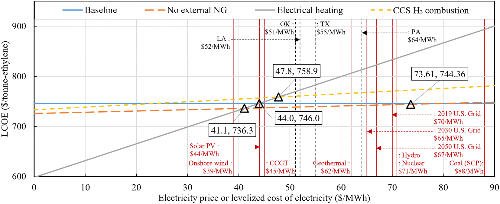
In grid electricity using scenario, contrary to the minimal TPC in the Electrical heating case, the LCOE is the highest. This is because the increase in costs due to external electricity usage dominates the contribution of capital costs reduction. Approximately 28.2% ($235 per tonne-ethylene) of the cost in this case is from electricity usage. Purge gas purification and external sales revenue (other credits) account for almost half of the cost increase due to external electricity imports, at $111.6 per tonne-ethylene. This suggests that internal purge gas recycling is a more effective strategy than purge gas purification and sales and external electricity importation strategy. In the same scenario, the LCOE of the CCS and H2 combustion case is approximately $28 per tonne-ethylene higher than that of the No external NG case. This is primarily influenced by the increase in LCOE due to increased electricity usage, at $20 per tonne-ethylene, while the capital cost's contribution increased by $7 per tonne-ethylene. This is mainly due to the increase in capital costs related to ATR, ASU, WGS, and CO2 capture. On the other hand, this modification achieves a reduction of 103 kgCO2e per tonne-ethylene in WTG GHG emissions. Based on these differences, compared to the No external NG case, the calculated CO2 avoidance cost of the CCS and H2 combustion case is $266 per tonCO2e.
In the renewable electricity scenario, the only difference from the grid scenario is the cost difference due to electricity use. Additionally, in the last two cases with different hydrogen prices, there is a difference in revenue due to hydrogen selling credits. The renewable electricity assumed in this study is based on the median levelized cost of electricity for a 100 MW-scale solar PV plant in the U.S., calculated by the International Energy Agency and the OECD Nuclear Energy Agency (NEA),67 at $44 per MW h. Additionally, the median power generation cost for U.S. wind onshore plants (>1 MW) is $39 per MW h, and for NG-based combined cycle gas turbine power plant, it is $45 per MW h, all showing similar range. Note that since electricity production costs, not prices, are used, this assumes that renewable electricity power generation modules are directly operated and managed within the ethylene production plants or accessed at near-cost prices. The grid electricity price is assumed to be $70 per MW h, so directly producing or accessing solar-based renewable electricity at cost levels ($44 per MW h) can reduce electricity usage costs by 37%. This reflects the situation in the U.S. where renewable energy is already competitively priced compared to fossil fuel or nuclear-based power. Consequently, the three decarbonized cases using renewable electricity show similar or lower ethylene production costs compared to the baseline case. The No external NG case had already shown cost parity with grid electricity usage instead of NG import, but with the additional cost reduction from using renewable electricity, it achieved $9 per tonne-ethylene savings compared to the Baseline case. Additionally, the Electrical heating case could result in a cost of $45 per tonne-ethylene to savings of $128 per tonne-ethylene compared to the Baseline case, depending on the hydrogen sale price ($0.5–3.0 per kg), respectively.
Fig. 11 shows the CO2 avoidance cost results based on the Baseline case, calculated using life cycle GHG emissions (Fig. 4) and LCOE (Fig. 10). Each case is clustered by different colors according to three hydrogen sale prices. The results showed that excluding the Electrical heating case, which export hydrogen, the two cases have same CO2 avoidance cost regardless of hydrogen price. A negative CO2 avoidance value indicates superiority in both cost and emissions, as both the LCOE cost, and WTG GHG emissions decrease from the Baseline case. All No External cases show negative CO2 avoidance costs, indicating superiority over conventional plants in both cost and emissions. In contrast, the Electrical heating cases substituting gray hydrogen using grid electricity yields a negative CO2 avoidance value in the low hydrogen price range due to increases in both the LCOE and WTG GHG emissions, indicating inferiority on both fronts, and thus it was not depicted in the figure. The Electrical heating cases show negative avoidance costs at hydrogen prices above $1.2 per kg-H2, and positive avoidance costs at lower hydrogen prices.
 | ||
| Fig. 11 CO2 avoidance cost results based on the Baseline case. | ||
As shown above, the LCOE results are affected by the price and cost assumptions for NG, electricity, and selling hydrogen. Consequently, the sensitivity analysis results are comprehensively provided as follows:
 | ||
| Fig. 12 Impact of natural gas price on LCOE of ethylene production. | ||
 | ||
| Fig. 13 Impact of electricity price on LCOE of ethylene production. | ||
 | ||
| Fig. 14 Impact of hydrogen price on LCOE of ethylene production. | ||
Policy-driven decarbonization pathways and economic support policies for ethylene production processes and by-products (C3+, hydrogen and methane), which may be introduced in the coming decades, can significantly influence the profitability of these approaches. Particularly, considering the attractive CO2 avoidance cost of the three ethylene decarbonization approaches, carbon credits could be considered to mitigate long-term price risks. Also, if the U.S. Inflation Reduction Act 45V clean hydrogen credit is applied to operators simultaneously producing and supplying both ethylene and hydrogen, a tax credit of $0.6–3.0 per kg-H2 can be granted depending on the hydrogen Tier (which translates to a $42–208 per tonne-ethylene LCOE reduction for the Electrical heating case). It is noteworthy that the Electrical heating case, one of the potential by-product hydrogen production system, includes a more complex variety of products and related sub-systems compared to blue and green hydrogen. Consequently, a market impact analysis and a consequential GHG reduction assessment in expanded system boundary are necessary to determine the inclusion of these processes under clean hydrogen title. This decision will heavily rely on the LCA approach68 that will be determined in the future.
3.4. Regional variance analysis
The single parameter sensitivity analysis above demonstrates the impact of CH4 emission rates, upstream emissions, and prices of NG, electricity, and substituted hydrogen on LCA and TEA results. However, uncertainties in these factors typically occur simultaneously in real-world scenarios and exhibit significant regional variability. To address this, this section analyzes scenarios where ethylene plants are located near various shale basins in the U.S. Each region assumes different upstream emissions and prices as detailed in Table 2 and below Table 6. The analysis encompasses both 2019 and 2030, with variations in electricity prices, upstream emissions, NG prices, and upstream emissions of substituted hydrogen applied for each year. For 2019, it is assumed that the co-produced hydrogen substitutes nearby gray hydrogen, while for 2030, substitutions are assumed to align with the U.S. roadmap:69 50% gray hydrogen, 25% blue hydrogen, and 25% green hydrogen.| Shale basins | State | Shale gas production share [%] | Electricity price [$ per MW h] | Industrial NG price [$ per GJ] | ||
|---|---|---|---|---|---|---|
| 2019 | 2030 | 2019 | 2030 | |||
| Anadarko | OK | 4.65% | 50.7 | 52.6 | 2.37 | 2.77 |
| Appalachian | PA | 51.88% | 64.1 | 55.5 | 8.07 | 3.81 |
| Arkla | LA | 7.51% | 52.3 | 52.6 | 3.19 | 2.77 |
| Arkoma | OK | 1.61% | 50.7 | 52.6 | 2.37 | 2.77 |
| East Texas | TX | 2.33% | 54.5 | 52.6 | 2.73 | 2.77 |
| Fort Worth Syncline | TX | 3.22% | 54.5 | 52.6 | 2.73 | 2.77 |
| Gulf Coast | TX | 11.81% | 54.5 | 52.6 | 2.73 | 2.77 |
| Permian | TX | 9.48% | 54.5 | 52.6 | 2.73 | 2.77 |
| South Oklahoma | OK | 1.79% | 50.7 | 52.6 | 2.37 | 2.77 |
| Strawn | TX | 5.72% | 54.5 | 52.6 | 2.73 | 2.77 |
| Total & weighted average | 100.00% | 59.0 | 54.1 | 5.51 | 3.31 | |
Fig. 15(a) illustrates the WTG GHG emissions of the four ethylene production processes for 2019 and 2030. In 2019, due to relatively high upstream emissions from grid electricity, the Electrical heating case exhibits the highest WTG GHG emissions across all regions. Among these, the Appalachian shale basin shows the lowest emissions, attributed to its low CH4 emission rate on production, gathering & boosting, and processing stages and low upstream emissions from electricity in the Pennsylvania. Across all regions, the CCS H2 combustion case exhibits the lowest emissions, reaffirming the reduction achieved through on-site emissions mitigation. In contrast, by 2030, the Electrical heating case demonstrates the lowest WTG GHG emissions in all regions, driven by the low carbonization of grid electricity projected for 2030. Consequently, the Baseline case shows the highest WTG GHG emissions across all regions, indicating that the three decarbonization strategies will serve as more robust tools for emissions reduction in the future compared to current conditions.
 | ||
| Fig. 15 Regional variance of (a) WTG GHG emission and (b) LCOE of the four cases for shale basins in U.S. | ||
Fig. 15(b) shows the LCOE results for the four cases in 2019 and 2030. Across all regions, in both years, the Electrical heating case exhibits the highest cost, followed by the CCS H2 combustion case, highlighting the continuing economic sensitivity of electricity-intensive processes to electricity prices. And across all regions, the No external NG and Baseline cases show almost identical LCOE values. The Appalachian shale basin emerges as the region with the highest LCOE due to its high current and future electricity and natural gas prices. Unlike the WTG GHG results, LCOE results display relatively low regional variability. This is because the most significant cost component—ethane feedstock price—is assumed to be constant across regions. As ethane prices typically fluctuate between NG and propane prices,55 incorporating NG price variability into feedstock ethane prices could make LCOE outcomes more sensitive to regional NG price differences. However, ethane price fluctuations do not alter the relative rankings among the four cases within individual regions, since they consume same amount of feedstock for unit product.
Taking a holistic view of WTG GHG emissions and LCOE, these findings suggest that, as the grid electricity continues to decarbonize, electrification of ethane crackers and the adoption of CCS technologies offer the greatest potential for cutting GHG emissions. However, given the projected high production costs, strategic policy measures—such as targeted subsidies for production or investment—could prove essential in accelerating the broad deployment of these cleaner technologies.
4. Conclusion
This study provides comprehensive TEA and LCA results for various decarbonization approaches in ethane steam cracker-based ethylene production processes. The Baseline case is a conventional ethane-based ethylene production process (with a capacity of 1 million tonnes per year) and three decarbonization approaches are as follows: (1) no external natural gas importation by importing electricity, (2) adoption of an electrically heated steam cracker with additional external electricity importation and resultant hydrogen and residual gas exportation, and (3) CCS application to internal purge gas. The study presents a comparative analysis of life cycle GHG emissions and LCOE, validating the results for the conventional case through comparison with previous research and providing novel insights into the decarbonization potential of the three unique cases examined. In addition, sensitivity analysis is conducted considering upstream GHG emissions of feedstock and fuel and CH4 emission rates from natural gas, as well as natural gas and electricity prices.For LCA, to assume upstream GHG emissions in the context of U.S. average, the emission values 8.213 kgCO2e per GJ for ethane, 12.211 kgCO2e per GJ for natural gas, are 439 kgCO2e per MW h for grid electricity are used. Across all cases, ethane's upstream GHG emissions accounted for nearly 50% of the WTG GHG emissions. The conventional plant exhibited a WTG GHG emission of 869 kgCO2e per tonne-ethylene, which align closely with previous studies’ results. Furthermore, the strategy of grid electricity importation to remove external natural gas usage has lower WTG GHG emissions of 806 kgCO2e per tonne-ethylene. When this strategy is combined with the utilization of renewable electricity, the emissions further reduced to 717 kgCO2e per tonne-ethylene. Electrically heated cracker plant showed 1031 kgCO2e per tonne-ethylene of emission. GHG credits obtained by purifying and selling hydrogen and purge gas (616 kgCO2e per tonne-ethylene) were smaller than the increase in grid electricity's upstream emissions (1106 kgCO2e per tonne-ethylene) resulting from the deficiency of fuel gas recycling. However, when this strategy is combined with the adoption of renewable electricity, the result is −163 kgCO2e per tonne-ethylene, which assumes the substitution of NG SMR-based gray hydrogen. When substituting NG ATR + CCS-based blue hydrogen and green hydrogen, the results are 137 and 380 kgCO2e per tonne-ethylene, respectively. The CCS application to purge gas case resulted in the lowest emissions of 703 kgCO2e per tonne-ethylene among all cases in grid electricity using cases due to the reduction of on-site emission. When this strategy is combined with the adoption of renewable electricity, the emissions further decreased to 514 kgCO2 per tonne-ethylene. In the case of substituting nearby gray hydrogen with co-produced hydrogen, the electrically heated case showed lower emissions than the conventional case when the upstream GHG emissions of electricity were below 380 kgCO2e per MW h. In the same substitution assumption, with upstream electricity emissions at 60 kgCO2e per MW h, the electrically heated cracker plant can achieve carbon neutrality. This implies that achieving carbon neutrality for all U.S. ethylene production processes using electrified steam crackers, approximately 12.2 GW of renewable electricity would be required.
For TEA, to assume fuel prices in the context of U.S. average, industrial grid electricity was priced at $70 per MW h and natural gas at $5 per GJ. Results showed that, when using grid electricity as electricity source, electrically heated cracker and adding CCS to purge gas case showed $833 and $771 per tonne-ethylene, respectively, both higher than conventional case's LCOE of $746 per tonne-ethylene, which also align closely with previous studies’ results. For the no external natural gas case exhibited the lowest LCOE of $743 per tonne-ethylene. When these plants introduce renewable power generation modules on-site or import electricity at a near-cost price of $44 per MW h, the LCOEs of the above three decarbonization cases were $746, $757, and $737 per tonne of ethylene, respectively. Below $41.1 per MW h of electricity price, the electrically heated cracker case proved advantage compared to all other cases. Between $41.1 and $73.6 per MW h, the case with substituting external gas to external electricity had the lowest LCOE, while above $73.6 per MW h, the conventional plant had the lowest LCOE. Additionally, the price of natural gas did not significantly influence the trends, except for the conventional case. In the range of natural gas prices below $4.1 per GJ, the conventional case was the most feasible, whereas above this threshold, the no external natural gas case demonstrated the highest advantage. Another highly sensitive factor was the price of hydrogen sold, which only showed sensitivity in the electrically heated cracker case where hydrogen export exists. Notably, in the scenario utilizing renewable electricity, as the price of hydrogen varied from $0.5 to $3.0 per kg-H2, the LCOE ranged from a cost of $45 per tonne-ethylene to savings of $128 per tonne-ethylene compared to the base conventional concept.
In order to capture variations across regions and address real-world uncertainties, a regional variance analysis was conducted. This analysis spans all U.S. shale gas basins and presents both current and future WTG GHG emissions as well as LCOE estimates.
This study holds a distinctive advantage in quantitatively comparing traditional ethylene production processes with promising decarbonization approaches. Our future work will focus on considering emerging decarbonization strategies or potentially robust ones not addressed in this study, such as oxidative coupling of methane technology and integration of flue gas CCS technology with ethylene production processes.
Author contributions
Woojae Shin: writing – original draft, investigation, formal analysis, writing – review & editing. Bosong Lin: investigation, writing – review & editing. Haoxiang Lai: investigation, formal analysis, writing – review & editing. Gasim Ibrahim: investigation, writing – review & editing. Guiyan Zang: conceptualization, methodology, investigation, formal analysis, writing – review & editing, supervision.Data availability
The data supporting this article have been included as part of the ESI.†Conflicts of interest
The authors have no competing financial interests or personal relationships that could have appeared to influence the work reported in this paper.Acknowledgements
The authors would like to thank the financial support from the MIT Energy Initiative (MITEI) Future Energy Systems Center for the project “Atoms-to-enterprise analysis for decarbonization of chemical manufacturing – case study of ethylene”. We would also like to extend our thanks to professor William H. Green and Julian Ufert of MIT Green Research Group for their insightful discussion and feedback.References
- Intergovernmental Panel on Climate Change, Mitigation of Climate Change, 2022 Search PubMed.
- E. G. Rightor and C. L. Tway, Catal. Today, 2015, 258, 226–229 CrossRef CAS.
- IEA, Technology Roadmap - Energy and GHG Reductions in the Chemical Industry via Catalytic Processes, Paris, 2013 Search PubMed.
- C. A. Gärtner, A. C. van Veen and J. A. Lercher, ChemCatChem, 2013, 5, 3196–3217 Search PubMed.
- Statista, Production capacity of ethylene worldwide from 2018 to 2022, 2023 Search PubMed.
- Statista, Market size of ethylene worldwide in 2021, with a forecast until 2030, 2021 Search PubMed.
- Global Data, Ethylene Capacity and Capital Expenditure Outlook by Region, Countries, Companies, Feedstock, Projects and Forecast to 2030, 2023 Search PubMed.
- Y. Gao, L. Neal, D. Ding, W. Wu, C. Baroi, A. M. Gaffney and F. Li, ACS Catal., 2019, 9, 8592–8621 CrossRef CAS.
- E. Worrell, D. Phylipsen, D. Einstein and N. Martin, Energy use and energy intensity of the US chemical industry, 2000 Search PubMed.
- F. A. Atiku, V. Pirouzfar, C.-H. Su and S.-Y. Wei, Int. J. Chem. React. Eng., 2021, 19, 415–425 CrossRef CAS.
- A. Chauvel and G. Lefebvre, Synthesis-gas derivatives and major hydrocarbons, 1989 Search PubMed.
- H. Zimmermann and R. Walzl, in Ullmann's Encyclopedia of Industrial Chemistry, 2009, DOI:10.1002/14356007.a10_045.pub3.
- T. Ren, M. Patel and K. Blok, Energy, 2006, 31, 425–451 CrossRef CAS.
- M. Ghanta, D. Fahey and B. Subramaniam, Appl. Petrochem. Res., 2014, 4, 167–179 CrossRef CAS.
- B. Young, T. R. Hawkins, C. Chiquelin, P. Sun, U. R. Gracida-Alvarez and A. Elgowainy, J. Cleaner Prod., 2022, 359, 131884 CrossRef CAS.
- J. L. Tiggeloven, A. P. Faaij, G. J. Kramer and M. Gazzani, Ind. Eng. Chem. Res., 2023, 62, 16360–16382 CrossRef CAS.
- P. Haro, P. Ollero and F. Trippe, Fuel Process. Technol., 2013, 114, 35–48 CrossRef CAS.
- Y. K. Salkuyeh and T. A. Adams II, Energy Convers. Manage., 2015, 92, 406–420 CrossRef.
- L. S. Layritz, I. Dolganova, M. Finkbeiner, G. Luderer, A. T. Penteado, F. Ueckerdt and J.-U. Repke, Appl. Energy, 2021, 296, 117049 CrossRef CAS.
- R. Chauhan, R. Sartape, N. Minocha, I. Goyal and M. R. Singh, Energy Fuels, 2023, 37, 12589–12622 CrossRef CAS.
- Y. Chen, M. J. Kuo, R. Lobo and M. Ierapetritou, Green Chem., 2024, 26, 2903–2911 RSC.
- A. Boulamanti and J. A. Moya, Renewable Sustainable Energy Rev., 2017, 68, 1205–1212 CrossRef CAS.
- H. Hu, D. Ding, L. T. Knighton, D. S. Wendt and R. D. Boardman, Techno-economic analysis on an electrochemical non-oxidative deprotonation process for ethylene production from Ethane, Idaho National Lab.(INL), Idaho Falls, ID (United States), 2019 Search PubMed.
- A. H. Nyhus, M. Yliruka, N. Shah and B. Chachuat, Energy Environ. Sci., 2024, 17, 1931–1949 RSC.
- G. Zang, E. J. Graham and D. Mallapragada, Int. J. Hydrogen Energy, 2024, 49, 1288–1303 CrossRef CAS.
- D.-Y. Lee and A. Elgowainy, Int. J. Hydrogen Energy, 2018, 43, 20143–20160 CrossRef CAS.
- X. Liu, A. Elgowainy and M. Wang, Green Chem., 2020, 22, 5751–5761 RSC.
- K. Lee, X. Liu, P. Vyawahare, P. Sun, A. Elgowainy and M. Wang, Green Chem., 2022, 24, 4830–4844 RSC.
- Global Data, China and US lead global ethylene capacity additions by 2026, says GlobalData, 2019 Search PubMed.
- M. Ali, L. Zu-Wei, Y. Yao, S. Jing-Yuan, J. Bin-Bo, W. Jing-Dai and Y. Yong-Rong, China Pet. Process. Petrochem. Technol., 2020, 22, 117 CAS.
- P. Ranjan, P. Kannan, A. Al Shoaibi and C. Srinivasakannan, Chem. Eng. Technol., 2012, 35, 1093–1097 CrossRef CAS.
- D. Y. Caballero, L. T. Biegler and R. Guirardello, in Computer Aided Chemical Engineering, Elsevier, 2015, vol. 37, pp. 917–922 Search PubMed.
- P. Thiruvenkataswamy, F. T. Eljack, N. Roy, M. S. Mannan and M. M. El-Halwagi, J. Loss Prev. Process Ind., 2016, 39, 74–84 CrossRef CAS.
- M. Rosli and N. Aziz, IOP Conference Series: Materials Science and Engineering, 2016, 162, 012017.
- C. Ogundipe, Simulation and Sustainability Analysis of the Methanol to Olefins (MTO) and Steam Cracking of Ethane Processes for Ethylene Production, Texas A&M University, Kingsville, 2020 Search PubMed.
- M. Yang and F. You, Chem. Eng. Trans., 2017, 61, 1561–1566 Search PubMed.
- M. Yang and F. You, Ind. Eng. Chem. Res., 2017, 56, 4038–4051 CrossRef CAS.
- G. J. Maffia, A. M. Gaffney and O. M. Mason, Top. Catal., 2016, 59, 1573–1579 Search PubMed.
- Y. Yao, D. J. Graziano, M. Riddle, J. Cresko and E. Masanet, Environ. Sci. Technol., 2015, 49, 14704–14716 CrossRef CAS PubMed.
- E. Energetics, Environmental Profile of the US Chemical industry—Chapter 4, 2000 Search PubMed.
- BASF, BASF, SABIC, and Linde celebrate the start-up of the world's first large-scale electrically heated steam cracking furnace, 2024 Search PubMed.
- H. Son, M. Kim and J.-K. Kim, Energy, 2022, 239, 122060 CrossRef.
- The Dow Chemical Company, Dow announces plan to build world's first net-zero carbon emissions ethylene and derivatives complex, 2021 Search PubMed.
- M. Wang, A. Elgowainy, U. Lee, A. Bafana, S. Banerjee, P. T. Benavides, P. Bobba, A. Burnham, H. Cai and U. R. Gracida-Alvarez, Summary of Expansions and Updates in GREET® 2021, Argonne National Lab.(ANL), Argonne, IL (United States), 2021 Search PubMed.
- J. Littlefield, D. Augustine, A. Pegallapati, G. G. Zaimes, S. Rai and G. Cooney, Life cycle analysis of natural gas extraction and power generation, National Energy Technology Laboratory (NETL), Pittsburgh, PA, Morgantown, WV, 2019 Search PubMed.
- EIA, U.S. ethane production, consumption, and exports set new records again in 2023, 2024 Search PubMed.
- M. Penev, G. Saur, C. Hunter and J. Zuboy, User Guide i, US Department of Energy, United States of America, 2018 Search PubMed.
- R. Davis, L. Tao, E. Tan, M. Biddy, G. Beckham, C. Scarlata, J. Jacobson, K. Cafferty, J. Ross and J. Lukas, Process design and economics for the conversion of lignocellulosic biomass to hydrocarbons: dilute-acid and enzymatic deconstruction of biomass to sugars and biological conversion of sugars to hydrocarbons, National Renewable Energy Lab.(NREL), Golden, CO (United States), 2013 Search PubMed.
- P. Spath, A. Aden, T. Eggeman, M. Ringer, B. Wallace and J. Jechura, Biomass to hydrogen production detailed design and economics utilizing the Battelle Columbus Laboratory indirectly-heated gasifier, National Renewable Energy Lab.(NREL), Golden, CO (United States), 2005 Search PubMed.
- R. M. Swanson, A. Platon, J. Satrio, R. Brown and D. D. Hsu, Techno-economic analysis of biofuels production based on gasification, National Renewable Energy Lab.(NREL), Golden, CO (United States), 2010 Search PubMed.
- E. Lewis, S. McNaul, M. Jamieson, M. S. Henriksen, H. S. Matthews, L. Walsh, J. Grove, T. Shultz, T. J. Skone and R. Stevens, Comparison of commercial, state-of-the-art, fossil-based hydrogen production technologies, National Energy Technology Laboratory (NETL), Pittsburgh, PA, Morgantown, WV, 2022 Search PubMed.
- A. Zoelle, D. Keairns, L. L. Pinkerton, M. J. Turner, M. Woods, N. Kuehn, V. Shah and V. Chou, Cost and performance baseline for fossil energy plants volume 1a: bituminous coal (PC) and natural gas to electricity revision 3, National Energy Technology Laboratory (NETL), Pittsburgh, PA, Morgantown, WV, 2015 Search PubMed.
- S. B. Jones, C. Valkenburt, C. W. Walton, D. C. Elliott, J. E. Holladay, D. J. Stevens, C. Kinchin and S. Czernik, Production of gasoline and diesel from biomass via fast pyrolysis, hydrotreating and hydrocracking: a design case, Pacific Northwest National Lab.(PNNL), Richland, WA (United States), 2009 Search PubMed.
- Intratec Solutions, Ethane Prices | Current and Forecast, https://www.intratec.us/chemical-markets/ethane-price.
- EIA, Hydrocarbon gas liquids explained - Prices for hydrocarbon gas liquids, 2024 Search PubMed.
- EIA, Natural Gas Prices, https://www.eia.gov/dnav/ng/NG_PRI_SUM_A_EPG0_PIN_DMCF_A.htm.
- K. Gerdes, W. M. Summers and J. Wimer, Quality Guidelines for Energy System Studies: Cost Estimation Methodology for NETL Assessments of Power Plant Performance, National Energy Technology Laboratory (NETL), Pittsburgh, PA, Morgantown, WV, 2011 Search PubMed.
- EIA, Average retail price of electricity to ultimate customers, https://www.eia.gov/electricity/data.php#sales.
- LPG Price Monitoring Agency, Butane in United States, https://lpg-price.com/butane/united-states.html.
- H. Murdoch, J. Munster, S. Satyapal, N. Rustagi, A. Elgowahy and M. Penev, Pathways to Commercial Liftoff, Clean Hydrogen, US Department of Energy, 2023 Search PubMed.
- K. Tanaka, Assessing measures of energy efficiency performance and their application in industry, 2008 Search PubMed.
- U. Lee, J. Han and M. Wang, Well-to-Wheels Analysis of Compressed Natural Gas and Ethanol from Municipal Solid Waste, Argonne National Lab.(ANL), Argonne, IL (United States), 2016 Search PubMed.
- U. Lee, J. Han and M. Wang, J. Cleaner Prod., 2017, 166, 335–342 CrossRef CAS.
- EIA, Annual energy outlook 2023 (AEO2023), 2023 Search PubMed.
- EIA, U.S. ethane production to grow, along with expanding domestic consumption and exports, https://www.eia.gov/todayinenergy/detail.php?id=48056.
- Statista, Price of ethylene worldwide from 2017 to 2022, https://www.statista.com/statistics/1170573/price-ethylene-forecast-globally/.
- IEA, Projected costs of generating electricity 2020, 2020 Search PubMed.
- US Department of Energy, Guidelines to Determine Well-to-Gate Greenhouse Gas (GHG) Emissions of Hydrogen Production Pathways using 45VH2-GREET 2023, 2023 Search PubMed.
- US Department of Energy, US National Clean Hydrogen Strategy and Roadmap, 2023 Search PubMed.
Footnote |
| † Electronic supplementary information (ESI) available: Detailed process configuration (Fig. S1 and S12), allocation methodologies (Fig. S13–S16), stream information (Tables S1–S4), kinetic reaction (Table S5), equipment costs (Tables S6–S9), and financial assumption (Table S10). See DOI: https://doi.org/10.1039/d4gc04538f |
| This journal is © The Royal Society of Chemistry 2025 |