 Open Access Article
 This Open Access Article is licensed under a
 Creative Commons Attribution 3.0 Unported Licence
Unveiling the structure of protein-based hydrogels by overcoming cryo-SEM sample preparation challenges†
Dimitra
Katrantzi
 *a,
Stuart
Micklethwaite
a,
Nicole
Hondow
a,
Andy
Brown
a and
Lorna
Dougan
*b
*a,
Stuart
Micklethwaite
a,
Nicole
Hondow
a,
Andy
Brown
a and
Lorna
Dougan
*b
aSchool of Chemical and Process Engineering, Faculty of Engineering and Physical Sciences, University of Leeds, UK. E-mail: pmdka@leeds.ac.uk
bSchool of Physics and Astronomy, Faculty of Engineering and Physical Sciences, University of Leeds, UK. E-mail: L.Dougan@leeds.ac.uk
First published on 29th January 2025
Abstract
Protein-based hydrogels have gained significant attention for their potential use in applications such as drug delivery and tissue engineering. Their internal structure is complex, spans across multiple length scales and affects their functionality, yet is not well understood because of folded proteins’ sensitivity to physical and chemical perturbations and the high water content of hydrogels. Cryo-scanning electron microscopy (cryo-SEM) has the potential to reveal such hierarchical structure when hydrated hydrogels are prepared with appropriate cryofixation. We show for photochemically cross-linked, folded globular bovine serum albumin (BSA) protein hydrogels that preparation artefacts are reduced by in situ gelation, high pressure freezing (HPF), plasma focused ion beam (pFIB) milling, sublimation, and low dose secondary electron imaging. Cryo-SEM of folded BSA protein hydrogels prepared in this way reveals a heterogeneous network with nanoscale porosity (∼60 nm pores) surrounded by high secondary electron emission regions (∼30 nm diameter) interconnected by narrower, lower emission regions (∼20 nm length). This heterogeneous network structure is consistent with small angle scattering studies of folded protein hydrogels, with fractal-like clusters connected by intercluster regions. We further test the potential of cryo-SEM to detect the impact of protein unfolding on hydrogel network formation and reveal nanoscale differences in cluster sizes consistent with those derived from scattering data. Importantly, cryo-SEM directly images pores for sizing in both systems, with initial results on BSA suggesting protein unfolding induces an increase of ∼10 nm in pore sizes. Our findings on cryo-SEM sample preparation challenges and solutions provide new opportunities to link hydrogel structure to function.
Introduction
Hydrogels are three-dimensional, hydrated, highly porous, percolating biopolymer networks spanning macroscopic dimensions. Hydrogels display rich viscoelastic properties, including mechanical strength and stress relaxation, and have hierarchical structures which span the nanoscale properties of the building blocks to the mesoscale of the cross-linked network structure.1–3 The space within the hydrogel is critical to function, including the pore size between the cross-linked networks, since this can be exploited for a range of functions, including small molecule loading and release.4–8 Morphological studies to accurately measure and understand the mesoscale structure of hydrogels are therefore important for exploiting hydrogels as biomaterials in applications such as medicine and healthcare.8,9The most common techniques used to characterise the structure and morphology of supramolecular gels are scattering and microscopy.10,11 Whilst both approaches offer valuable information on hydrogel properties, they each have well-recognised challenges and limitations. As a result, an integrated approach is required to gain robust and meaningful insight into the structure of hydrogels.12 Small angle scattering (SAS) techniques, including small angle X-ray scattering (SAXS) and small angle neutron scattering (SANS), are powerful tools for the in situ bulk characterisation of the gels, probing size, shape, internal structure and spatial arrangement on length scales between 0.25 and 300 nm, that require model fitting to extract real space information from the scattering q-space.13,14 Microscopy techniques have the advantage of acquisition of real-space structures. However, they often require sample preparation, which can be prone to artefacts and only provide information about the local structure, requiring averaging to obtain a bulk overview.15
Recently, super-resolution microscopy has been employed for morphological studies of hydrogels providing measurements by automated approaches, but faced challenges such as biased image processing and lower resolution than electron microscopy (EM).16 There has been a long tradition of more than twenty years of using EM in an attempt to gain structural information on supramolecular gels.17–21 Scanning electron microscopy (SEM) is widely used for imaging the architecture of materials across different length scales due to its high resolution (typically 1–10 nm).22,23 SEM operates under high vacuum, which causes water evaporation and, therefore, requires drying of hydrated samples before imaging, which will cause structural alteration via shrinkage.24–27 Alternatively, cryo-SEM prohibits sample dehydration during imaging by examining a frozen sample at cryogenic temperatures.28
Cryofixation is the most critical step for cryo-SEM, as an insufficient freezing rate results in ice crystal formation.29 Ice crystals alter the sample structure because solutes are rejected to the boundaries of growing ice crystals, forming a segregation pattern determined by the cooling rate.30,31 By freezing at high cooling rates (i.e. very rapidly), water molecules are immobilised and remain in a non-crystalline state, resulting in a glass-like solid called vitreous (amorphous) ice.32,33 The cooling rate influences both nucleation and growth rates of crystalline ice, with slow cooling at ambient pressure, permitting formation of hexagonal ice, faster cooling producing cubic ice and only very rapid cooling inhibiting ice nucleation and vitrifying the water.33 In an ideally cryo-immobilised sample, all water is vitrified, and solutes remain in their native/original environment.34,35 The commonly used bulk cryofixation methods are slush/liquid nitrogen freezing and high pressure freezing (HPF).
Freezing with liquid nitrogen consists of immersing a sample into a slush of liquid nitrogen (a mixture of solid and liquid) and is a widely used cryofixation method for hydrogels that results in the formation of a characteristic honeycomb-like gel structure.36–44 This technique, however, has a slow freezing rate (around 500 K s−1) and is only ideal for samples with a thickness of less than 2–5 μm.30,45 HPF, on the other hand, has a larger thickness limit for the formation of vitreous ice because the sample is secured and frozen in liquid nitrogen under high pressure (2045 bar). Pressure lowers the crystalline ice nucleation temperature and inhibits expansion on crystallisation.46 At ambient pressures, several 100![[thin space (1/6-em)]](https://www.rsc.org/images/entities/char_2009.gif) 000 K s−1 are required to vitrify a eukaryotic cell, whereas only a few 1000 K s−1 will be enough at 2045 bars.47 The upper thickness limit for complete vitrification of a sample in HPF is 200–500 μm.47,48 HPF is now considered the cryofixation method to effectively cryoimmobilise cellular samples without morphological changes, and there are examples of wider application to other systems, including hydrogels.49,50 Given this and the developments in cryo-SEM, consideration should be given to their application to the full range of hydrogel materials, including emerging areas such as folded protein-based hydrogels.1,8,9
000 K s−1 are required to vitrify a eukaryotic cell, whereas only a few 1000 K s−1 will be enough at 2045 bars.47 The upper thickness limit for complete vitrification of a sample in HPF is 200–500 μm.47,48 HPF is now considered the cryofixation method to effectively cryoimmobilise cellular samples without morphological changes, and there are examples of wider application to other systems, including hydrogels.49,50 Given this and the developments in cryo-SEM, consideration should be given to their application to the full range of hydrogel materials, including emerging areas such as folded protein-based hydrogels.1,8,9
In recent years, folded proteins have emerged as promising building blocks for constructing hydrogels. While studies have employed thermal or pH-induced denaturation of proteins to trigger gelation through physical cross-links,51–54 there is a growing interest in retaining the fold of the protein to preserve its function in the hydrogel material. A pioneering study by Li et al. engineered a protein hydrogel aimed to mimic the mechanical properties of the giant muscle protein titin.55 Further studies have engineered protein hydrogels mimicking the mechanical properties of tissues, forming highly elastic and stimuli-responsive materials, and dynamically regulating their properties and shape.37,56–66 Engineering of natural and synthetic proteins has enabled the formation of hydrogels with programmable properties.1,67,68 However, it remains challenging to understand how the nanoscale protein structure and mechanics translate to the macroscopic properties of the hydrogel network. Given the sensitivity of proteins to physical and chemical perturbations, there is enormous potential in exploiting protein unfolding to modulate the dynamic properties of protein hydrogels. Indeed, it has become clear that protein unfolding is critical to network mechanics and the architecture of protein hydrogels.69–71
In particular, recent studies have highlighted the role of in situ unfolding and entanglement in defining hydrogel network mechanics.70,72,73 For example, using bovine serum albumin (BSA) as a model protein, an integrated SANS and rheology analysis showed that in situ unfolding altered network topology and enhanced network mechanical rigidity.70 More recently, protein unfolding has been exploited in a protein–polymer system that undergoes a unique strain stiffening and strengthening behaviour after shape recovery cycles.71 Such control of in situ unfolding provides a powerful route for the design of tuneable biomaterials for medical and healthcare applications.8,72 Given their potential, there is an urgent need to develop robust experimental methods to study the structure of protein hydrogels to determine and understand the impact of protein unfolding on the network structure and morphology. Here, we focus on the application of cryo-SEM for structural analyses of protein hydrogels.
For this purpose, the BSA protein was used as the building block to create protein-based hydrogels. BSA is a globular folded protein with attractive properties such as biodegradability, biocompatibility, low cost, non-immunogenicity, and drug binding capabilities, enhancing the properties of hydrogels when used as the building block.74–76 The folded state of BSA is held together by 17 covalent disulphide bonds, which act as ‘nanostaples’ and stay intact during gelation (Fig. 1). These mechanically robust covalent staples can withstand forces as high as 2 nN,77,78 far exceeding the 20–100 pN generated within the cross-linked protein network.79 Moreover, these bonds can be removed by reducing agents such as dithiothreitol (DTT), making the protein force labile, allowing it to easily unfold under the forces generated during gelation. Together, these properties render BSA an ideal model for protein unfolding studies. For gelation, a photochemical crosslinking method is used, during which the solvent accessible surface tyrosine residues of BSA (Fig. 1) crosslink with neighbouring BSA molecules by irreversible dityrosine bonding.80 A schematic showing the photochemical crosslinking of a folded (mechanically robust) BSA to form a hydrogel is shown in Fig. 1. Finally, we test this protocol on unfolded protein-based hydrogels composed of force labile BSA protein to detect morphological alterations to the gel network. Linking the cryo-SEM protocols and analysis methods we present to SAS models opens the possibility of complete structure–property evaluation of hydrogels in general.70 The rheology of the final folded protein-based hydrogel is explored using a parallel plate geometry to confirm successful gelation. Previous SANS and SAXS studies have shown that the final BSA protein network consists of fractal-like clusters of proteins connected by intercluster regions of folded proteins (Fig. 1).2,70,73,81–83
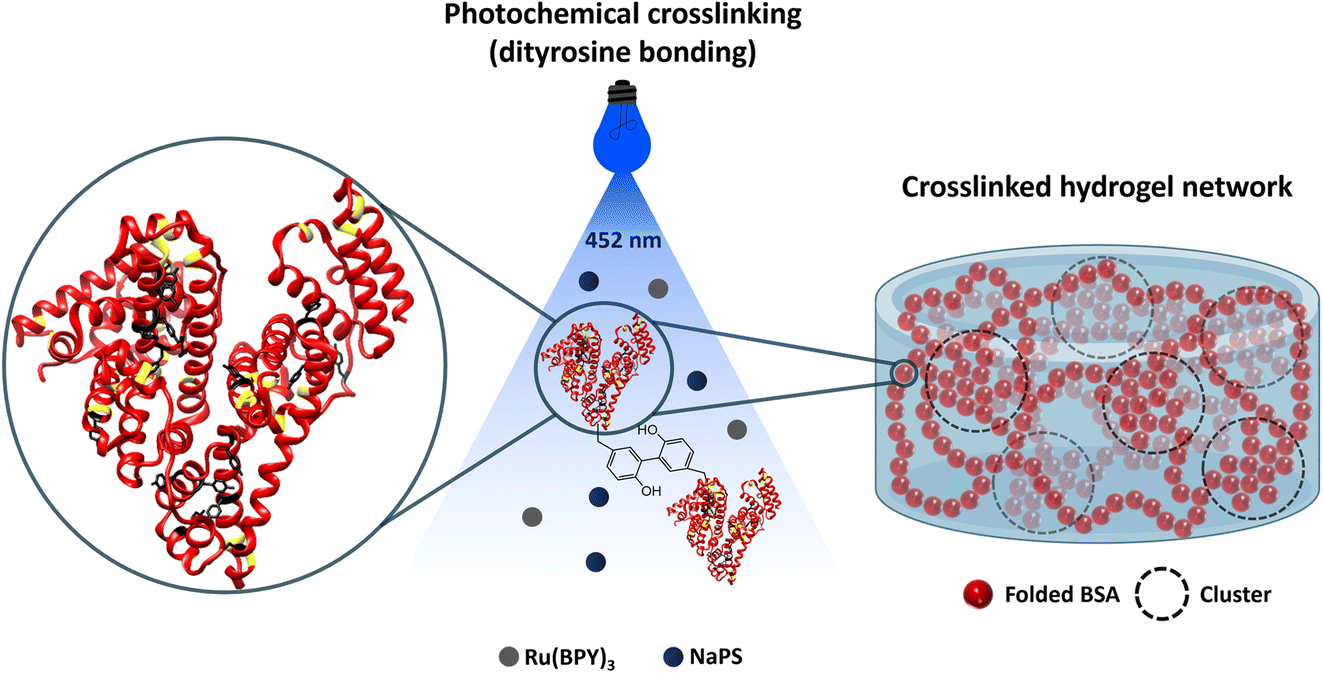 | ||
| Fig. 1 Schematic of folded BSA-based hydrogel synthesis by a Ru(BiPy)3 catalysed photochemical crosslinking method (BSA PDB code: 3V03). Disulphide bonds are highlighted with yellow, and tyrosine residues with black. The mechanically robust disulphide bonds hold the folded state of BSA together and stay intact during gelation. The tyrosine residues are used for the crosslinking to form the hydrogel. In the presence of light, Ru(BiPy)3 photo-oxidizes to Ru(BiPy)33+, and NaPS acts as an electron acceptor. The photoactivated Ru(BiPy)3 extracts an electron from tyrosine, leading to tyrosine radical species that can covalently crosslink via dityrosine bonding, highlighted in the middle schematic, to form the hydrogel. The crosslinked hydrogel network schematic constructed by SAXS and SANS data70 represents the BSA hydrogel network. The network consists of fractal-like clusters (dashed circles) made of folded proteins connected by more sparsely populated intercluster regions of folded proteins. | ||
In this study, we develop a reproducible protocol for representative preparation and cryo-SEM imaging of folded protein-based hydrogels while identifying structural artefacts induced by ice crystallisation. We benchmark features of the vitrified gel network against those obtained by SAS analysis2,70,73,81–83 and evaluate additional aspects of the morphology of these gels, such as pore sizes. Finally, we test this protocol on unfolded protein-based hydrogels composed of force labile BSA protein to detect morphological alterations to the gel network. Linking the cryo-SEM protocols and analysis methods we present to SAS models opens the possibility of complete structure–property evaluation of hydrogels in general.
Experimental
Materials
Bovine serum albumin (heat shock fraction, protease free and essentially globulin free), sodium persulfate (NaPS), tris(2,2′-bipyridyl)dichlororuthenium(II) hexahydrate (Ru(BiPy)3), 1,4-dithiothreitol (DTT), sodium phosphate monobasic and sodium phosphate dibasic were purchased from Sigma-Aldrich and used without further treatment.Hydrogel preparation
As previously described,2,70,81,83 initially, a protein stock of 200 mg per mL BSA and a cross-link reagent stock of 100 mM NaPS and 200 μM Ru(BiPy)3 are prepared. For the unfolded protein gels, 6 mM DTT is also prepared for the reagent stock. Hydrogel samples are prepared by mixing in a 1:1 mass ratio of protein stock to cross-link reagent stock to obtain final concentrations of 100 mg per mL BSA, 50 mM NaPS, 100 μM Ru(BiPy)3, and 3 mM DTT.
Rheology
Rheology was performed to characterise the mechanical properties of the hydrogels in situ by an Anton Paar MCR 302 rheometer using a parallel plate geometry (8 mm diameter). The pre-gel solution was loaded on the rheometer, and the gap height was adjusted for each measurement to ensure correct sample filling. Then, a thin layer of silicon oil was pipetted at the edges of the pre-gel solution to avoid any sample evaporation. Measurements were carried out at 20 °C. A blue LED light source operating at a current of 0.48 A, was turned on, initiating gelation (by photochemical crosslinking)70,80 and was turned off after 5 min, completing gelation. Time sweep (oscillation) experiments were performed at a constant frequency of 1 Hz and a shear strain of 0.5%. The measurements continued for 60 min after the lamp was turned off to record relaxation of the samples post-gelation. Frequency sweep measurements were acquired over the range of 0.1 to 2 Hz. Following the method described by Hughes et al., the relaxation exponent n is extracted by fitting a linear function to the frequency sweeps:70| log(G′) = nlog(f) + log(A) | (1) |
Cryo-SEM sample preparation
Cryo-SEM imaging
The structural features of the hydrogels were plasma focused ion beam (pFIB) milled and imaged at cryogenic temperatures using a TESCAN AMBER X Plasma FIB-SEM. The frozen hydrogels were transferred onto a cooled specimen stage held at −140 °C inside a Quorum cryo-preparation chamber under high vacuum (10−7 mbar). An anti-contaminator was cooled to −170 °C to reduce frost contamination. The slush frozen hydrogels were fractured using a cold knife and sublimed at −70 °C for 5 min to expose the internal features of the gels and then vacuum transferred into the imaging chamber of the SEM. In an alternative route to expose the inner structure of the HPF hydrogels, pFIB milling with a 10 nA probe was conducted to mill a 30 × 30 × 20 μm (width × height × depth) volume of sample (microscope details are given below). The front side of the milled trench was further polished using a 1 nA pFIB probe to reveal an unaltered face of pristine gel. Then, the HPF samples were sublimed at −100 °C for 8 min to expose the pores of the hydrogels. All samples were surface sputter-coated with platinum at 5 mA for 45 s to enhance their conductivity and reduce thermal damage and charging. The samples were transferred inside the SEM chamber under high vacuum at −140 °C. Images were taken at a range of magnifications with a probe current of 100 pA and beam energy of 2 kV (to minimise irradiation damage). Elemental mapping of hydrated sample surfaces was conducted using an Oxford Instruments Aztec Energy Dispersive X-ray (EDX) Spectroscopy system.Image analysis
The ImageJ software,84 was used for pore size, wall thickness, cluster size and intercluster distance analysis. Image segmentation was conducted for the pore size measurements. In detail, a contrast threshold is set at around 35–45%, depending on the contrast of the image pre-processing, to put background signal (i.e. pores) to black and preserve only morphological information as white. After that, ‘watershed’ and ‘fill holes’ analysis tools are selected to automatically separate and cut ‘particles’ that touch and fill any remaining holes that could affect the measurements. The Feret's diameter was assigned for the pore length. Pores caused due to beam damage were excluded from the measurements (Fig. S1† shows an increase in pore sizes due to prolonged exposure by the electron beam). For visualisation of the protein clusters and intercluster distances, enhanced contrast images were obtained by narrowing the contrast and brightness limits of the image to reveal signal from the front layer of the sample. Standard errors are used, and data are shown by mean ± standard error of the mean.Results and discussion
Rheology of folded protein hydrogels
In order to confirm successful gelation of BSA hydrogels, elastic (storage) (G′) and viscous (loss) (G′′) moduli were measured against time in situ (Fig. 2a). A time sweep monitoring the gelation of a photochemically cross-linked 7.4% (volume fraction) folded BSA hydrogel is displayed in Fig. 2b. This time sweep behaviour has previously been reported for in situ gelation studies on folded BSA gels.70,73,81–83 The gelation curve shows the evolution of G′ and G′′ with time when a lamp is switched on at t = 0 s, initiating gelation, switched off at t = 300 s, completing gelation, and during network relaxation up to t = 3960 s. Initially, a sharp increase in G′ is displayed due to photo-activated crosslinking gelation of the BSA protein into a network, which then decreases due to network relaxation, reaching a time-stable plateau value. The time at which G′ = G′′ (t = 21 s) indicates the gelation point as the sample transitions into a viscoelastic gel. | ||
| Fig. 2 (a) Schematic of sample preparation, parallel plate geometry and measurements for the folded BSA (7.4% BSA) hydrogel rheology. The pre-gelled sample is placed on top of a glass surface, and blue light illumination from below is used for photoactivated gelation. (b) Time sweep rheology measurements confirm successful gelation. Gelation curves showing the changes in the elastic G′ and viscous G′′ moduli against time at 1 Hz. At t = 0 s, the lamp is turned on, initiating gelation. After 300 s, the lamp is turned off, completing gelation (highlighted by blue light). The measurements were done in real time, monitoring the formation and relaxation behaviour of the hydrogel. (c) Frequency sweep measurements of G′, G′′ and (d) the loss ratio, tan(δ) of the photochemically crosslinked gels. Filled symbols represent the storage modulus (G′), and the open symbols the loss modulus (G′′). The error ribbons (b) and bars (c and d) display the standard errors calculated after 3 repeats. | ||
The frequency sweeps displayed in Fig. 2c and d show G′, G′′ and the loss ratio tan(δ) (defined as G′′/G′) variation versus oscillation frequency. Both elastic and viscous components increase with increased frequency. Fitting a linear function to the G′ data of Fig. 2c, between 0.1 and 2 Hz, enables a relaxation exponent n to be calculated.70 We measured n for the folded BSA hydrogels to be 0.029 ± 0.0002, indicating that the gels have elastically dominated behaviour (n for a viscous hydrogel approaches 1, whereas that of an elastic hydrogel approaches 0). This is also supported by the loss ratio tan(δ), which has a value below 0.1 (tan(δ) is defined as G′′/G′, so when tan(δ) is below 1, the gel exhibits elastically dominated solid-like behaviour, whereas, when tan(δ) is higher than 1, the gel displays a liquid-like behaviour).
Small angle scattering (SAS) reveals mesoscale structure for complementing cryo-SEM
Small angle neutron scattering (SANS) and small angle X-ray scattering (SAXS) are used to probe network structure on length scales between tens to hundreds of Angstroms to study the structure of hydrogels,14 including photochemically cross-linked protein hydrogels. SAS provides the opportunity to extract in situ bulk measurements of a system (Fig. 3a). The data shown in Fig. 3b and c show SAXS and SANS for folded BSA hydrogels (7.4% BSA) prepared in the same way as the present study.70 The SANS experiments were completed in a 35% D2O/65% H2O solution, while the SAXS experiments for folded BSA hydrogels (Fig. 3a and c) were completed in the Nano-inXider instrument at the ISIS neutron and Muon Source (concentration: 7.4% BSA, 20 mM NaPS, 100 μM Ru(BiPy)3 in 100% H2O).70 Differences are observed in the background scattering in the SANS data compared to the SAXS data, as expected, due to the higher incoherent scattering from the hydrogen in the buffer in SANS which is not a consideration in SAXS. SANS and SAXS experiments have previously shown that these folded BSA hydrogels form heterogeneous network structures with fractal-like clusters connected by more sparsely populated intercluster regions of folded proteins (Fig. 3d).70,81–83.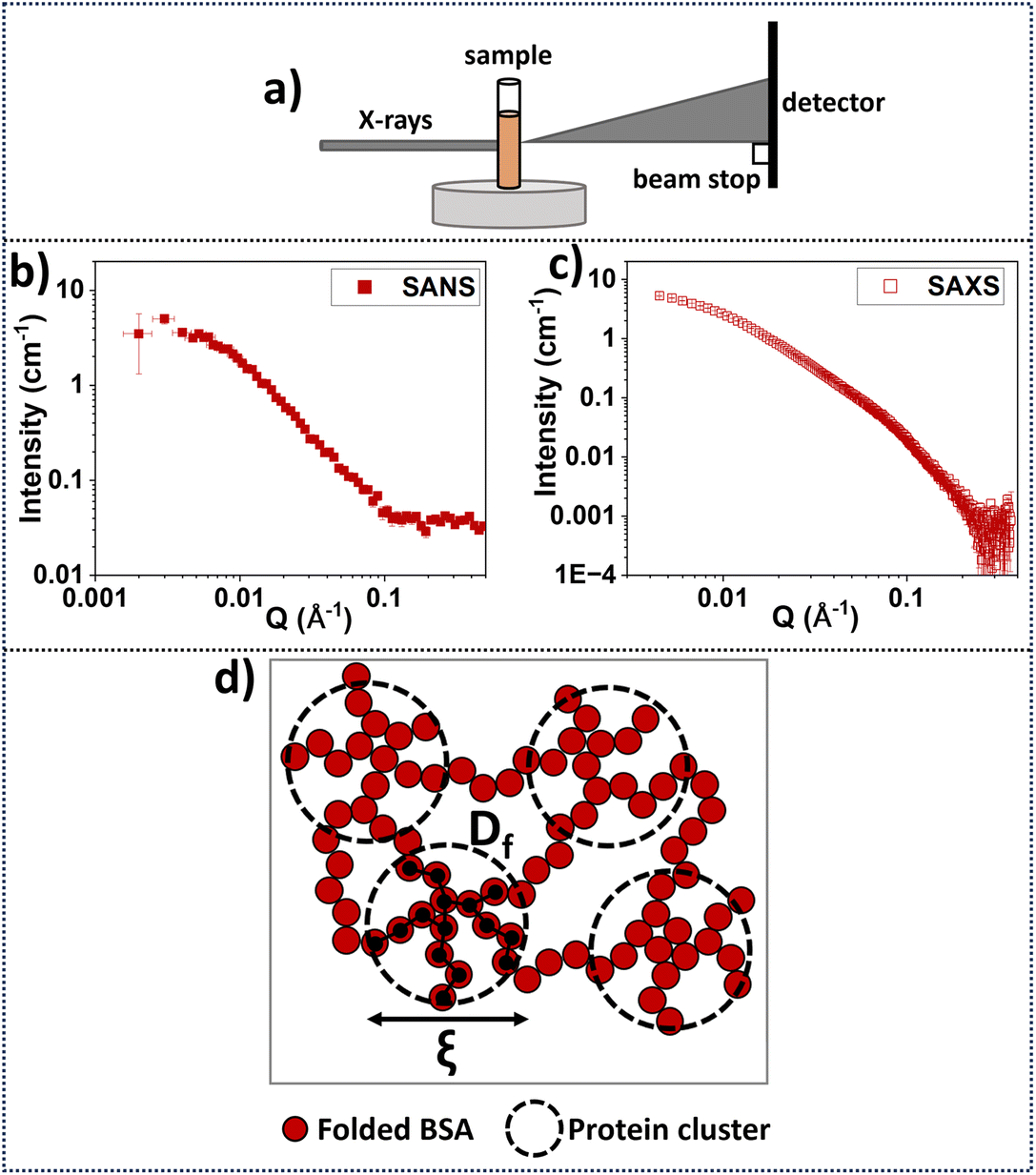 | ||
| Fig. 3 (a) Schematic of SAXS data acquisition geometry. The accessible q-range investigated in the Hughes et al. study70 was 0.0045–0.37 Å−1 and 0.002–0.5 Å−1 for SAXS and SANS, respectively. Samples were directly gelled inside sample holders.70 (b) SANS data70 from the Sans2d instrument at the ISIS neutron and Muon Source, UK, for folded BSA hydrogels (concentration: 7.4% BSA, 20 mM NaPS, 100 μM Ru(BiPy)3 in 35% D2O/65% H2O and (c) SAXS data70 from Nano-inXider instrument at the ISIS neutron and Muon Source for folded BSA hydrogels (concentration: 7.4% BSA, 20 mM NaPS, 100 μM Ru(BiPy)3 in 100% H2O).70 (d) Schematic of the predicted network structure using SANS and SAXS using model fitting of the data70 suggesting that the network consists of connected clusters made by folded protein. Correlation length ξ is indicative of the cluster size, and the fractal dimension Df can be thought of as the density of the cluster. | ||
A fractal structure factor model85 can be used to extract quantitative information from the scattering curves70 (see ESI†). From this model, two key structural parameters are obtained: the fractal dimension, Df, which is a measure of the space-filling capacity of an object and here can be thought of as the density of a cluster; and the characteristic or correlation length of the fractal-like clusters, ξ, which is related to the overall size of the clusters. Details regarding the SAS models and formulae are explained in the ESI.†
Previous SAS studies on BSA-based hydrogels have applied the fractal structure factor model and found that in the presence of DTT, the clusters become denser and larger (approximately 7 times more protein in each cluster), and the intercluster region sparser, suggesting a more heterogeneous network.70,83 It was shown that regardless of the presence of DTT, a heterogeneous hydrogel network dominated by clusters of proteins is formed. Inspired by this, cryo-SEM was used to explore BSA-based hydrogels to understand what features of the SAS structural models can be resolved by electron microscopy.
Cryo-SEM imaging using the slush nitrogen cryofixation method
Two different sample preparation routes of the same gel but of different thicknesses prior to freezing in slush nitrogen were investigated, as sample thickness can affect ice crystal growth.88 For the in situ sample preparation (Fig. 4a) a sample is gelled in the sample holder and frozen ‘in bulk’. In contrast, for the ex situ route (Fig. 4b) an already gelled sample is sectioned to be less thick than the in situ gel preparation sample, and then placed in a holder for freezing.
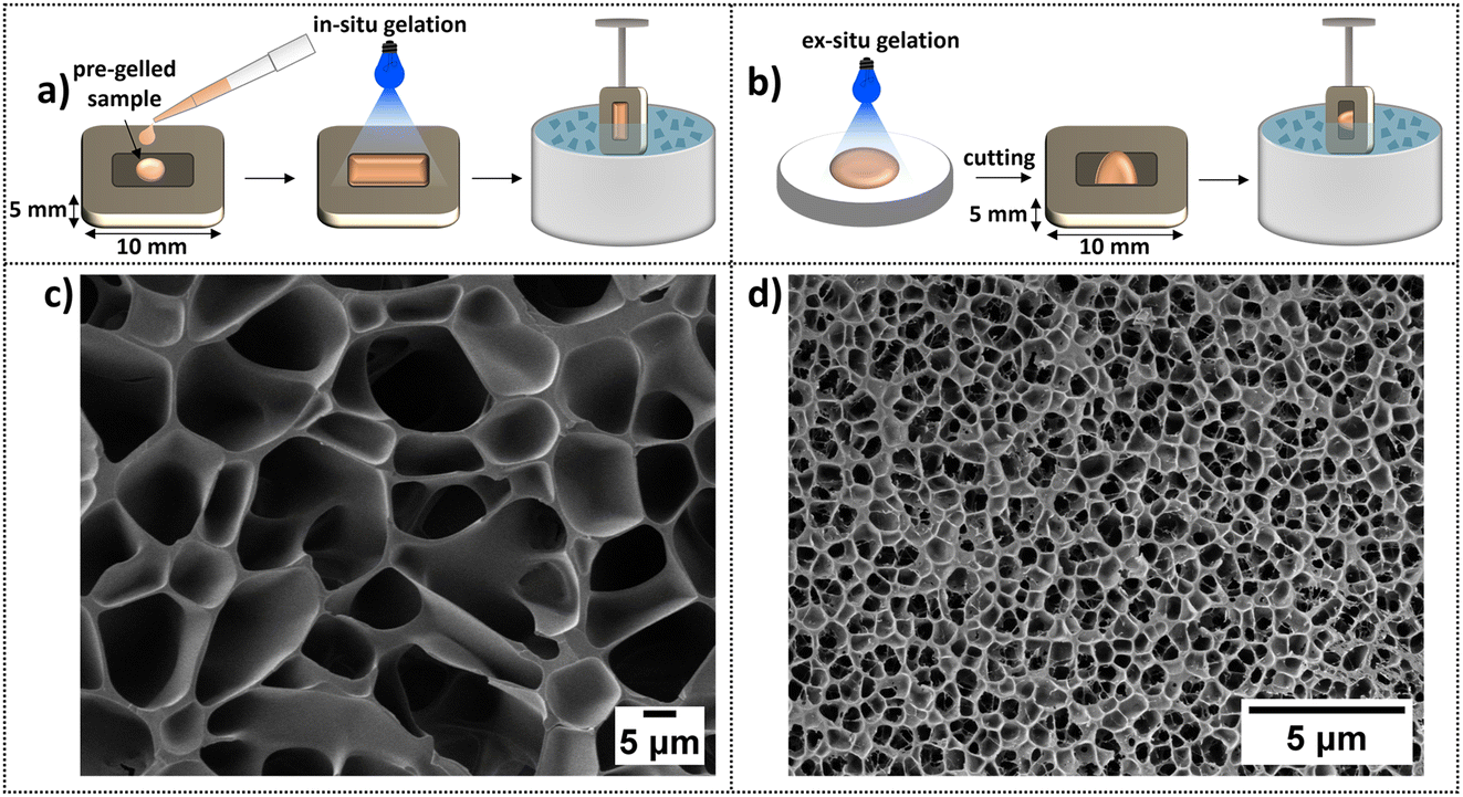 | ||
| Fig. 4 (a) Schematic of the in situ sample preparation route, which consists of directly gelling the sample in the cryo-holder before freezing in slush nitrogen. This route produces a sample thicker than 5 μm but does not require sectioning of a non-frozen gel i.e. eliminates any potential structural alteration due to knife-induced tearing or shearing. (b) Schematic of the ex situ sample preparation route, which consists of gelling the sample in a Petri dish, cutting off a thin section, which is then transferred into a cryo-holder before freezing in slush nitrogen. This route creates a thinner sample than in situ preparation but still thicker than 5 μm. (c and d) Cryo-SEM images of sublimed BSA hydrogels (7.4% BSA protein hydrogel) frozen in slush nitrogen, (c) is prepared by the (a) in situ method and (d) is prepared by the (b) ex situ method, highlighting pore formation suspected to be due to insufficient vitrification. | ||
Cryo-SEM images of the in situ and ex situ samples after sublimation are displayed in Fig. 4c and d, respectively. Both preparation routes display a honeycomb-like structure commonly reported for BSA-based systems.37–39,86,87 The average pore length for the in situ sample is 5.26 ± 0.05 μm and is ∼six times shorter for the ex situ sample, 0.72 ± 0.01 μm. Clearly, the scale of the pore sizes depends on the preparation route, and it is suggested that this is due to specimen thickness affecting ice crystal formation. i.e., the honeycomb-like structure observed is not the native network of the gels but is caused by ice crystal formation and protein displacement to the boundaries of the crystals as they nucleate and grow.
 | ||
| Fig. 5 Cryo-SEM images of a slush frozen, sublimed folded BSA hydrogel (7.4% BSA) prepared in situ prior to freezing taken from (a) the middle and (b) at the edge of the sample. (c) Decreased magnification (zoom out) image of the hydrogel highlighting the pore size difference between the edge and bulk of the hydrogel. (d) A secondary, smaller porous structure is sometimes seen within the larger pores. The location of the imaging sites within the cryo-holder is shown on the top right of each image (black dot within a white rectangle). | ||
It is also noted here that slush nitrogen freezing provides sufficient time for ice crystals to form within hydrogels regardless of the building block used. For example, Efthymiou et al. highlighted this issue when imaging heat-induced protein and polysaccharide-based hydrogels.28 Buchheim also supports this, reporting that hydrogels containing more than 80% water are expected to show structural damage due to ice crystal formation, with crystal sizes at the μm scale.90 The slush/liquid nitrogen freezing method has been used to induce ice crystal formation and create pores in hydrogels for use as scaffolds in tissue engineering applications.91 It is even clear that by modifying the cooling rate, the internal porous architecture of hydrogels can be adjusted92–94 so that if the water is sublimed, a microporous network is formed, whose size and morphology are determined by the freezing rate, temperature and sublimation conditions.95–97
Occasionally, we observed a second porous network interconnected within the larger honeycomb-like voids, as shown in Fig. 5d, which has also been reported by Aston et al. in alginate-based gels.50 This smaller network appeared as thin fibres within the larger pores. The average length of the smaller pores was 192 ± 6 nm.
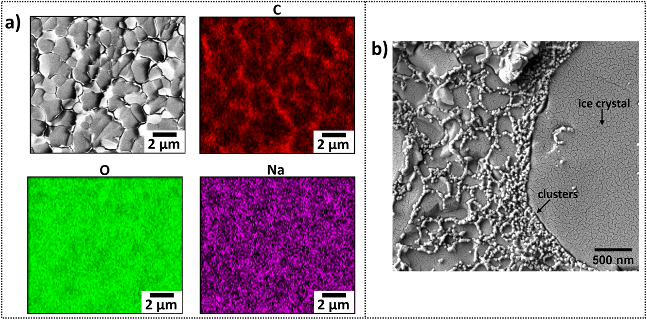 | ||
| Fig. 6 (a) Elemental mapping by EDX spectroscopy of a slush frozen, hydrated, folded BSA hydrogel (7.4% BSA) prepared ex situ prior to freezing. Assigned elements are labelled on top of each image. (b) High magnification cryo-SEM image of the same hydrogel displaying a network wall structure of interconnected clusters that have been displaced to the boundaries of the ice filled pores. | ||
A high magnification cryo-SEM image of a slush frozen, hydrated folded BSA hydrogel (7.4% BSA) prepared ex situ prior to freezing is displayed in Fig. 6b. Clusters 29.8 ± 0.4 nm connected together in a sub-network structure within the walls of the frozen gel are clearly visible. Even though these clusters are compressed together at the pore walls, the undeformed network structure is similar to that predicted by modelling of SAS data (Fig. 3c).70Fig. 6 indicates what can be achieved by elemental mapping and high-resolution imaging with the appropriate cryo-SEM sample preparation.
Cryo-SEM imaging using the high-pressure freezing (HPF) cryofixation method
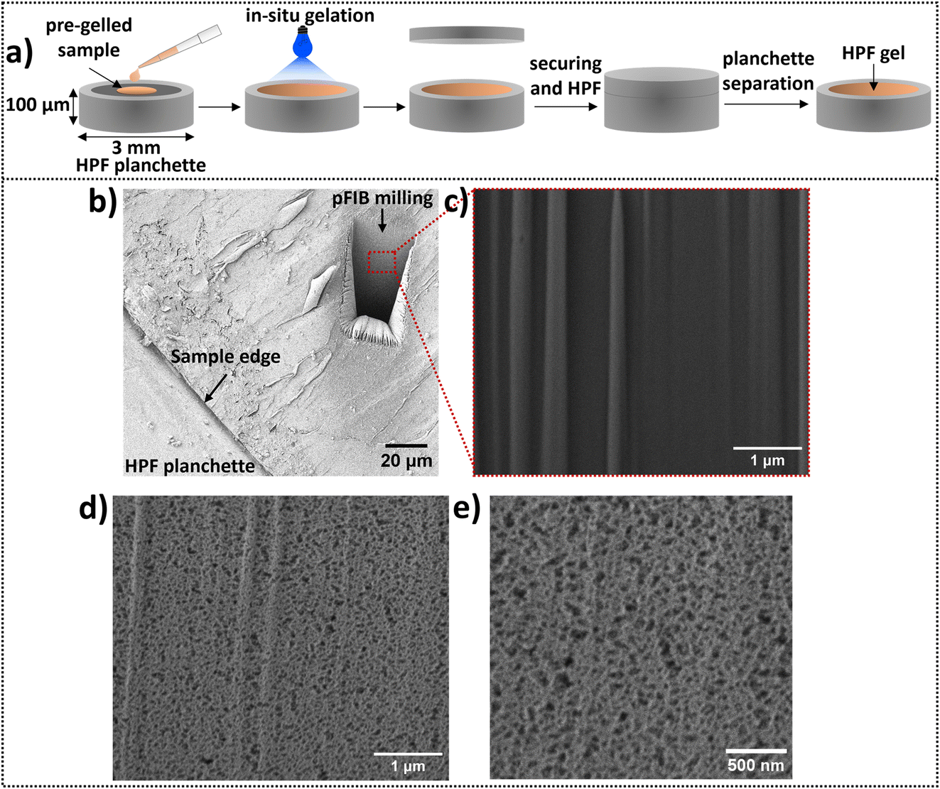 | ||
| Fig. 7 The methodology used to acquire an image of an HPF, pFIB milled and sublimed folded BSA hydrogel (7.4% BSA) prepared in situ prior to HPF. (a) Schematic representation of the in situ sample preparation. The sample is directly gelled into a 100 μm deep planchette, leaving no void space. Then, a second flat planchette is placed on top, securing the sample prior to HPF. After HPF, the planchettes are separated, exposing the frozen, hydrated gel. (b–e) Cryo-SEM images of the HPF BSA hydrogel after: (b) pFIB milling was used to expose the inner structure of the hydrogels; (c and d) Images obtained from the front side of the milled area (c) before and (d) after sublimation exposing the pores; (e) increased magnification of the milled area after sublimation. | ||
A high magnification cryo-SEM image of an HPF, pFIB milled and sublimed, folded BSA (7.4% BSA) hydrogel is shown in Fig. 7e. The structure difference between the hydrogels frozen by HPF and in slush nitrogen is striking (Fig. 4vs.Fig. 7). The pores of the HPF samples appear rounded, are 58.3 ± 0.2 nm across and are two orders of magnitude smaller than the pores in the bulk regions of the slush nitrogen frozen hydrogels (5.26 ± 0.05 μm).
The pore sizes and heterogeneous network structure measured by the HPF sample preparation are similar but smaller to those within 2–5 μm of the edge of the slush frozen gel (and are similar to the secondary networks seen within some pores of the bulk slush frozen gel; Fig. 5c and d). Aston et al. observed a similar behaviour in alginate-based hydrogels.50
 | ||
| Fig. 8 (a) Schematic of a route for obtaining representative images of cryo-fixed hydrogels. The steps consist of in situ gelation ensuring no mechanical structural alteration, HPF assuring vitreous freezing, pFIB milling to expose the inner structure and sublimation to expose the pores and structural features of the hydrogels. (b) Processed high magnification images of a folded BSA hydrogel (7.4% BSA) prepared following the steps in panel a, highlighting image analysis possibilities. (b, i) High contrast image for cluster (orange) and intercluster distance (green) measurements. (b, ii) Threshold image for pore size (black voids) analysis. | ||
Low current, low kV secondary electron imaging of the cryo-fixed hydrogels is required to reveal pores within a network composed of regions of high secondary electron emission connected by narrower, lower emission regions. Fig. 8b(i) is a high contrast version of the image in Fig. 7e and in this we can assign the regions of high secondary electron emission as clusters (highlighted as orange spheres) and the lengths across the lower emission regions as intercluster distances (highlighted as green lines). The average cluster diameter is 30.1 ± 0.6 nm and the intercluster distance 20 ± 1 nm. From SANS data, the extracted correlation length ξ for BSA hydrogels was 12.3 nm, which is indicative of the average cluster size across the whole network.70 Interestingly, the value of ξ is the same order of magnitude as the individual protein cluster diameter directly measured in the cryo-SEM images of the hydrogel network. While models are required to obtain the network structure from SANS data, cryo-SEM is a powerful method to directly visualise the heterogeneous network and complement SAS derived models to gain valuable information regarding the pore structure of folded-based hydrogels.
Network pore sizes can be obtained by thresholding the image of Fig. 7e such that pores have black contrast and any other structure has white contrast (using ImageJ software and shown in Fig. 8b(ii)). The average pore size of the folded BSA gel is 58.3 ± 0.2 nm. We confirm that low electron doses are required to maintain the network integrity and not alter the pore size distributions by demonstrating an increase in measured pore size and pore size distribution with prolonged irradiation of the sample (Fig. S1†).
BSA is an ideal model protein due to its mechanical ‘nanostaples’ preventing BSA from unfolding. The addition of DTT allows BSA to unfold during gelation, and this has an impact on the structure and mechanics of the hydrogel network, as shown schematically in Fig. 9a.70 From previous SANS studies of a 7.4% BSA hydrogel,70 it was found that the measured fractal dimension Df of a cross-linked cluster is larger in BSA hydrogels formed in the presence of DTT (Df = 2.66 in the presence and 2.17 in the absence of DTT). The correlation length, which is indicative of the cluster size, also increases in the presence of DTT (ξ = 123 Å in the absence of DTT and 130 Å in the presence of DTT). More recently, SAXS studies of a 7.4% BSA hydrogel used model-independent Guinier–Porod fits to SAXS curves to extract the Porod exponent and the radius of gyration of the largest scattering object.82,100 The data showed Rg = 140 Å and Df = 2.5 in the absence of DTT82 and Rg = 200 Å and Df = 2.8 in the presence of DTT.100 Application of the fractal structure factor model to the SAXS data yielded a ξ = 116 Å and Df = 2.48 in the absence of DTT and ξ = 166 Å and Df = 2.75 in the presence of DTT.100 Whilst the exact numbers show differences, in all cases, BSA hydrogels in the presence of DTT show an increase in Rg, ξ and Df. Taken together, this suggests that hydrogels made from force-labile BSA (nanostaples removed) form denser fractal-like clusters of larger size compared to the clusters present in hydrogels made from mechanically robust BSA (nanostaples present). Cryo-SEM by HPF, FIB milling and sublimation has the potential to directly visualise these structural changes upon protein unfolding while also observing the induced changes to pore sizes within the protein hydrogel architectures.
 | ||
| Fig. 9 Controlling protein unfolding in situ influences gel mechanics and structure. (a) From left to right: Schematic of the 3D structure of BSA highlighting the disulphide bonds (nanostaples) in yellow, which hold BSA in a folded state. The nanostaples preserve the mechanical robustness of the protein. Removal of the nanostaples makes the protein force labile, leading to unfolding during gelation and ultimately to network alteration and a loss of mechanical rigidity. SAS schematics of the corresponding structures highlight structural changes in the network.70 (b and c) High contrast cryo-SEM images of HPF, pFIB milled and sublimed prepared in situ prior to freezing (b) folded BSA (7.4% BSA) (mechanically robust protein) and (c) unfolded BSA:DTT (7.4% BSA) (force labile protein) gels, with highlighted image analysis. Orange spheres represent the clusters, and green lines the intercluster distances. (d) Average pore length of gels made by mechanically robust BSA (light red) and force labile BSA (dark red), as extracted by cryo-SEM images. (e) Cluster diameter measurements of gels made by mechanically robust BSA (light red) and force labile BSA (dark red) as extracted by cryo-SEM. (f) Intercluster distance measurements of gels made by mechanically robust BSA (light red) and force labile BSA (dark red) as extracted by cryo-SEM. Error bars display the standard error of the mean. | ||
High magnification and contrast adjusted images of the structure of mechanically robust BSA (nanostaples present) and force-labile BSA (nanostaples removed) hydrogels prepared by our methodology (Fig. 8a) are displayed in Fig. 9b and c, respectively. For both systems, a heterogeneous network is observed with porosity directly visible within a network dominated by clusters and intercluster connections or ‘walls’. The average cluster diameters, highlighted as orange spheres in Fig. 9b and c were measured to be 30.1 ± 0.6 nm and 44.2 ± 0.6 nm in the absence and presence of DTT, respectively. The cluster diameters extracted from cryo-SEM (Fig. 9e) follow the same trend as those extracted from the SANS data with an increase in cluster diameter for networks made from force labile BSA protein. Intercluster distances, highlighted as green lines in the cryo-SEM images of Fig. 9b and c, are 20 ± 1 nm and 27 ± 2 nm for the mechanically robust and force labile BSA systems, respectively (Fig. 9f).
Whilst it is known that making BSA force labile by protein unfolding during gelation creates a gel network with bigger, more well-spaced protein clusters, we can for the first time, use cryo-SEM to image directly the porosity changes within this structure. The average pore length (Fig. 9d) is measured to be 58.3 ± 0.2 nm in the absence of DTT, and 67.0 ± 1.4 nm in the presence of DTT, i.e. we can confirm an increase in pore sizes with protein unfolding and visualise the expected increase in heterogeneity of the DTT exposed gels.
Overall, we show that appropriate sample preparation for cryo-SEM by HPF of folded protein hydrogels can be used to gain information about the morphology and pore sizes of protein-based systems and image the impact of unfolding in the network through image analysis. We evaluated our cryo-SEM findings by comparing the results with previous SAS studies.2,70,73,81–83 The importance of such an integrated approach to assess the structure and characteristics (parameters) of a network and even to validate image analysis tools has been highlighted by a number of recent studies.12,101,102 Often, different parameters can be extracted from different techniques, rendering direct comparison of results challenging. From SAS data, we can extract a radius of gyration Rg, correlation length ξ, and fractal dimension Df which are indicative of the lengthscale of the fractal clusters within a network. To directly compare with the cryo-SEM analysis, it will be necessary to measure an ensemble of individual cluster diameters from a number of images. Likewise, it would be powerful if the measure of pore sizes obtained by cryo-SEM could be compared to the porosity in the protein hydrogels studied using SAS. This highlights the importance of retrieving equivalent parameters and understanding how extracted parameters of different techniques can correlate to each other. As this comparison develops, the combination of SAS and cryo-SEM data for the study of protein hydrogels provides an opportunity to understand both the hierarchical structure of the protein network and the resulting pore sizes of the hydrogel, both of which are critical parameters that describe the heterogeneity of the gel as a whole and give rise to much of its function.
An additional critical factor for extracting key parameters of the system, such as cluster diameter and intercluster distances, is to develop automated approaches that could measure these parameters from the images obtained, reducing potential bias and time-consuming methods such as manual measurements. The importance of developing image analysis tools that could be applied to these systems has been underlined by a comprehensive overview and comparison of available automated tools for quantifying characteristics of fibrous networks, such as fibre diameter and length.103 Current state-of-the-art image analysis approaches of other microscopy techniques could provide insights for developing similar cryo-SEM analysis tools. In confocal microscopy, studies have developed methods to extract the pore size distribution of polymeric networks in 2-D images by placing circles (or bubbles) of the maximum diameter that could fit the pores until full coverage is achieved.104–106 At the same time, in super-resolution microscopy, studies have started to implement new computational methods for data quantification and interpretation due to rapid imaging advances in the field.102 For stimulated emission depletion (STED) microscopy, image autocorrelation analysis was employed to quantify the spatial distribution of fluorophores.107 Super-resolution diffusion maps have been used to estimate pore sizes of polymeric-based hydrogels.108
Ultimately, imaging network pores by cryo-SEM opens the possibility of directly accessing information on network architectures and the role of perturbations such as protein unfolding on those structures. For example, a recent study has demonstrated the potential of active particles in ‘kneading’ three-dimensional hydrogels into porous structures.109 Such studies offer the potential to create a diversity of heterogeneous, percolated porous networks which would be exploited for new functional and response biomaterials. The application of cryo-SEM to appropriately prepared samples could provide powerful insights into active particle-induced porosity changes in such materials.109 It is expected that hydrogels will have controlled morphologies across individual building blocks to bulk lengthscales, enabling the creation of complex systems, though with significant advancements still required.110
Conclusions
In this study, we have developed a reproducible protocol to prepare and image protein-based hydrogels, minimising and overcoming artefacts caused by cryo-SEM. This protocol consists of in situ sample preparation prior to freezing to avoid alterations due to mechanical stressing, high pressure freezing to ensure sufficient vitrification, plasma focussed ion beam milling to avoid network compression and sublimation to expose the native structure of the hydrogels. The protocol measures structural differences in the hydrogel networks formed by folded and unfolded protein-based hydrogels. In order to accurately measure differences in the protein network structure, the first steps for image analysis were conducted such that cryo-SEM reveals a heterogeneous network of a folded protein hydrogel to have nanoscale porosity (∼60 nm pores) composed of regions of high protein density (∼30 nm diameter) connected by thinner, lower density regions (∼20 nm in length). Cryo-SEM also shows that protein unfolding induces an increase in network heterogeneity, including an increase of ∼10 nm in average pore sizes. Our findings on sample preparation challenges and solutions for imaging protein-based hydrogels using cryo-SEM ultimately present the opportunity to understand the structure-to-function relationship of many hydrogel systems.Data availability
The data supporting the findings of the paper are available at: https://doi.org/10.5518/1633.Conflicts of interest
There are no conflicts to declare.Acknowledgements
The project is supported by the Engineering and Physical Sciences Research Council (EPSRC) Centre for Doctoral Training (CDT) in Molecules to Product grant Ref. EP/S022479/1. The project was supported by a grant from the European Research Council (ERC) (UKRI EP/X023524/1) to L. Dougan. The electron microscope used in this work was funded by the Engineering and Physical Sciences Research Council (EPSRC), UK under grant EP/V028855/1. We kindly acknowledge the Leeds Electron Microscopy and Spectroscopy (LEMAS) Centre and the Astbury Centre for Structural Molecular Biology of the University of Leeds for facility access and support. Lastly, all members of the Dougan group are gratefully thanked for their feedback and discussions.References
- R. Mout, R. C. Bretherton, J. Decarreau, S. Lee, N. Gregorio and N. I. Edman, et al., De novo design of modular protein hydrogels with programmable intra- and extracellular viscoelasticity, Proc. Natl. Acad. Sci. U. S. A., 2024, 121(6), e2309457121, DOI:10.1073/pnas.2309457121.
- A. Aufderhorst-Roberts, M. D. G. Hughes, A. Hare, D. A. Head, N. Kapur and D. J. Brockwell, et al., Reaction Rate Governs the Viscoelasticity and Nanostructure of Folded Protein Hydrogels, Biomacromolecules, 2020, 21(10), 4253–4260, DOI:10.1021/acs.biomac.0c01044.
- H. Le Roy, J. Song, D. Lundberg, A. V. Zhukhovitskiy, J. A. Johnson and G. H. McKinley, et al., Valence can control the nonexponential viscoelastic relaxation of multivalent reversible gels, Sci. Adv., 2024, 10(20), eadl5056, DOI:10.1126/sciadv.adl5056.
- D. N. Tavakol, J. Tratwal, F. Bonini, M. Genta, V. Campos and P. Burch, et al., Injectable, scalable 3D tissue-engineered model of marrow hematopoiesis, Biomaterials, 2020, 232, 119665, DOI:10.1016/j.biomaterials.2019.119665.
- Y. Huang, V. Fitzpatrick, N. Zheng, R. Cheng, H. Huang and C. Ghezzi, et al., Self-Folding 3D Silk Biomaterial Rolls to Facilitate Axon and Bone Regeneration, Adv. Healthcare Mater., 2020, 9(18), 2000530, DOI:10.1002/adhm.202000530.
- P. Yang, H. Song, Y. Qin, P. Huang, C. Zhang and D. Kong, et al., Engineering Dendritic-Cell-Based Vaccines and PD-1 Blockade in Self-Assembled Peptide Nanofibrous Hydrogel to Amplify Antitumor T-Cell Immunity, Nano Lett., 2018, 18(7), 4377–4385, DOI:10.1021/acs.nanolett.8b01406.
- W. Sun, T. Duan, Y. Cao and H. Li, An Injectable Self-Healing Protein Hydrogel with Multiple Dissipation Modes and Tunable Dynamic Response, Biomacromolecules, 2019, 20(11), 4199–4207, DOI:10.1021/acs.biomac.9b01114.
- C. Huerta-López and J. Alegre-Cebollada, Protein Hydrogels: The Swiss Army Knife for Enhanced Mechanical and Bioactive Properties of Biomaterials, Nanomaterials, 2021, 11(7), 1656, DOI:10.3390/nano11071656.
- K. Z. Lee, J. Jeon, B. Jiang, S. V. Subramani, J. Li and F. Zhang, Protein-Based Hydrogels and Their Biomedical Applications, Molecules, 2023, 28(13), 4988, DOI:10.3390/molecules28134988.
- E. R. Draper and D. J. Adams, How should multicomponent supramolecular gels be characterised?, Chem. Soc. Rev., 2018, 47(10), 3395–3405, 10.1039/C7CS00804J.
- G. Yu, X. Yan, C. Han and F. Huang, Characterization of supramolecular gels, Chem. Soc. Rev., 2013, 42(16), 6697–6722, 10.1039/C3CS60080G.
- C. R. M. MacDonald and E. R. Draper, Applications of microscopy and small angle scattering techniques for the characterisation of supramolecular gels, Beilstein J. Org. Chem., 2024, 20, 2608–2634, DOI:10.3762/bjoc.20.220.
- V. S. Raghuwanshi and G. Garnier, Characterisation of hydrogels: Linking the nano to the microscale, Adv. Colloid Interface Sci., 2019, 274, 102044, DOI:10.1016/j.cis.2019.102044.
- D. McDowall, D. J. Adams and A. M. Seddon, Using small angle scattering to understand low molecular weight gels, Soft Matter, 2022, 18(8), 1577–1590, 10.1039/D1SM01707A.
- R. Kubota, W. Tanaka and I. Hamachi, Microscopic Imaging Techniques for Molecular Assemblies: Electron, Atomic Force, and Confocal Microscopies, Chem. Rev., 2021, 121(22), 14281–14347, DOI:10.1021/acs.chemrev.0c01334.
- I. Jayawardena, P. Turunen, B. C. Garms, A. Rowan, S. Corrie and L. Grøndahl, Evaluation of techniques used for visualisation of hydrogel morphology and determination of pore size distributions, Mater. Adv., 2023, 4(2), 669–682, 10.1039/D2MA00932C.
- C. Marmorat, A. Arinstein, N. Koifman, Y. Talmon, E. Zussman and M. Rafailovich, Cryo-Imaging of Hydrogels Supermolecular Structure, Sci. Rep., 2016, 6(1), 25495, DOI:10.1038/srep25495.
- L. Wang, X. Shi and J. Wang, A temperature-responsive supramolecular hydrogel: preparation, gel–gel transition and molecular aggregation, Soft Matter, 2018, 14(16), 3090–3095, 10.1039/C8SM00220G.
- J. Boekhoven, J. M. Poolman, C. Maity, F. Li, L. van der Mee and C. B. Minkenberg, et al., Catalytic control over supramolecular gel formation, Nat. Chem., 2013, 5(5), 433–437, DOI:10.1038/nchem.1617.
- Q. Liu, Y. Wang, W. Li and L. Wu, Structural Characterization and Chemical Response of a Ag-Coordinated Supramolecular Gel, Langmuir, 2007, 23(15), 8217–8223, DOI:10.1021/la700364t.
- S. Kiyonaka, S. L. Zhou and I. Hamachi, pH-Responsive Phase Transition of Supramolecular Hydrogel Consisting of Glycosylated Amino Acetate and Carboxylic Acid Derivative, Supramol. Chem., 2003, 15(7–8), 521–528, DOI:10.1080/10610270310001605115.
- F. D. Martinez-Garcia, T. Fischer, A. Hayn, C. T. Mierke, J. K. Burgess and M. C. Harmsen, A Beginner's Guide to the Characterization of Hydrogel Microarchitecture for Cellular Applications, Gels, 2022, 8(9), 535, DOI:10.3390/gels8090535.
- R. F. Egerton and Y. Zhu, Spatial resolution in secondary-electron microscopy, Microscopy, 2023, 72(2), 66–77, DOI:10.1093/jmicro/dfac022.
- D. F. Bray, J. Bagu and P. Koegler, Comparison of hexamethyldisilazane (HMDS), Peldri II, and critical-point drying methods for scanning electron microscopy of biological specimens, Microsc. Res. Tech., 1993, 26(6), 489–495, DOI:10.1002/jemt.1070260603.
- S. M. Paterson, Y. S. Casadio, D. H. Brown, J. A. Shaw, T. V. Chirila and M. V. Baker, Laser scanning confocal microscopy versus scanning electron microscopy for characterization of polymer morphology: Sample preparation drastically distorts morphologies of poly(2-hydroxyethyl methacrylate)-based hydrogels, J. Appl. Polym. Sci., 2013, 127(6), 4296–4304, DOI:10.1002/app.38034.
- D. J. Merryweather, N. Weston, J. Roe, C. Parmenter, M. P. Lewis and P. Roach, Exploring the microstructure of hydrated collagen hydrogels under scanning electron microscopy, J. Microsc., 2023, 290(1), 40–52, DOI:10.1111/jmi.13174.
- M. Koch and M. K. Włodarczyk-Biegun, Faithful scanning electron microscopic (SEM) visualization of 3D printed alginate-based scaffolds, Bioprinting, 2020, 20, e00098, DOI:10.1016/j.bprint.2020.e00098.
- C. Efthymiou, M. A. K. Williams and K. M. McGrath, Revealing the structure of high-water content biopolymer networks: Diminishing freezing artefacts in cryo-SEM images, Food Hydrocolloids, 2017, 73, 203–212, DOI:10.1016/j.foodhyd.2017.06.040.
- R. A. Fleck, Low-Temperature Electron Microscopy: Techniques and Protocols, in Cryopreservation and Freeze-Drying Protocols, ed. W. F. Wolkers and H. Oldenhof, Springer New York, New York, NY, 2015, pp. 243–274, DOI:10.1007/978-1-4939-2193-5_9.
- D. Serp, M. Mueller, U. von Stockar and I. W. Marison, Low-temperature electron microscopy for the study of polysaccharide ultrastructures in hydrogels. I. Theoretical and technical considerations, Biotechnol. Bioeng., 2002, 79(3), 243–252, DOI:10.1002/bit.10286.
- L. Bachmann and E. Mayer, Physics of Water and Ice: Implications for Cryofixation, in Cryotechniques in Biological Electron Microscopy, ed. R. A. Steinbrecht and K. Zierold, Springer Berlin Heidelberg, Berlin, Heidelberg, 1987, pp. 3–34, DOI:10.1007/978-3-642-72815-0_1.
- J. Dubochet, The Physics of Rapid Cooling and Its Implications for Cryoimmobilization of Cells, in Cellular Electron Microscopy, Academic Press, Methods in Cell Biology, 2007, vol. 79, pp. 7–21, DOI:10.1016/S0091-679X(06)79001-X.
- I. Hurbain and M. Sachse, The future is cold: cryo-preparationmethods for transmission electron microscopy of cells, Biol. Cell, 2011, 103(9), 405–420, DOI:10.1042/BC20110015.
- J. Dubochet and H. Stahlberg, Electron Cryomicroscopy, in eLS, John Wiley & Sons, Ltd, 2001, DOI:10.1038/npg.els.0002999.
- M. Shimoni, On optimizing high-pressure freezing: from heat transfer theory to a new microbiopsy device, J. Microsc., 1998, 192(3), 236–247, DOI:10.1046/j.1365-2818.1998.00389.x.
- G. Weissenberger, R. J. M. Henderikx and P. J. Peters, Understanding the invisible hands of sample preparation for cryo-EM, Nat. Methods, 2021, 18(5), 463–471, DOI:10.1038/s41592-021-01130-6.
- L. R. Khoury and I. Popa, Chemical unfolding of protein domains induces shape change in programmed protein hydrogels, Nat. Commun., 2019, 10(1), 5439, DOI:10.1038/s41467-019-13312-0.
- D. Lantigua, M. A. Nguyen, X. Wu, S. Suvarnapathaki, S. Kwon and W. Gavin, et al., Synthesis and characterization of photocrosslinkable albumin-based hydrogels for biomedical applications, Soft Matter, 2020, 16(40), 9242–9252, 10.1039/D0SM00977F.
- X. Ma, X. Sun, D. Hargrove, J. Chen, D. Song and Q. Dong, et al., A Biocompatible and Biodegradable Protein Hydrogel with Green and Red Autofluorescence: Preparation, Characterization and In Vivo Biodegradation Tracking and Modeling, Sci. Rep., 2016, 6(1), 19370, DOI:10.1038/srep19370.
- J. Fang, A. Mehlich, N. Koga, J. Huang, R. Koga and X. Gao, et al., Forced protein unfolding leads to highly elastic and tough protein hydrogels, Nat. Commun., 2013, 4(1), 2974, DOI:10.1038/ncomms3974.
- M. N. Lopez, M. Owens, S. Schmidt, A. F. Silva and M. Bradley, Poly-Epsilon-Lysine Hydrogels with Dynamic Crosslinking Facilitates Cell Proliferation, Materials, 2020, 13(17), 3851, DOI:10.3390/ma13173851.
- C. Kyomugasho, S. Christiaens, D. Van de Walle, A. M. Van Loey, K. Dewettinck and M. E. Hendrickx, Evaluation of cation-facilitated pectin-gel properties: Cryo-SEM visualisation and rheological properties, Food Hydrocolloids, 2016, 61, 172–182, DOI:10.1016/j.foodhyd.2016.05.018.
- J. Y. Kim, J. Y. Song, E. J. Lee and S. K. Park, Rheological properties and microstructures of Carbopol gel network system, Colloid Polym. Sci., 2003, 281(7), 614–623, DOI:10.1007/s00396-002-0808-7.
- X. Yu, J. Cai, M. Xu, Q. Li, Y. Yang and Z. Wan, et al., A natural food-grade supramolecular self-assembly system for creation of hierarchically structured hydrogels, Nanoscale, 2024, 16(30), 14261–14268, 10.1039/D4NR01410C.
- G. E. Sosinsky, J. Crum, Y. Z. Jones, J. Lanman, B. Smarr and M. Terada, et al., The combination of chemical fixation procedures with high pressure freezing and freeze substitution preserves highly labile tissue ultrastructure for electron tomography applications, J. Struct. Biol., 2008, 161(3), 359–371, DOI:10.1016/j.jsb.2007.09.002.
- R. Dahl and L. A. Staehelin, High-pressure freezing for the preservation of biological structure: Theory and practice, J. Electron Microsc. Tech., 1989, 13(3), 165–174, DOI:10.1002/jemt.1060130305.
- D. Studer, B. M. Humbel and M. Chiquet, Electron microscopy of high pressure frozen samples: bridging the gap between cellular ultrastructure and atomic resolution, Histochem. Cell Biol., 2008, 130(5), 877–889, DOI:10.1007/s00418-008-0500-1.
- G. E. Sosinsky, J. Crum, Y. Z. Jones, J. Lanman, B. Smarr and M. Terada, et al., The combination of chemical fixation procedures with high pressure freezing and freeze substitution preserves highly labile tissue ultrastructure for electron tomography applications, J. Struct. Biol., 2008, 161(3), 359–371, DOI:10.1016/j.jsb.2007.09.002.
- N. Sartori, K. Richter and J. Dubochet, Vitrificationdepth can be increased more than 10-fold by high-pressure freezing, J. Microsc., 1993, 172(1), 55–61, DOI:10.1111/j.1365-2818.1993.tb03393.x.
- R. Aston, K. Sewell, T. Klein, G. Lawrie and L. Grøndahl, Evaluation of the impact of freezing preparation techniques on the characterisation of alginate hydrogels by cryo-SEM, Eur. Polym. J., 2016, 82, 1–15, DOI:10.1016/j.eurpolymj.2016.06.025.
- G. Navarra, C. Peres, M. Contardi, P. Picone, P. L. San Biagio and M. Di Carlo, et al., Heat- and pH-induced BSA conformational changes, hydrogel formation and application as 3D cell scaffold, Arch. Biochem. Biophys., 2016, 606, 134–142, DOI:10.1016/j.abb.2016.07.020.
- S. Khanna, A. K. Singh, S. P. Behera and S. Gupta, Thermoresponsive BSA hydrogels with phase tunability, Mater. Sci. Eng., C, 2021, 119, 111590, DOI:10.1016/j.msec.2020.111590.
- T. Nicolai and C. Chassenieux, Heat-induced gelation of plant globulins, Curr. Opin. Food Sci., 2019, 27, 18–22, DOI:10.1016/j.cofs.2019.04.005.
- W. Ren, W. Xia, D. Z. Gunes and L. Ahrné, Heat-induced gels from pea protein soluble colloidal aggregates: Effect of calcium addition or pH adjustment on gelation behavior and rheological properties, Food Hydrocolloids, 2024, 147, 109417, DOI:10.1016/j.foodhyd.2023.109417.
- S. Lv, D. M. Dudek, Y. Cao, M. M. Balamurali, J. Gosline and H. Li, Designed biomaterials to mimic the mechanical properties of muscles, Nature, 2010, 465(7294), 69–73, DOI:10.1038/nature09024.
- Y. Li, B. Xue and Y. Cao, 100th Anniversary of Macromolecular Science Viewpoint: Synthetic Protein Hydrogels, ACS Macro Lett., 2020, 9(4), 512–524, DOI:10.1021/acsmacrolett.0c00109.
- H. Li, N. Kong, B. Laver and J. Liu, Hydrogels Constructed from Engineered Proteins, Small, 2016, 12(8), 973–987, DOI:10.1002/smll.201502429.
- K. Wei, B. Senturk, M. T. Matter, X. Wu, I. K. Herrmann and M. Rottmar, et al., Mussel-Inspired Injectable Hydrogel Adhesive Formed under Mild Conditions Features Near-Native Tissue Properties, ACS Appl. Mater. Interfaces, 2019, 11(51), 47707–47719, DOI:10.1021/acsami.9b16465.
- N. Kong, L. Fu, Q. Peng and H. Li, Metal Chelation Dynamically Regulates the Mechanical Properties of Engineered Protein Hydrogels, ACS Biomater. Sci. Eng., 2017, 3(5), 742–749, DOI:10.1021/acsbiomaterials.6b00374.
- M. L. Zhou, Z. G. Qian, L. Chen, D. L. Kaplan and X. X. Xia, Rationally Designed Redox-Sensitive Protein Hydrogels with Tunable Mechanical Properties, Biomacromolecules, 2016, 17(11), 3508–3515, DOI:10.1021/acs.biomac.6b00973.
- T. Duan and H. Li, In Situ Phase Transition of Elastin-Like Polypeptide Chains Regulates Thermoresponsive Properties of Elastomeric Protein-Based Hydrogels, Biomacromolecules, 2020, 21(6), 2258–2267, DOI:10.1021/acs.biomac.0c00206.
- L. Fu, A. Haage, N. Kong, G. Tanentzapf and H. Li, Dynamic protein hydrogels with reversibly tunable stiffness regulate human lung fibroblast spreading reversibly, Chem. Commun., 2019, 55(36), 5235–5238, 10.1039/C9CC01276A.
- N. Kong, Q. Peng and H. Li, Rationally Designed Dynamic Protein Hydrogels with Reversibly Tunable Mechanical Properties, Adv. Funct. Mater., 2014, 24(46), 7310–7317, DOI:10.1002/adfm.201402205.
- L. R. Khoury, M. Slawinski, D. R. Collison and I. Popa, Cation-induced shape programming and morphing in protein-based hydrogels, Sci. Adv., 2020, 6(18), eaba6112, DOI:10.1126/sciadv.aba6112.
- J. Wu, P. Li, C. Dong, H. Jiang, B. Xue and X. Gao, et al., Rationally designed synthetic protein hydrogels with predictable mechanical properties, Nat. Commun., 2018, 9(1), 620, DOI:10.1038/s41467-018-02917-6.
- D. S. Knoff, H. Szczublewski, D. Altamirano, K. A. Fajardo Cortes and M. Kim, Cytoskeleton-Inspired Artificial Protein Design to Enhance Polymer Network Elasticity, Macromolecules, 2020, 53(9), 3464–3471, DOI:10.1021/acs.macromol.0c00514.
- D. Dranseike, Y. Ota, T. G. W. Edwardson, E. A. Guzzi, M. Hori and Z. R. Nakic, et al., Designed modular protein hydrogels for biofabrication, Acta Biomater., 2024, 177, 107–117, DOI:10.1016/j.actbio.2024.02.019.
- M. D. G. Hughes, S. Cussons, B. S. Hanson, K. R. Cook, T. Feller and N. Mahmoudi, et al., Building block aspect ratio controls assembly, architecture, and mechanics of synthetic and natural protein networks, Nat. Commun., 2023, 14(1), 5593, DOI:10.1038/s41467-023-40921-7.
- M. A. da Silva, S. Lenton, M. Hughes, D. J. Brockwell and L. Dougan, Assessing the Potential of Folded Globular Polyproteins As Hydrogel Building Blocks, Biomacromolecules, 2017, 18(2), 636–646, DOI:10.1021/acs.biomac.6b01877.
- M. D. G. Hughes, B. S. Hanson, S. Cussons, N. Mahmoudi, D. J. Brockwell and L. Dougan, Control of Nanoscale In Situ Protein Unfolding Defines Network Architecture and Mechanics of Protein Hydrogels, ACS Nano, 2021, 15(7), 11296–11308, DOI:10.1021/acsnano.1c00353.
- N. Sadaba, E. Sanchez-Rexach, C. Waltmann, S. L. Hilburg, L. D. Pozzo and M. Olvera de la Cruz, et al., Strain learning in protein-based mechanical metamaterials, Proc. Natl. Acad. Sci. U. S. A., 2024, 121(45), e2407929121, DOI:10.1073/pnas.2407929121.
- L. Fu, L. Li, Q. Bian, B. Xue, J. Jin and J. Li, et al., Cartilage-like protein hydrogels engineered via entanglement, Nature, 2023, 618(7966), 740–747, DOI:10.1038/s41586-023-06037-0.
- M. D. G. Hughes, S. Cussons, N. Mahmoudi, D. J. Brockwell and L. Dougan, Tuning Protein Hydrogel Mechanics through Modulation of Nanoscale Unfolding and Entanglement in Postgelation Relaxation, ACS Nano, 2022, 16(7), 10667–10678, DOI:10.1021/acsnano.2c02369.
- F. Kong, N. Mehwish and B. H. Lee, Emerging albumin hydrogels as personalized biomaterials, Acta Biomater., 2023, 157, 67–90, DOI:10.1016/j.actbio.2022.11.058.
- R. Meng, H. Zhu, P. Deng, M. Li, Q. Ji and H. He, et al., Research progress on albumin-based hydrogels: Properties, preparation methods, types and its application for antitumor-drug delivery and tissue engineering, Front. Bioeng. Biotechnol., 2023, 11, 1137145, DOI:10.3389/fbioe.2023.1137145.
- X. Xu, J. Hu, H. Xue, Y. Hu, Y. Liu and G. Lin, et al., Applications of human and bovine serum albumins in biomedical engineering: A review, Int. J. Biol. Macromol., 2023, 253, 126914, DOI:10.1016/j.ijbiomac.2023.126914.
- A. P. Wiita, S. R. K. Ainavarapu, H. H. Huang and J. M. Fernandez, Force-dependent chemical kinetics of disulfide bond reduction observed with single-molecule techniques, Proc. Natl. Acad. Sci. U. S. A., 2006, 103(19), 7222–7227, DOI:10.1073/pnas.0511035103.
- M. Grandbois, M. Beyer, M. Rief, H. Clausen-Schaumann and H. E. Gaub, How Strong Is a Covalent Bond?, Science, 1999, 283(5408), 1727–1730, DOI:10.1126/science.283.5408.1727.
- M. D. G. Hughes, S. Cussons, N. Mahmoudi, D. J. Brockwell and L. Dougan, Single molecule protein stabilisation translates to macromolecular mechanics of a protein network, Soft Matter, 2020, 16(27), 6389–6399, 10.1039/C9SM02484K.
- D. A. Fancy and T. Kodadek, Chemistry for the analysis of protein–protein interactions: Rapid and efficient cross-linkingtriggered by long wavelength light, Proc. Natl. Acad. Sci. U. S. A., 1999, 96(11), 6020–6024, DOI:10.1073/pnas.96.11.6020.
- C. P. Brown, M. D. G. Hughes, N. Mahmoudi, D. J. Brockwell, P. L. Coletta and S. Peyman, et al., Structural and mechanical properties of folded protein hydrogels with embedded microbubbles, Biomater. Sci., 2023, 11(8), 2726–2737, 10.1039/D2BM01918C.
- M. D. G. Hughes, K. R. Cook, S. Cussons, A. Boroumand, A. I. I. Tyler and D. Head, et al., Capturing Dynamic Assembly of Nanoscale Proteins During Network Formation, Small, 2025, 21, 2407090, DOI:10.1002/smll.202407090.
- M. D. G. Hughes, D. West, R. Wurr, S. Cussons, K. R. Cook and N. Mahmoudi, et al., Competition between cross-linking and force-induced local conformational changes determines the structure and mechanics of labile protein networks, J. Colloid Interface Sci., 2025, 678, 1259–1269, DOI:10.1016/j.jcis.2024.09.183.
- J. Schindelin, I. Arganda-Carreras, E. Frise, V. Kaynig, M. Longair and T. Pietzsch, et al., Fiji: an open-source platform for biological-image analysis, Nat. Methods, 2012, 9(7), 676–682, DOI:10.1038/nmeth.2019.
- J. Teixeira, Small-angle scattering by fractal systems, J. Appl. Crystallogr., 1988, 21(6), 781–785, DOI:10.1107/S0021889888000263.
- R. Liu, Z. Cai, Q. Zhang, H. Yuan, G. Zhang and D. Yang, Colorimetric two-dimensional photonic crystal biosensors for label-free detection of hydrogen peroxide, Sens. Actuators, B, 2022, 354, 131236, DOI:10.1016/j.snb.2021.131236.
- X. Zhang, S. Jiang, T. Yan, X. Fan, F. Li and X. Yang, et al., Injectable and fast self-healing protein hydrogels, Soft Matter, 2019, 15(38), 7583–7589, 10.1039/C9SM01543D.
- G. Knoll, A. J. Verkleij and H. Plattner, Cryofixation of Dynamic Processes in Cells and Organelles, in Cryotechniques in Biological Electron Microscopy, ed. R. A. Steinbrecht and K. Zierold, Springer Berlin Heidelberg, Berlin, Heidelberg, 1987, pp. 258–271, DOI:10.1007/978-3-642-72815-0_14.
- E. M. Ivankova, I. P. Dobrovolskaya, P. V. Popryadukhin, A. Kryukov, V. E. Yudin and P. Morganti, In-situ cryo-SEM investigation of porous structure formation of chitosan sponges, Polym. Test., 2016, 52, 41–45, DOI:10.1016/j.polymertesting.2016.03.018.
- W. Buchheim, Aspects of Sample Preparation for Freeze-Fracture/Freeze-Etch Studies of Proteins and Lipids in Food Systems: A Review, Food Struct., 1982, 1(2), 9 Search PubMed.
- N. Annabi, J. W. Nichol, X. Zhong, C. Ji, S. Koshy and A. Khademhosseini, et al., Controlling the Porosity and Microarchitecture of Hydrogels for Tissue Engineering, Tissue Eng., Part B, 2010, 16(4), 371–383, DOI:10.1089/ten.teb.2009.0639.
- H. W. Kang, Y. Tabata and Y. Ikada, Fabrication of porous gelatin scaffolds for tissue engineering, Biomaterials, 1999, 20(14), 1339–1344, DOI:10.1016/S0142-9612(99)00036-8.
- S. V. Madihally and H. W. T. Matthew, Porous chitosan scaffolds for tissue engineering, Biomaterials, 1999, 20(12), 1133–1142, DOI:10.1016/S0142-9612(99)00011-3.
- G. M. Genevro, M. A. de Moraes and M. M. Beppu, Freezing influence on physical properties of glucomannan hydrogels, Int. J. Biol. Macromol., 2019, 128, 401–405, DOI:10.1016/j.ijbiomac.2019.01.112.
- Q. L. Loh and C. Choong, Three-Dimensional Scaffolds for Tissue Engineering Applications: Role of Porosity and Pore Size, Tissue Eng., Part B, 2013, 19(6), 485–502, DOI:10.1089/ten.teb.2012.0437.
- X. Wu, L. Black, G. Santacana-Laffitte and C. W. Patrick Jr., Preparation and assessment of glutaraldehyde-crosslinked collagen–chitosan hydrogels for adipose tissue engineering, J. Biomed. Mater. Res., Part A, 2007, 81A(1), 59–65, DOI:10.1002/jbm.a.31003.
- I. Aranaz, M. C. Gutiérrez, M. L. Ferrer and F. Del Monte, Preparation of Chitosan Nanocompositeswith a Macroporous Structure by Unidirectional Freezing and Subsequent Freeze-Drying, Mar. Drugs, 2014, 12(11), 5619–5642, DOI:10.3390/md12115619.
- N. Hondow, J. Harrington, R. Brydson, S. H. Doak, N. Singh and B. Manshian, et al., STEM mode in the SEM: A practical tool for nanotoxicology, Nanotoxicology, 2011, 5(2), 215–227, DOI:10.3109/17435390.2010.535622.
- J. R. McIntosh, Cellular Electron Microscopy, Methods in Cell Biology, Elsevier Academic Press, Amsterdam, 2007, vol. 79 Search PubMed.
- M. D. G. Hughes, S. Cussons, A. Boroumand, A. I. I. Tyler, D. J. Brockwell and L. Dougan, Capturing the impact of protein unfolding on the dynamic assembly of protein networks, Soft Matter, 2025, 21(9), 1748–1759, 10.1039/D4SM01413H.
- H. A. Belcher, M. Guthold and N. E. Hudson, What is the diameter of a fibrin fiber?, Res. Pract. Thromb. Haemostasis, 2023, 7(5), 100285, DOI:10.1016/j.rpth.2023.100285.
- I. M. Khater, I. R. Nabi and G. Hamarneh, A Review of Super-Resolution Single-Molecule Localization Microscopy Cluster Analysis and Quantification Methods, Patterns, 2020, 1(3), 100038, DOI:10.1016/j.patter.2020.100038.
- J. J. de Vries, D. M. Laan, F. Frey, G. H. Koenderink and M. P. M. de Maat, A systematic review and comparison of automated tools for quantification of fibrous networks, Acta Biomater., 2023, 157, 263–274, DOI:10.1016/j.actbio.2022.12.009.
- M. Molteni, D. Magatti, B. Cardinali, M. Rocco and F. Ferri, Fast Two-Dimensional Bubble Analysis of Biopolymer Filamentous Networks Pore Size from Confocal Microscopy Thin Data Stacks, Biophys. J., 2013, 104(5), 1160–1169, DOI:10.1016/j.bpj.2013.01.016.
- S. Münster and B. Fabry, A Simplified Implementation of the Bubble Analysis of Biopolymer Network Pores, Biophys. J., 2013, 104(12), 2774–2775, DOI:10.1016/j.bpj.2013.05.016.
- H. Eyisoylu, E. D. Hazekamp, J. Cruts, G. H. Koenderink and M. P. M. de Maat, Flow affects the structural and mechanical properties of the fibrin network in plasma clots, J. Mater. Sci. Mater. Med., 2024, 35(1), 8, DOI:10.1007/s10856-024-06775-1.
- B. Rossboth, A. M. Arnold, H. Ta, R. Platzer, F. Kellner and J. B. Huppa, et al., TCRs are randomly distributed on the plasma membrane of resting antigen-experienced T cells, Nat. Immunol., 2018, 19(8), 821–827, DOI:10.1038/s41590-018-0162-7.
- O. Nevskyi and D. Wöll, 3D Super-Resolution Fluorescence Imaging of Microgels, Annu. Rev. Phys. Chem., 2023, 74, 391–414, DOI:10.1146/annurev-physchem-062422-022601.
- M. C. Pedersen, S. Mukherjee, A. Doostmohammadi, C. Mondal and K. Thijssen, Active Particles Knead Three-Dimensional Gels into Porous Structures, Phys. Rev. Lett., 2024, 133(22), 228301, DOI:10.1103/PhysRevLett.133.228301.
- W. Richtering and B. R. Saunders, Gel architectures and their complexity, Soft Matter, 2014, 10(21), 3695–3702, 10.1039/C4SM00208C.
Footnote |
| † Electronic supplementary information (ESI) available. See DOI: https://doi.org/10.1039/d4fd00204k |
| This journal is © The Royal Society of Chemistry 2025 |