
 Open Access Article
 This Open Access Article is licensed under a Creative Commons Attribution-Non Commercial 3.0 Unported Licence
Rapid electrothermal rejuvenation of spent lithium cobalt oxide cathode†
Yi
Cheng
 *a,
Jinhang
Chen
a,
Weiyin
Chen
ab,
Qiming
Liu
a,
Obinna E.
Onah
c,
Zicheng
Wang
a,
Gang
Wu
d,
Tianyou
Xie
e,
Lucas
Eddy
ac,
Boris I.
Yakobson
ace,
Ju
Li
*b,
Yufeng
Zhao
*ef and
James M.
Tour
*aceg
*a,
Jinhang
Chen
a,
Weiyin
Chen
ab,
Qiming
Liu
a,
Obinna E.
Onah
c,
Zicheng
Wang
a,
Gang
Wu
d,
Tianyou
Xie
e,
Lucas
Eddy
ac,
Boris I.
Yakobson
ace,
Ju
Li
*b,
Yufeng
Zhao
*ef and
James M.
Tour
*aceg
aDepartment of Chemistry, Rice University, 6100 Main Street, Houston, TX 77005, USA. E-mail: yi.cheng@rice.edu; tour@rice.edu
bDepartment of Materials Science and Engineering, Massachusetts Institute of Technology Cambridge, MA 02139, USA. E-mail: liju@mit.edu
cApplied Physics Program and Smalley-Curl Institute, Rice University, 6100 Main Street, Houston, TX 77005, USA
dDepartment of Internal Medicine, University of Texas McGovern Medical School, Houston, TX 77030, USA
eDepartment of Materials Science and NanoEngineering, Rice University, Houston, TX 77005, USA
fCorban University, 5000 Deer Park Drive SE, Salem, OR 97317, USA. E-mail: YZhao@corban.edu
gNanoCarbon Center and the Rice Advanced Materials Institute, Rice University, Houston, TX 77005, USA
First published on 14th May 2025
Abstract
Increasing use of lithium-ion batteries has triggered intensive attention to the management of end-of-life batteries. Sustainable recycling of high-value cathode materials is needed to address resource depletion and environmental challenges. Traditional battery recycling methods, including pyro- and hydro-metallurgical methods, are material-destructive processes with substantial time, energy, and chemical consumption. Here, we develop a rapid and effective electrothermal method to rejuvenate spent lithium cobalt oxide cathodes within 30 s. By incorporating Mg and Al for surface engineering during the process, the structural stability of the regenerated cathode is enhanced by mitigating detrimental phase transformations at high voltage. Thus, the upcycled cathode exhibits a high capacity of ∼203 mA h g−1 at 0.2C at an elevated cut-off voltage of 4.6 V, and maintains 84% of the initial capacity after 200 cycles. According to life cycle assessment and techno-economic analysis, our process exhibits significantly reduced environmental impacts with lower energy consumption, greenhouse gas emission, capital, and operating cost, and no solvent usage, making it a promising route to further upcycle other battery materials towards a circular economy.
Broader contextThe global demand for clean energy and electrification is driving a surge in lithium-ion battery (LIB) deployment. However, the growing volume of end-of-life LIBs presents urgent environmental and resource challenges. Without effective recycling strategies, valuable materials, especially those in cathodes, are at risk of depletion, while improper disposal can cause long-term ecological damage. Current industrial methods rely on material-destructive processes that are energy- and chemical-intensive, and time-consuming. To address the challenge, this work presents a rapid and low-impact electrothermal rejuvenation strategy to restore spent cathodes by repairing their structural defects. When incorporated with heteroatom doping, the regenerated materials not only recover their original performance but even exceed that of commercial alternatives under demanding conditions. This approach supports a closed-loop battery lifecycle, reducing waste, conserving critical elements, and minimizing the environmental footprint of energy storage technologies. |
Introduction
The growing energy demand in portable electronics, electric vehicles, and grid storage systems is boosting the rapid development of lithium-ion batteries (LIBs).1,2 It is estimated that global LIBs will provide >6000 GW h of energy with a market of ∼$200 billion in 2030.3,4 However, the lifespan of LIBs is usually no longer than 10 years.5,6 After reaching their end-of-life, the spent LIBs would not only lead to a waste of resources, but could also lead to harmful environmental contamination. Generally, more than 1 million spent LIBs have been disposed annually, but <5% of them are effectively recycled.7 Cathode materials account for >50% of LIB costs because of critical metals such as lithium and cobalt.8,9 Considering the scarcity of these batteries and the demand for LIB production will soon exceed limited mineral sources, it is a pressing challenge to recycle cathode materials in an effective, environmentally, and economically prudent manner.Among different cathode materials, lithium cobalt oxide (LCO) is used in >30% LIB manufacturing, especially in portable electronics, due to fast and reversible lithium intercalation into its layered structure.5,7 Theoretically, LCO has an excellent specific capacity of 274 mA h g−1, but its practical capacity can only reach ∼140 mA h g−1 when charging to 4.2 V with ∼50% lithium-ion de-intercalating at that stage.10 Further enhancing the cut-off voltage would lead to an undesirable phase transition from an O3 hexagonal phase to a hybridized O1–O3 hexagonal phase (termed as H1–3 phase) due to high lithium loss, which accelerates LCO structure degradation and its performance decay.11,12 To promote the capacity of LCO with improved cyclability, many attempts, including surface modification11,13,14 and elemental doping,15–18 have been applied to the LCO synthesis process. Metal ions, such as Mg2+, Ti4+, Ni2+, and Al3+, have been shown to function as pillars to stabilize the LCO structure with a high proportion of lithium loss.15–18 However, these synthesized high-voltage LCO cathodes mainly originate from pure lithium and cobalt precursors. Effectively rejuvenating spent LCO into value-added high-voltage LCO with a low carbon footprint would be a sustainable approach to developing a circular economy.
Currently, cathode recycling methods include the destructive metallurgical approach and the non-destructive direct recycling approach. The former requires a large amount of concentrated acid and/or high temperature to destroy the spent cathode for the preparation of lithium and cobalt precursors, which often results in the generation of secondary waste streams and substantial consumption of time and energy.6,19,20 Conversely, the direct recycling strategy can heal the structural and compositional defects of the spent cathode through a non-destructive solid-state sintering or aqueous relithiation process,7,20–24 which provides an efficient and economical way for LCO recycling. However, prolonged calcination for hours is often needed during the traditional direct recycling process. Therefore, developing a fast and effective direct recycling method is preferred.
The electric heating technique has emerged as a feasible route for the synthesis25–30 and recycling31–35 of battery materials with high efficiency and low cost, which provides a potential opportunity for cathode upcycling. Here, we develop a rapid electrothermal rejuvenation (RER) method, which can rapidly regenerate the spent LCO into a high-voltage stable cathode through lithium replenishment and Mg/Al doping. This method exhibits the merits of high heating (∼103 °C s−1) and cooling rates (∼5 × 10² °C s−1), and short heating duration (∼30 s) with low cost and environmental impacts when compared with traditional furnace heating. The regenerated LCO cathode shows a high capacity of ∼203 mA h g−1 at 0.2C with 84% capacity retention after 200 cycles in the potential range of 3.0–4.6 V, which demonstrates a far superior battery performance compared to the commercial LCO cathode.
Results and discussion
Electrothermal setup for cathode upcycling
In our design, carbon felt functioned as the electric heater, where its center part was excavated to a concave area. Typically, with a size of ∼4.0 cm × 8.0 cm × 6.3 mm and an excavated depth of 3.0 mm, the resistance of the carbon felt heater is ∼0.6 Ω. Spent LCO (s-LCO) mixed with Li2CO3 and MgO/Al2O3 dopants were loaded onto the concave part, and another piece of carbon paper was capped onto its surface. A commercial arc welder was employed as a constant electrical power source. When the current goes through the carbon felt, it heats the reactants through thermal conduction, which has a higher heating efficiency than thermal conduction in conventional furnaces. The concave part with a smaller cross-section area and higher resistance enables the formation of a heat-localized zone, which further benefits the sample heat efficiency (Fig. 1a and Fig. S1, Note S1, ESI†). Temperature-dependent X-ray diffraction (XRD) results exhibit a distinct downshift of the (003) peak in the temperature range of 600–700 °C (Fig. 1b), which can be ascribed to the increase of LCO interlayer spacing caused by Li and Mg/Al insertion.16,22 The thermogravimetric analysis (TGA) results also revealed that the decomposition of Li2CO3 requires a temperature higher than 600 °C (Fig. S2, ESI†). Even though MgO and Al2O3 did not show an obvious weight loss in the temperature range of 25–1000 °C (Fig. S3, ESI†), a similar shift of the (003) peak was observed at ∼650 °C in the temperature-dependent XRD patterns by mixing s-LCO with MgO/Al2O3 dopants (Fig. S4, ESI†). This result confirmed the Mg/Al insertion temperature is ∼650 °C. | ||
| Fig. 1 RER process for LCO cathode regeneration. (a) Schematic of the RER process. (b) Contour plot of temperature-dependent XRD pattern of spent LCO. The spent LCO was premixed with Li2CO3 (15 wt%), MgO (2 wt%) and Al2O3 (1 wt%). The linear peak shift can be ascribed to the thermal-induced lattice expansion, and the additional shift at 600–700 °C is related to the ion insertion into the layered structure of LCO. (c) Real-time temperature curve at a current input of 12 A for 30 s recorded by an infrared thermometer. The temperature detection range of the thermometer is 200–1500 °C. Inset: Picture of the heater during electric heating. (d) Relationship between electric heating temperature and input current. The error bars in (d) denote the standard deviation where N = 3. | ||
During RER process, benefitting from the continuous and stable current input (Fig. S5, ESI†), and good thermal stability of the carbon felt heater, a steady temperature at ∼750 °C was maintained for 30 s with an input current of 12 A, where the temperature variation is low to ∼3% with high heating (∼103 °C s−1) and cooling rates (∼5 × 10² °C s−1, Fig. 1c). The heating temperature can further be precisely controlled from 700–1200 °C by modulating input current and/or carbon felt size (Fig. 1d and Table S1, Fig. S6, Note S1, ESI†).
To determine the optimal heating temperature for LCO regeneration, we characterized the rejuvenated LCO (r-LCO) under different temperatures by XRD. At the heating temperature of 700 °C, Li2CO3 residues were detected, indicating incomplete lithium replenishment (Fig. S7, ESI†). Upon increasing the temperature to ∼750 °C, Li2CO3 signals disappeared (Fig. S7b, ESI†), and a decrease in the c-lattice parameter of LCO suggested decreased interlayer spacing with lithium replenishment. However, further increasing the temperature led to the formation of CoO and Co3O4 (Fig. S7c–f and Table S2, ESI†), which can be ascribed to the thermal degradation of s-LCO. Therefore, 750 °C was chosen as the optimized temperature for LCO upcycling.
Characterizations of upcycled cathodes
After RER, the regenerated LCO with Mg/Al doping (r-LCO-MA) exhibits negligible differences in contrast and particle sizes when compared to s-LCO and commercial LCO (c-LCO, Fig. S8, ESI†). However, the impurities in s-LCO, including binder, conductive carbon, cathode electrolyte interface (CEI), and electrolyte remnants, were effectively removed with a trace amount of fluorine doping (<1 at%) on the LCO surface (Fig. S9–S13, ESI†). It is worth noting that solvent washing is not a necessary step to remove impurities for cathode rejuvenation in the RER process (Fig. S14, ESI†). The agglomeration of LCO particles was released after RER (Fig. S15, ESI†), which facilitates relithiation and uniform metal doping. High-resolution transmission electron microscopy (HRTEM) images confirm the defective spinel Co3O4 structure in s-LCO effectively converted into a layered structure with a high crystallinity in r-LCO-MA (Fig. 2a and b). The slight enhancement of interlayer distance is due to Mg/Al insertions. Meanwhile, the original oxygen vacancies in s-LCO were well restored (Fig. 2c), and the reduced Co2+ sites in s-LCO were oxidized back to Co3+ after RER (Fig. 2d). XRD patterns and Raman spectra further confirm the defect restoration after RER, and the high crystallinity of r-LCO-MA is comparable to that of c-LCO (Fig. 2e and Fig. S16, ESI†). It is worth noting that (003) peak in XRD patterns, and Eg and A1g peaks in Raman spectra of r-LCO-MA exhibited a downshift, compared with those of c-LCO (Fig. S16 and S17, ESI†), indicating an increased LCO interlayer spacing. The Rietveld refinement XRD data revealed that the c-axis lattice parameter of r-LCO-MA (14.091 Å) was slightly higher than c-LCO (14.046 Å, Fig. S18 and Table S3, ESI†), indicating the increased interlayer distance due to the Mg/Al insertions. | ||
| Fig. 2 Characterizations of LCO samples. (a) and (b) High-resolution TEM images of spent LCO and r-LCO-MA. (c) EPR spectra of s-LCO (grey), c-LCO (blue), and r-LCO-MA (red). The signal with g of 2.002 corresponds to oxygen vacancy. (d) Co 2p XPS spectra of s-LCO (top), and r-LCO-MA (bottom). (e) XRD patterns of s-LCO (grey), c-LCO (blue), and r-LCO-MA (red). Powder diffraction file for LiCoO2: 00-062-0420. (f) Mole ratio between lithium and cobalt of s-LCO (grey), and r-LCO-MA (red). (g)–(j) SEM image and corresponding element distributions of r-LCO-MA. | ||
The composition of r-LCO-MA was tested by inductively coupled plasma mass spectrometry (ICP-MS). The Li/Co mole ratio increases from 0.77 to 0.95 after RER (Fig. 2f), indicating successful lithium replenishment. Besides, the Mg and Al concentrations in r-LCO-MA are thousands of times higher than those in s-LCO and c-LCO (Fig. S19, ESI†), demonstrating that the doped Mg/Al comes from external Mg and Al sources. By changing the ratio of MgO/Al2O3 dopants with s-LCO before RER, the Mg and Al doping concentrations in r-LCO can be precisely tailored. The detailed Mg/Al doping concentrations in r-LCO-MA are listed in Table S4 (ESI†). X-ray photoelectron spectroscopy (XPS) depth analysis results exhibit that the Mg/Al are mainly distributed on the surface of r-LCO-MA with a penetration depth of 100–200 nm (Fig. S20–S22, ESI†). Scanning electron microscopy (SEM) and corresponding energy dispersive spectroscopy (EDS) mapping further confirm the uniform distribution of these doping elements on the surface of LCO particles, even with a high doping content of 9 wt% (Fig. 2g–j and Fig. S23, S24, ESI†).
Electrochemical performance of upcycled cathode
The r-LCO-MA was applied as the cathode material for LIBs with the cut-off voltage set as 4.6 V. Firstly, we modulated the doping ratios between Mg/Al while keeping the initial input dopants concentration (MgO and/or Al2O3) as 3 wt%. The Mg/Al co-doping LCO exhibits better cycling stability than Mg or Al single-doped LCO, and the r-LCO-MA with an Mg/Al mass ratio of 2![[thin space (1/6-em)]](https://www.rsc.org/images/entities/char_2009.gif) :1 exhibited optimal performance (Fig. S25, ESI†). Then, we changed the different doping concentrations from 0.6 wt% to 9 wt%, and found that there is a tradeoff between the battery capacity and its cycling stability, where the cathode with higher doping concentration has better stability but a decreased capacity (Fig. S26, ESI†). At high doping concentrations of 9 wt%, the r-LCO structure exhibited some distortion (Fig. S27 and S28, ESI†). Consequently, the Li+ diffusion was negatively affected (Fig. S29, ESI†). The optimal input concentration of MgO and Al2O3 are 2 wt% and 1 wt%, respectively, defined here as r-LCO-MA.
:1 exhibited optimal performance (Fig. S25, ESI†). Then, we changed the different doping concentrations from 0.6 wt% to 9 wt%, and found that there is a tradeoff between the battery capacity and its cycling stability, where the cathode with higher doping concentration has better stability but a decreased capacity (Fig. S26, ESI†). At high doping concentrations of 9 wt%, the r-LCO structure exhibited some distortion (Fig. S27 and S28, ESI†). Consequently, the Li+ diffusion was negatively affected (Fig. S29, ESI†). The optimal input concentration of MgO and Al2O3 are 2 wt% and 1 wt%, respectively, defined here as r-LCO-MA.
The r-LCO-MA cathode exhibits a high capacity of 203 mA h g−1 at 0.2C, with 84% capacity retention after 200 cycles. On the contrary, the c-LCO cathode lost ∼96% of its initial capacity after 200 cycles (Fig. 3a–c). When increasing the cycling rate, r-LCO-MA kept a high capacity of 157 mA h g−1 at 2C and 127 mA h g−1 at 4C, while the capacity of c-LCO significantly dropped to 57 mA h g−1 at 2C and 8 mA h g−1 at 4C (Fig. 3d and Fig. S30, ESI†). More importantly, when returning the cycling rate to 0.2C, the capacity of r-LCO-MA was maintained at 195 mA h g−1, while the capacity of c-LCO drastically decayed to 84 mA h g−1 (Fig. 3d). These results indicate excellent capacity, rate performance, and high-voltage stability of the r-LCO-MA cathode. When comparing regeneration/synthesizing time and capacity retention for the reported high-voltage LCO,15,16,18,22,36–42 the r-LCO-MA upcycled from RER process exhibits comparable capacity retention but a distinct shortened operating time (Fig. S31, ESI†). We further applied r-LCO-MA as the cathode in a full-cell battery with commercial graphite as the anode. The full cell maintains a high capacity of 188 mA h g−1 at 0.2C with a capacity retention of 80% after 100 cycles (Fig. 3e and Fig. S32, ESI†). In addition to MgO, other Mg-contained compounds, such as MgCO3, can also be used as dopants, demonstrating electrochemical performance comparable to MgO (Fig. S33 and S34, ESI†). Besides, other transition metal dopants, including Mg/Ti and Mg/Mn were also applied during the s-LCO upcycling (Fig. S35, ESI†). Both the r-LCO with Mg/Mn co-doping (r-LCO-MM) and the r-LCO with Mg/Ti co-doping (r-LCO-MT) cathodes exhibit excellent cycling stability with a capacity retention of 81% and 76%, respectively, at 0.2C after 200 cycles (Fig. S36, ESI†). Moreover, beyond LCO, this RER method was also applicable to rejuvenating spent nickel manganese cobalt oxide cathode (s-NMC) and improved its high-voltage cycling stability (Fig. S37 and S38, ESI†). It indicates that our RER method is applicable for multiple elements doping and different cathodes to enhance their electrochemical stability after rejuvenation.
 | ||
| Fig. 3 Electrochemical performance of resynthesized LCO cathode. (a) and (b) Charge–discharge profiles at different cycles for c-LCO, and r-LCO-MA. (c) Cycling stability of c-LCO (blue spot) and r-LCO-MA anode (red spot) at 0.2 C. (d) Rate capacity of c-LCO (blue spot) and r-LCO-MA anode (red spot). (e) Cycling stability of the full-cell LIB with r-LCO-MA cathode and graphite anode at 0.2 C. (f) Comparison of Li+ diffusion coefficients of r-LCO-MA (red line) and c-LCO cathodes (blue line). (g) and (h) Li+ diffusion coefficient of r-LCO-MA (red line) and c-LCO cathodes (blue line) during the charging and discharging process by GITT. | ||
Mechanism of cathode structural stability
To reveal the influence of Mg/Al doping for r-LCO structural stability at high voltage, Li+ diffusion was characterized by cyclic voltammetry (CV, Fig. 3f and Fig. S39, S40, ESI†) and the galvanostatic intermittent titration technique (GITT, Fig. 3g and h and Fig. S41, S42 and Note S2, ESI†), respectively. The Li+ diffusion coefficients in r-LCO-MA are 61% and 56% higher than those of c-LCO in charging and discharging (Fig. 3g and h, ESI†). Thirdly, we compared the morphology of r-LCO-MA cathode and c-LCO cathode after different cycles. A continuous and stable CEI layer was formed on the surface of r-LCO-MA, while some of the c-LCO particles protruded from the CEI layer, and degraded into small particles after cycling (Fig. S43, ESI†). The thinner and more stable CEI layer in the r-LCO-MA cathode was further confirmed by O 1s XPS spectra, with a strong Co–O peak from the lattice oxygen (Fig. S44, ESI†).15 The r-LCO-MA also has a higher LiF signal in F 1s XPS spectra compared with c-LCO after cycling (Fig. S45, ESI†), which comes from the CEI layer, and can reduce the electrolyte erosion and facilitate the stability of LCO.43,44 Furthermore, the LCO structure and Co valence state in r-LCO-MA remained with negligible changes after 200 cycles (Fig. S46–S48, ESI†). On the contrary, distinct Co3O4 signals were observed for c-LCO in both Raman spectra and XRD patterns after 200 cycles (Fig. S46 and S47, ESI†), with a substantial ratio of Co2+ in the XPS spectra (Fig. S48, ESI†).The cycle stability of LCO is closely related to its structural evolution. Under a high voltage of 4.6 V, 80% of Li+ de-intercalated from LCO, and an undesirable H1–3 phase transformation would occur with a drastic lattice contraction and even collapse. Thus, we conducted in situ XRD to investigate the phase transition behavior. The (003) peak position is related to the interlayer distance (c-axis lattice parameter) of the LCO lattice, which can be used as an indicator for LCO structural changes.16,45 During the charging process, the (003) peak of LCO first downshifted with a lattice expansion, and then upshifted with a lattice contraction due to the Li loss. At a high voltage of 4.6 V, r-LCO-MA exhibits a relatively small upshift by 0.17° compared with c-LCO (0.57°), indicating a suppressed LCO H1–3 phase transformation after Mg/Al doping (Fig. 4a and b). The phase transition behavior was also confirmed by CV curves, with a suppressed cathodic peak related to the phase transformation at ∼4.55 V for r-LCO-MA (Fig. 4c).11
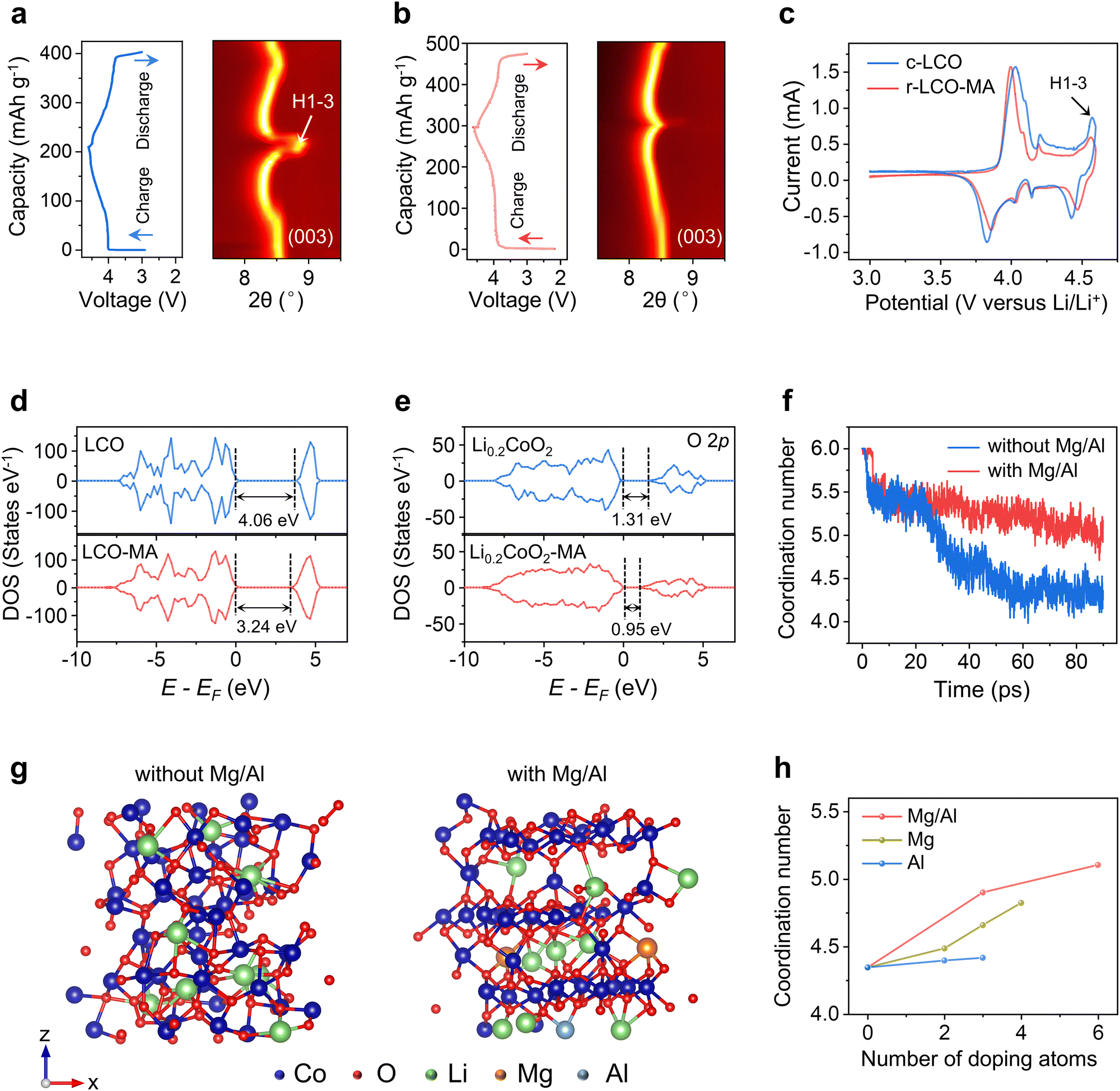 | ||
| Fig. 4 Mechanism of LCO structure stabilization by Mg/Al doping. (a) and (b) In situ XRD patterns of c-LCO and r-LCO-MA. (c) CV curves of c-LCO (blue line) and r-LCO-MA (red line). (d) Total DOS of LCO and LCO-MA. (e) pDOS of O 2p orbitals for Li0.2CoO2 with Mg/Al (left) or without Mg/Al (right). (f) Simulated variation of Co coordination in Li0.2CoO2 with Mg/Al doping (red line) or without Mg/Al doping (blue line). (g) Optimized structure snapshots of Li0.2CoO2 without Mg/Al doping (left) or with Mg/Al doping (right) with the simulation time of 90 ps. (h) Relationship of Co coordination number with dopants types and their contents. Al doping (blue line), Mg doping (dark yellow line), and Mg/Al co-doping (red line). | ||
To further explain the mechanism, density functional theory (DFT) and molecular dynamic (MD) simulations were employed. The simulation results revealed that doping atoms tend to occupy Li vacancies in the s-LCO with the lowest energy barrier (Fig. S49, ESI†). After Mg/Al doping, the charge density distribution of LCO is changed with a significantly reduced bandgap by 0.82 eV (Fig. 4d and e), which often leads to an improved conductivity and facilitated charge transfer, consisting with the reduced charge-transfer resistance in EIS spectra (Fig. 4f). Then, after 80% Li de-intercalation, fewer unoccupied O 2p orbitals in Li0.2CoO2 with lower energy were observed after Mg/Al doping (Fig. 4g and Note S3, ESI†), indicating the reduced charge transition probability and enhanced structural stability of oxygen atoms in the LCO lattice at high voltage. The electron density distribution of Co 3d orbitals also varies after Mg/Al doping (Fig. S50, ESI†), demonstrating the different Co chemical environments in Li0.2CoO2 and Li0.2CoO2-MA. The average Co coordination number was then calculated and applied as an indicator to evaluate the LCO stability after Li loss. In the initial LCO, Co3+ coordinates with six O2− to form an octahedron structure, while its coordination number tends to decrease to four after phase transformation. With the Mg/Al doping, Co can keep a high coordination number after Li loss with a maintained layered structure (Fig. 4f and g). In contrast, the Co coordination number in bare LCO rapidly decreases after Li loss with a degraded structure (Fig. 4f and g). It was also found that Mg/Al co-doping can keep a higher Co coordination number in LCO than Mg or Al single doping with the same doping content (Fig. 4h and Fig. S51, ESI†), proving co-doping can better facilitate LCO structural stability. With the increasing doping contents, the Co coordination number approaches 6 (Fig. 4h and Fig. S51, ESI†), demonstrating that higher doping contents facilitate a higher LCO stability.
Life cycle assessment and techno-economic analysis
To further evaluate the environmental footprints and the economic feasibility, we calculated the energy consumption of the RER process with 1.7 kW h to regenerate 1 kg of cathode (Note S4, ESI†), benefitting from the short heating duration, ultrafast heating/cooling rates, and high heating efficiency. Then, we compared our RER method with three traditional recycling processes, including hydrometallurgical, pyrometallurgical, and direct recycling by a comparative cradle-to-gate life cycle assessment (LCA) (Fig. 5a and Fig. S52, Note S5, Tables S5–S10, ESI†). The cumulative energy demand (CED) of RER is low to 9.0 MJ kg−1, which is 66% to 92% lower than other methods (Fig. 5b). RER also exhibits a 48% to 94% reduction in greenhouse gas (GHG) emission (Fig. 5c) and a 19% to 92% reduction in water consumption (Fig. 5d) without any other solvent consumption (Fig. 5e) compared to other methods. In addition, using the commercially available arc welder as the power source, the total cost to treat 1 kg of spent battery is low to $0.87, which is reduced by 42–87% compared with other methods (Fig. 5f). It was estimated that the RER method also makes an estimated profit of $18.8 kg−1 based on the high-voltage LCO cathode (Fig. 5f and Tables S11, S12, ESI†), which is 20–102% higher than other methods. With the merits of low cost, high efficiency, zero solvent use, and excellent cathode performance (Fig. 5g), the RER process shows potential superiorities over existing cathode recycling methods, showing an encouraging environmental and economic promise for practical applications (Fig. 5h). | ||
| Fig. 5 LCA and TEA assessments. (a) Materials flow of RER. The dashed rectangle denotes the system boundary. The numbers on the arrow denote the material flow mass in each step with the unit of kg. (b) Comparison of cumulative energy demand. (c) Comparison of cumulative GHG emissions. (d) Comparison of cumulative water consumption. (e) Comparison of cumulative solvent consumption. (f) Comparison of cost. (g) Comparison of profit. (h) Comprehensive comparison of different LCO recycling methods. | ||
Conclusions
In conclusion, we report an environmental and economical RER method to upcycle the spent LCO into a high-voltage cathode. Within a 30 s electrothermal process, the defective structure of spent LCO is restored with lithium relithiation. During this process, Mg and Al dopants diffused into LCO lattices, facilitating the cycling stability for the regenerated LCO under a high cut-off voltage of 4.6 V. With the low time- and energy consumption, low environmental impacts, and high efficiency, this process has the potential to be extended to upcycling other end-of-life battery materials. It is an attractive approach towards reducing dependence on metal mining and developing a circular battery manufacturing economy.Author contributions
Conceptualization: Y. C.; methodology: Y. C., J. C., W. C.; investigation: Y. C., J. C., W. C., Q. L., O. E. O, Z. W., G. W., T. X., and L. E.; writing – original draft: Y. C., J. C., and W. C.; writing – review & editing: Y. C., J. C., W. C., J. L., Y. Z., and J. M. T.; funding acquisition: Y. C., B. I. Y., Y. Z., J. M. T.; resources: J. L., Y. Z., B, I, Y., J. M. T.; and supervision: Y. C., J. L., Y. Z., and J. M. T.Data availability
The data supporting this article have been included as part of the ESI.†Conflicts of interest
Rice University owns intellectual property on the rapid electrothermal cathode upcycling strategy. A provisional patent was filed by Rice University, where Y. C. and J. M. T. are listed as the inventors. It has not yet been licensed. The authors declare no other competing interests.Acknowledgements
The authors thank Dr Bo Chen for the helpful discussion on XPS results, Dr Wenhua Guo for the assistance with TEM characterizations, Dr Jianhua Li for the temperature-dependent XRD test, and Dr Christopher Pennington for developing ICP-MS methods. The funding of the research is provided by Air Force Office of Scientific Research (FA9550-22-1-0526, J. M. T.), the U.S. Army Corps of Engineers, ERDC grant (W912HZ-21-2-0050, and W912HZ-24-2-0027, B. I. Y., Y. Z., J. M. T.), and Rice Academy Fellowship (Y. C.). Computational modeling (Y. Z. and B. I. Y.) resources were provided through allocation DMR100029 from the National Science Foundation ACCESS program. The characterization equipment used in this project is partly from the Shared Equipment Authority (SEA) at Rice University. The in situ XRD used in this project is from MIT.nano Characterization Facilities at Massachusetts Institute of Technology.Notes and references
- X. Xiao, L. Wang, Y. Wu, Y. Song, Z. Chen and X. He, Energy Environ. Sci., 2023, 16, 2856–2868 RSC.
- X. Yu, W. Li, V. Gupta, H. Gao, D. Tran, S. Sarwar and Z. Chen, Global Challenge, 2022, 6, 2200099 CrossRef PubMed.
- D. Song, J. Yu, M. Wang, Q. Tan, K. Liu and J. Li, Energy Storage Mater., 2023, 61, 102870 CrossRef.
- G. Semieniuk, L. Taylor, A. Rezai and D. K. Foley, Nat. Clim. Change, 2021, 11, 313–318 CrossRef.
- E. Fan, L. Li, Z. Wang, J. Lin, Y. Huang, Y. Yao, R. Chen and F. Wu, Chem. Rev., 2020, 120, 7020–7063 CrossRef CAS PubMed.
- G. Harper, R. Sommerville, E. Kendrick, L. Driscoll, P. Slater, R. Stolkin, A. Walton, P. Christensen, O. Heidrich and S. Lambert, Nature, 2019, 575, 75–86 CrossRef CAS PubMed.
- J. Wang, J. Ma, Z. Zhuang, Z. Liang, K. Jia, G. Ji, G. Zhou and H.-M. Cheng, Chem. Rev., 2024, 124, 2839–2887 CrossRef CAS PubMed.
- J. Baars, T. Domenech, R. Bleischwitz, H. E. Melin and O. Heidrich, Nat. Sustainable, 2021, 4, 71–79 CrossRef.
- K. Du, E. H. Ang, X. Wu and Y. Liu, Energy Environ. Mater., 2022, 5, 1012–1036 CrossRef CAS.
- S. Kalluri, M. Yoon, M. Jo, S. Park, S. Myeong, J. Kim, S. X. Dou, Z. Guo and J. Cho, Adv. Energy Mater., 2017, 7, 1601507 CrossRef.
- J. Qian, L. Liu, J. Yang, S. Li, X. Wang, H. L. Zhuang and Y. Lu, Nat. Commun., 2018, 9, 4918 CrossRef PubMed.
- J. Li, C. Lin, M. Weng, Y. Qiu, P. Chen, K. Yang, W. Huang, Y. Hong, J. Li, M. Zhang, C. Dong, W. Zhao, Z. Xu, X. Wang, K. Xu, J. Sun and F. Pan, Nat. Nanotechnol., 2021, 16, 599–605 CrossRef CAS PubMed.
- T. Fan, W. Kai, V. K. Harika, C. Liu, A. Nimkar, N. Leifer, S. Maiti, J. Grinblat, M. N. Tsubery and X. Liu, Adv. Funct. Mater., 2022, 32, 2204972 CrossRef CAS.
- J. Yao, Y. Li, T. Xiong, Y. Fan, L. Zhao, X. Cheng, Y. Tian, L. Li, Y. Li, W. Zhang, P. Yu, P. Guo, Z. Yang, J. Peng, L. Xue, J. Wang, Z. Li, M. Xie, H. Liu and S. Dou, Angew. Chem., Int. Ed., 2024, 136, e202407898 CrossRef.
- J.-N. Zhang, Q. Li, C. Ouyang, X. Yu, M. Ge, X. Huang, E. Hu, C. Ma, S. Li and R. Xiao, Nat. Energy, 2019, 4, 594–603 CrossRef CAS.
- Y. Huang, Y. Zhu, H. Fu, M. Ou, C. Hu, S. Yu, Z. Hu, C. T. Chen, G. Jiang, H. Gu, H. Lin, W. Luo and Y. Huang, Angew. Chem., Int. Ed., 2021, 60, 4682–4688 CrossRef CAS PubMed.
- N. Qin, Q. Gan, Z. Zhuang, Y. Wang, Y. Li, Z. Li, I. Hussain, C. Zeng, G. Liu and Y. Bai, Adv. Energy Mater., 2022, 12, 2201549 CrossRef CAS.
- M. Yoon, Y. Dong, Y. Yoo, S. Myeong, J. Hwang, J. Kim, S.-H. Choi, J. Sung, S. J. Kang, J. Li and J. Cho, Adv. Funct. Mater., 2020, 30, 1907903 CrossRef CAS.
- L. Yu, Y. Bai, R. Essehli, A. Bisht and I. Belharouak, Energy Storage Mater., 2023, 63, 103025 CrossRef.
- W. Lv, Z. Wang, H. Cao, Y. Sun, Y. Zhang and Z. Sun, ACS Sustainable Chem. Eng., 2018, 6, 1504–1521 CrossRef CAS.
- Y. Guo, C. Guo, P. Huang, Q. Han, F. Wang, H. Zhang, H. Liu, Y.-C. Cao, Y. Yao and Y. Huang, eScience, 2023, 3, 100091 CrossRef.
- J. Wang, K. Jia, J. Ma, Z. Liang, Z. Zhuang, Y. Zhao, B. Li, G. Zhou and H.-M. Cheng, Nat. Sustainable, 2023, 6, 797–805 CrossRef.
- P. Xu, D. H. Tan, B. Jiao, H. Gao, X. Yu and Z. Chen, Adv. Funct. Mater., 2023, 33, 2213168 CrossRef CAS.
- Y. Liu, B. Jiao, X. Guo, S. Li, X. Lou, F. Jiang, X. Weng, M. Cao, J. Chen, Q. Zhang, G. Wang, J. Di and P. Xu, Energy Storage Mater., 2024, 72, 103684 CrossRef.
- W. Zhu, J. Zhang, J. Luo, C. Zeng, H. Su, J. Zhang, R. Liu, E. Hu, Y. Liu, W.-D. Liu, Y. Chen, W. Hu and Y. Xu, Adv. Mater., 2023, 35, 2208974 CrossRef CAS PubMed.
- C. Wang, W. Ping, Q. Bai, H. Cui, R. Hensleigh, R. Wang, A. H. Brozena, Z. Xu, J. Dai, Y. Pei, C. Zheng, G. Pastel, J. Gao, X. Wang, H. Wang, J.-C. Zhao, B. Yang, X. Zheng, J. Luo, Y. Mo, B. Dunn and L. Hu, Science, 2020, 368, 521–526 CrossRef CAS PubMed.
- Y. Cheng, J. Chen, B. Deng, W. Chen, K. J. Silva, L. Eddy, G. Wu, Y. Chen, B. Li, C. Kittrell, S. Xu, T. Si, A. A. Martí, B. I. Yakobson, Y. Zhao and J. M. Tour, Nat. Sustainable, 2024, 7, 452–462 CrossRef.
- L. Wang, S. Zhu, Z. Huang, M. Li, Y. Zhao, G. Han, Y. Li and J. Ni, Adv. Funct. Mater., 2024, 27, 2401548 CrossRef.
- J. Luo, J. Zhang, Z. Guo, Z. Liu, C. Wang, H. Jiang, J. Zhang, L. Fan, H. Zhu, Y. Xu, R. Liu, J. Ding, Y. Chen and W. Hu, Adv. Mater., 2024, 36, 2405956 CrossRef CAS PubMed.
- W. Zhu, H. Su, P. Bai, Z. Li, J. Zhang, J. Zhang, M. Li, Y. Chen and Y. Xu, Chem. Eng. J., 2024, 480, 148045 CrossRef CAS.
- Y.-C. Yin, C. Li, X. Hu, D. Zuo, L. Yang, L. Zhou, J. Yang and J. Wan, ACS Energy Lett., 2023, 8, 3005–3012 CrossRef CAS.
- Y. Ji, H. Zhang, D. Yang, Y. Pan, Z. Zhu, X. Qi, X. Pi, W. Du, Z. Cheng, Y. Yao, L. Qie and Y. Huang, Adv. Mater., 2024, 36, 2312548 CrossRef CAS PubMed.
- T. Li, L. Tao, L. Xu, T. Meng, B. C. Clifford, S. Li, X. Zhao, J. Rao, F. Lin and L. Hu, Adv. Funct. Mater., 2023, 33, 2302951 CrossRef CAS.
- W. Chen, J. Chen, K. V. Bets, R. V. Salvatierra, K. M. Wyss, G. Gao, C. H. Choi, B. Deng, X. Wang, J. T. Li, C. Kittrell, N. La, L. Eddy, P. Scotland, Y. Cheng, S. Xu, B. Li, M. B. Tomson, Y. Han, B. I. Yakobson and J. M. Tour, Sci. Adv., 2023, 9, eadh5131 CrossRef CAS PubMed.
- W. Chen, Y. Cheng, J. Chen, K. V. Bets, R. V. Salvatierra, C. Ge, J. T. Li, D. X. Luong, C. Kittrell and Z. Wang, Nat. Commun., 2024, 15, 6250 CrossRef CAS PubMed.
- E. Fan, J. Lin, X. Zhang, R. Chen, F. Wu and L. Li, Small Methods, 2021, 5, 2100672 CrossRef CAS PubMed.
- Z. Fei, Y. Zhang, Q. Meng, P. Dong, J. Fei, S. Zhou and K. Kwon, ACS Sustainable Chem. Eng., 2021, 9, 11194–11203 CrossRef CAS.
- S. Zhou, Z. Fei, Q. Meng, P. Dong, Y. Zhang and M. Zhang, ACS Appl. Energy Mater., 2021, 4, 12677–12687 CrossRef CAS.
- N. Zhang, W. Deng, Z. Xu and X. Wang, Carbon Energy, 2023, 5, e231 CrossRef CAS.
- W. Kong, J. Zhang, D. Wong, W. Yang, J. Yang, C. Schulz and X. Liu, Angew. Chem., Int. Ed., 2021, 133, 27308–27318 CrossRef.
- Z. Wang, Z. Wang, H. Guo, W. Peng, X. Li, G. Yan and J. Wang, J. Alloys Compd., 2015, 621, 212–219 CrossRef CAS.
- J.-H. Shim, N.-H. Cho and S. Lee, Electrochim. Acta, 2017, 243, 162–169 CrossRef CAS.
- X. Z. Fan, J. H. Zhang, N. Yao, J. X. Chen, X. Chen and L. Kong, Adv. Energy Mater., 2024, 14, 2303336 CrossRef CAS.
- M. Yi, W. Li and A. Manthiram, Chem. Mater., 2022, 34, 629–642 CrossRef CAS.
- W. Cheng, M. Zhao, Y. Lai, X. Wang, H. Liu, P. Xiao, G. Mo, B. Liu and Y. Liu, Exploration, 2024, 4, 20230056 CrossRef CAS PubMed.
Footnote |
| † Electronic supplementary information (ESI) available. See DOI: https://doi.org/10.1039/d5ee00962f |
| This journal is © The Royal Society of Chemistry 2025 |