
 Open Access Article
 This Open Access Article is licensed under a Creative Commons Attribution-Non Commercial 3.0 Unported Licence
High-performance anode-less all-solid-state batteries enabled by multisite nucleation and an elastic network†
Jihoon
Oh‡
 ab,
Yeeun
Sohn‡
ab and
Jang Wook
Choi
*ab
ab,
Yeeun
Sohn‡
ab and
Jang Wook
Choi
*ab
aSchool of Chemical and Biological Engineering and Institute of Chemical Process, Seoul National University, 1 Gwanak-ro, Gwanak-gu, Seoul 08826, Republic of Korea. E-mail: jangwookchoi@snu.ac.kr
bHyundai Motor Group-Seoul National University (HMG-SNU) Joint Battery Research Center (JBRC), Seoul National University, Seoul, Republic of Korea
First published on 11th April 2025
Abstract
Anode-less all-solid-state batteries (ALASSBs) represent a promising energy storage platform for various upcoming green mobility applications, as they offer superior energy density, manufacturing feasibility, and enhanced safety. However, their practical implementation is hindered by the formation of heterogeneous lithium (Li) deposits during repeated cycling, particularly at ambient temperatures. In this study, we introduce a novel multi-seed strategy that integrates strategically distributed nucleation sites with a highly elastic and adhesive polymer matrix. The incorporation of multiple lithiophilic metallic seeds with a range of lithiation potentials promotes uniform Li deposition by facilitating diversified lithiation pathways. Simultaneously, the elastic polymer network enables stress dissipation across the protection layer, thereby effectively mitigating mechanical degradation. Even at room temperature (25 °C), the resulting anode-less full-cell retained 70% of its capacity after 100 cycles at a current density of 0.5C (1C = 2 mA cm−2). This study conveys a useful design principle for protective layers in ALASSBs: the advantageous synergistic effect created by combining multiple lithiophilic seeds with enlarged nucleation pathways and a stress-releasing elastic binder.
Broader contextAnode-less all-solid-state batteries (ALASSBs) represent a promising conceptual shift in energy storage. The anode-less architecture relies on the use of a bare current collector—and thus the absence of a dedicated lithium (Li) host material—on the anode side, which enhances the volumetric energy density while substantially reducing the costs. However, the widespread adoption of ALASSBs has been complicated by the difficulties associated with stabilizing Li (de)plating on the anode-less electrode under practical conditions. Conventional protective layers for anode-less systems have demonstrated effectiveness only under limited conditions, such as elevated temperatures. This study introduces an innovative multiple-seed architecture that utilizes strategically selected lithiophilic metals—magnesium (Mg), silver (Ag), and tin (Sn)—as distinct nucleation sites. These metals, with a wide range of lithiation potentials, enable controlled sequential lithiation pathways that promote uniform Li plating. We complement this multi-seed approach with a mechanically robust Elastane polymer network that effectively accommodates the volume changes the electrode experiences during Li plating–stripping cycles. This integrated architecture promotes stable operation at room temperature and suggests a new design principle for protecting the anode-side electrode of ALASSBs. |
1 Introduction
All-solid-state batteries (ASSBs)—a new competitive energy storage system for emerging mobility applications—represent a significant leap beyond their conventional liquid electrolyte-based lithium (Li)-ion battery (LIB) counterparts.1–4 By simultaneously offering both enhanced safety and high energy density, ASSBs have positioned themselves as frontrunners among next-generation rechargeable battery technologies.5–8 Central to this innovation is the development of solid electrolytes (SEs) with sulfide-based materials, which stand out due to their remarkable ionic conductivity and favorable mechanical properties.9–13Considerable effort has been dedicated to realizing the full potential of ASSBs with respect to the energy density at the battery cell level,14–16 particularly by focusing on the incorporation of advanced anode materials17,18 and the development of thin SE layers.19–21 Between these, the anode material plays a pivotal role in improving the volumetric energy density, and silicon (Si)-containing composites,22–25 Li metal foil,26–28 and even so-called anode-less designs have been identified as suitable options.29,30 The latter, in particular, represents a bold step forward by obviating the need for an active host for the storage of carrier ions as a way to maximize the energy density and push the boundaries of ASSB technology.31–33
In anode-less all-solid-state batteries (ALASSBs), in the absence of an active anode material, Li is deposited directly onto the anode current collector during charging. While this design offers notable advantages in terms of structural simplicity, along with maximizing the volumetric energy density, it also presents significant challenges in the form of spatially uneven Li (de)plating on the anode current collector, and this tends to evolve into indiscriminate Li dendritic growth.34,35 Attempts to address these issues have led to the implementation of thin protective layers, consisting of various components, on the current collector.36–38 These layers aim to maximize the energy density by minimizing the layer thickness while enabling reliable Li (de)plating over repeated cycles. A notable approach in this technological category thus far is the use of lithiophilic Li nucleation seeds, such as silver (Ag), in conjunction with the insertion of electrically conductive carbon components between the deposited Li and the SE.29 Despite this progress, designing protective layers that ensure reliable performance under practical operating conditions remains a formidable challenge. In this regard, the high energy barrier for Li diffusion into the protective layer constitutes a critical limitation, which—at moderate temperatures such as room temperature—promotes undesirable Li deposition in the subsurface (bulk) or surface regions of the protective structure.
To overcome this shortcoming, we designed a protective layer with the aim of actively promoting even Li (de)plating on the anode-less electrode. Specifically, we propose a multi-seed strategy that entails the combined use of three distinct lithiophilic metals: Ag, magnesium (Mg), and tin (Sn). These metallic seeds are integrated with a highly elastic polymeric binder, known as “Elastane” (Fig. 1a), to address the mechanical drawbacks associated with ALASSBs. Compared to conventional single-seed-based protective layers with standard binders (Fig. 1b), the proposed multi-seed approach leverages metals with varying lithiation potentials to promote uniform Li deposition through a continuous lithiation process over a range of different voltage windows. Additionally, the multiscale particle sizes of the different seeds effectively help to mitigate stress accumulation during cycling. The mechanical stability is further enhanced by the elastic recovery of the Elastane polymer (Fig. 1c), which dissipates mechanical stresses39 to ensure robust structural integrity. Our results show that this innovative approach significantly improves the performance of ALASSBs, thereby establishing a foundational design principle for anode-less seed layers.
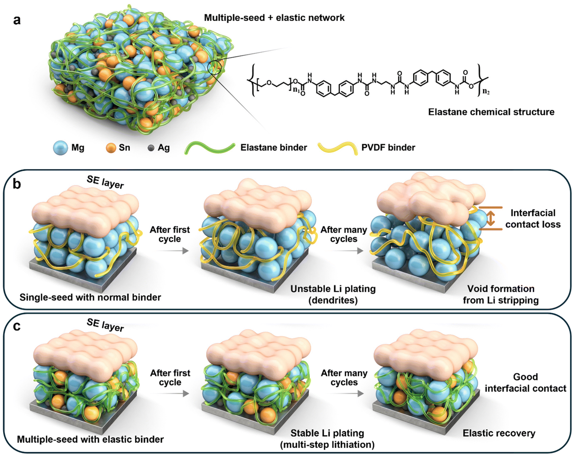 | ||
| Fig. 1 Schematic illustrations of the multiple-seed anode-less electrode. (a) Depiction of the MgAgSn electrode with the Elastane binder, including the chemical structure of the Elastane polymer. Morphological changes in the interface during electrochemical cycling with (b) a single-seed configuration using a standard PVDF binder and (c) a multiple-seed configuration using an Elastane binder. | ||
2 Results and discussion
2.1 Multi-seed strategy for stable Li plating
The operation of ALASSBs at suboptimal temperatures, particularly room temperature, is fundamentally challenging as a result of the substantial energy barriers for Li-ion diffusion that exist within the protective layer. Although monolayered lithiophilic metal seeds can to a certain extent overcome the temperature constraints through their inherent lithiophilicity, single-seed approaches often lead to spatially irregular Li deposition. This implies that single seeds may not be able to function sufficiently when the volume of Li being plated is much larger than the volume of the thin protection layer in ALASSB systems. This prompted our proposal of a multi-seed strategy that synergistically incorporates nucleation seeds with heterogeneous properties. Most notably, the distinctly different electrochemical potentials of these metallic seeds induce sequential Li deposition across different voltage ranges, and were expected to promote uniform and stable Li growth through continuous multistep nucleation. Furthermore, the graded nanoparticle sizes of the seeds were anticipated to enhance the mechanical integrity by allowing robust solid–solid contact. This physicochemical materials design effectively addresses both the kinetic limitations at room temperature and structural stability requirements for long-term operation.To evaluate the effectiveness of our multi-seed strategy, we compared the performance of multi-seed (MgAgSn) anode-less electrodes—comprising Mg (D50 = 800 nm), Ag (D50 = 30 nm), and Sn (D50 = 150 nm) nanoparticles—with their single-seed counterparts containing only Mg, Ag, or Sn, respectively. All these electrodes were fabricated with a uniform thickness of 5 μm using a slurry casting method incorporating the Elastane polymer. X-ray diffraction (XRD) analysis confirmed the crystalline structures of the Mg, Ag, and Sn nanopowders (Fig. S1, ESI†). Scanning electron microscopy (SEM) coupled with energy-dispersive X-ray spectroscopy (EDS) revealed the uniform distribution of the nanopowder particles in both single- and multi-seed configurations (Fig. S2–S5, ESI†).
Cross-sectional SEM-EDS analysis enabled us to additionally examine the Li plating morphology on the MgAgSn electrode, and demonstrated seamless contact between the solid constituents before (Fig. S6, ESI†) and after Li deposition (Fig. S7, ESI†). During the lithiation process, the three different metallic seeds engaged in sequential alloying reactions to form Li–Sn, Li–Mg, and Li–Ag alloys as the cell voltage decreased to 0 V vs. Li/Li+. Cyclic voltammetry (CV) analysis provided the signatures for this continuous lithiation behavior (Fig. S8, ESI†)40,41 by displaying the characteristic alloying peaks.
The electrochemical performances of the single- and multi-seed anode-less electrodes were assessed using half-cell configurations at room temperature (25 °C). The cells incorporated Li6PS5Cl (LPSCl)—a representative sulfide-based SE—and were cycled at a current density of 1 mA cm−2 with an areal capacity of 1 mA h cm−2 (Fig. 2). Among the electrodes, the MgAgSn multi-seed electrode exhibited the highest initial coulombic efficiency (ICE) of 84.5%, surpassing that of the single-seed electrodes of 68.5% (Mg), 76.2% (Ag), and 72.7% (Sn), respectively (Fig. 2a). Although the single-seed electrodes experienced early short-circuiting, the MgAgSn operated stably for over 230 cycles, with an average CE of 99.62% (Fig. 2b). The cumulative CE, calculated as the product of the CE values across all cycles,42,43 emphasized the superior reversibility of the MgAgSn electrode (Fig. 2c), which maintained excellent performance over 470 hours (Fig. 2d). This enhanced performance is attributed to the continuous, multistep lithiation process enabled by the seeds with distinct lithiation potentials, which successfully facilitated uniform Li deposition.44
 | ||
| Fig. 2 Half-cell Li plating–stripping evaluations of the single- and multi-seed anode-less electrodes. (a) Voltage profiles of the first cycle. (b) Coulombic efficiencies (CEs), (c) cumulative CEs, and (d) voltage–time profiles of the half-cells over cycling. | ||
Following Li plating–stripping cycling, the half-cells were analyzed by electrochemical impedance spectroscopy (EIS) (Fig. 3a–d) to assess the charge transport performance. The Nyquist plots based on these EIS measurements, in which the x-axis intercept corresponds to the bulk resistance (Rb), and the semicircle amplitude represents the charge transfer resistance (RCT),45–47 revealed that, as cycling progressed, the resistance values of the single-seed electrodes increased significantly. In contrast, the MgAgSn multiple-seed electrode consistently exhibited the lowest RCT values (Fig. 3e), demonstrating its superior stability throughout the Li plating–stripping process.48,49 Given that RCT in ASSB systems primarily stems from the loss of charge transport pathways due to the deterioration of contact between the solid components, the ability of our multiple-seed strategy to mitigate the resistance increase can be attributed to two key factors. First, the multistep lithiation process promoted more uniform Li deposition to prevent the formation of interfacial voids—a common cause of contact loss that emerges during the stripping of interfacial Li dendrites. Second, the multiscale seed configuration, with its varied particle sizes, enabled a more efficient spatial arrangement, thereby improving the solid–solid interfacial contact.
 | ||
| Fig. 3 Half-cell EIS analysis after Li plating–stripping. Nyquist plots and the corresponding equivalent circuits of the (a) Mg, (b) Ag, (c) Sn, and (d) MgAgSn half-cells after 5 and 10 cycles of Li plating–stripping. (e) Charge transfer resistance (RCT) values extracted from the EIS data. | ||
2.2 Elastane polymer as a stress-dissipating network
The impact of the elastic polymer network was evaluated by comparing the performance between the Elastane polymer and the conventional polyvinylidene fluoride (PVDF) binder. Elastane (Fig. S9, ESI†) is a representative polyurethane39 that consists of repeating urethane bonds formed through an addition polymerization reaction between alcohols with active hydroxyl groups (–OH) and isocyanates (–N![[double bond, length as m-dash]](https://www.rsc.org/images/entities/char_e001.gif) CO). Fourier transform infrared spectroscopy (FT-IR) analysis confirmed the chemical structure of the Elastane polymer (Fig. S10, ESI†). The hard and soft segments of Elastane enable it to effectively accommodate large volume changes during charging and discharging, owing to its superior elasticity. Nano-indentation tests demonstrated the exceptional elastic recovery of the Elastane (Fig. S11, ESI†).
CO). Fourier transform infrared spectroscopy (FT-IR) analysis confirmed the chemical structure of the Elastane polymer (Fig. S10, ESI†). The hard and soft segments of Elastane enable it to effectively accommodate large volume changes during charging and discharging, owing to its superior elasticity. Nano-indentation tests demonstrated the exceptional elastic recovery of the Elastane (Fig. S11, ESI†).
To assess the binding characteristics, the polymer films were subjected to a 180-degree peel-off test (Fig. S12, ESI†). The results indicated a load of 20 gf mm−1 for the Elastane, compared to a negligible load of approximately 2 gf mm−1 for the PVDF. The application of each binder to the MgAgSn electrode, followed by peel-off testing, further confirmed the superior adhesion of the Elastane-based layer (Fig. S13, ESI†). This suggests successful intermolecular interactions between the metal nanoparticle surfaces in the MgAgSn and the polar substituents of Elastane. Post-peel-off test examination of the electrode surfaces (Fig. S14, ESI†) revealed that the protective layer was completely removed in the case of PVDF, whereas the Elastane electrode remained intact. These results indicate that the robust binding affinity of Elastane effectively plays a key role in suppressing mechanical instabilities arising from the volumetric expansion of thick Li deposits, which accumulate during successive charge–discharge cycling.
In a subsequent evaluation of the adhesion properties of the binders, a scratch test was conducted on the MgAgSn anode-less electrodes (Fig. 4a–f). This test involved progressively increasing the scratch force across a defined electrode area, while simultaneously profiling the penetration depth and optically observing the deformed region. For the electrode with Elastane (Fig. 4a), negligible penetration depths were observed in the initial range from 0 to 0.5 mm (section 1), with minimal electrode damage, as confirmed by optical imaging (Fig. 4b). However, in section 2 (1.5 mm to 2.0 mm), where a relatively stronger force was applied, significant penetration depths and extensive scratching were observed (Fig. 4c). In contrast, the PVDF electrode exhibited markedly different behavior. Early in section 1, substantial penetration depths were observed (Fig. 4d), suggesting lower mechanical stability compared to the Elastane electrode. Post-scratch imaging confirmed considerable electrode damage (Fig. 4e), and larger penetration depths were noted in section 2, with a narrow, deep penetration area (Fig. 4f). These distinct behaviors can be attributed to the following: the Elastane polymer network, with its high elasticity, efficiently distributes the applied stress over the surrounding area, whereas the rigidity of PVDF leads to localized, deep scratch deformation. These findings point to the fact that the Elastane polymer effectively mitigates localized mechanical damage associated with volume changes during Li plating–stripping cycles.
 | ||
| Fig. 4 Scratch and nano-indentation analysis of the MgAgSn anode-less electrodes. (a–f) Scratch test results and visual documentation. (a) Penetration depth profiles and (b and c) optical micrographs of the scratched electrode with the Elastane binder. Section 1 corresponds to the 0–0.5 mm distance range, whereas section 2 represents 1.5–2.0 mm. (d) Penetration depth profiles and (e and f) optical micrographs of the scratched electrode with the PVDF binder. (g–i) Nano-indentation test results. (g) Force–time curves during the indentation. (h and i) Force-depth profiles of the indentation with the (h) Elastane and (i) PVDF binders. | ||
Nano-indentation analysis of the MgAgSn electrodes provided additional information on their elasticity (Fig. 4g–i). The Elastane-based electrode exhibited a 1000 nm penetration depth at a lower load (Fig. 4g, dotted circles), indicative of its relatively soft nature. Notably, during the final stage of deloading, the Elastane-based electrode exhibited steep depth recovery arising from the elasticity of the Elastane (Fig. 4h), whereas the PVDF electrode underwent no such recovery (Fig. 4i). These results reconfirm the effect of the stress-absorbing capabilities of Elastane owing to its superior elasticity.
Subsequent in situ EIS analysis enabled us to quantify the resistance during the half-cell Li plating–stripping process. Li plating was executed for a period of 1 hour at a current density of 1 mA cm−2 (1 mA h cm−2), followed by a stripping process, with EIS measurements performed in 10-minute intervals. The EIS measurement sequence was categorized into Li plating sequences 1–6 and Li stripping sequences 1–5 (Fig. 5a and b).
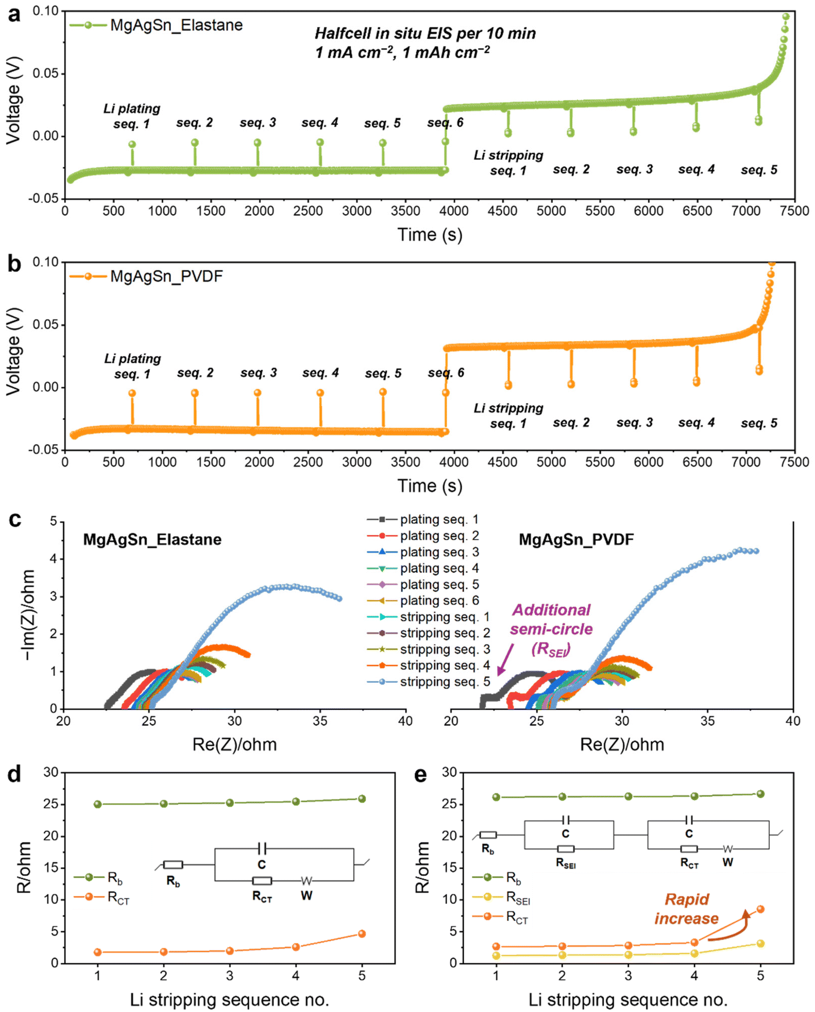 | ||
| Fig. 5 In situ EIS analysis during Li plating–stripping in the half-cell. (a and b) Voltage profiles during the EIS measurements of the MgAgSn half-cells with the (a) Elastane and (b) PVDF binders. (c) Nyquist plots representing the EIS results. (d and e) Resistance values and corresponding equivalent circuit models used for EIS data fitting of the MgAgSn half-cells with the (d) Elastane and (e) PVDF binders. | ||
The resulting Nyquist plots revealed significant disparities (Fig. 5c); particularly, the appearance of an additional semicircle in the high-frequency region corresponded to the solid electrolyte interphase (SEI) resistance (RSEI) in the PVDF binder system. This is suggestive of substantial SEI formation, resulting from increased physical contact between the uneven Li dendrites and the SE. Additionally, the larger semicircle corresponding to RCT observed for the PVDF binder during the final Li stripping sequence was ascribed to more pronounced void formation at this stage. Data fitting using distinct equivalent circuits (insets of Fig. 5d and e) confirmed a more significant increase in resistance with the PVDF binder during both Li plating (Fig. S15, ESI†) and stripping (Fig. 5d and e). The in situ EIS analysis conclusively corroborated that the Li plating–stripping behavior is largely influenced by the elasticity of the binder network.
2.3 Full-cell performance with high-voltage cathodes
Extensive half-cell cycling tests were conducted to assess the long-term performance of the MgAgSn electrodes with the two different binders. The results indicated a notable improvement in both the CE and cycle life with Elastane (Fig. 6a). In view of the anode-less configuration, reversibility is a crucial factor for prolonging the full-cell lifetime.50 These findings strongly suggest that the elastic network plays a pivotal role in optimizing the performance of anode-less systems.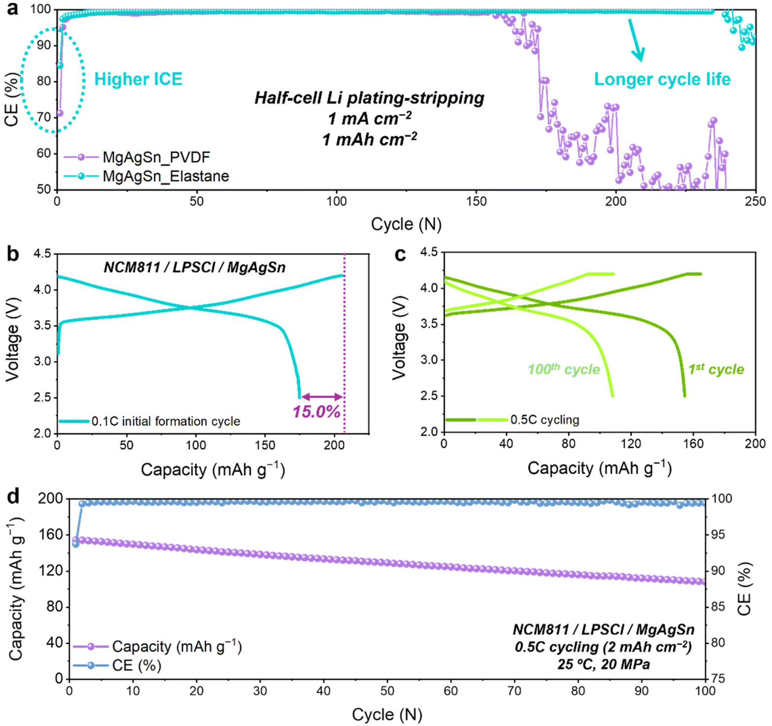 | ||
| Fig. 6 Half-cell and full-cell performances of the MgAgSn anode-less electrodes. (a) CE comparison during Li plating–stripping tests in half-cells. (b–d) Full-cell performance of the MgAgSn anode-less electrodes with the Elastane binder, paired with an NCM811 cathode: (b) voltage profile during the initial 0.1C formation cycle; (c) voltage profiles and (d) cycling performance at 0.5C (1C = 2 mA cm−2). | ||
Cross-sectional SEM-EDS analysis after 50 cycles of Li plating–stripping revealed substantial contact loss between the MgAgSn and SE layer with the PVDF binder (Fig. S16, ESI†). In contrast, the Elastane elastic network preserved stable interfacial contact to demonstrate enhanced structural integrity (Fig. S17, ESI†). This phenomenon primarily stems from the elastic recovery of the Elastane network, which crucially contributes to alleviating the negative stress induced during Li stripping. Considering that maintaining solid–solid contact is essential for the reliable operation of ASSB cells, this mechanism holds particular significance. Moreover, enhancement of the mechanical stability presents a promising strategy for lowering the stack pressure required for the practical operation of these cells. Consequently, beyond elasticity, polymeric binders within anode-less protective layers must concurrently exhibit robust adhesion properties to counteract interfacial decoupling caused by electrode volume fluctuations. A strategic design approach involves engineering copolymer architectures—mimicking the hard–soft segment topology of Elastane—where polar functional groups are densely integrated into the hard segments. This molecular configuration synergizes elastic recovery with strong interfacial adhesion, effectively mitigating mechanical degradation induced by dynamic volume changes during cycling.
Full-cell evaluations were conducted using the Elastane-based MgAgSn electrode paired with a high-voltage layered cathode, specifically LiNbO3-coated LiNi0.8Co0.1Mn0.1O2 (NCM811). The cell had a high ICE of 85% (Fig. 6b) and successfully cycled for 100 cycles at 0.5C (1C = 2 mA cm−2) without significant deformation (Fig. 6c). Consistent with the aforementioned half-cell evaluations, these results confirmed that the multiple-seed protective layer, composed of MgAgSn and Elastane, achieves excellent reversibility and stability. This is particularly decisive in full-cells, where the limited supply of Li is exclusively provided by the cathode in each cycle. The ALASSB cell based on the MgAgSn multi-seeds and the Elastane binder retained 70% of its original capacity after 100 cycles at room temperature (Fig. 6d). Rate capability evaluation further revealed stable operation at current densities up to 1C (2 mA cm−2) (Fig. S18, ESI†), indicating the adaptability of the proposed strategy in practical full-cell operations.
3 Conclusions
In summary, we introduced an innovative strategy that involves combining the seeds of multiple lithiophilic metals with a highly elastic adhesive polymer matrix to enhance the room-temperature performance of ALASSBs. The integration of these multisized seed particles with their diverse lithiation potential ranges facilitated continuous, uniform Li deposition while effectively alleviating the stresses generated during cycling. Moreover, the incorporation of polymeric Elastane amplified the protective capability of this system by creating a resilient network. These combined approaches significantly improved the mechanical stability of the anode–SE interface, a crucial factor governing the longevity and efficiency of ALASSBs. The strategy successfully overcomes the operational temperature constraints of the conventional protective layers in ALASSBs to achieve stable cycling with 70% capacity retention over 100 cycles at room temperature. Our investigation established useful design principles for protective layers in the development of high-performance ALASSBs.Data availability
The data supporting the findings of this study are available within the article and its ESI.† Additional datasets generated and analyzed during the current study are available from the corresponding author on reasonable request. No software or code have been included as part of this study.Conflicts of interest
The authors declare no competing interests.Acknowledgements
J. W. C. acknowledges support from the Swiss National Science Foundation (SNF) (grant no. Sinergia CRSII5_202296), the National Research Foundation of Korea (NRF) (RS-2023-00261543 and RS-2024-00464386), the Korea Institute of Machinery and Materials (KIMM) (grant no. NK243H), and generous support from the Institute of Engineering Research (IOER), the Institute for Battery Research Innovation (IBRI), and Research Institute of Advanced Materials (RIAM) at Seoul National University. This work was also supported by Hyundai Motor Company.References
- J. Oh, S. H. Choi, H. Kim, J. Y. Kim, G.-J. Lee, K. Y. Bae, T. Lee, N. Lee, Y. Sohn, W. J. Chung and J. W. Choi, Energy Environ. Sci., 2024, 17, 7932–7943 RSC.
- A. Manthiram, X. Yu and S. Wang, Nat. Rev. Mater., 2017, 2, 16103 CrossRef CAS.
- J. Xie and Y.-C. Lu, Nat. Commun., 2020, 11, 2499 CrossRef CAS.
- M. Armand and J.-M. Tarascon, Nature, 2008, 451, 652–657 CrossRef CAS PubMed.
- Q. Zhao, S. Stalin, C.-Z. Zhao and L. A. Archer, Nat. Rev. Mater., 2020, 5, 229–252 CrossRef CAS.
- J. Janek and W. G. Zeier, Nat. Energy, 2023, 8, 230–240 CrossRef.
- J. Janek and W. G. Zeier, Nat. Energy, 2016, 1, 16141 CrossRef.
- R. Van Noorden, Nature, 2014, 507, 26 CrossRef CAS PubMed.
- J. Oh, W. J. Chung, S. H. Jung, Y. Kim, Y. Lee, Y. J. Nam, S. Lee, C. H. Kim and J. W. Choi, Energy Storage Mater., 2024, 71, 103606 CrossRef.
- N. Kamaya, K. Homma, Y. Yamakawa, M. Hirayama, R. Kanno, M. Yonemura, T. Kamiyama, Y. Kato, S. Hama and K. Kawamoto, Nat. Mater., 2011, 10, 682–686 CrossRef CAS PubMed.
- Y. Kato, S. Hori, T. Saito, K. Suzuki, M. Hirayama, A. Mitsui, M. Yonemura, H. Iba and R. Kanno, Nat. Energy, 2016, 1, 1–7 Search PubMed.
- A. Kuhn, V. Duppel and B. V. Lotsch, Energy Environ. Sci., 2013, 6, 3548 RSC.
- Y. Seino, T. Ota, K. Takada, A. Hayashi and M. Tatsumisago, Energy Environ. Sci., 2014, 7, 627 RSC.
- S. Randau, D. A. Weber, O. Kötz, R. Koerver, P. Braun, A. Weber, E. Ivers-Tiffée, T. Adermann, J. Kulisch and W. G. Zeier, Nat. Energy, 2020, 5, 259–270 CrossRef CAS.
- Y.-S. Hu, Nat. Energy, 2016, 1, 1–2 Search PubMed.
- J.-M. Tarascon and M. Armand, Nature, 2001, 414, 359–367 CrossRef CAS PubMed.
- P. Oh, J. Yun, J. H. Choi, K. S. Saqib, T. J. Embleton, S. Park, C. Lee, J. Ali, K. Ko and J. Cho, Angew. Chem., Int. Ed., 2022, 61, e202201249 CrossRef CAS PubMed.
- J. A. Lewis, K. A. Cavallaro, Y. Liu and M. T. McDowell, Joule, 2022, 6, 1418–1430 CrossRef CAS.
- J. Wu, L. Yuan, W. Zhang, Z. Li, X. Xie and Y. Huang, Energy Environ. Sci., 2021, 14, 12–36 RSC.
- X. Yang, K. R. Adair, X. Gao and X. Sun, Energy Environ. Sci., 2021, 14, 643–671 RSC.
- A. Müller, L. Paravicini, J. Morzy, M. Krause, J. Casella, N. Osenciat, M. H. Futscher and Y. E. Romanyuk, ACS Appl. Mater. Interfaces, 2024, 16, 1 CrossRef.
- T. Lee, M. J. Seong, H. C. Ahn, M. Baek, K. Park, J. Oh, T. Choi and J. W. Choi, Proc. Natl. Acad. Sci. U. S. A., 2025, 122, e2417053121 CrossRef CAS PubMed.
- W. Yan, Z. Mu, Z. Wang, Y. Huang, D. Wu, P. Lu, J. Lu, J. Xu, Y. Wu and T. Ma, Nat. Energy, 2023, 8, 800–813 CrossRef CAS.
- S. Choi, T.-W. Kwon, A. Coskun and J. W. Choi, Science, 2017, 357, 279–283 CrossRef CAS PubMed.
- C. Cao, I. I. Abate, E. Sivonxay, B. Shyam, C. Jia, B. Moritz, T. P. Devereaux, K. A. Persson, H. G. Steinrück and M. F. Toney, Joule, 2019, 3, 762 CrossRef CAS.
- L. Braks, J. Zhang, A. Forster, P. Fritz, J. Oh, M. El Kazzi, J. W. Choi and A. Coskun, Angew. Chem., 2024, 136, e202408238 CrossRef.
- L. Ye, Y. Lu, Y. Wang, J. Li and X. Li, Nat. Mater., 2024, 23, 244–251 CrossRef CAS PubMed.
- W. Xu, J. Wang, F. Ding, X. Chen, E. Nasybulin, Y. Zhang and J. G. Zhang, Energy Environ. Sci., 2014, 7, 513 RSC.
- Y.-G. Lee, S. Fujiki, C. Jung, N. Suzuki, N. Yashiro, R. Omoda, D.-S. Ko, T. Shiratsuchi, T. Sugimoto and S. Ryu, Nat. Energy, 2020, 5, 299–308 CrossRef CAS.
- K. Yan, Z. Lu, H.-W. Lee, F. Xiong, P.-C. Hsu, Y. Li, J. Zhao, S. Chu and Y. Cui, Nat. Energy, 2016, 1, 1 Search PubMed.
- N. Lee, J. Oh and J. W. Choi, Mater. Futures, 2023, 2, 013502 CrossRef CAS.
- Y. Qiao, H. Yang, Z. Chang, H. Deng, X. Li and H. Zhou, Nat. Energy, 2021, 6, 653–662 CrossRef CAS.
- S. Nanda, A. Gupta and A. Manthiram, Adv. Energy Mater., 2021, 11, 2000804 CrossRef CAS.
- J. Oh, S. H. Choi, J. Y. Kim, J. Lee, T. Lee, N. Lee, T. Lee, Y. Sohn, W. J. Chung, K. Y. Bae, S. Son and J. W. Choi, Adv. Energy Mater., 2023, 13, 2301508 CrossRef CAS.
- S. E. Sandoval, C. G. Haslam, B. S. Vishnugopi, D. W. Liao, J. S. Yoon, S. H. Park, Y. Wang, D. Mitlin, K. B. Hatzell and D. J. Siegel, Nat. Mater., 2025, 1–9 Search PubMed.
- J. Lee, S. H. Choi, G. Im, K. J. Lee, T. Lee, J. Oh, N. Lee, H. Kim, Y. Kim, S. Lee and J. W. Choi, Adv. Mater., 2022, 34, 2203580 CrossRef CAS PubMed.
- S. E. Sandoval, J. A. Lewis, B. S. Vishnugopi, D. L. Nelson, M. M. Schneider, F. J. Q. Cortes, C. M. Matthews, J. Watt, M. Tian, P. Shevchenko, P. P. Mukherjee and M. T. McDowell, Joule, 2023, 7, 9 CrossRef.
- Y. Wang, Y. Liu, M. Nguyen, J. Cho, N. Katyal, B. S. Vishnugopi, H. Hao, R. Fang, N. Wu and P. Liu, Adv. Mater., 2023, 35, 2206762 CrossRef CAS PubMed.
- J. Oh, S. H. Choi, B. Chang, J. Lee, T. Lee, N. Lee, H. Kim, Y. Kim, G. Im, S. Lee and J. W. Choi, ACS Energy Lett., 2022, 7, 1374–1382 CrossRef CAS.
- H.-Y. Chiu, Y.-C. Liu, Y.-T. Hsieh and I.-W. Sun, ACS Omega, 2017, 2, 4911–4919 CrossRef CAS PubMed.
- B. Li, F. Yao, J. J. Bae, J. Chang, M. R. Zamfir, D. T. Le, D. T. Pham, H. Yue and Y. H. Lee, Sci. Rep., 2015, 5, 1–9 Search PubMed.
- M. C. Schulze and N. R. Neale, ACS Energy Lett., 2021, 6, 1082–1086 CrossRef CAS.
- C. Wang, F. Yang, W. Wan, S. Wang, Y. Zhang, Y. Huang and J. Li, Energy Environ. Sci., 2023, 16, 4660–4669 RSC.
- Y. Sohn, J. Oh, J. Lee, H. Kim, I. Hwang, G. Noh, T. Lee, J. Y. Kim, K. Y. Bae, T. Lee, N. Lee, W. J. Chung and J. W. Choi, Adv. Mater., 2024, 36, 2407443 CrossRef CAS PubMed.
- N. Lee, J. Lee, T. Lee, J. Oh, I. Hwang, G. Seo, H. Kim and J. W. Choi, ACS Appl. Mater. Interfaces, 2023, 15, 34931–34940 CrossRef CAS PubMed.
- E. J. Cheng, Y. Kushida, T. Abe and K. Kanamura, ACS Appl. Mater. Interfaces, 2022, 14, 40881–40889 CrossRef CAS PubMed.
- P. Vadhva, J. Hu, M. J. Johnson, R. Stocker, M. Braglia, D. J. Brett and A. J. Rettie, ChemElectroChem, 2021, 8, 1930 CrossRef CAS.
- H. K. Tian and Y. Qi, J. Electrochem. Soc., 2017, 164, E3512 CrossRef CAS.
- A. Parejiya, R. Amin, M. B. Dixit, R. Essehli, C. J. Jafta, D. L. Wood III and I. Belharouak, ACS Energy Lett., 2021, 6, 3669–3675 CrossRef CAS.
- J. Oh, D. Kwon, S. H. Choi, N. Lee, Y. Sohn, T. Lee, T. Lee, J. Y. Kim, K. Y. Bae and J. W. Choi, Adv. Energy Mater., 2024, 2404817 CrossRef.
Footnotes |
| † Electronic supplementary information (ESI) available. See DOI: https://doi.org/10.1039/d5eb00050e |
| ‡ These two authors contributed equally to this work. |
| This journal is © The Royal Society of Chemistry 2025 |