
 Open Access Article
 This Open Access Article is licensed under a Creative Commons Attribution-Non Commercial 3.0 Unported Licence
Equal resistance single and bilayer films decouple role of solid electrolyte interphase from lithium morphology in batteries†
Sanzeeda Baig
Shuchi‡
 a,
Kenzie M.
Sanroman Gutierrez‡
a,
Alexander B.
Shearer
a,
Solomon T.
Oyakhire
a,
Yi
Cui
*bcd and
Stacey F.
Bent
*ac
a,
Kenzie M.
Sanroman Gutierrez‡
a,
Alexander B.
Shearer
a,
Solomon T.
Oyakhire
a,
Yi
Cui
*bcd and
Stacey F.
Bent
*ac
aDepartment of Chemical Engineering, Stanford University, Stanford, California 94305, USA. E-mail: sbent@stanford.edu
bDepartment of Materials Science and Engineering, Stanford University, Stanford, California 94305, USA. E-mail: yicui@stanford.edu
cDepartment of Energy Science and Engineering, Stanford University, Stanford, California 94305, USA
dStanford Institute for Materials and Energy Sciences, SLAC National Accelerator Laboratory, 2575 Sand Hill Road, Menlo Park, California 94025, USA
First published on 2nd April 2025
Abstract
The solid electrolyte interphase (SEI) is one of the most crucial but least understood performance modulators in lithium metal batteries (LMBs). However, decoupling the effect of interfacial chemistries on the formation of the SEI from the lithium (Li) metal morphology remains a challenge. Here, we develop a platform to control Li morphology independent of the interfacial properties by depositing different metal oxide films of fixed resistance on Cu substrates. While the fixed resistance of the films ensures an analogous, resistance-controlled Li morphology, the different film chemistries result in distinctive chemical compositions of the SEI. Our results show that for a fixed morphology of Li, SEI becomes the key performance determinant, wherein a more stable SEI results in an increased battery cycle life. Moreover, we decouple the importance of the two relevant interfaces—that between the Cu/thin film and between the thin film/electrolyte—by using binary stacks of metal oxide thin films. Our stacked film design establishes the dominance of the thin film/electrolyte interface in controlling behavior for cells with fixed Li morphology. This thin film/electrolyte interface controls both the SEI composition and battery performance, i.e., stack designs containing the same top film result in similar SEI compositions and cycling performance trends in LMBs where Li morphology is fixed. Specifically, by switching the thin film/electrolyte interface to Al2O3, significant improvements in cycling stability were observed with coulombic efficiencies above 80% up to ∼130 cycles in carbonate electrolytes.
Broader contextOne of the most promising next-generation battery technologies is the lithium metal battery (LMB) due to its large energy density. However, the high reactivity of lithium causes major issues like dendritic lithium morphology and continuous solid electrolyte interphase (SEI) growth, accelerating the failure of these battery systems. Interface engineering of the Cu current collector can be useful to tune the lithium morphology and SEI by exploiting thin film properties like resistance and film acidity. Here, we present an interface engineering framework in which equal resistance single and binary stacked films are used for tuning SEI while holding the lithium morphology fixed. We leverage atomic layer deposition (ALD) to modify the Cu current collector and achieve nanoscale precision of film thickness and film chemistry. We present several new thin film coatings and a unique design of binary stacked films for Cu modification that all outperform bare Cu to different degrees due to their different SEI compositions. Fundamentally, our systematic interface engineering approach to understand the impact of an individual SEI chemistry while fixing lithium morphology using thin films can be useful in batteries and in other energy storage devices. |
1. Introduction
With an increasing reliance on renewable energy and battery-powered technologies, high energy-density and high-performing batteries are needed to support reliable energy storage, long-range electric vehicles, and modern consumer devices. Lithium-ion batteries (LIBs) with graphite anodes have been the staple; however, energy density advancements have been slow, and at gravimetric energy densities of around 250 W h kg−1, graphite-based LIBs are approaching their practical limit.1 Lithium–metal batteries (LMBs) are a promising next-generation battery with high theoretical energy densities (ex: Li–S, 2567 W h kg−1).2 Lithium (Li) metal also offers high gravimetric capacities (3860 mA h g−1) and low reduction potentials (−3.04 V vs. S.H.E.).2 Yet, developments in LMBs have been limited by various issues, including the corrosion of the highly reactive Li metal and the formation of high surface area, inhomogeneous Li deposits, known as dendrites, at the anode.2,3Two properties that significantly affect the performance of the LMBs are the composition of the solid electrolyte interphase (SEI) and the morphology of the Li deposited at the anode.4 The SEI is formed from decomposed electrolyte and Li and is a Li-ion conducting, chemically passivating layer at the anode–electrolyte interface. While passivation provided by the SEI can improve cycle life, the SEI can be fractured by deposited Li, leading to hot spots for Li metal dendrite growth and the associated electrolyte consumption to form new SEI. Thus, SEIs that are mechanically robust, electrochemically stable, and homogeneous are favored. Studies have shown that such SEIs are attained via the incorporation of inorganic species primarily derived from the anion of the salt in the electrolyte.5–10
With each cycle, Li electrodeposits on the anode current collector and its morphology evolves. Low surface area Li deposits are beneficial because they limit the interaction between the Li metal and the electrolyte, preventing adverse reactions between Li and electrolyte.11 Additionally, dense and homogenous Li deposits are preferred because they prevent localized ion fluxes that can perpetuate SEI fracturing, generate dendrite growth, and produce electronically isolated Li/dead Li.12 Thus, various methods have been employed to control the morphology of the Li deposition including electrolyte engineering,9,13,14 stable host design,15–18 and surface engineering. Furthermore, surface engineering has been leveraged to improve Li deposition via the use of lithiophilic and reactive surfaces amongst other routes.19–22 Particularly, the application of atomic layer deposition (ALD) and molecular layer deposition (MLD), two techniques that use sequential and self-limiting gas–surface reactions to form conformal and uniform thin films, have been applied to change the interfacial properties of batteries and create surfaces conducive to the formation of dense and compact Li deposits.23–25 Interfacial coatings deposited using ALD have also been utilized to modulate SEI decomposition reactions.26–28 ALD deposited interfacial films thus present a unique opportunity to regulate reactions at key interfaces that influence SEI composition, Li deposition, and electron transfer to provide a deeper understanding of fundamental battery operation, as well as suggest new avenues for improving performance.
Counterintuitive to the general concept of nucleation, our group has shown that ALD-grown, electrically resistive thin films support the growth of dense low surface area Li deposits on the Cu current collector resulting in major performance benefits in LMB systems.4,29 Although the resistive films impede electron transfer, defects in the film create areas of low resistance. It has been hypothesized that these low resistance defects behave like ultramicroelectrodes and encourage radial diffusion of Li ions to the nuclei, promoting lateral growth and producing low surface area, dense, and planar Li deposits.30 The resistive thin film coatings increase the first-cycle Li nucleation overpotential, making the electrical resistance of the current collector a critical Li morphology modulator, and allowing first-cycle Li nucleation overpotential to serve as a proxy of the resistance measurement. Regarding the practical applicability of resistive thin film coatings, previous research from our group on singular resistive films, including Al2O3 and HfO2, also confirms improved cycling performance in practical anode-free pouch cells.4,29
In the present work, we take advantage of the morphological control that electrical resistance provides to explore the impact of interfacial properties on the SEI composition and the performance of the LMB. This uniquely allows us to understand the impact of SEI composition during kinetic regimes that are typically convoluted by both Li nucleation and SEI growth. Previous studies have focused on extreme cases of morphological control, including ultrafast deposition when electrodeposition is favored over SEI growth,31,32 or by contrasting interfaces with drastically different morphologies.33 We instead explore the convoluted regime present at moderate current densities by creating resistive films of equal resistance, but of different thicknesses and different metal oxides, to maintain a constant 1st cycle Li nucleation overpotential and hence fix the Li nucleation morphology. Holding constant the Li nucleation morphology allows us to explore the impact of thin film chemistry on the SEI. We use ALD to modify the Cu current collector with sub-20 nm resistive thin films, including materials that have been previously applied to interfacial anode modification, such as Al2O3 and HfO2, as well as introducing the use of ZrO2 and AlHfxOy. Aside from creating conformal and uniform thin films, ALD allows us to have effective control over the thin film thickness to ensure fixed resistance. We show through scanning electron microscopy (SEM) results that all cells modified with resistive metal oxide films exhibit resistance-fixed Li nucleation morphology. However, long-term cycling tests reveal differences in cell performance and life cycle.
Through the use of X-ray photoelectron spectroscopy (XPS), we investigate the relative abundance of inorganic species in the SEI, as well as the anion-derived nature of the SEI. We show through a compilation of XPS data that the composition of the SEI is tuned by the surface chemical properties of the thin film. Specifically, each metal oxide has a unique affinity to electrolyte species, which consequently alters electrolyte decomposition and incorporation into the SEI. Additionally, we conduct separate XPS analyses on three types of samples to investigate the SEI composition: 1. on thin film-modified Cu before Li deposition, 2. atop the thin film and Li deposits after the initial Li deposition cycle, and 3. only above the deposited Li by ensuring a high deposition capacity. This analysis confirms that the metal oxide thin film tunes the SEI composition. Furthermore, we create a set of binary stacked metal oxide thin films that maintain the fixed resistance while flipping the stack order. Investigating the Li nucleation morphology, SEI composition, and LMB performance with this sample set allows for deconvolution of the impact of the Cu/thin film interface and thin film/electrolyte interface. The application of stacked interfacial films allows for an improved understanding of the role of the Cu/thin film interface which participates in electron exchange reactions. Based on our fixed-resistance and binary stack experimental design, we propose that modulation of the SEI composition by the metal oxide controls LMB performance when the Li nucleation morphology is fixed. The generalizability of our concepts is established using eight different interfaces.
2. Results and discussion
2.1. Design platforms to investigate role of the SEI for a fixed Li morphology
In order to delineate the impact of the SEI on battery performance, we must disentangle the influence of Li morphology. Because previous studies29 have shown a clear correlation between interfacial resistance and Li morphology, we can separate the contribution from Li morphology by designing a platform that holds interfacial resistance fixed while allowing the chemistry at the electrode interface to be varied. We achieve this desired platform by depositing onto the Cu current collector a sequence of metal oxide (MOx) interfacial films in which the resistance is held constant (as determined by a fixed nucleation overpotential) but the identity of the metal oxide in contact with the electrolyte is varied. We use two different designs, illustrated in Fig. 1, to hold MOx resistance approximately constant but vary the MOx/electrolyte interface. In the first design (Fig. 1a), we deposit metal oxides of different resistivities, such as HfO2 and Al2O3, but select film thicknesses that are inversely proportional to their resistivity to produce films with the same resistance. In the second design (Fig. 1b), we deposit binary stacks of metal oxides but swap the order, so that resistance stays constant but the MOx in contact with the electrolyte changes. This latter configuration also allows us to vary the Cu/MOx interface along with the MOx/electrolyte interface to probe for any effect of the former. | ||
| Fig. 1 Design concept for investigating the role of the SEI while having fixed Li morphology obtained with equal resistance thin films. (a) Illustration of variation of film chemistry to vary the SEI. (b) Illustration of using binary stacks of MOx films to understand and decouple the roles of the Cu/thin film and the thin film/electrolyte interface. (c) Illustration of films with the same thin film/electrolyte interface producing a similar SEI regardless of the Cu/thin film interface. | ||
2.2. Varying thickness of resistive thin films and resulting performance impact
For design 1, we chose Al2O3, HfO2, and AlHfxOy to investigate different resistive thin film chemistries. Since previous studies29 showed that 8 nm thick Al2O3 was the thinnest layer that could improve battery performance, we chose an 8 nm Al2O3 thin film coating on the Cu current collector as the first model metal oxide system in this work. We then varied the thickness of the other two metal oxides, HfO2, and AlHfxOy, until we achieved a similar nucleation overpotential as Al2O3. As established in earlier resistive thin film work, there is a direct correlation between nucleation overpotential and thin film resistance, since increased resistance impedes electron transfer requiring a higher overpotential to nucleate on the thin film surface.29 Nucleation overpotential can thus be used as a proxy for thin film resistance, and a fixed nucleation overpotential can indicate that Li nucleation is similarly constrained across the resistive films. Because Li nucleation is limited to defect sites in the resistive film, we expect that the morphology will be correlated with the resistance of the thin film.The results of the nucleation overpotential measurements are plotted in Fig. 2a, which shows evidence that statistically equivalent Li nucleation overpotentials could be obtained with the selected resistive thin films. A thicker HfO2 thin film (13 nm) than Al2O3 was required, which is consistent with the known electrical resistivity of Al2O3 (∼1016 Ω cm) and HfO2 (∼1014 Ω cm).4,29,34,35 For AlHfxOy, an intermediate thickness was required (10 nm). We also characterized the thin films using XPS (data shown in ESI Fig. 1 and 2†) and results show the presence of all expected metallic peaks (Al 2p and Hf 4f) for the respective metal oxides. The ratio of oxygen to metal is slightly higher than stoichiometrically expected; however, this can be attributed to the formation of carbon-oxygen bonds present in adventitious carbon.
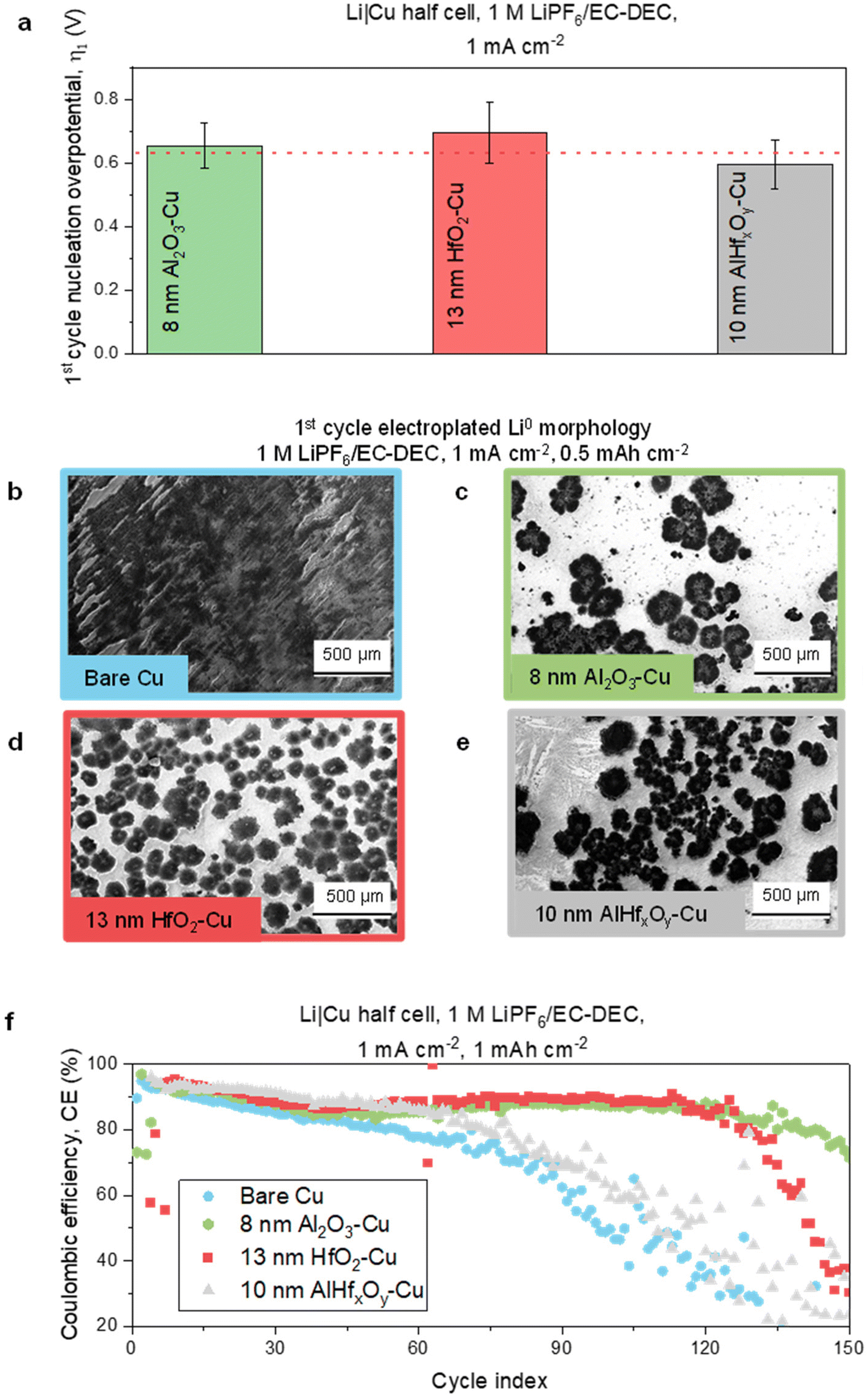 | ||
| Fig. 2 1st cycle Li nucleation overpotential, electrodeposited Li morphology, and Li|Cu half-cell cycling performance with bare Cu and different resistive thin films modified-Cu current collectors. (a) 1st cycle Li nucleation overpotential with 8 nm Al2O3–Cu, 13 nm HfO2–Cu, and 10 nm AlHfxOy–Cu. The error bars are calculated from three different cells. Thin film-coated Cu substrates were randomly selected from different ALD runs. 1st cycle electroplated Li0 morphology measured by SEM at 0.5 mA h cm−2 capacity on (b) bare Cu, (c) 8 nm Al2O3–Cu, (d) 13 nm HfO2–Cu, and (e) 10 nm AlHfxOy–Cu. (f) Long-term cycling performance as reported in CE with bare Cu, 8 nm Al2O3–Cu, 13 nm HfO2–Cu, and 10 nm AlHfxOy–Cu. Experiments in a, b, and c are performed in Li|Cu half-cells using 1 M LiPF6/EC–DEC electrolyte at 1 mA cm−2 current density. | ||
Fig. 2b–e shows the Li morphology measured by SEM after 1st cycle electroplating at 0.5 mA h cm−2 capacity on the bare, 8 nm Al2O3-, 13 nm HfO2-, and 10 nm AlHfxOy-modified Cu current collectors. All three of the resistive thin films promote low surface area, sparse Li deposits (Fig. 2c–e). In contrast, on the bare Cu current collector, the Li deposits (Fig. 2b) exhibit high surface area and extensive surface coverage. These results are similar to our previous reports and indicate the successful formation of resistance-derived Li morphology on the ALD-coated substrates.29 Magnified versions of these morphology images are shown in ESI Fig. 3.† We note that the Li particle size distribution (PSD) differs among these substrates (ESI Fig. 4†), but the Li morphology trend is similar overall. While we strive for consistency with the experiments, many parameters can impact the detailed PSD, e.g., coin cell pressure, spatial positioning during imaging, and thin film defect density variations from batch to batch during thin film deposition. To confirm the relationship in morphology across the three different MOx films, we also ran experiments depositing a lower capacity of Li, and the three different resistance-controlled substrates again showed very similar Li morphology (ESI Fig. 5†).
Despite similarities in the Li morphology, the performance is not the same for the different MOx films. Fig. 2f shows the cycling performance of Li|Cu half-cells with bare, 8 nm Al2O3-, 13 nm HfO2-, and 10 nm AlHfxOy-modified Cu. Replicates of battery cycling performance tests are presented in ESI Fig. 6.† The results show that even with the statistically similar Li nucleation overpotential and resistance-controlled Li morphology, the cycle life varies for the different thin film coatings, and it follows the following trend: 8 nm Al2O3–Cu > 13 nm HfO2–Cu > 10 nm AlHfxOy–Cu > Bare Cu. From this trend, we hypothesize that there might be differences in the SEI composition causing differences in cycle life. In the following sections, we design and discuss experiments validating this hypothesis.
2.3. Variation in the SEI for the fixed-resistance thin films
Since the fixed-resistance thin films lead to comparable resistance-derived Li morphology yet different cycling performance, we investigate the SEI chemical composition variations on different substrates and their correlation with performance. It is important to note that the carbonate-based electrolyte used in these studies is known to create an organic-rich SEI at the Li/electrolyte interface.26 However, we expect the average SEI composition to be impacted by the resistive substrates underlying the Li for the following reasons. First, SEI formation can occur prior to Li nucleation. Second, because the resistive thin films cause the formation of sparse Li deposits atop Cu substrates, the exposed resistive film will still be exposed to the electrolyte in many areas and hence can impact the decomposition of electrolyte due to its surface chemistry. The result should indicate SEI species modulation during cycling.To fully understand the SEI composition and deconvolve the role of the MOx thin film from that of the Li surface on controlling average SEI composition, we perform interfacial studies by XPS with three different protocols, illustrated in Fig. 3a, d, and i. In protocol (i), which corresponds to Fig. 3a, we seek the contribution of only the MOx thin film on the SEI by forming the SEI prior to the onset of Li nucleation via a potential hold above the Li electrodeposition potential, 10 mV vs. Li/Li+ for 3 h (Fig. 3a–d). In protocol (ii), which corresponds to Fig. 3e, we probe the contribution of both the MOx thin film-modified Cu and Li on the SEI composition by measuring the SEI after a brief first cycle plating of 0.5 mA h cm−2 Li at a current density 1 mA cm−2 (Fig. 3e–h). Protocol (ii) is more likely to represent actual cycling conditions because due to the sparse Li deposits, we are probing the average SEI composition from the contribution of both the Li and MOx thin film. Finally, in protocol (iii), which corresponds to Fig. 3i, we explore the contribution of only the Li by forming the SEI atop Li after a full first plating of 2 mA h cm−2 Li at a current density 1 mA cm−2 (Fig. 3i–l).
 | ||
Fig. 3 SEI chemical composition analysis using XPS following different protocols to probe the anion-derived nature (F/C, P/C ratio), and stability (relative LiF amount) of SEI. (a) Schematic illustration of XPS sampling area of the SEI formed by protocol (i) prior to the onset of Li nucleation, using a potential hold above the Li electrodeposition potential, 10 mV vs. Li/Li+ for 3 h. XPS results analyzing the SEI created in protocol (i) showing (b) the F/C and P/C atomic ratios for the three different MOx films, with the P/C range set at 1/6 of the F/C range to facilitate comparison with the 1![[thin space (1/6-em)]](https://www.rsc.org/images/entities/char_2009.gif) :6 ratio of P:F in LiPF6; (c) the F 1s high resolution (HR) scan for the 8 nm Al2O3–Cu sample; and (d) the F 1s HR scan for the 10 nm AlHfxOy–Cu sample. (e) Schematic illustration of XPS sampling area of the SEI formed by protocol (ii) after first cycle plating of 0.5 mA h cm−2 Li at a current density 1 mA cm−2. (f–h) Show the corresponding F/C and P/C atomic ratios and F 1s HR scans for protocol (ii) (i) Schematic illustration of XPS sampling area of SEI formed by protocol (iii) atop Li after first plating of 2 mA h cm−2 Li at a current density 1 mA cm−2. (j–l) Show the corresponding F/C and P/C atomic ratios and F 1s HR scans for protocol (iii). :6 ratio of P:F in LiPF6; (c) the F 1s high resolution (HR) scan for the 8 nm Al2O3–Cu sample; and (d) the F 1s HR scan for the 10 nm AlHfxOy–Cu sample. (e) Schematic illustration of XPS sampling area of the SEI formed by protocol (ii) after first cycle plating of 0.5 mA h cm−2 Li at a current density 1 mA cm−2. (f–h) Show the corresponding F/C and P/C atomic ratios and F 1s HR scans for protocol (ii) (i) Schematic illustration of XPS sampling area of SEI formed by protocol (iii) atop Li after first plating of 2 mA h cm−2 Li at a current density 1 mA cm−2. (j–l) Show the corresponding F/C and P/C atomic ratios and F 1s HR scans for protocol (iii). | ||
For the XPS studies of the SEI, we mainly focus on two criteria: first, the F/C and P/C ratios to determine the anion-derived nature of the SEI, and second, F 1s high-resolution scans to understand the relative content of LiF. A higher F/C and P/C ratio would indicate more anion-decomposition from the salt (LiPF6) during SEI formation, resulting in a more salt-derived, or anion-derived, SEI.14 The relative content of LiF can be a useful indicator of SEI stability since LiF is considered a beneficial inorganic compound in the SEI.36–38 Literature suggests that grain boundaries among LiF help uniform Li+ ion diffusion across the SEI resulting in uniform Li deposition.38In situ LiF-rich SEIs are shown to have faster SEI repair kinetics facilitating smooth Li deposition.36 Between the F/C ratio and relative LiF content criteria, the F/C and P/C ratios are prioritized first in our analysis. Then, for SEIs with similar F/C and P/C ratios (signifying their inorganic-rich or organic-rich nature), the relative amount of LiF is used to understand SEI stability. We follow this sequence to avoid any misinterpretations around SEI stability, because an analysis region with a low F concentration but a higher relative amount of LiF from the F 1s peak may lead to a lower absolute LiF amount than a region which has a high F concentration but a lower relative amount of LiF from F 1s peak. Fig. 3 shows the F 1s high-resolution scans of SEI formed on 8 nm Al2O3–Cu and 10 nm AlHfxOy–Cu, while the associated supporting high-resolution scans of SEI formed on HfO2–Cu are shown in ESI Fig. 7.†
We first discuss Fig. 3a–d, which measures the contribution of only the MOx thin film to the SEI formation (protocol i). Since no Li deposition occurs at this voltage, Li does not cover any surface of the Cu substrates, and we can understand the impact of the metal oxide/electrolyte interface in the absence of electrodeposited Li. We believe the low relative amount of LiF for these samples is consistent with this protocol since there is no Li electrodeposition and thus, less Li at the surface available to react with the electrolyte and form LiF.39 We also find for this protocol that the F/C and P/C ratios for AlHfxOy are lower than those for Al2O3 and HfO2 (Fig. 3b), suggesting that the SEI with AlHfxOy coating is less anion-derived. Being organic-rich, AlHfxOy would thus promote the least stable SEI, which may explain the comparatively worse cycling performance observed for AlHfxOy-modified Cu (Fig. 2f). Fig. 3c and d show in the high-resolution F 1s scan that the relative LiF content is higher for AlHfxOy-coated Cu than for Al2O3–Cu; however, after accounting for the lower overall F/C ratio for AlHfxOy–Cu, the actual LiF/C ratio on AlHfxOy–Cu is shown to be lower than on Al2O3–Cu (ESI Table 1†), suggesting a more stable SEI for the latter.
The next protocol, protocol (ii), is the most representative of the actual cycling conditions because it is performed under similar conditions as experienced during cycling. Moreover, since sparse Li deposits are formed with resistive substrates, this experiment should show the impact of both the thin MOx film and Li in the SEI formation. The results are shown in Fig. 3e–h. Fig. 3f shows that the average F/C ratios follow a trend Al2O3–Cu > HfO2–Cu > AlHfxOy–Cu, although the differences are slighter than what is observed in Fig. 3b. We speculate that the lower degree of variation in F/C and P/C ratios in Fig. 3f than that of Fig. 3b is caused by incorporation of sparse Li deposits into the analysis. This scenario likely occurs because Li regions would induce the same SEI composition regardless of different modified copper substrates at the Li–electrolyte interface. We also observe a significantly higher proportion of LiF for protocol (ii) than for protocol (i) due to the presence of deposited Li. Within protocol (ii), the relative amount of LiF is higher for Al2O3–Cu than for AlHfxOy–Cu (Fig. 3g and h). This increased LiF may support the observed improved cycle life for Al2O3–Cu.
Finally, to understand the impact of only the Li surface on SEI species control, we perform an experiment with twice the deposition capacity of cycling and probe the SEI atop the Li (protocol iii). ESI Fig. 8† shows different high-resolution scans in the metal peak regions to confirm that the scans are from the regions where the probed surface is Li, i.e., no metal peaks from the underlying MOx thin films are observed in the scanning area. The results of the XPS scans for protocol (iii) are shown in Fig. 3j–l. As expected, there is no statistically significant difference among the F/C and P/C ratios measured in this experiment with different resistive substrates (Fig. 3j) because the SEI composition for this case represents predominantly the Li–electrolyte interactions. Since the F/C ratios are statistically similar, we carefully analyze the F 1s peak to find further differences in relative LiF amount. We find that a higher LiF content is observed in the Al2O3-coated Cu substrate compared to AlHfxOy–Cu (Fig. 3k and l). Although Fig. 3j–l capture the impact of Li only, a higher relative amount of LiF on Al2O3–Cu may suggest that the Al2O3–Cu SEI would be more stable than that of AlHfxOy–Cu.
Our results indicate that with the tested protocols to understand the SEI composition, compared to AlHfxOy, both Al2O3 and HfO2 thin films lead to SEIs with the types of compositions typically associated with better stability. These composition features include more anion-derived SEI as measured by F/C and P/C ratios, as well as a higher proportion of F present as LiF species. This composition analysis helps explain the relative battery cycle improvement with Al2O3–Cu and HfO2–Cu when compared to the other resistive thin film of AlHfxOy–Cu. Moreover, since protocol (ii) is the most representative of the actual cycling conditions and captures the contributions of both Li and resistive MOx films on SEI formation, for subsequent parts of the study we investigate the SEI using protocol (ii). We speculate that different surface chemistry properties of the thin films such as surface charge, charge density, as well as thin film deposition conditions may impact the electrolyte decomposition. The C 1s high-resolution scans of the SEIs with protocol (ii) for different substrates are shown in ESI Fig. 9.† Furthermore, to verify our argument on SEI stability, we characterize the residual SEI after the 40th stripping for our best-performing Al2O3 films and bare Cu. Expectedly, major differences are not observed in SEI atomic ratios (ESI Fig. 10a†) but are found in the F 1s high-resolution scans (ESI Fig. 10b†). We find a higher relative LiF content on Al2O3–Cu compared to bare Cu substrates (ESI Fig. 10c†). These results on SEI composition are consistent with our conclusions from the initial cycle SEI characterization.
We find that both Fig. 3b and j show statistically similar values for the F/P stoichiometric ratio near ∼6. For the case of Fig. 3f, where both electrodeposited Li and thin film influence the salt decomposition, an off-stoichiometric F/P ratio is observed for Al2O3 and AlHfxOy interfaces. We speculate that this is due to the heterogeneity at the surface where electrodeposited Li and thin films alter the kinetics of salt decomposition differently. For Li, it is due to the electrochemical and chemical decomposition of the salt8 whereas, for the metal oxides the acidity of the thin films influences the salt decomposition.2
2.4. Varying the binary stacking order of resistive thin films and resulting SEI composition and performance
To better understand how the SEI composition is regulated by the metal oxide/electrolyte interface and to explore the impact of other interfaces, we employed design 2, in which two different ALD-grown metal oxides are stacked on the Cu current collector as described in Fig. 1b. Stacking the binary layered films allows for deconvolution of the impacts of the Cu/thin film interface and thin film/electrolyte interface on SEI composition and performance. For this design, we explored three different resistive MOx films: HfO2, Al2O3, and ZrO2. We introduce ZrO2-modified films to add another point for comparison. The thin film characterization for ZrO2-modified Cu substrates using XPS can be found in ESI Fig. 11,† and cycling performance test results, Li nucleation morphology, and SEI composition for the ZrO2 samples are included in ESI Fig. 12.† The XPS results show the presence of the metallic Zr peaks, as well as an O:Zr ratio that is slightly above what is stoichiometrically expected. The cycling performance using ZrO2 coatings (ESI Fig. 12a†) is better than bare Cu but worse than the Cu coated with Al2O3 and HfO2, with long-term coulombic efficiencies falling below 80% at 100–120 cycles. The SEM images (ESI Fig. 12b†) confirm the Li morphology remains of low surface area and planar, while the XPS high-resolution F 1s spectrum of the SEI (ESI Fig. 12d†) confirms a relatively low ratio of LiF to other fluorinated species. This result reveals that despite the Li morphology remaining similar due to the fixed resistance, the chemical nature of ZrO2 produces a lower SEI quality and thus poorer cycling performance. The thin film characterization for the binary stack thin films on Cu using XPS can be found in ESI Fig. 13–15.† The XPS spectra confirm that the relevant metallic peaks (Al 2p, Hf 4f, and Zr 3d) are present in the stacked films.
The thickness of each of the stacked films was selected to provide a nucleation overpotential fixed near the same value, as shown in Fig. 4a. Each half of the stack contained 4 nm Al2O3, 6.5 nm HfO2, or 8.5 nm ZrO2, respectively, which correspond to half of the thickness used in the 1st cycle nucleation overpotential experiments as shown in Fig. 2a and 4a. The Li deposition across the series of stacked films continued to show low surface area, planar, resistance-fixed morphology as shown in the SEM images in ESI Fig. 16.† This is reasonable, as our goal here is to grow thin films with equal resistance, resulting in the overall similar resistance-fixed Li morphology. We note that differences in morphology can exist due to variations in coin cell pressure distribution, spatial positioning when imaging, and thin film defect density across batches. The SEI compositions of cells modified with each of the binary MOx stacks, as well as the single metal oxide films, were measured using XPS. The results of the F/C ratios are presented in Fig. 4b, sorted according to their thin-film electrolyte interface. For example, Al2O3, Al2O3 on HfO2, and Al2O3 on ZrO2 all have the Al2O3 surface exposed to the electrolyte and to highlight that they form one related class of samples, their bars are positioned in front of the green background. In the F/C ratios, statistically significant differences are not observed for most films. To be specific, only two of the top-performing films, Al2O3–Cu and Al2O3 on HfO2–Cu, show a statistically significant difference with the worst-performing AlHfxOy–Cu. Other interesting observations are that cells with the same metal oxide/electrolyte interface have similar trends in F/C ratios. For example, cells with Al2O3/electrolyte interfaces have the highest F/C ratios on average, while cells with HfO2/electrolyte interfaces have large variances in the F/C ratio (bars positioned in front of red background). This result suggests that the SEI structure and chemical composition may be influenced by the thin film/electrolyte interface.
 | ||
| Fig. 4 1st cycle nucleation overpotentials, F/C atomic ratios of the SEI, and F 1s HRs scans of the SEI for the binary MOx stacked films. (a) 1st cycle Li nucleation overpotential of cells modified with the stacked binary metal oxide coatings. The error bars are calculated from three different cells each. Thin film coated Cu substrates were randomly selected from different ALD runs. (b) F/C atomic ratio of SEI including cells modified with the stacked binary metal oxide coatings with protocol (ii). F 1s HR scan of SEI formed using protocol (ii) on (c) Al2O3 on HfO2–Cu (d) HfO2 on Al2O3–Cu (e) Al2O3 on ZrO2–Cu and (f) ZrO2 on Al2O3–Cu. | ||
Since the F/C ratios themselves are not very conclusive, to gain a deeper understanding of the system, we have studied and analyzed the high-resolution XPS scans. The high-resolution F 1s peaks reveal that the ratio of the LiF peak to the C–F/LixPFyOz peak matches best with the high-resolution F 1s spectra of other films with the same metal–oxide electrolyte interface (Fig. 4c–f) as evident in the Al2O3-containing interfaces. High-resolution F 1s spectra of the SEI of HfO2–Cu and ZrO2–Cu cells can be found in ESI Fig. 7b and 12d.† Cells with Al2O3/electrolyte interfaces have a high LiF to C–F/LixPFyOz ratio, while those with HfO2/electrolyte interfaces have a similar LiF to C–F/LixPFyOz ratio, and those with ZrO2/electrolyte interfaces have a low LiF to C–F/LixPFyOz ratio. This corroborates that SEI composition is highly tuned by the thin film/electrolyte interface.
Long-term cycling performance tests were conducted on the cells modified with stacked thin films to explore the impact of the Cu current collector-thin film interface and thin-film electrolyte interface, as well as the aggregate stack composition, on the cell's performance and cycle life. The long-term cycling tests reveal that cells with the same metal oxide/electrolyte interface have similar performance regardless of the buried metal oxide-current collector interface (Fig. 5). A table identifying key performance parameters for each modified cell, including average CE for cycles 5–50 and the cycle index at which the cell drops below 80% CE, are reported in Table 1. The most notable differences are exemplified by the Al2O3 and ZrO2 stacked set. While the cells with the Al2O3/electrolyte interface have an average CE for cycles 5–50 of 84.9 (±1.5)–87.6 (±1.0), cells with the ZrO2/electrolyte interface have a statistically different average CE of 78.6 (±1.6)–79.0 (±0.2). Looking at more long-term performance trends, cells with the Al2O3/electrolyte interface maintain CE above 80% until cycles 114 (±43.3)–134 (±6.6) (Fig. 5a), while cells with the ZrO2/electrolyte interface see CEs of <80% by 8.0 (±1.4)–11.8 (±7.5). The much lower values for the ZrO2/electrolyte interfaces could reflect a more fragile SEI that requires more cycles to stabilize. At higher cycle indices, cells with the ZrO2/electrolyte interface experience rapid drops in CE at 90–120 cycles (Fig. 5c), indicating less long-term stability than cells with Al2O3/electrolyte or HfO2/electrolyte interfaces. The long-term performance tests for the stacked thin films are each verified by at least two replicates which can be found in ESI Fig. 17.† Moreover, ESI Fig. 18† shows the comparison of CE data versus cycle index for the same material stacks (HfO2 on Al2O3versus Al2O3 on HfO2) and (ZrO2 on Al2O3versus Al2O3 on ZrO2) confirming that while the cycling behavior is similar for the same MOx/electrolyte interface, it is not the same if the stack order is switched.
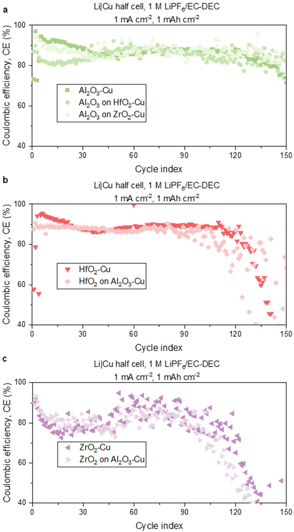 | ||
| Fig. 5 Comparative long-term cycling performance between batteries with the same thin film/electrolyte interface. Long-term cycling performance for metal oxide-modified Cu with cells containing a (a) Al2O3/electrolyte interface, (b) HfO2/electrolyte interface, and (c) ZrO2/electrolyte interface. Experiments are performed in Li|Cu half-cells using 1 M LiPF6/EC–DEC electrolyte at 1 mA cm−2 current density. | ||
| Film | Average CE cycles 5–50 | Average CE cycles 50–80 | Average CE cycles 5–80 | Cycle before falling below 80% for two consecutive cycles after cycle 5 |
|---|---|---|---|---|
| Al2O3 | 87.6 ± 1.0 | 86.0 ± 5.9 | 87.0 ± 0.6 | 134 ± 6.6 |
| Al2O3 on ZrO2 | 85.9 ± 2.2 | 86.2 ± 1.2 | 86.1 ± 1.7 | 114 ± 43.3 |
| Al2O3 on HfO2 | 84.9 ± 1.5 | 86.7 ± 1.5 | 85.6 ± 0.5 | 121.3 ± 29.4 |
| HfO2 | 86.0 ± 3.3 | 87.7 ± 1.4 | 86.7 ± 2.5 | 124.3 ± 6.4 |
| HfO2 on Al2O3 | 88.2 ± 0.3 | 91.7 ± 5.8 | 89.7 ± 2.5 | 117 ± 9.6 |
| ZrO2 | 79.0 ± 0.2 | 86.8 ± 0.4 | 82.1 ± 0.1 | 8 ± 1.4 |
| ZrO2 on Al2O3 | 78.0 ± 1.6 | 78.1 ± 7.8 | 78.0 ± 3.9 | 11.8 ± 7.5 |
| AlHfxOy | 90.1 ± 0.4 | 83.3 ± 0.8 | 87.4 ± 0.1 | 65.3 ± 11.6 |
To show how SEI composition can impact cycling performance and SEI stability at later cycles, we include the voltage profiles for cycles 140–150 for cells modified with Al2O3–Cu, Al2O3 on ZrO2–Cu, and ZrO2 on Al2O3-Cu in ESI Fig. 19.† Al2O3–Cu has a very stable voltage profile that is similar to that of Al2O3 on ZrO2–Cu. Since resistance and morphology are similar, this suggests the enhanced SEI at the Al2O3/electrolyte interface supports performance and stabilization even at 150 cycles. Al2O3 on ZrO2–Cu and ZrO2 on Al2O3–Cu have the same thickness and resistance but differing thin film/electrolyte interfaces. ZrO2 on Al2O3–Cu presents more instabilities reaffirming that differences in initial SEI, as confirmed by XPS, impact late-cycle stability.
To understand more about SEI stability using single and bilayer stack films, we perform electrochemical impedance spectroscopy (EIS) analysis of Li|Cu cells with electrodeposited Li for both ZrO2 and Al2O3 on ZrO2 modification (ESI Fig. 20†). We find that cells with Al2O3 on ZrO2 have a higher initial SEI impedance compared to ZrO2. We also observe a similar trend from our SEI chemical composition results where a higher average F/C ratio and a higher relative LiF content are observed with Al2O3/electrolyte interfaces. The trend can be rationalized with the high charge transfer resistance at the Li and resistive Al2O3 interface and the insulating nature of LiF causing a higher SEI resistance value consistent with previous findings on LiF-rich SEIs.10 After 25 hours, a similar degree of increase in SEI resistance (∼200%) is observed with both films. This increase in SEI resistance mainly occurs from chemical SEI growth due to Li-electrolyte reactions.15 Since Li undergoes severe calendar aging and high SEI growth in the carbonate-based electrolyte, a similar degree of SEI resistance increase is observed.15 So, for this case, we believe that the SEI growth is mostly driven by electrolyte diffusion towards the surface of Li.
Our stacked film experiments clearly demonstrate that the thin film/electrolyte interface controls the SEI composition and subsequently tunes the cycling performance. These results are significant because they help decouple the impacts of the buried Cu/thin film and the exposed thin film/electrolyte interfaces. Whereas the SEI and cycling performance correlate with the thin film/electrolyte interface, we observe no strong correlation of either SEI or cycling performance with the buried Cu/thin film interface (ESI Fig. 21†). We postulate that the MOx present at the Cu current collector/thin film interfaces could impact electron transport, and thus the nucleation and subsequent growth of the Li deposit.29,40,41 However, the cycling performance results show that the chemical composition of the MOx at the thin film/electrolyte interface plays a dominant role due to its ability to tune the SEI composition. This result emphasizes the importance of SEI composition on the overall performance of the battery for similar types of Li morphology. Nevertheless, it is important to consider that the dominant factor for overall performance control appears to be the thin film resistance, whereas the MOx thin film chemistry is only a secondary factor. This study intentionally removed this effect by studying MOx thin films of equal resistance.
We note that although the cells modified with stacked films do behave similarly to cells with unstacked films that have the same thin-film electrolyte interface, the stacked films exhibited higher instability compared to the non-stacked films. This is further explored in the voltage profiles for cycles 140–150 shown in ESI Fig. 19.† Although the Al2O3–Cu and Al2O3 on ZrO2–Cu samples have similar interfaces and similar voltage profiles, the Al2O3 on ZrO2–Cu sample does have some subtle instabilities, for example at around hour 273. A previous study has shown that stacked films of Al2O3/HfO2/Al2O3, with each layer being 20 nm, grown using ALD on stainless steel and titanium, led to the formation of agglomerates at the interlayers possibly interfering with the stability of the thin film.42 This could explain why, despite seeing similar coulombic efficiency trends, there is more fluctuation in the stacked films, specifically at higher cycle numbers. Additionally, despite the resistance being the same, there are up to 5 nm differences in film thickness for cells with the same thin film/electrolyte interface. This could, for example, in the case of pinhole defects, make it more difficult for Li+ to diffuse through the film and contact the underlying substrate. Although these differences are small, over many cycles it could impact the long-term performance. Nevertheless, the stacked film study affirms that when morphology is fixed by resistance, SEI composition regulated by the thin film/electrolyte interface is the most important predictor of battery performance.
3. Conclusions
Our results show that even with the resistance-fixed low surface area morphology of Li, different interfacial film chemistry can result in different SEI compositions, which can have different impacts on the LMB cycling performance. Due to the sparse Li morphology obtained with the resistive substrates, the thin film coated Cu surface is exposed and can impact electrolyte decomposition species in the SEI and thus modulate the average SEI composition. Interfacial thin films promoting SEIs containing more inorganic-rich and stable species result in the most performance benefits. Specifically, Al2O3 and HfO2 thin film-coated Cu result in improved cycle life in LMBs compared to AlHfxOy-modified Cu due to more stable SEI formation on the former. Moreover, we achieve deconvolution of Cu/thin film and thin film/electrolyte interface effects using binary stacked resistive thin films and find that the interface near the electrolyte is the crucial determinant of SEI composition and performance. By maintaining the same thin film/electrolyte interface and varying the thin film/Cu interface, we show that stacks with Al2O3/electrolyte interface maintain >80% CE for ~130 cycles exhibiting similar battery cycle life and SEI compositions. Our results indicate that similar performance and chemical composition trends in the SEI are obtained for different binary stacks of thin films with the same thin film/electrolyte interface. In summary, our results identify key design concepts for tuning the SEI with fixed Li morphology using Cu interface engineering which can be beneficial for improving LMB cycle life.4. Methods
4.1. Thin film deposition
The metal oxide thin films were deposited by ALD. For Al2O3 deposition, trimethylaluminum (TMA) was used as the metal–organic precursor and water (H2O) was the counter reactant. An ALD cycling scheme of 0.03/5/0.03/30 s TMA pulse/purge/H2O pulse/purge sequence at 150 °C was conducted, which resulted in a 1.2 Å per cycle growth rate.For HfO2 deposition, tetrakis(dimethylamido) hafnium(IV) (TDMAHf) heated to 60 °C was used as the metal–organic precursor and H2O was the counter reactant. An ALD scheme of 0.25/60/0.03/90 s TDMAHf pulse/purge/H2O pulse/purge sequence at 200 °C was conducted, which resulted in a 1.2 Å per cycle growth rate.
AlHfxOy deposition was conducted using a super cycle of the aforementioned HfO2 deposition cycle followed by an Al2O3 deposition cycle. For Al2O3 deposition, TMA was used as the metal–organic precursor and H2O was the counter reactant. An ALD scheme of 0.03/10/0.03/10 s TMA pulse/purge/H2O pulse/purge sequence was conducted. The deposition was conducted at 200 °C and resulted in a growth of 2.4 Å per cycle growth rate.
For ZrO2 deposition, tetrakis(dimethylamido) zirconium(IV) (TDMAZr) heated to 75 °C was used as the metal–organic precursor and H2O was the counter reactant. An ALD scheme of 2/30/1/30 s TDMAZr pulse/purge/H2O pulse/purge sequence at 200 °C was conducted, which resulted in a 1.1 Å per cycle growth rate.
HfO2, and AlHfxOy depositions were performed in a Gemstar 6 ALD reactor (Arradiance) reactor, while ZrO2 and Al2O3 were deposited in a Veeco Savannah S200 ALD reactor. The film thickness on a witness silicon (Si) wafer was determined using a J.A Woollam M2000 Variable Angle Spectroscopic Ellipsometer at a 70° angle of incidence and wavelengths ranging from 210 to 1688 nm. All depositions were conducted on Cu foil. For stacked films, when the thin film ALD processes are conducted in different reactors, samples were exposed to air in between sequential processes. Growth curves were studied to evaluate whether the growth behavior of the metal oxide on the silicon substrate differed from the growth behavior on a given metal oxide. Results shown in ESI Fig. 22† indicate no difference.
4.2. Electrochemistry
All battery materials were stored and assembled in an argon glovebox. The oxygen level in the argon glovebox was maintained below 0.10 ppm and water level was maintained at 0.00 ppm during all the experiments within the sensitivity of the sensor. All electrochemical processes for battery cycling tests, and to prepare samples for XPS and SEM, were performed using Li|Cu half-cells in a coin cell configuration. CR 2032 type coin cells were used. Li foil 0.75 mm thick (99.9%, Alfa Aesar) was used as the reference electrode. Li foils were mechanically scraped using commercial grade plastic battery scrapers to remove surface oxides before cell assembly. Cu foil (Pred Materials, 30 μm) was used as the working electrode. Trilayer PP/PE/PP (Celgard 2325, 25 μm) was used as the separator. 1 M LiPF6/EC–DEC, or LP40, electrolyte was obtained from Gotion. 60 μL electrolyte was used in the coin cell. The cells were cycled with an Arbin battery cycler using protocols mentioned in corresponding figures. For characterization experiments, the cells were disconnected from the cycler immediately after electrochemical tests and disassembled inside the argon glovebox. After Li electrodeposition, impedance measurements were carried out within 5 minutes and after 25 hours under open-circuit conditions within a frequency range of 1 MHz to 100 mHz using a Biologic VMP3 potentiostat.4.3. X-ray photoelectron spectroscopy (XPS)
X-ray photoelectron spectroscopy (XPS) was performed using PHI Versaprobe III, IV. The X-ray source was monochromatic Al Kα. As-deposited thin films were characterized to confirm film chemistry and stoichiometry. For air-sensitive battery samples, the coin cells were disassembled inside an argon glovebox. The Cu substrates were carefully rinsed with 100 μL DEC solvent to remove any residual salt. A vacuum transfer vessel was used for transferring the samples to the XPS instrument to ensure air-free transfer. The maximum allowable Z-height for the instrument was used for spectra collection to achieve the highest signal count.Multipak software was used for XPS data analysis. The C 1s peak at 284.5 eV was used as a reference for spectral shifting. The SEI atomic ratios were determined using the collected survey scans at 224 eV pass energy. The high-resolution signals were collected at 55 eV pass energy.
4.4. Scanning electron microscopy (SEM)
Before microscopy, all samples were rinsed with 100 μL DEC to remove residual salt and dried inside an argon glovebox. Air-sensitive battery samples were carried to the scanning electron microscope using an air-tight vessel. Samples were briefly exposed to air for a few seconds before imaging. Scanning electron microscopy was performed using Thermo Fisher Scientific Apreo S LoVac and FEI Magellan 400 XHR.Data availability
All data needed to evaluate the conclusions in this paper are present in the main text or the ESI.†Conflicts of interest
The authors declare no conflicts of interest.Acknowledgements
S. F. B., S. B. S., and K. M. S. G. acknowledge support from the Stanford StorageX initiative seed grant award. S. B. S. acknowledges support from TomKat Center Graduate Fellowship for Translational Research and Link Foundation Energy Fellowship. K. M. S. G. acknowledges support from NSF GRFP. S. T. O. acknowledges support from Knight-Hennessy scholarship and TomKat Center Fellowship for Translational Research at Stanford University. Y. C. and S. B. S. acknowledge support from the Assistant Secretary for Energy Efficiency and Renewable Energy, Vehicle Technologies Office (VTO), of the U.S. Department of Energy (DoE) under the Battery Materials Research (BMR) program. Y. C. also acknowledges the support from Battery500 Consortium and CEI Consortium. We are grateful to Bang Nhan for helpful discussions on ZrO2 ALD, and to Andreas Werbrouck for valuable discussions on thin film resistance. XPS and SEM characterizations were carried out at the Stanford Nano Shared Facilities (SNSF), supported by the National Science Foundation under the award ECCS-2026822.References
- X.-B. Cheng, R. Zhang, C.-Z. Zhao and Q. Zhang, Chem. Rev., 2017, 117, 10403–10473 CrossRef CAS PubMed.
- Y. Guo, H. Li and T. Zhai, Adv. Mater., 2017, 29, 1700007 CrossRef PubMed.
- M. D. Tikekar, S. Choudhury, Z. Tu and L. A. Archer, Nat. Energy, 2016, 1, 1–7 Search PubMed.
- S. B. Shuchi, S. T. Oyakhire, W. Zhang, P. Sayavong, Y. Ye, Y. Chen, Z. Yu, Y. Cui and S. F. Bent, Adv. Mater. Interfaces, 2024, 11(36), 2400693 CrossRef CAS.
- Z. Hao, G. Li, Y. Lu, Y. Cai, G. Yang and J. Chen, Nano Res., 2023, 16(11), 12647–12654 CrossRef CAS.
- T. Li, X.-Q. Zhang, N. Yao, Y.-X. Yao, L.-P. Hou, X. Chen, M.-Y. Zhou, J.-Q. Huang and Q. Zhang, Angew. Chem., Int. Ed., 2021, 60, 22683–22687 CrossRef CAS PubMed.
- D. Ruan, L. Tan, S. Chen, J. Fan, Q. Nian, L. Chen, Z. Wang and X. Ren, JACS Au, 2023, 3, 953–963 CrossRef CAS PubMed.
- M. S. Kim, Z. Zhang, J. Wang, S. T. Oyakhire, S. C. Kim, Z. Yu, Y. Chen, D. T. Boyle, Y. Ye, Z. Huang, W. Zhang, R. Xu, P. Sayavong, S. F. Bent, J. Qin, Z. Bao and Y. Cui, ACS Nano, 2023, 17, 3168–3180 CrossRef CAS PubMed.
- S. C. Kim, J. Wang, R. Xu, P. Zhang, Y. Chen, Z. Huang, Y. Yang, Z. Yu, S. T. Oyakhire, W. Zhang, L. C. Greenburg, M. S. Kim, D. T. Boyle, P. Sayavong, Y. Ye, J. Qin, Z. Bao and Y. Cui, Nat. Energy, 2023, 8, 814–826 CrossRef CAS.
- S. C. Kim, X. Kong, R. A. Vilá, W. Huang, Y. Chen, D. T. Boyle, Z. Yu, H. Wang, Z. Bao, J. Qin and Y. Cui, J. Am. Chem. Soc., 2021, 143, 10301–10308 CrossRef CAS PubMed.
- J. Wang, W. Huang, A. Pei, Y. Li, F. Shi, X. Yu and Y. Cui, Nat. Energy, 2019, 4, 664–670 CrossRef CAS.
- A. B. Gunnarsdóttir, C. V. Amanchukwu, S. Menkin and C. P. Grey, J. Am. Chem. Soc., 2020, 142, 20814–20827 CrossRef PubMed.
- Z. Yu, H. Wang, X. Kong, W. Huang, Y. Tsao, D. G. Mackanic, K. Wang, X. Wang, W. Huang, S. Choudhury, Y. Zheng, C. V. Amanchukwu, S. T. Hung, Y. Ma, E. G. Lomeli, J. Qin, Y. Cui and Z. Bao, Nat. Energy, 2020, 5, 526–533 CrossRef CAS.
- M. S. Kim, Z. Zhang, P. E. Rudnicki, Z. Yu, J. Wang, H. Wang, S. T. Oyakhire, Y. Chen, S. C. Kim, W. Zhang, D. T. Boyle, X. Kong, R. Xu, Z. Huang, W. Huang, S. F. Bent, L.-W. Wang, J. Qin, Z. Bao and Y. Cui, Nat. Mater., 2022, 21, 445–454 CrossRef CAS PubMed.
- D. Lin, Y. Liu, Z. Liang, H.-W. Lee, J. Sun, H. Wang, K. Yan, J. Xie and Y. Cui, Nat. Nanotechnol., 2016, 11, 626–632 CrossRef CAS PubMed.
- H. Wang, Y. Li, Y. Li, Y. Liu, D. Lin, C. Zhu, G. Chen, A. Yang, K. Yan, H. Chen, Y. Zhu, J. Li, J. Xie, J. Xu, Z. Zhang, R. Vilá, A. Pei, K. Wang and Y. Cui, Nano Lett., 2019, 19, 1326–1335 CrossRef CAS PubMed.
- A. Wang, X. Zhang, Y.-W. Yang, J. Huang, X. Liu and J. Luo, Chem, 2018, 4, 2192–2200 CAS.
- R. Zhang, X. Chen, X. Shen, X.-Q. Zhang, X.-R. Chen, X.-B. Cheng, C. Yan, C.-Z. Zhao and Q. Zhang, Joule, 2018, 2, 764–777 CrossRef CAS.
- Z. Wu, C. Wang, Z. Hui, H. Liu, S. Wang, S. Yu, X. Xing, J. Holoubek, Q. Miao, H. L. Xin and P. Liu, Nat. Energy, 2023, 8, 340–350 CAS.
- W. Liu, Y. Xia, W. Wang, Y. Wang, J. Jin, Y. Chen, E. Paek and D. Mitlin, Adv. Energy Mater., 2019, 9, 1802918 CrossRef.
- G. Huang, J. Han, F. Zhang, Z. Wang, H. Kashani, K. Watanabe and M. Chen, Adv. Mater., 2019, 31, 1805334 CrossRef PubMed.
- H. Zhuang, P. Zhao and Y. Xu, Inorg. Chem. Front., 2020, 7, 897–904 RSC.
- S. T. Oyakhire, W. Huang, H. Wang, D. T. Boyle, J. R. Schneider, C. de Paula, Y. Wu, Y. Cui and S. F. Bent, Adv. Energy Mater., 2020, 10, 2002736 CrossRef CAS.
- Y. Zhao, L. V. Goncharova, Q. Sun, X. Li, A. Lushington, B. Wang, R. Li, F. Dai, M. Cai and X. Sun, Small Methods, 2018, 2, 1700417 CrossRef.
- E. Kazyak, K. N. Wood and N. P. Dasgupta, Chem. Mater., 2015, 27, 6457–6462 CrossRef CAS.
- S. T. Oyakhire, S.-L. Liao, S. B. Shuchi, M. S. Kim, S. C. Kim, Z. Yu, R. A. Vilá, P. E. Rudnicki, Y. Cui and S. F. Bent, Nano Lett., 2023, 23, 7524–7531 CrossRef CAS PubMed.
- B. Ahmed, M. Shahid, D. H. Nagaraju, D. H. Anjum, M. N. Hedhili and H. N. Alshareef, ACS Appl. Mater. Interfaces, 2015, 7, 13154–13163 CrossRef CAS PubMed.
- M. Noked, C. Liu, J. Hu, K. Gregorczyk, G. W. Rubloff and S. B. Lee, Acc. Chem. Res., 2016, 49, 2336–2346 CrossRef CAS PubMed.
- S. T. Oyakhire, W. Zhang, A. Shin, R. Xu, D. T. Boyle, Z. Yu, Y. Ye, Y. Yang, J. A. Raiford, W. Huang, J. R. Schneider, Y. Cui and S. F. Bent, Nat. Commun., 2022, 13, 3986 CrossRef CAS PubMed.
- A. J. Bard and L. R. Faulkner, Electrochemical Methods: Fundamentals and Applications, John Wiley & Sons, Inc., 2nd edn, 2001 Search PubMed.
- X. Yuan, B. Liu, M. Mecklenburg and Y. Li, Nature, 2023, 620, 86–91 CrossRef CAS PubMed.
- D. T. Boyle, Y. Li, A. Pei, R. A. Vilá, Z. Zhang, P. Sayavong, M. S. Kim, W. Huang, H. Wang, Y. Liu, R. Xu, R. Sinclair, J. Qin, Z. Bao and Y. Cui, Nano Lett., 2022, 22, 8224–8232 CrossRef CAS PubMed.
- S. B. Shuchi, S. T. Oyakhire, W. Zhang, P. Sayavong, Y. Ye, Y. Chen, Z. Yu, Y. Cui and S. F. Bent, Adv. Mater. Interfaces, 2024, 2400693 CrossRef CAS.
- F. M. Li, B. C. Bayer, S. Hofmann, J. D. Dutson, S. J. Wakeham, M. J. Thwaites, W. I. Milne and A. J. Flewitt, Appl. Phys. Lett., 2011, 98(25), 252903 CrossRef.
- M. D. Groner, J. W. Elam, F. H. Fabreguette and S. M. George, Thin Solid Films, 2002, 413, 186–197 CrossRef CAS.
- M. He, R. Guo, G. M. Hobold, H. Gao and B. M. Gallant, Proc. Natl. Acad. Sci. U. S. A., 2020, 117, 73–79 CrossRef CAS PubMed.
- Y. S. Meng, V. Srinivasan and K. Xu, Science, 2022, 378(6624), eabq3750 CrossRef CAS PubMed.
- J. Tan, J. Matz, P. Dong, J. Shen and M. Ye, A Growing Appreciation for the Role of LiF in the Solid Electrolyte Interphase, Adv. Energy Mater., 2021, 11, 2100046 CrossRef CAS.
- W. Huang, D. T. Boyle, Y. Li, Y. Li, A. Pei, H. Chen and Y. Cui, ACS Nano, 2019, 13, 737–744 CrossRef CAS PubMed.
- S. Haghverdi Khamene, C. van Helvoirt, M. N. Tsampas and M. Creatore, J. Phys. Chem. C, 2023, 127, 22570–22582 CrossRef CAS PubMed.
- S. Mirhashemihaghighi, J. Światowska, V. Maurice, A. Seyeux, L. H. Klein, E. Salmi, M. Ritala and P. Marcus, Electrochim. Acta, 2016, 193, 7–15 CrossRef CAS.
- I. Spajić, E. Rahimi, M. Lekka, R. Offoiach, L. Fedrizzi and I. Milošev, J. Electrochem. Soc., 2021, 168, 71510 CrossRef.
Footnotes |
| † Electronic supplementary information (ESI) available. See DOI: https://doi.org/10.1039/d5eb00004a |
| ‡ These authors contributed equally. |
| This journal is © The Royal Society of Chemistry 2025 |