
 Open Access Article
 This Open Access Article is licensed under a
 Creative Commons Attribution 3.0 Unported Licence
Surface hopping simulations reveal deactivation pathways of a charge transfer system with planarizing and twisting motion†
Julia
Haberhauer
 *a,
Sebastian
Mai
b,
Leticia
González
b and
Christof
Hättig
*a
*a,
Sebastian
Mai
b,
Leticia
González
b and
Christof
Hättig
*a
aInstitute of Theoretical Chemistry I, Faculty of Chemistry, Ruhr University Bochum, Universitätsstraße 150, 44780 Bochum, Germany. E-mail: julia.haberhauer@rub.de; christof.haettig@rub.de
bInstitute of Theoretical Chemistry, Faculty of Chemistry, University of Vienna, Währingerstrasse 17, 1090 Vienna, Austria
First published on 2nd July 2025
Abstract
Nonadiabatic surface hopping simulations are used to investigate the relaxation pathways after photoexcitation of 4-(indol-1-ylamino)benzonitrile, a prototypical example of N-aryl-substituted 1-aminoindoles. This molecule combines functional groups that can undergo in the excited state twisted as well as planarized intramolecular charge transfer and are potential building blocks for molecular motors. The results of the nonadiabatic dynamics simulation show that after excitation with light in the range of 4.2–4.8 eV, the N-aryl-substituted 1-aminoindole decays rapidly from S3 and S2 into the S1 state. On the S1 potential energy surface, the system relaxes then to one of the charge-transfer minima with twisted amino-phenyl and planarized amino-indole torsional angles. The twist and the planarization occur nearly synchronously, with a slight advance of the twist. The geometric relaxation is accompanied by a change of the electronic structure from a ππ* excitation localized on indole to a charge transfer excitation from the indole and amino groups into the benzonitrile moiety. The simulated time-resolved fluorescence spectrum exhibits a bright band from a locally excited state and a weaker charge-transfer band. The transition energies suggest that the experimentally observed emission happens from the S1 minima. After transition to the ground state, half of the trajectories relax back to the original minimum and half of the trajectories to its enantiomer. The twist and planarization occur nearly synchronously, with planarization slightly leading. The combination of preference to rotate over twisted intermediate structure in the excited state and over more twisted structures in the ground state indicates that some kinetic work is done during a full cycle. Even though the kinetic work done per cycle is small, this might be increased by e.g. introducing substituents.
1 Introduction
While molecular motors are widespread in nature, their synthetic realization is a young field of research.1 A system in which controlled movement is triggered by an external influence is referred to as a molecular machine. A subtype thereof are molecular switches,1 which are systems that can be switched reversibly between two or more states or geometries that differ in their properties. All mechanical work is undone when a switch returns to its original state. A molecular motor, on the other hand, is a subtype of molecular machines in which the mechanic work performed is not canceled when the motor returns to its original state.1 According to Feynman, a molecular motor requires an energy source, a periodic potential energy, and structural asymmetry.2Molecular motors can be categorized according to the type of movement and drive type. The most common molecular motors are rotary motors – or rotors – in which a repetitive, unidirectional 360° movement is performed under energy supply.1 Another type of molecular motor is the push motor, inspired by the movement of cilia.3–7 Currently available synthetic molecular motors usually require several energetic stimuli (often including thermal stimuli as rate determining step) to run through an entire cycle.1,8–15 An example of this is Feringa's pioneering rotor, which has also been subject of intensive theoretical simulations.16–19
Even though most synthetic motors use thermal stimuli, some exclusively light-driven motors that use multiple light impulses have also been investigated.8,9 A theoretical study by Wang et al.10 concluded that a weak asymmetry as introduced by isotopic chirality is already sufficient to achieve the unidirectionality required for molecular motors.
In 2017, a system was proposed in which a single light pulse should be sufficient to achieve an entire cycle for a molecular motor.20 The motion sequence of the motor is most similar to a push motor. It is a combination of two excited-state relaxation phenomena that are combined in one molecule: one relaxation motion which is similar to the relaxation pathway of a TICT (twisted intramolecular charge transfer) system21,22 and a second motion that is similar to the relaxation pathway of a PLICT (planar intramolecular charge transfer) system.23 In a TICT system, two functional groups are coplanar in the ground state but twisted relative to each other in the excited state.24,25 The prime example of this is 4-(dimethylamino)benzonitrile (DMABN).26–28 Experimentally, the twist in the S1 state is recognized by a large Stokes shift of about 9800 cm−1 (in polar solvents like 1-chlorobutane)29,30 and an almost forbidden emission, i.e. a very low quantum yield for the TICT band.29,30 PLICT systems, on the other hand, are twisted in the ground state and rotate to a planar structure in the excited state.23 They also exhibit large Stokes shifts for the emission (e.g. 9300 cm−1 for 1-aminoindole in cyclohexane),23 but the transition to the ground state is usually dipole-allowed and has a high quantum yield.23
The N-aryl-substituted 1-aminoindoles proposed in ref. 20 combine TICT and PLICT chromophores to achieve two independent rotations in the excited state, as sketched in Fig. 1. Molecules that can undergo TICT and PLICT rotations in the excited state are referred to as PLATICT systems.20 Some N-aryl-substituted 1-aminoindoles are such systems: after electronic excitation they undergo an intramolecular charge transfer (CT) from the aminoindole to the aryl chromophore, which is accompanied by a planarization of the amino-indole and a twist of the amino-aryl bond (relaxation from I* to IV* in Fig. 1a). After electronic relaxation to the ground state, the PLATICT-like geometry IV rotates back to the ground-state equilibrium structure I (see Fig. 1a). The pathways for the geometric relaxations in the excited and in the ground state are not yet known. They might proceed either via TICT-like (pathways A and D) or PLICT-like (pathways C and F) intermediate structures, or both torsions could occur simultaneously (B and E). One of the PLATICT compounds studied in ref. 20 experimentally and with static quantum chemical calculations is 4-(indol-1-ylamino)benzonitrile (IYABN), a combination of 1-aminoindole and aminobenzonitrile (ABN). The reported results comprise experimental absorption and fluorescence spectra and computed equilibrium structures for S0 and S1 with the respective vertical S0 → S1 and S1 → S0 transition energies at the CC2/def2-TZVP//(TD)-CAM-B3LYP/def2-TZVP level. This molecule shows experimentally very large Stokes shifts between 15![[thin space (1/6-em)]](https://www.rsc.org/images/entities/char_2009.gif) 700 cm−1 (in n-hexane) and 18200 cm−1 (in 1-chlorobutane) and very low quantum yields.20 The strong Stokes shifts suggest the presence of two rotations in the excited state, which is also supported by the computed S1 equilibrium structure. However, the relaxation pathways after photoexcitation, both in the excited state and, after fluorescence, in the ground state, remain elusive. Thus, the extent to which this or other PLATICT systems can perform mechanical work is still unknown. This depends on how different the deactivation on the excited state is from the evolution of the system on the ground state.
700 cm−1 (in n-hexane) and 18200 cm−1 (in 1-chlorobutane) and very low quantum yields.20 The strong Stokes shifts suggest the presence of two rotations in the excited state, which is also supported by the computed S1 equilibrium structure. However, the relaxation pathways after photoexcitation, both in the excited state and, after fluorescence, in the ground state, remain elusive. Thus, the extent to which this or other PLATICT systems can perform mechanical work is still unknown. This depends on how different the deactivation on the excited state is from the evolution of the system on the ground state.
 | ||
| Fig. 1 Suggested pathways for N-aryl-substituted 1-aminoindoles. (a) After excitation from the ground state minimum I to I* the structure relaxes to an excited-state minimum IV*. After deexcitation to IV it can relax back to the I. Pathways via twisted structures (A) and (D), concerted pathways (B) and (E), or pathways via planarized structures (C) and (F) are conceivable for the relaxations. (b) Possible structures for the 4-(indol-1-ylamino)benzonitrile studied in the current work. | ||
The molecule combines three structural units – indole, amino group, and benzonitrile – linked by two single bonds and coupled in the excited states by possible CTs between the three units. It is an open question whether during the relaxation after photoexcitation the torsions around the two linking single bonds occur sequentially in a specific order or in a concerted fashion. In order to answer this question, here we perform nonadiabatic dynamics simulations using trajectory surface hopping,31 as implemented in the software package Surface Hopping including ARbitary Couplings (SHARC),32–34 combined with the algebraic diagrammatic construction through second order,35,36 ADC(2). We study the relaxation of the molecule after photoexcitation in the UV/Vis regime (4.2 eV to 4.8 eV) and after deexcitation from the excited-state minima and compare the relaxation paths in the excited state with those in the ground state.
2 Computational details
To validate the computational setup for the nonadiabatic dynamics simulations, we first benchmarked the electronic structure methods and basis sets. Then, as starting point for the excited-state dynamics, Wigner distributions are generated for the ground state minima. For this, the two ground state minima have been weighted according to their Boltzmann distribution at room temperature. Subsequently, excited-state surface hopping dynamics were performed with SHARC. After 1000 fs of propagation, the final structures in the excited states were optimized. From the geometry analysis and the simulated time-resolved emission spectrum obtained in the excited state it was assumed that the emission takes place from the excited state minima. Therefore, Wigner ensembles have been generated for each of the four excited-state minima (S1-Min-a to S1-Min-d), and then used to study subsequently the relaxation dynamics in the ground state after emission from S1.2.1 Electronic structure calculations
For all electronic structure calculations the TURBOMOLE package was used.37,38 To validate the method and basis set for the nonadiabatic dynamics calculations, different methods and basis sets have been tested (see Table S1, ESI†). In all cases, Hartree–Fock calculations have been done with the dscf39 program and MP2 and ADC(2) calculations with the ricc2 program.40–44 The latter calculations employed the resolution-of-the-identity (RI) approximation for the electron repulsion integrals with auxiliary basis sets from ref. 45, optimized for the respective cc-pVXZ and aug-cc-pVXZ orbital basis sets,46–48 and the frozen core approximation for the 1s2 cores of all carbon and nitrogen atoms.Harmonic vibrational frequencies at the MP2 and ADC(2) level have been computed by differentiation of analytically computed gradients with a step width of 0.02 bohr. Excitation energy calculations with ADC(2) in combination with the conductor-like screening model49 (COSMO) used the post-SCF coupling scheme.50 For 1-chlorobutane as solvent we used in the calculations with COSMO as dielectric constant εr = 7.4 and as refractive index n = 1.4022.51,52
2.2 Excited and ground state dynamics
The surface hopping molecular dynamics simulations for the relaxation after photoexcitation from the ground state minima and after the de-excitation from the excited state minima were carried out with the SHARC package version 3.0.32–34 The necessary energies, gradients and overlaps were calculated on-the-fly at the MP2/cc-pVDZ level of theory for the ground and at the ADC(2)/cc-pVDZ level of theory for the excited state.35,36,41,43,44 Initial nuclear ensembles for starting the trajectories were generated from Wigner distributions53,54 for the ground and excited state minima using harmonic vibrational frequencies computed also at the MP2/cc-pVDZ and ADC(2)/cc-pVDZ levels of theory, respectively.For the excited-state trajectories, 500 initial structures have been generated via Wigner distributions at 0 K for the lowest ground state minimum (S0-Min-1, see Fig. 2) and 63 initial structures for the second-lowest minimum (S0-Min-2, see Fig. 2), corresponding to their weight in a Boltzmann distribution for the ground state at 298 K. The Wigner distributions are calculated at 0 K as for high frequency modes we do not expect a difference for higher temperatures, while low frequency modes are not well-described by the Wigner distribution. This problem is enhanced by higher temperature. Similarly, for the relaxation on the ground-state potential after deexcitation from S1, 500 initial structures have been generated for each of the four excited state minima (vide infra) using for consistency reasons Wigner distributions at 0 K.53,54
 | ||
| Fig. 2 Ground-state equilibrium structures optimized at the MP2/aug-cc-pVTZ level in vacuum. Equilibrium structures on the S1 PES obtained in vacuum with ADC(2)/aug-cc-pVTZ (S1-Min-b, S1-Min-c, and S1-Min-d) and ADC(2)/cc-pVDZ (S1-Min-a). Energies of the S0 and S1 equilibrium structures in kJ mol−1 relative to the lowest ground-state minimum. | ||
The surface hopping molecular dynamics simulations in SHARC were performed on four adiabatic singlet states (i.e. S0 to S3).55 For the propagation, the nuclear motion was integrated with the Velocity Verlet algorithm using time steps of 0.5 fs with 25 substeps for the propagation of the electronic wavefunction. The trajectories have been propagated in total for 1000 fs. Since the non-adiabatic couplings between S1 and S0 are not available within ADC(2), the trajectories are forced to hop to the ground state when the energy gap between S1 and S0 is below 0.1 eV.56,57 Once the trajectories are in the ground state, they are terminated.
For the description of nonadiabatic effects between the remaining electronic states, the local diabatization scheme from ref. 58 was used. The required wave function overlaps were computed with the WFoverlap program,59 using the single-excitation amplitudes as though they were CIS coefficients, and truncating the coefficients to 0.999 of the norm.60 The kinetic energy was corrected by adjusting the full velocity vectors; frustrated hops were not reflected. For decoherence corrections, the energy-based method of Granucci, Persicio, and Zoccante61 with the default decoherence parameter (C = 0.1 a.u.) was used. In the final analysis, trajectories with problems in energy conservation, potential or kinetic energy smoothness, hopping energy restriction, or intruder states were excluded as in the default settings of SHARC's diagnostic tool (further details are specified in the ESI†).
Experimental spectroscopic studies20 of the fluorescence used an excitation energy of ≈4.4 eV. According to these experiments, we included for the excited-state dynamics starting geometries and velocities in the excited states S1, S2, and S3 with transition energies between 4.2 and 4.8 eV. From the 563 initial conditions generated for the excited state dynamics, 82 have been stochastically selected62 for starting trajectories (36 in S1, 31 in S2, and 15 in S3). All stochastically chosen trajectories start from geometries obtained from S0-Min-1. 55 of the in total 82 trajectories terminated after 1000 fs without issues, being still in an excited state (see Fig. S11, ESI†).
For the simulations of the relaxation in S0 after emission, 196 start geometries and velocities were chosen stochastically62 from the Wigner distributions for the excited-state minima (44 for S1-Min-a, 64 for S1-Min-b, 49 for S1-Min-c, and 39 for S1-Min-d, see Section 3.1 for the structure of the minima). The geometries were vertically projected down onto the S0 potential energy surface (PES). The setting for the dynamics were as described above (only using MP2 instead of ADC(2)). In the analysis, the contributions from the trajectories starting in different excited state minima have been weighted according to the number of trajectories that ended in the excited-state simulations in the respective basin.
3 Results and discussion
In this section we first present the results of the static calculations and spectra and then provide an overview of the electronic evolution for the excited state dynamics. We then consider the geometric changes that occur in the excited and ground state dynamics, and finally discuss the implications of these geometric changes for the role of IYABN as a potential motor.3.1 Static calculations: geometry and excitations
On the ground-state PES, we found two conformational minima that differ in the pyramidalization of the amino group (see Fig. 2, for details how the minima on S0 as well as on S1 were found see ESI,† Chapter 7). In all ground state minima the indole and the amino group are twisted relative to each other by about 90° whereas the phenyl ring is roughly coplanar with the amino group. The energetically lower minimum is designated as S0-Min-1 and the higher one as S0-Min-2. They differ by 4 kJ mol−1 in energy and are separated by a transition state with a barrier height of 10 kJ mol−1. Both minima are chiral. The mirror image of S0-Min-1 is also a rotamer of S0-Min-2 and, similarly, the mirror image of S0-Min-2 is a rotamer of S0-Min-1.In the excited state, four minima were found at the ADC(2)/cc-pVDZ level used for the simulations (vide infra). The four minima are referred to as S1-Min-a, S1-Min-b, S1-Min-c and S1-Min-d (see Fig. 2). In the larger cc-pVTZ and aug-cc-pVTZ basis sets, geometry optimizations for S1-Min-a collapse to S1-Min-b. In contrast to the ground state, the indole and the amino group are in all S1 minima coplanar while the phenyl ring is twisted by about 90° relative to the amino group, i.e. these minima show the structural signatures of a PLATICT state.20 S1-Min-a and S1-Min-c as well as the minima S1-Min-b and S1-Min-d are each other's rotamer. S1-Min-a and S1-Min-b differ through inversion of the pyramidalization at the phenyl ring. The same holds for S1-Min-c and S1-Min-d. Due to Cs symmetry of the S1 equilibrium structures they are not chiral. The structures S1-Min-c and S1-Min-d are, apart from the pyramidalization at atom C4 similar to the S1 equilibrium structure obtained in ref. 20 with TD-CAM-B3LYP/def2-TZVP. Fig. 2 summarizes the relative energies of the equilibrium structures. The minima in S1 differ by about 340 kJ mol−1 or 3.5 eV from the ground state minima. S1-Min-b and S1-Min-d are slightly lower in energy than S1-Min-c. The rotamers S1-Min-b and S1-Min-d differ only by 3 kJ mol−1.
When comparing the ground- and excited-state structures, in addition to the torsions further changes in the structures can be observed: upon excitation to S1, the bond between C4 and N3 as well as the bond between C12 and N2 are elongated while the bond length of the N–N bond decreases. Furthermore, in the S1 state the carbon atom C4 is no longer purely sp2-hybridized. If we compare the structure of the ABN subsystem of IYABN in the S1 state with results27 for isolated DMABN, similar changes are found in the TICT state of the latter: the elongated C–N bond, the pyramidalization at C4, and, most prominently, the twist of the amino group by 90° relative to the the phenyl ring. Both, the TICT minimum in DMABN and the PLATICT minima of IYABN exhibit (almost) Cs symmetry. In contrast to IYABN, DMABN has on the S1 PES a locally excited (LE) minimum where the amino group is almost coplanar with the phenyl ring.27 Such a minimum could not be located on the S1 PES of IYABN with ADC(2). This is consistent with the TD-CAM-B3LYP/def2-TZVP results of ref. 20 where a minimum without twist between amino group and phenyl ring was only found for the parent compound without cyano group, N-(1H-indol-1-yl)aniline, and the fluor derivative, 4-(indol-1-ylamino)fluorobenzene.
Also, when comparing the aminoindole subsystem of IYABN with the ground-state and PLICT excited-state minima23 of 1-aminoindole, we find similar structural changes upon excitation: a decrease of the N–N and an increase of the C–N bond length, and, most prominently, the indole and the amino group are coplanar in the PLICT state while they are twisted in the ground state. In the PLICT minimum of 1-aminoindole, C12 is not sp2-hybridized.23 This pyrimidalization is not observed in the PLATICT state of IYABN. Similar as DMABN, also 1-aminoindole has on the S1 PES in addition to the ICT minimum a LE minimum,23 which is not found for IYABN.23 The current results for the S1 and S2 structures of IYABN are consistent with those obtained in ref. 20 with (TD)-CAM-B3LYP/def2-TZVP. In particular, the changes between the ground and the excited state minima are similar.20 The more exhaustive search for conformers in the current work revealed on the ground state PES a second minimum (S0-Min-2) and two additional minima on the S1 PES with ADC(2)/cc-pVDZ (S1-Min-a and S1-Min-c) of which, however, only S1-Min-c remains stable when reoptimized with a larger basis set. In the previous study the minima S1-Min-b and S1-Min-d were called syn and anti.20
Fig. 3 depicts the most important natural transition orbitals63 (NTOs) at the ground-state minimum S0-Min-1 (NTOs for the other ground-state minimum given in Fig. S1, ESI†). At the ground-state structure, the lowest first three singlet transitions are ππ* excitations localized in one of the two aromatic subsystems: S1 is localized on the aminobenzonitrile, and S2 and S3 on the indole fragment. The NTOs of first excitation are simular to those of the S1(ππ*) transition at the ground-state structure in aminobenzonitrile, which relaxes for DMABN to the LE state (see Fig. S7 and S8, ESI†). The second excitation corresponds to the S1(ππ*) transition of aminoindole, relaxing to a PLICT state (see Fig. S5 and S6, ESI†).23 The first two excited states of IYABN are very close in energy, separated at the Franck–Condon (FC) point at the ADC(2)/aug-cc-pVTZ level by only 0.02 eV, with S1 having a small oscillator strength. The NTOs of the third excitation at the FC point are similar those of S2 in aminoindole, which relaxes to a LE state(see Fig. S5 and S6, ESI†).23 The fourth and and the fifth transition are plus and minus combinations of a CT transition from the indole to the benzonitrile group and a second ππ* transition localized in the benzonitrile group. The latter contribution is similar to the second transition in aminobenzonitrile, relaxing in DMABN to the TICT state (see Fig. S7 and S8, ESI†).27
 | ||
| Fig. 3 Vertical transitions obtained with ADC(2)/aug-cc-pVTZ in vacuum at the ground-state minimum S0-Min-1 (structure optimized at the MP2/aug-cc-pVTZ level). For each state the most important occupied and virtual NTO is shown. | ||
The excitation energies for the third, forth, and fifth transition differ at the FC point in the aug-cc-pVTZ basis by only ≈0.1 eV. They have higher oscillator strengths than the first two transitions. For the cc-pVDZ basis the same trend is observed.
The NTOs for the deexcitation from S1 to S0 are very similar at all excited state minima. Fig. 4 shows them at the S1-Min-b structure (NTOs for S1-Min-c and S1-Min-d are given in Fig. S2–S4, ESI†). In all cases, it represents a CT transfer transition from the aminoindole to benzontrile unit. Since the π-systems of the two subunits are almost perpendicular to each other, the transition is (almost) dipole-forbidden, which can be seen from an oscillator strength of 0.000. The occupied NTO corresponds to the occupied NTO of the PLICT state of 1-aminoindole while the virtual NTO is similar to the virtual NTO of DMABN's TICT state.23,27
 | ||
| Fig. 4 Electronic transitions of the S1-Min-b, calculated using ADC(2)/aug-cc-pVTZ in vacuum. Previous geometry optimization using ADC(2)/aug-cc-pVTZ in vacuum. The most important occupied and virtual NTO of the transition is shown. | ||
The results for the lowest transitions agree qualitatively with ref. 20 although the emission energies differ slightly: in the previous study the lowest vertical excitation at the ground-state structure was 0.07 eV higher with an oscillator strength of 0.022 while the emission energy was 0.48 eV higher but had also an oscillator strength of 0.000. The higher emission energy in ref. 20 is related to the DFT geometry: the emission energy of ADC(2)/aug-cc-pVTZ computed at this geometry is only 0.11 eV higher than in ref. 20. Tables 1 and 2 compare the ADC(2) results for the lowest vertical excitation and emission energies and the respective oscillator strenghts with results from the approximate coupled cluster singles and doubles model64 CC2. At the ground-state structure, the ADC(2) and CC2 results for the excitation energies to S1 and S2 agree within 0.02 eV, for the vertical emission at the S1 equilibrium structure they still differ only by 0.13 eV.
| Basis set | Method | S1 | S2 | ||
|---|---|---|---|---|---|
| eV | Osc | eV | Osc | ||
| aug-cc-pVTZ | ADC(2) | 4.61 | 0.001 | 4.62 | 0.065 |
| CC2 | 4.62 | 0.002 | 4.64 | 0.054 | |
| cc-pVDZ | ADC(2) | 4.78 | 0.005 | 4.80 | 0.058 |
| CC2 | 4.79 | 0.006 | 4.82 | 0.047 | |
| Basis set | Method | S1 | |
|---|---|---|---|
| eV | Osc | ||
| aug-cc-pVTZ | ADC(2) | 1.81 | 0.000 |
| CC2 | 1.93 | 0.000 | |
| cc-pVDZ | ADC(2) | 1.85 | 0.000 |
| CC2 | 1.98 | 0.000 | |
As the experimental spectroscopic studies20 were carried out in solution (n-hexane, 1-chlorobutane, and dioxane), solvent effects should be included when comparing with them. Since the focus of the current work is on the relaxation pathways after photoexcitation and after the emission, we only considered solvent effects for comparison with the absorption spectrum in 1-chlorobutane with COSMO. The solvent effects lead mainly to a red shift in particular of the bright ππ* excitations S3, S4, and S5 (vide infra). Depending on whether CC2 or ADC(2) is used, the ordering of the (at the ground state structure) energetically close-lying states S1 and S2 as well as the order within the pair S4 and S5 switches (see Fig. S9 and S10, ESI†). Geometry optimizations for the excited state with COSMO-ADC(2) in 1-chlorobutane showed only minor changes in the S1 equilibrium structures and the NTOs of the S0 → S1 transition are almost the same as in the vacuum calculation.
Since the aug-cc-pVTZ basis used above would have been extremely costly for surface hopping molecular dynamics calculations, the more cost-efficient alternative cc-pVDZ basis was chosen. The corresponding excitation energies and oscillator strengths are compared with those from the aug-cc-pVTZ basis in Tables 1 and 2. At the ground-state structure, the excitation energies obtained with the smaller basis set are both blue-shifted by ≈0.2 eV. A similar blue shift of ≈0.25 eV is found for the third, fourth and fifth excited state (see Table S1, ESI†). The de-excitation energy at the S1 structure is blue shifted by 0.05 eV. Since the characters of the lowest transitions remains in the smaller basis set qualitatively the same as in the reference aug-cc-pVTZ basis, we safely concluded that the cc-pVDZ basis is sufficient for a qualitatively correct description of the photophysics of IYABN. Accordingly, we used ADC(2)/cc-pVDZ for the nonadiabatic molecular dynamics simulations and the corresponding geometry optimizations and frequency calculations needed for the Wigner distributions. Test calculations showed very small spin–orbit couplings, suggesting that intersystem crossing is not expected.65,66 Therefore, triplet states and spin–orbit couplings have been excluded in the surface hopping dynamics.
3.2 Spectrum
Fig. 5 shows a comparison between the experimental absorption spectrum recorded in 1-chlorobutane and computed spectra. For the simulated absorption spectrum shown in black, the transition energies and oscillator strengths were calculated for the 5 lowest singlet transitions in gas phase for the 563 structures obtained from the Wigner distribution of the ground-state minima. The obtained stick spectra have been broadened with Gaussians (full width at half maximum, FWHM = 0.1 eV) and accumulated. Regarding the band shape and position, the spectrum simulated for the gas phase agrees qualitatively with the experimental spectrum recorded in chlorobutane as much as can be expected considering that the calculations were done without diffuse functions and the neglect of solvent effects which are expected to red-shift the excitation energies of the brighter ππ* states S3–S5 slightly more than the lower states with small oscillator strengths. | ||
| Fig. 5 Comparison of the ground-state absorption spectrum. The experimental absorption spectrum20 recorded in 1-chlorobutane is shown in red (note that the increase beyond 5.3 eV originates from a solvent band). In black the spectrum computed from 563 structures from the Wigner distribution for S0-Min-1 and S0-Min-2 at the ADC(2)/cc-pVDZ level is shown. The contributions of the different states are given as shaded areas. The purple line shows the spectrum obtained by shifting the vacuum results for each state by the difference in the vertical excitation energy between ADC(2)/cc-pVDZ and COSMO-ADC(2)/cc-pVDZ for 1-chlorobutane. The blue spectrum is obtained using the differences between ADC(2)/cc-pVDZ and COSMO-ADC(2)/aug-cc-pVTZ for shifting. | ||
To investigate the origin of the difference between the vacuum absorption spectrum simulated with ADC(2)/cc-pVDZ and the experimental spectrum recorded in 1-chlorobutane, we estimated how the computed spectrum changes if (a) solvation effects are included with COSMO and (b) the larger basis set is used. For this, we evaluated at the MP2/cc-pVDZ optimized structure for S0-Min-1 for each state the difference between the ADC(2)/cc-pVDZ excitation energies and those obtained with COSMO-ADC(2)/cc-pVDZ and, to address (b), those obtained with COSMO-ADC(2)/aug-cc-pVTZ in 1-chlorobutane. We then corrected the excitation energies for the Wigner ensemble by adding for each state the respective energy shifts. For different geometries, the adiabatic characters for the same state may not match, but we are only considering a qualitative comparison. The solvation effects shift S3–S5 closer to S1 and S2 which leads to a compression of the overall band shape from these transitions. The additional inclusion of diffuse functions red-shifts the whole band by about 0.25 eV. The final band position and band shape are in good agreement with the experimental band shape, confirming the accurate description of this system with the applied electronic structure methods. As absorption to S4 and S5 is minor for the energy range of 4.2–4.8 eV and higher states are found to relax rapidly to lower states, considering S1 to S3 (for trajectories and therefore also for starrting points) in the excited state dynamics is a valid compromise between accuracy and computational effort.
Fig. 6 compares simulated emission spectra for the four minima on the ADC(2)/cc-pVDZ PES for S1, each obtained from a Wigner ensemble with 500 structures (vide supra) with the experimental spectrum measured in 1-chlorobutane. The spectra computed separately for the four S1 minima are all similar. Compared to the experimental spectrum in solution, they are red-shifted by about 0.5–0.6 eV. This red shift is most likely partly due to the known underestimation of the vertical excitation energy for the TICT state in the ABN fragment by ADC(2) and CC2.27 A second reason might be that experimentally the fluorescence can take place before a vibrational ground-state on the S1 PES is reached (vide infra).
 | ||
| Fig. 6 Comparison of the fluorescence spectrum. The experimental spectrum20 in 1-chlorobutane is shown in red, the computed spectra for the four different excited-state minima are shown in orange (S1-Min-a), purple (S1-Min-b), green (S1-Min-c) and blue (S1-Min-d based). Computed on ADC(2)/cc-pVDZ level of theory. | ||
3.3 Electronic evolution
To analyze the population of the electronic states, we counted for each state how many trajectories populate it, i.e. have this state set as active state. The adiabatic populations (including those from trajectories terminated prematurely) are shown in Fig. 7. The net number of hops provides evidence that trajectories initially excited to S3 sequentially decay via S2 to S1, and that trajectories initially excited to S2 decay to S1, i.e. the dominant electronic relaxation pathway seems to be S3 → S2 → S1. From the 15 trajectories that hopped during the simulation to the ground state, 11 were forced to hop due to an energy difference lower than 0.1 eV between the active state and S0. To obtain time constants for the population transfer, the kinetic model S32 → S1 → S0 was chosen where S32 denotes the joint population of S3 and S2. The population fit implemented in SHARC was used for setting up the differential equations for the rate laws, solving them with a fifth-order Runge–Kutta scheme, and fitting the kinetic parameters using a nonlinear least squares fit with bootstrapping.67 Time constants of 47 ± 7.4 fs for S32 → S1 and 6.4 ± 2.4 ps for S1 → S0 were obtained. | ||
| Fig. 7 Classic electronic population of singlet S1 (green), S2 (blue), S3 (purple) and S0 (red) over all converged trajectories. | ||
Fig. 8 shows a simulated transient fluorescence spectrum computed from the 55 successfully completed trajectories that remained in an excited state using for each trajectory and time step the excitation energy and oscillator strength of the current active state. The spectrum was smoothened using Gaussian convolution in energy (FWHM of 0.5 eV) and time (FWHM of 25 fs). Two emission bands can be identified from the simulated spectrum in vacuum: a bright band that appears immediately after excitation (0–300 fs) at around 4 eV which is attributed to locally excited states and a second emission band which builds up with the decay of the first band at energies around 2.1 eV and a low oscillator strength which is assigned to the charge transfer state. The latter transition energy is in rather good agreement with the experimental value of 2.41 eV, considering the expected underestimation of the transition energies for TICT states by ADC(2) (vide supra).
 | ||
| Fig. 8 Left: Simulated transient fluorescence spectrum at the ADC(2)/cc-pVDZ level from the 55 completed trajectories that remained in the excited state for 1000 fs. Right: Time evolution of the fluorescence signals from the locally excited and the charge-transfer band, dashed lines from the exponential fit for the relaxation from locally excited to charge transfer state (see text). | ||
To analyze the time evolution of the two emission bands, we determined the integrated relative population of the LE and the CT bands as a function of time. For this purpose, we defined two energy windows (above and below 3.5 eV) and integrated the time-dependent spectrum in these ranges. The integrated fluorescence intensities (without including the Gaussian convolution in time) have then been fitted to an exponential model for the decay of the LE and the rise of the CT fluorescence signal as, respectively A·exp(−t/τ1) + B·exp(−t/τ2) and (C(1 − exp(t/τ1)), using the nonlinear least-squares (NLLS) Marquardt–Levenberg algorithm of gnuplot68via the parameters A, B, C, τ1, and τ2. The time constant τ1 was obtained as 190 fs, τ2 as 5 fs. The full time evolutions of the LE and CT bands and the fitted exponential model are shown in Fig. 8.
To verify the interpretation of the two bands as orginating from locally excited and charge-transfer configurations and to further analyse them, we computed charge transfer numbers69 as partial summations over squared transition density matrix elements, using the TheoDORE program.70,71 For this, we partitioned IYABN into the indole, the amino, and the benzonitriole (phenyl plus cyano) groups. The analysis of the transitions and the assignment to the defined groups in TheoDORE is based on a Löwdin population analysis. The time evolution of the electronic character of the excitations obtained from this analysis is shown in Fig. 9.
 | ||
| Fig. 9 Charge transfer character over time of the electronic wave function in terms of local excitations of the indole, amine, phenyl, CT excitation from indole to phenyl, CT excitation from amine to phenyl and other CT excitations. | ||
Initially, the molecule is predominantly in an excited state localized in the indole moiety. With increasing time, the population of the local excitation on indole decays while the population of different CT contributions increases. After 1000 fs the excitation is dominated by CT transitions from the indole and amino groups into the benzonitrile group. For comparison with the time evolution for the decay of the LE and rise of the CT band in the spectrum, we fitted the contribution from the local excitation on indol to A′exp(−t/τ′), the rise of the CT excitation between indole and phenyl to b + B′(1 − exp(t/τ′)), and the rise of the CT excitation between amine and phenyl to c + C(1 − exp(t/τ′)) with a common time constant τ′ using the same NLLS approach as above. The time constant for the decay of the local excitation on indole and the rise of the CT contributions obtained from this fit is 232 fs, which fits qualitatively to the time constant fitted to the time evolution of the two bands in the simulated fluorescence spectrum and corroborates the above interpretation of the spectrum.
3.4 Nuclear motion
For the relaxation pathways after photoexcitation from the S0 to the S1 minima and the return pathways after deexcitation, the most important coordinates are the torsion angles τE1,E2 between the indol and the amino group and τE2,E3 between the amino and the phenyl group (see Fig. 10). For the following, we use the shorthand notation (X,Y) for τE2,E3 = X and τE1,E2 = Y. The dihedrals are mapped into the interval [0°,180°]. The S0 minima are at ≈(0°,90°) and ≈(180°,90°) (after rotation of the phenyl ring). The S1 minima S1-Min-a and S1-Min-b are at (90°,180°) and S1-Min-c and S1-Min-d at (90°,0°). | ||
| Fig. 10 Definition of the planes for the indol, amino, and phenyl groups that have been used to measure the torsion angles τE1,E2 between the indol and the amino and τE2,E3 between the amino and the phenyl groups. The planes and their normal vectors have been determined using the recipe from ref. 72 for indol (E1) from the positions of the atoms C1, C12, C13, and C14, for the amino group (E2) from the positions of the atoms N2, N3, C4, and H, and for the phenyl ring (E3) from the positions of the atoms C5, C6, C10, and C11. | ||
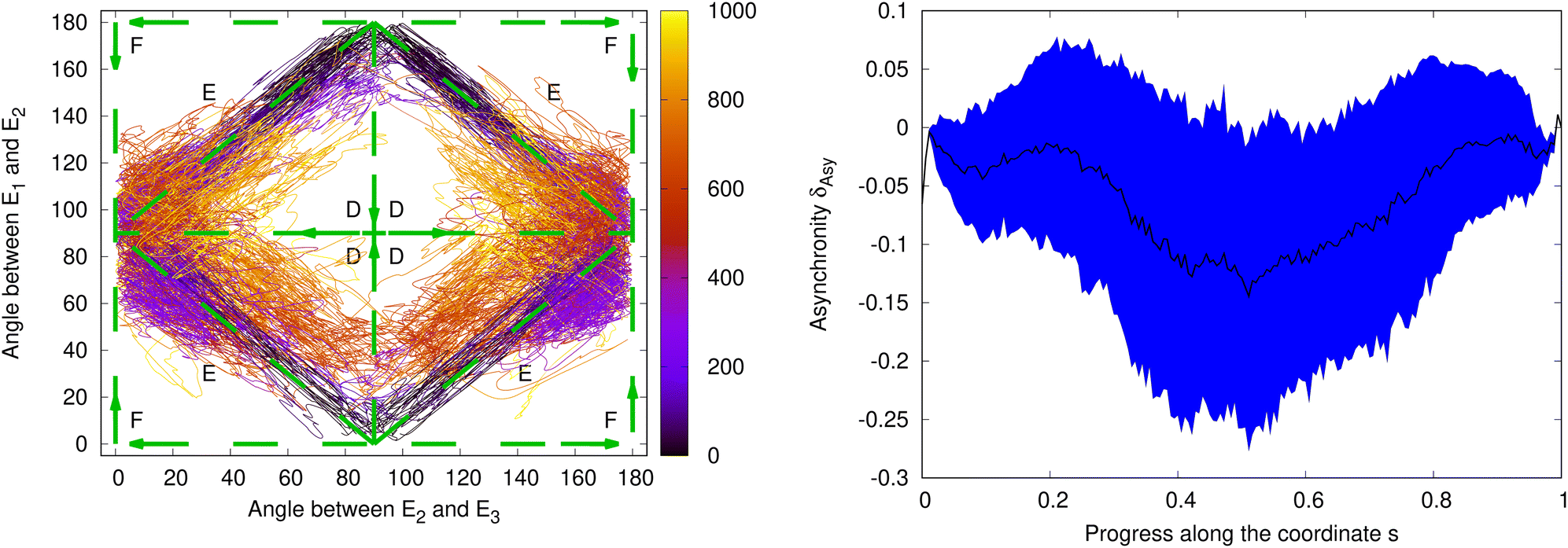
As pointed out in the introduction, different pathways are conceivable for the rotations on the S1 PES from the ground-state structure to the PLATICT minima and the backward rotations on the ground-state PES. One possibility could be along routes A and D (see Fig. 1) via a fully twisted structure (II*) at (90°,90°), i.e. in the excited state first a twist of τE2,E3 followed in a second step by a planarization of τE1,E2 and vice versa on S0. The routes C and F assume a fully planarized intermediate structure (III* and III), i.e. in the excited state the structure first planarizes along τE1,E2 before it twists along τE2,E3. A third possibility are the routes B and E where the torsion angles change synchronously from (0°,90°) to (90°,0°) or (90°,180°).
Fig. 11 depicts the time evolution of τE1,E2 and τE2,E3 after photoexcitation for the 55 successfully completed trajectories. The amino-phenyl angle τE2,E3 starts at ca. 0°; after 100 fs the first trajectories reach τE2,E3 = 70°; after 400 fs all trajectories reached and stay at around τE2,E3 = 90°. The indol-amino angle τE1,E2 starts at ≈90°. For the majority of trajectories τE1,E2 has after 300 fs values around 180° and then oscillates around the value for the excited-state minima S1-Min-a and S1-Min-b at (90°,180°). A minority fraction of the trajectories stays for the first 300 fs around (0°,90°) close to ground-state values for the torsion angles before they now and then rotate to τE1,E2 = 0°, where S1-Min-c and S1-Min-d are located.
 | ||
| Fig. 11 Left: Time evolution of the relaxation pathways after photoexcitation. Shown are the angle between the indol and the amino group, τE1,E2, on the y axes and the angle between the amino and the phenol group, τE2,E3, on the x axes. The time evolution (in fs) is indicated by the color. Indicated are the possible pathways over the planar (dashed, C), twisted (dashed, A) or synchron (dashed, B) structure (as in Fig. 1). Shown are the 55 trajectories that were successfully completed in an excited state. Right: Analysis of the asynchronicity of the indol-amino and amino-phenyl torsions for the relaxation after photoexcitation. Shown are mean value (black line) and the mean value plus/minus one standard deviation (blue shaded area) of δAsy for the 55 successfully completed trajectories that remained in an excited state along the coordinate s (see text). | ||
After 1000 fs, the end of the trajectories, τE1,E2 is planarized and τE2,E3 twisted, which corresponds to the PLATICT structures on the S1 PES. For the relaxation pathways in the excited states, we find a bifurcation with the majority of the trajectories relaxing to the minima S1-Min-a and S1-Min-b and a minority to S1-Min-c and S1-Min-d. To assign the trajectories to the different minima on the S1 PES, we started for each trajectory a geometry optimization on the S1 PES from the final structure reached at 1000 fs. After geometry optimization 15% ± 8% have been in S1-Min-a, 66% ± 10% in S1-Min-b, 8% ± 6% in S1-Min-c, and 11% ± 7% in S1-Min-d. As a limited number of trajectories has been used, the statistical analysis should only be considered qualitatively.
From Fig. 11 it is apparent that the two torsions in the excited state proceed close to straight lines that connect the ground-state structure at (0°,90°) with the S1 minima at (90°,0°) and (180°,0°) which corresponds to mostly synchronous pathways (B in Fig. 1). To investigate the degree and direction of asynchronicity in the changes of τE1,E2 and τE2,E3, we the define the asynchronicity measure δAsy which indicates the deviation from a synchronous pathway:

δ Asy = 1.0 corresponds a totally planar structure (III or III* in Fig. 1) and δAsy = −1.0 to a completely twisted structure (II or II*). In the representation used in Fig. 11, structures with a negative δAsy (preferentially twisted) are located in the center and structures with positive asynchronicity (preferentially planar) are located close to the outer corners.
In addition to the asynchronity we define an internal coordinate s to measure the relative position between the ground-state and the excited-state minima along the two torsion angles as:

A value of s = 1.0 corresponds to an excited state minima and s = 0.0 corresponds to a ground state minimum.
Fig. 11 depicts the average asynchronicity during the relaxation in the excited states from the Franck–Condon point to the PLATICT minima and its standard deviation. As the average asynchronity is close to 0, the motion is considered as almost synchronous. During the first third of the pathway the average asynchronity is positive: the trajectories are closer to a planar structure (structure III* in Fig. 1). For the rest of the pathway, the majority of trajectories are moving through structures with a negative asynchronicity, i.e. slightly closer to the TICT structures (II* in Fig. 1) than to the PLICT structure.
After having discussed the relaxation in the excited state after photoexcitation, we now turn the focus to the relaxation after emission on the ground-state PES. The results for the electronic and geometric relaxation in the excited state in Fig. 7 and 11 showed that the S1 state and also the regions of the S1 minima are reached quite fast. The time constant for the conversion from S3 and S2 to S1 is only ≈47 fs and after about 300–400 fs the PLATICT structure is reached. On the other hand, the simulated emission spectrum in Fig. 9 shows a small oscillator strength, meaning that the emission and deexcitation to the ground state is slow. Thus, in solution, the hop to the ground state should occur mostly after some of the kinetic excess energy has been dissipated to the environment. Therefore, we started the simulation of the dynamics for the relaxation after deexcitation to the ground state from Wigner distributions for the four excited state minima.
Fig. 12 shows the time evolution of the torsion angles τE1,E2 and τE2,E3 during the simulation of the relaxation on the ground-state PES after fluorescence for the selected 164 trajectories. The angle between the phenyl ring and the amino group, τE2,E3, starts at around 90° and reaches values around the ground-state minima of ≈0° or ≈180° after about 200 fs. (Note, that because of the symmetry of the phenyl ring the structures at 0° and 180° are symmetry-equivalent.) The angle between the amino and the indol group, τE1,E2, has values around 0° or 180° at the start of the trajectories. It reaches ≈90° after about 150 fs and then oscillates between ≈50° and ≈130° (around 90°) every 200–300 fs. The simulation shows that after emission the molecule returns to one of the ground-state minima in Fig. 2, i.e. τE1,E2 relaxes back to a twisted and τE2,E3 to a planar orientation. Apart from a 180° rotation of the phenyl ring, we observe a bifurcation of the pathways into groups relaxing either to S0-Min-1 or S0-Min-2 with final geometries around (0°,90°) and into their enantiomers with final geometries around (180°,90°).
 | ||
| Fig. 12 Left: Time evolution of the relaxation pathways on the ground-state PES after emission. Shown are the angle between the indol and the amino group, τE1,E1, on the y axes and the angle between the amino and the phenol group, τE2,E3, on the x axes. The time evolution (in fs) is indicated by the color. Initial conditions were taken from separate Wigner distributions for the four excited-state minima S1-Min-a, S1-Min-b, S1-Min-c and S1-Min-d. Indicated are the possible pathways over the planar (dashed, F), twisted (dashed, D) or synchron (dashed, E) structure (as in Fig. 1). Right: Analysis of the asynchronicity of the indol-amino and amino-phenyl torsions for the relaxation after photoemission. Shown are the mean value (black line) and the mean value plus/minus one standard deviation (blue shaded area) of δAsy for all successfully completed trajectories, weighted by the relative populations of the S1 minima found after the end of the excited state trajectories along the coordinate s (see text). | ||
To assign the structures assumed at the end of trajectories at 1000 fs to the different S0 minima, we started again for each of them from the final structure a geometry optimization. Dependending on the excited state minimum from which the trajectories were started from, we found different distributions of the end structures to the ground-state minima (for more information about the disentangled instead of the cummulative behavior of the ground state simulations see Table S2, ESI†). If the number of trajectories are weighted according to the ratio with which they are reached in the excited state dynamics, 28% ± 6% of the trajectories arrive in S0-Min-1 or its enantiomer and 72% ± 6% in S0-Min-2 or its enantiomer.
To analyze the asynchronicity between the rotations around the indol-amino and the amino-phenyl bonds, we determined again δAsy as function of the coordinate s. Fig. 12 depicts its mean value and its standard deviation that have been evaluated by weighting the ensembles generated for the four S1 minima by the respective populations found at the end of the excited-state dynamics.
Similar as during the excited-state dynamics, the two torsion angles change also for the relaxation after photoemission on the ground-state PES to a large extend but not fully synchronously. Over the whole pathway, the trajectories exhibit on average a small negative asynchronicity, i.e. a slight preference towards twisted intermediate structures. When analyzing the trajectories started from the different excited state minima separately, different trends are observed: for the first fifth of the pathway, the trajectories show on average negative asynchronicity, regardless of the minimum from which they have been started. Thereafter, the trajectories started from S1-Min-a have on average mostly a twisted character only showing a small planar character around s = 0.5. The trajectories started from S1-Min-b exhibit on average exclusively a twisted character. During the latter phase, the asynchronicity increases up to 20% of a fully twisted structure. Overall, the trajectories started from S1-Min-b show on average the largest asynchronicity. The trajectories started from S1-Min-c exhibit on average a twisted character, with a small planar character at around s = 0.2. The trajectories started from S1-Min-d oscillate between a planarized (on average up to 5% of the asynchronicity of a completely planarized structure) and a twisted asynchronicity (up to 5%). Across all time steps, the trajectories started from all minima have a preferentially twisted character (while S1-Min-d has the smallest asynchronity character).
3.5 Pathway of ground and excited state compared
As pointed out in the introduction, the pathways for the rotation around the indol-amino and the amino-phenyl bonds are important to assess the potential of N-aryl-substituted 1-aminoindoles for applications as molecular motors. For this, the full cycle of movements in the excited and in the ground state should form an unidirectional 360° rotation or there has to be at least a difference in the pathways for the forward and backward motions. Comparing Fig. 11 and 12, we can observe that the relaxation pathways in both the ground and the excited state run on average over intermediate structures with some degree of asynchronicity towards fully twisted structures. For the whole simulation pathway, this is more pronounced in the ground state.Integrating the asynchronicity over the pathways gives an idea about the effectiveness as motor. The difference of the integrals for the forward motion in the excited state and the backward motion on the ground state PES is a diagnostic that shows whether some mechanical work is done during a full cycle. The maximal mechanical work would be done along a hypothetical pathway which in the excited state would run through totally planarized structure and in the ground state through totally twisted structure or vice versa, i.e. a pathway with full asynchronicity (δAsy = ±1) in one direction in the excited state and the opposite asynchronicity in the ground state.
For IYABN we obtained for the trajectories on average a result from the Riemann summation that is 1% of the hypothetical maximum (with a standard deviation of 13%). Even if this number should be taken with caution, it indicates that although the pathways in the ground and excited states are very similar, they are not identical and that a small amount of kinetic work could be achieved during a full cycle.
4 Conclusions
The photophysical behaviour of IYABN after excitation with UV/VIS light has been investigated with static calculations as well as with surface hopping molecular dynamics simulations. The ground-state absorption spectrum has been computed by sampling vertical spectra calculated with ADC(2)/cc-pVDZ for a Wigner distribution for the ground-state equilibrium structures. Band shape and band position agree for the absorption within about 0.1 eV with the experimental absorption spectrum recorded in 1-chlorobutane once solvent and remaining basis set effects have been accounted for based on corrections from a single-point COSMO-ADC(2)/aug-cc-pVTZ calculation.The relaxation dynamics surface hopping simulations including the first 3 excited singlet states were carried out at the MP2/cc-pVDZ and ADC(2)/cc-pVDZ levels of theory, for the ground and the excited states, respectively. The results show that after the photoexcitation the system decays fast, with a time constant of about 47 fs to the lowest excited singlet state S1 and on the S1 PES within a few hundred fs to an intermolecular charge-transfer state with planarized amino-indol and twisted amino-phenyl torsion angles. No other minima in the excited state are reached during the relaxation. The time constant for the decay to the ground state found from the surface hopping dynamics is about 6.4 ps.
In the PLATICT state, one electron has been moved from the amino-indole donor group to the benzonitrile acceptor group. As a consequence, the oscillator strength for emission is very low. The simulated transient emission spectrum shows two bands: a bright band around 4 eV which appears immediately after excitation and decays rapidly with a time constant of 190 fs and a second, almost dark band at ≈2.4 eV which appears with the decay of the first band and persists until the end of the trajectories. The transition energy of the latter band is in good agreement with the experimental fluorescence spectrum recorded in 1-chlorobutane.20
The geometric analysis of the relaxation pathways after photoexcitation and after emission show that the rotations around the indol-amino and the amino-phenyl bonds happen both, in the excited state and on the ground state PES, almost synchronously. We observe only small asynchronicities of the rotations which are in the excited and in the ground state directed such that the pathways are on average a bit closer to fully twisted than to fully planarized intermediate structures. Comparison of the ground and excited state analysis reveals that the ground state dynamics occurs on average over more twisted structures than the relaxation in the excited states, depending on which of the energetically close-lying PLATICT minima is reached during relaxation in the excited state.
Because of the similarity of the relaxation pathways in the excited and the ground state, overall, only a small amount of mechanical work is done during a full relaxation cycle of IYABN. Still, the results indicate that the combination of PLICT and TICT chromophores to a PLATICT functionality can in principle be used to build molecular motors. The amount of accessible mechanical work per relaxation cycle can probably be increased by introducing higher structural asymmetry and sterical guidance by adding substituents with steric demands to achieve a higher degree of directionality for the relaxation pathways. Alternatively, the nitrile group can be changed or other substituents with electronic effects be introduced either in the phenyl or in the indole fragment of the N-aryl-1-aminoindole.
In this regard, it is already known from previous work20 that removing the nitrile group or replacing it by a carboxylic ester (MeOOC–) group, or a fluor atom can change the excited-state potential energy surfaces significantly.20 In computational studies of the fluoro and the unsubstituted counterparts of IYABN in vacuum not only a PLATICT but also a PLICT minimum was found. The PLATICT minima showed again large Stokes shifts of approx. 18000 cm−1 (for the unsubstituted N-(1H-indole-1-yl)aniline), and 16000 cm−1 (for the F-substituted counterpart N-(4-fluorophenyl)indol-1-amine), for the PLICT minima the Stokes shifts are only 11000 cm−1 (for the unsubstituted N-aryl-1-aminoindole) and 10000 cm−1 (for the F-substituted-N-aryl-1-aminoindole). Experimentally, only one fluorescence signal with a Stokes shift of 10000 cm−1 to 11000 cm−1 was found for both molecules in different solvents, which was assigned to a PLICT minimum. This shows that the potential energy surface for S1 can be altered such that the PLICT structure becomes a minimum on the S1 PES by changing the substituents. Our calculations have shown that for the CN-substituted derivative the PLICT structure is not a minimum and also not accessible as intermediate structure for the relaxation after photoexcitation. Tuning the S1 PES by substitution at the phenol and the indole subsystems such that the PLICT structure is low enough in energy to be accessible along the relaxation pathways, but not a stable minimum could open up relaxation pathways running over planarized structures in S1. If the planar structure on the S0 potential surface is not strongly stabilized by the same substitution so that the relaxation pathways for the backward motion on the S0 PES doesn't change in the same way, the difference in forward and backward motions could be significantly enlarged and more kinetic work could become accessible.
Conflicts of interest
The authors declare no conflict of interest.Data availability
The data that support the findings of this study are available on Zenodo at https://doi.org/10.5281/zenodo.15267389, reference number 15267389 and in the ESI.†Acknowledgements
Funded by the Deutsche Forschungsgemeinschaft (DFG, German Research Foundation) under Germany's Excellence Strategy–EXC 2033–390677874–RESOLV. We further acknowledge Vienna Scientific Cluster (VSC4 and VSC5) for allocation of computational resources and the University of Vienna for continuous support. We thank Prof. Gebhard Haberhauer for inspiring discussions and access to original data from ref. 20 for visualization.Notes and references
- S. Kassem, T. van Leeuwen, A. S. Lubbe, M. R. Wilson, B. L. Feringa and D. A. Leigh, Chem. Soc. Rev., 2017, 46, 2592–2621 RSC.
- R. Feynman, R. Leighton, M. Sands and E. Hafner, The Feynman Lectures on Physics, 1965; Vol. I, AAPT, 1965, vol. 33, p. 750 Search PubMed.
- K. Verhey, J. Dishinger and H. Kee, Biochem. Soc. Trans., 2011, 39, 1120–1125 CrossRef CAS PubMed.
- M. J. Lynch, R. Levenson, E. A. Kim, R. Sircar, D. F. Blair, F. W. Dahlquist and B. R. Crane, Structure, 2017, 25, 317–328 CrossRef CAS PubMed.
- C. Kallweit, G. Haberhauer and S. Woitschetzki, Chem. – Eur. J., 2014, 20, 6358–6365 CrossRef CAS PubMed.
- E. R. Kay, D. A. Leigh and F. Zerbetto, Angew. Chem., Int. Ed., 2007, 46, 72–191 CrossRef CAS PubMed.
- G. Haberhauer, Angew. Chem., Int. Ed., 2011, 50, 6415–6418 CrossRef CAS PubMed.
- C. García-Iriepa, M. Marazzi, F. Zapata, A. Valentini, D. Sampedro and L. M. Frutos, J. Phys. Chem. Lett., 2013, 4, 1389–1396 CrossRef PubMed.
- J. Wang and B. Durbeej, ChemistryOpen, 2018, 7, 583–589 CrossRef CAS PubMed.
- J. Wang, B. Oruganti and B. Durbeej, Org. Lett., 2020, 22, 7113–7117 CrossRef CAS PubMed.
- J. Michl and E. C. H. Sykes, ACS Nano, 2009, 3, 1042–1048 CrossRef CAS PubMed.
- D. T. Payne, J. Labuta, Z. Futera, V. Březina, L. Hanyková, M. K. Chahal and J. P. Hill, Org. Chem. Front., 2022, 9, 39–50 RSC.
- R. Eelkema, M. Pollard, J. Vicario, N. Katsonis, B. Serrano Ramon, C. Bastiaansen, D. Broer and B. Feringa, Nature, 2006, 440, 163 CrossRef CAS PubMed.
- S. Stolz, O. Gröning, J. Prinz, H. Brune and R. Widmer, Proc. Natl. Acad. Sci. U. S. A., 2020, 117, 14838–14842 CrossRef CAS PubMed.
- S. P. Fletcher, F. Dumur, M. M. Pollard and B. L. Feringa, Science, 2005, 310, 80–82 CrossRef CAS PubMed.
- F. Romeo-Gella, I. Corral and S. Faraji, J. Chem. Phys., 2021, 154, 064111 CrossRef CAS PubMed.
- N. Koumura, R. Zijlstra, R. van Delden, N. Harada and B. Feringa, Nature, 1999, 401, 152–155 CrossRef CAS PubMed.
- G. Pérez-Hernández and L. González, Phys. Chem. Chem. Phys., 2010, 12, 12279–12289 RSC.
- J. Wen, S. Mai and L. González, J. Phys. Chem. A, 2023, 127, 9520–9529 CrossRef CAS PubMed.
- G. Haberhauer, Chem. – Eur. J., 2017, 23, 9288–9296 CrossRef CAS PubMed.
- S. Sasaki, G. P. C. Drummen and G.-i Konishi, J. Mater. Chem. C, 2016, 4, 2731–2743 RSC.
- C. Wang, W. Chi, Q. Qiao, D. Tan, Z. Xu and X. Liu, Chem. Soc. Rev., 2021, 50, 12656–12678 RSC.
- G. Haberhauer, R. Gleiter and C. Burkhart, Chem. – Eur. J., 2016, 22, 971–978 CrossRef CAS PubMed.
- W. Rettig, Angew. Chem., Int. Ed. Engl., 1986, 25, 971–988 CrossRef.
- R. Misra and S. Bhattacharyya, Intramolecular Charge Transfer: Theory and Applications, Wiley-VCH Verlag GmbH Co. KGaA, London, 2018 Search PubMed.
- W. Rettig and B. Zietz, Chem. Phys. Lett., 2000, 317, 187–196 CrossRef CAS.
- A. Köhn and C. Hättig, J. Am. Chem. Soc., 2004, 126, 7399–7410 CrossRef PubMed.
- C. Zhong, Phys. Chem. Chem. Phys., 2015, 17, 9248–9257 RSC.
- W. Rettig, Angew. Chem., Int. Ed. Engl., 1986, 25, 971–988 CrossRef.
- Z. R. Grabowski, K. Rotkiewicz and W. Rettig, Chem. Rev., 2003, 103, 3899–4032 CrossRef PubMed.
- J. C. Tully, J. Chem. Phys., 1990, 93, 1061–1071 CrossRef CAS.
- M. Richter, P. Marquetand, J. González-Vázquez, I. Sola and L. González, J. Chem. Theory Comput., 2011, 7, 1253–1258 CrossRef CAS PubMed.
- S. Mai, P. Marquetand and L. González, Wiley Interdiscip. Rev.:Comput. Mol. Sci., 2018, 8, e1370 Search PubMed.
- S. Mai, D. Avagliano, M. Heindl, P. Marquetand, M. F. S. J. Menger, M. Oppel, F. Plasser, S. Polonius, M. Ruckenbauer, Y. Shu, D. G. Truhlar, L. Zhang, P. Zobel and L. González, SHARC3.0: Surface Hopping Including Arbitrary Couplings – Program Package for Non-Adiabatic Dynamics, 2023 DOI:10.5281/zenodo.7828641.
- A. B. Trofimov and J. Schirmer, J. Phys. B:At., Mol. Opt. Phys., 1995, 28, 2299 CrossRef CAS.
- A. Trofimov, I. Krivdina, J. Weller and J. Schirmer, Chem. Phys., 2006, 329, 1–10 CrossRef CAS.
- TURBOMOLE V7.7 2022, a development of University of Karlsruhe and Forschungszentrum Karlsruhe GmbH, 1989–2007, TURBOMOLE GmbH, since 2007; available from https://www.turbomole.org.
- S. G. Balasubramani, G. P. Chen, S. Coriani, M. Diedenhofen, M. S. Frank, Y. J. Franzke, F. Furche, R. Grotjahn, M. E. Harding, C. Hättig, A. Hellweg, B. Helmich-Paris, C. Holzer, U. Huniar, M. Kaupp, A. Marefat Khah, S. Karbalaei Khani, T. Müller, F. Mack, B. D. Nguyen, S. M. Parker, E. Perlt, D. Rappoport, K. Reiter, S. Roy, M. Rückert, G. Schmitz, M. Sierka, E. Tapavicza, D. P. Tew, C. van Wüllen, V. K. Voora, F. Weigend, A. Wodyski and J. M. Yu, J. Chem. Phys., 2020, 152, 184107 CrossRef CAS PubMed.
- M. Häser and R. Ahlrichs, J. Comput. Chem., 1989, 10, 104–111 CrossRef.
- C. Hättig and F. Weigend, J. Chem. Phys., 2000, 113, 5154–5161 CrossRef.
- C. Hättig, A. Hellweg and A. Köhn, Phys. Chem. Chem. Phys., 2006, 8, 1159–1169 RSC.
- C. Hättig and A. Köhn, J. Chem. Phys., 2002, 117, 6939–6951 CrossRef.
- C. Hättig, Adv. Quantum Chem., 2005, 50, 37–60 CrossRef.
- J. Schirmer, Phys. Rev. A, 1982, 26, 2395–2416 CrossRef CAS.
- F. Weigend, A. Köhn and C. Hättig, J. Chem. Phys., 2001, 116, 3175–3183 CrossRef.
- T. H. Dunning, J. Chem. Phys., 1989, 90, 1007–1023 CrossRef CAS.
- R. A. Kendall, T. H. Dunning and R. J. Harrison, J. Chem. Phys., 1992, 96, 6796–6806 CrossRef CAS.
- D. E. Woon and T. H. Dunning, J. Chem. Phys., 1994, 100, 2975–2988 CrossRef CAS.
- A. Klamt and G. Schüürmann, J. Chem. Soc., Perkin Trans. 2, 1993, 799–805 RSC.
- S. Karbalaei Khani, A. Marefat Khah and C. Hättig, Phys. Chem. Chem. Phys., 2018, 20, 16354–16363 RSC.
- A. A. Maryott, E. R. Smith, Table of Dielectric Constants of Pure Liquids, U. S. Govt. Print. Off., 1951, p. 13, https://apps.dtic.mil/dtic/tr/fulltext/u2/a278956.pdf Search PubMed.
- S. Budavari, The Merck index: an encyclopedia of chemicals, drugs, and biologicals, Merck, Rahway, N.J., U.S.A., 11th edn, 1989, p. 239 Search PubMed.
- R. Schinke, Photodissociation Dynamics: Spectroscopy and Fragmentation of Small Polyatomic Molecules, Cambridge University Press, 1993 Search PubMed.
- J. P. Dahl and M. Springborg, J. Chem. Phys., 1988, 88, 4535–4547 CrossRef CAS.
- S. Mai, P. Marquetand and L. González, Int. J. Quantum Chem., 2015, 115, 1215–1231 CrossRef CAS.
- D. Tuna, D. Lefrancois, Ł. Wolański, S. Gozem, I. Schapiro, T. Andruniów, A. Dreuw and M. Olivucci, J. Chem. Theory Comput., 2015, 11, 5758–5781 CrossRef CAS PubMed.
- F. Plasser, R. Crespo-Otero, M. Pederzoli, J. Pittner, H. Lischka and M. Barbatti, J. Chem. Theory Comput., 2014, 10, 1395–1405 CrossRef CAS PubMed.
- G. Granucci, M. Persico and A. Toniolo, J. Chem. Phys., 2001, 114, 10608–10615 CrossRef CAS.
- F. Plasser, M. Ruckenbauer, S. Mai, M. Oppel, P. Marquetand and L. González, J. Chem. Theory Comput., 2016, 12, 1207–1219 CrossRef CAS PubMed.
- S. Mai, F. Plasser, M. Pabst, F. Neese, A. Köhn and L. González, J. Chem. Phys., 2017, 147, 184109 CrossRef PubMed.
- G. Granucci, M. Persico and A. Zoccante, J. Chem. Phys., 2010, 133, 134111 CrossRef PubMed.
- M. Barbatti, G. Granucci, M. Persico, M. Ruckenbauer, M. Vazdar, M. Eckert-Maksić and H. Lischka, J. Photochem. Photobiol., A, 2007, 190, 228–240 CrossRef CAS.
- R. L. Martin, J. Chem. Phys., 2003, 118, 4775–4777 CrossRef CAS.
- O. Christiansen, H. Koch and P. Jørgensen, Chem. Phys. Lett., 1995, 243, 409–418 CrossRef CAS.
- S. Mai, F. Plasser, M. Pabst, F. Neese, A. Köhn and L. González, J. Chem. Phys., 2017, 147, 184109 CrossRef PubMed.
- F. Neese, Wiley Interdiscip. Rev.:Comput. Mol. Sci., 2012, 2, 73–78 CAS.
- S. Nangia, A. W. Jasper, T. F. Miller and D. G. Truhlar, J. Chem. Phys., 2004, 120, 3586–3597 CrossRef CAS PubMed.
- T. Williams, C. Kelleyet al.Gnuplot 5.2.8: an interactive plotting program, https://gnuplot.sourceforge.net/, 2019 Search PubMed.
- S. Mai, F. Plasser, J. Dorn, M. Fumanal, C. Daniel and L. González, Coord. Chem. Rev., 2018, 361, 74–97 CrossRef CAS.
- F. Plasser and H. Lischka, J. Chem. Theory Comput., 2012, 8, 2777–2789 CrossRef CAS PubMed.
- F. Plasser, J. Chem. Phys., 2020, 152, 084108 CrossRef CAS PubMed.
- D. Cremer and J. A. Pople, J. Am. Chem. Soc., 1975, 97, 1354–1358 CrossRef CAS.
Footnote |
| † Electronic supplementary information (ESI) available. See DOI: https://doi.org/10.1039/d5cp00889a |
| This journal is © the Owner Societies 2025 |