
 Open Access Article
 This Open Access Article is licensed under a
 Creative Commons Attribution 3.0 Unported Licence
Electronic structure of norbornadiene and quadricyclane†
Joseph C.
Cooper
 and
Adam
Kirrander
*
and
Adam
Kirrander
*
Physical and Theoretical Chemistry Laboratory, University of Oxford, South Parks Road, Oxford, OX1 3QZ, UK. E-mail: joseph.cooper@chem.ox.ac.uk; adam.kirrander@chem.ox.ac.uk
First published on 7th January 2025
Abstract
The ground and excited state electronic structure of the molecular photoswitches quadricyclane and norbornadiene is examined qualitatively and quantitatively. A new custom basis set is introduced, optimised for efficient yet accurate calculations. A number of advanced multi-configurational and multi-reference electronic structure methods are evaluated, identifying those sufficiently accurate and efficient to be used in on-the-fly simulations of photoexcited dynamics. The key valence states participating in the isomerisation reaction are investigated, specifically mapping the important S1/S0 conical intersection that governs the non-radiative decay of the excited system. The powerful yet simple three-state valence model introduced here provides a suitable base for future computational exploration of the photodynamics of the substituted molecules suitable for e.g. energy-storage applications.
1 Introduction
The isomers quadricyclane (QC) and norbornadiene (NBD) form a compact molecular photoswitch, capable of inter-converting upon photoabsorption via a [2+2] (retro-)cycloaddition reaction,1,2 as depicted in Fig. 1. QC stores an significant amount of energy (≈1 eV per molecule or ≈20 kcal mol−1), making it a candidate for high-energy density materials (HEDMs).3–5 The system has been the subject of intense theoretical6–15 and experimental15–20 scrutiny. It constitutes the central unit in molecular solar thermal (MOST) systems, capable of capture and storage of solar energy,3,9 and has been proposed for other applications that include information storage and optical devices.14,21–23 | ||
Fig. 1 Skeletal formulae of quadricyclane (QC, left) and norbornadiene (NBD, right), with the carbon atoms numbered. UV light absorption drives the reversible transformation between the two isomers. NBD has two doubly-bonded carbon atoms, C1![[double bond, length as m-dash]](https://www.rsc.org/images/entities/char_e001.gif) C4 and C2C3, referred to as ‘wings’. In QC, the wings come together, with electrons from the double bonds in NBD forming C1–C2 and C4–C3 single bonds, resulting in a strained four-membered ring. In both molecules, the C7 atom forms a bridge between the C5 and C6 atoms. C4 and C2C3, referred to as ‘wings’. In QC, the wings come together, with electrons from the double bonds in NBD forming C1–C2 and C4–C3 single bonds, resulting in a strained four-membered ring. In both molecules, the C7 atom forms a bridge between the C5 and C6 atoms. | ||
In applications, substituents are used to modify the basic QC/NBD system to maximise the absorption of incident solar light and to increase the quantum yield of interconversion between the isomers. This is often achieved by breaking the C2v symmetry, allowing stronger absorption into the reactive states, and using chromophoric groups conjugating into the NBD π-system.3 In the gas phase, especially at higher energies (≥6 eV), the Rydberg state manifold comes into play, complicating the isomerisation by introducing slower and less efficient decay channels.15,16 However, substitutions often lower the relative energy of the reactive valence states, separating the two manifolds. Moreover, in applications such as MOSTs, the issue is removed altogether since the Rydberg states are quenched in the condensed phase.24 The focus of the current work is thus on the valence electronic states that play a critical role in the decay and isomerisation dynamics.
The photochemistry of the QC/NBD system is of fundamental interest. As mentioned, the system provides an important example of a [2+2] (retro-)cycloaddition.1,2 Furthermore, it has a single characteristic conical intersection (CI), which governs the decay from the first excited to the ground electronic state. This same CI is accessed whether QC or NBD is excited, providing an opportunity to study how the approach of wavepackets to CIs affects their transmission. Understanding the photoexcited dynamics of the QC/NBD system and interpreting a growing number of time-resolved experiments requires simulations of the excited dynamics and the decay process. A necessary prerequisite for these is accurate, computationally feasible, and globally valid electronic structure models, which is one of the goals of the current study.
The electronic structure of the excited states in the QC/NBD system is challenging. Rydberg states notwithstanding, the system exhibits strong multi-configurational character with dramatic changes as the molecule distorts between the QC and the NBD isomers during the dynamics. Consequently, different electronic structure methods can predict quite different results, and many suffer significant stability issues. Benchmarking the predictions against experimental data is non-trivial, given that standard spectroscopy only reveals information about the bright states of the two isomers, and then only in the Franck–Condon regions. Therefore, it is essential to assess the electronic structure methods via secondary properties such as quantum-yields and, as here, by carefully comparing different electronic structure methods.
In previous theoretical work on QC/NBD, one focal area has been the assignment of vibronic transitions in the highly excited Rydberg and ionic manifolds above the ground-state geometries.18–20,25–27 One of the first studies to consider the role of the excited electronic states in the dynamics was carried out by Antol, who used an augmented CASSCF(4,4)+3s approach to predict how an excited 3s state may decay through a doubly and then a singly excited state to a conical intersection with the ground electronic state.11 Coppola et al. used CASSCF(4,7) and CASPT2 to highlight the role of the doubly-excited state in non-adiabatic transfer,12 in close accord with Antol. At about the same time, Hernandez et al. performed surface-hopping dynamics simulations (including on a substituted derivative),28 returning qualitative similar results to Antol and Coppola et al. Finally, Valentini et al. used CASSCF(4,8)-level theory to model coherent control experiments in QC/NBD.10 Previous work by the current authors simulated the dynamics in photoexcited QC using RMS-CASPT2(2,6) electronic structure and compared the results to time-resolved photoelectron spectroscopy experiments.15 All the previous treatments listed above include the Rydberg states, differing mostly in how and which additional Rydberg orbitals are included, and most employ active spaces closely related to the (4,4)-active space. There are also previous studies that consider more systematically the role of substitutions on the QC/NBD system, and how they affect the (excited state) potentials.6,9
Our main goal is to undertake a series of theoretical explorations of the QC/NBD system and to provide detailed benchmarks, first concentrating on the electronic structure of the unsubstituted molecule. The insights provided by systematically evaluating different electronic structure methods and basis sets allow us to make observations regarding static vs. dynamic correlation, the role of the doubly excited character in the wavefunction, assess the validity of the results away from the Franck–Condon region, and to discuss the different electronic structure methods considered. In doing so, we report extensive benchmarks using multi-configurational active space methods (CASSCF, CASPT2, and MRCI), selected configuration interaction (SHCI), and coupled cluster methods (LR-CC3 and LR-CCSD). These systematic comparisons allow us to identify electronic structure models suitable for dynamics simulations. Several recent publications have highlighted the importance of these models on non-adiabatic simulations,29–32 and the electronic structure models presented here can be exploited to investigate how subtle changes in the potential energy surfaces affect the photochemical dynamics.
2 Qualitative photochemistry
In this section, we discuss the general trends in the electronic structure of QC/NBD. These qualitative aspects manifest in all the electronic structure methods investigated here and provide general insights into the overall photochemical behaviour of this system. Notably, they constitute an essential background for analysing the efficacy of the various approaches to the electronic structure.Consider first the two isomers shown schematically in Fig. 1. NBD (right) has two double-bonded ‘wings’ formed by atoms C1C4 and C2C3, respectively. In QC (left), the wings move closer together as the molecule undergoes [2+2] retro-cycloaddition, whereby the double bonds break and cyclise to form the eponymous four-membered ring of QC. Given the central role played by the four carbons C1–C4, it is reasonable to start with a simple Hückel-like picture. The four symmetrised combinations of C(px)-orbitals are shown in Fig. 2, with the x-axis aligned with the C1–C2 and C3–C4 bonds in QC and the y-axis with the C1C4 and C2C3 bonds in NBD. The former bonds have predominantly σ-character, while the latter are π-character.
 | ||
| Fig. 2 Schematic of the four principal orbitals, with only carbons 1–4 and their px orbitals shown (cf.Fig. 1). In NBD, the B1 and B2 orbitals are the HOMO and LUMO, respectively, and vice versa in QC. Inter-nuclear nodes are drawn as dashed lines. All four orbitals constitute the (4,4) active space, while the dashed box denotes the (2,2) active space. Orbitals from electronic structure calculations are shown in Section S1 of the ESI.† | ||
Each orbital has a symmetry label, which we refer to throughout the text, sometimes combined with a pithy label that indicates the π-bonding character for the wings (along y) and the σ-bonding character between the wings (along x). For example, in the B1(πσ*) orbital the label in parenthesis signifies that the orbital has bonding character along the C1–C4 and C2–C3 π-bonds, but anti-bonding character for the C1–C2 and C3–C4 σ-bonds. As each carbon contributes one electron to these orbitals, we have four electrons in these orbitals. The corresponding configuration state functions (CSFs) in this subsystem are labelled as |ηA1ηB1ηB2ηA2〉, where η denotes the occupation for each specified orbital, either 0, 1 (u for up and d for down spin), or 2.
We consider three states: the ground S0 (1A1) state, the first excited S1 (1A2) valence state, and the second, doubly excited S2 (2A1) valence state. The S1 (1A2) state is the simplest, with |2ud0〉 the leading configuration at both QC and NBD geometries. The two A1 states, S0 and S2, are more complicated. In NBD, S0 has |2200〉 character while S2 has |2020〉. In QC, this is reversed, with the ground state having |2020〉 character and S2 |2200〉. The correlation between states is shown pictorially in Fig. 3. Thus, the origin of the MOST and photoswitch nature of this system is apparent: the ground state isomerisation involves a change in character of the wavefunction, resulting in a large barrier, while the excited states couple to the other isomer's ground state, leading to efficient excited-state isomerisation. The reaction of the molecules can therefore be rationalised using the orbital characters in Fig. 2, and it is clear exciting either the S1 or S2 state from the NBD minimum will cause motion towards the QC minimum, or vice versa.
 | ||
| Fig. 3 State correlation diagram for the QC/NBD system, with energy increasing up the diagram. Figure drawn to scale for SA(3)-CASSCF(2,2)/p-cc-(p)VDZ energies. | ||
For non-radiative decay, the S1/S0 conical intersection (CI) plays a crucial role. The minimum energy conical intersection (MECI) geometry is included in Fig. 4. The S1 state has A2 symmetry and thus the MECI distorts to C2 symmetry, with a distinctive rhombic arrangement of atom C1–C4. This distortion is akin to other [2+2] systems, such as the well-studied ethylene dimerisation.2,33,34 The C2 symmetry indicates that left- and right-handed CI variants exist—we shall not distinguish them. At the S1/S0 conical intersection, the wavefunction is exceptionally multi-configurational, with all three of the |2020〉, |2ud0〉 and |2200〉 configurations strongly occupied in the S0 and S1 states.
 | ||
| Fig. 4 Representative optimised molecular geometries. The QC ground state (top left) has the characteristic four-membered ring, whereas the NBD (top right) has two separate double-bonded ‘wings’. The S1/S0 MECI (bottom left) has a distinct rhombic arrangement of the four-carbon moiety, while the S1 minimum (bottom right), which appears in some of the calculations, is quite similar to the NBD ground state, with slightly closer wings. The optimised geometries shown are obtained using SA(3)-CASSCF(2,2)/p-cc-(p)VDZ. | ||
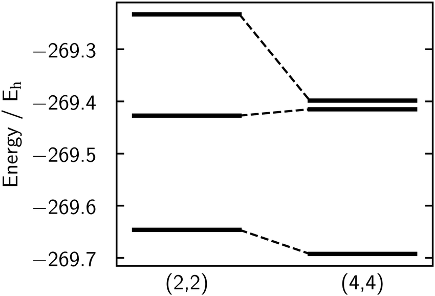 | ||
| Fig. 5 Absolute energies for the three states S0, S1, and S2 at NBD equilibrium geometry for the (2,2) (left) and (4,4) (right) active spaces, calculated at the SA(3)-CASSCF/p-cc-(p)VDZ level. Note that although the state-averaged energy is lower for the (4,4) calculation, the S1 state energy is higher for the (4,4) active space compared to the (2,2). | ||
During dynamics, the molecule will break the C2v symmetry, and so we shall drop the state symmetry labels and use only the adiabatic Sn labelling scheme, punctuated with a leading character label to keep track of the state character (see also Fig. S25 in ESI†). Finally, we stress that the model introduced here does not include the Rydberg or other valence states that appear between the singly- and doubly-excited valence states in the gas phase. The current adiabatic labels Sn are thus only valid in the context of this model. A complete analysis of the spectra of these molecules in the gas phase is given in our previous work,27 and more details on why this approximation is valid are given in Section S6 of the ESI.†
3 Computational methods
3.1 Electronic structure calculations
Electronic structure calculations are performed using OpenMolcas v23.0235 (CASSCF, XMS-CASPT2), COLUMBUS 7.636 (CASSCF, MRCI) and eT 1.937 (LR-CC). For CASSCF calculations, the results from OpenMolcas and COLUMBUS are effectively identical. The XMS-CASPT2 calculations are performed with a level-shift of 0.2i, the minimum value required to remove all intruder states. The potential energies are relatively sensitive to this shift (see Fig. S20, ESI†). The MRCI calculations are performed using COLUMBUS with the uncontracted formalism, and the XMS-CASPT2 use the single-state single-reference formulation in OpenMolcas. Analysis shows the different formalisms in XMS-CASPT2 and MRCI affect the (4,4) active space but not (2,2) active space (see Fig. S15, ESI†). Cholesky decomposition35,37 (CD) is used when possible, and the inclusion of this does not significantly change the results. All correlated methods (MRCI, CASPT2, LR-CC) use frozen carbon 1s orbitals.The electronic structure calculations are not overly sensitive to the basis, provided the basis set is sufficiently diffuse. In view of future non-adiabatic dynamics simulations, which require a large number of electronic structure evaluations, we have developed a custom adapted basis that is both efficient and accurate for this specific system. The basis is an altered version of cc-pVDZ,38 denoted p-cc-(p)VDZ. We remove the polarisation functions from the hydrogens, giving a [4s|2s] contraction equivalent in size to def2-SV(P) or 6-31G*, and add only the additional p diffuse functions from the aug-cc-pVDZ basis39 to the carbons, resulting in a [9s5p1d|3s3p1d] contraction. Discussion and evaluation of this basis, including the full contraction, is given in Section 4.3, with further benchmarking provided in Section S10 of the ESI.† Finally, a summary of the individual methods used in this work is presented in Table S6 in Section S12 of the ESI.†
3.2 Interpolations of internal coordinates
To compare the different electronic structure methods, we calculate the energies along linear interpolations in internal coordinates (LIICs), which provide effective one-dimensional ‘reaction coordinates’. We use two different sets of LIICs. The first, which is similar to that used in Borne et al.,15 connects the QC ground state equilibrium geometry to the S1/S0 MECI, and then proceeds to the NBD ground state equilibrium. We note that the combined LIIC involves a change in direction at the S1/S0 MECI. The second LIIC proceeds from the NBD ground state to the S1 minimum, only present in some of the calculations, and then to the S1/S0 MECI. This approximates the path for dynamics that proceeds via the S1 minimum. This second LIIC does not include the final path from the MECI towards QC, since this is already included in the first LIIC. The first LIIC (QC → S1/S0 → NBD), used in Fig. 6–8, is defined based on molecular geometries optimised using CASSCF(2,2)/p-cc-(p)VDZ for CASSCF calculations, while the LIIC is based on MRCI(2,2)/p-cc-(p)VDZ optimised geometries when comparing all other electronic structure methods. The second LIIC (S1/S0 → S1-min → NBD), used in Fig. 10, exists in one version only, obtained using CASSCF(2,2)/p-cc-(p)VDZ geometries. For reference, the CASSCF(2,2)/p-cc-(p)VDZ optimised geometries are shown in Fig. 4. As an aside, we note that all internal coordinates in the molecule change across each LIIC. | ||
| Fig. 6 Energies for S0, S1, and S2 calculated using SA(3)-CASSCF(2,2) (solid indigo lines), SA(3)-CASSCF(4,4) (dashed rose lines), and MRCI+Q(4,4) (dotted green lines) with the p-cc-(p)VDZ basis set. The (4,4) active space fails to converge around QC and is thus not shown in that region. CASSCF(2,2) and MRCI+Q(4,4) agree on the shape of the potential but not on the excitation energy at the NBD ground state equilibrium. Details of the LIIC pathway are given in Section 3.2. | ||
 | ||
| Fig. 7 Energies for S0, S1, and S2 calculated using XMS-CASPT2(2,2) (solid, purple), XMS-CASPT2(4,4) (rose, dashed), and LR-CC3 (green, dotted) with the p-cc-(p)VDZ basis set. All three methods agree well and also with MRCI+Q(4,4) shown in Fig. 6. XMS-CASPT2(4,4) shows a notably lower and different shape potential around the NBD geometry. Details of the LIIC pathway are given in Section 3.2. | ||
 | ||
| Fig. 8 Basis set comparison of p-cc-(p)VDZ (solid purple), cc-pVDZ (dashed rose), and ANO-L-VTQZ (dotted green), using the SA(3)-CASSCF(2,2) method. The S0, S1, and S2 energies agree very well for p-cc-(p)VDZ and ANO-L-VTQZ, which both have sufficiently diffuse character, while cc-pVDZ shows a significant increase in energy for the S1 and S2 excited states. Details of the LIIC pathway are given in Section 3.2. | ||
Finally, in Fig. 9 and 11, we show two-dimensional potential energy surfaces. These are calculated by using linear interpolations in Cartesian coordinates. Fig. 9 shows potential energy in the plane that contains the NBD and QC minima and the S1/S0 MECI, and Fig. 11 in the plane containing the NBD and S1 minima and the S1/S0 MECI.
 | ||
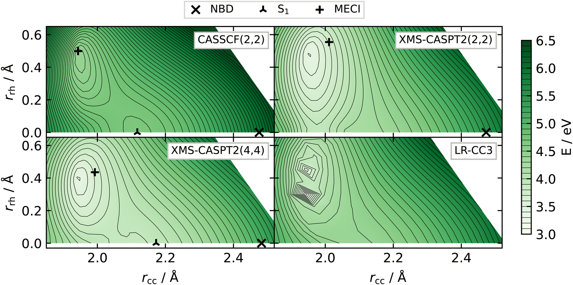
| Fig. 9 Potential energy surfaces in the plane defined by the NBD and QC minima and the S1/S0 MECI, calculated at the CASSCF(2,2)/p-cc-(p)VDZ level. The surfaces are plotted as a function of rcc and rrh (see eqn (1) and (2)). The S0 surface (rose) has two clear minima corresponding to the equilibrium geometries of QC ((rcc, rrh) ≈ (1.5, 0) Å) and NBD ((rcc, rrh) ≈ (2.5, 0) Å), separated by a large barrier. The S1 surface (yellow) connects with the S0 surface at the rhombic conical intersection on top of this barrier, indicated by the arrow. The S2 surface (light blue) interacts most strongly at rcc ≈ 2.0 Å, halfway between the two minima. Molecular structures from Fig. 4 are included for reference. | ||
4 Results
4.1 Static correlation
The multi-configurational and doubly-excited character of the NBD/QC system means that single-reference methods, such as ADC(2) and TDDFT, often give poor results, especially around the critical S1/S0 CI. The exception to this are high-order coupled cluster calculations, which are discussed later, but these are too expensive for dynamics in a system of this size. As such, we focus mainly on multi-configurational methods.From the qualitative discussion in Section 2, it is clear that a global representation of the electronic states requires that the active space includes the |2200〉, |2020〉, and |2ud0〉 configurations, which make leading contributions to the three states. A standard approach would be to utilise the complete set of the four orbitals and electrons as detailed in Fig. 2, i.e. a CASSCF(4,4) approach. Almost all previous work on the excited states of these molecules used methods based on this active space, generally including Rydberg states.10,11,28 We show how the addition of Rydberg states affects these potentials in Section S6 of the ESI.†
Alternatively, one could remove the A1 and A2 orbitals; these orbitals are fully occupied or unoccupied in the important configurations. This leads to a CASSCF(2,2) approach, which has particular computational advantage as state-averaging over three states leads to both orbitals always having a state-averaged occupation number of 1, leading to stable convergence.
This additional stability is evident in practice. The (4,4) active space has trouble converging to the same active space in QC-like geometries due to the formation of the σ-bond; the A1 orbital, with σ-bonding character, drops significantly in energy, while the A2 orbital, with σ*-anti-bonding character, rises significantly, leading to those orbitals being replaced in the optimisation. A third choice is a (4,3) active space, which gives similar results to the (2,2) active space but exhibits similar instabilities as the (4,4) active space (see Section S13 of ESI†). We finally note that we have already described all of the orbitals of the forming/breaking bonds, and thus the majority of the static correlation is recovered in these smaller active spaces. Larger active spaces therefore do not add more static correlation, and are unstable across the nuclear configuration space of the system.
We find that the (2,2) active space provides a better qualitative description of the potential energy surfaces, with the (4,4) active space biased against the S1 |2ud0〉 state. This is seen in Fig. 5, which shows the absolute energies for the (2,2) and (4,4) active spaces at the NBD geometry. The critical S1 |2ud0〉 state has a higher absolute energy in the larger (4,4) active space than the (2,2), While this may seem counter-intuitive, as the (4,4) state has more parameters and hence should give a lower variational energy, this only applies to the optimised state-averaged energy rather than the energy of individual states.
The poor description of S1 in CASSCF(4,4) can be rationalised using orbital occupations. The two A1 states contain four orbitals with occupations significantly different from 2 or 0, indicating that all four orbitals contribute to the correlation. The A2 state, on the other hand, only has the central two orbitals B1(πσ*) and B2(π*σ) with occupations not close to 2 or 0, and requires its correlation to come from excitations to the virtual space. CASSCF(4,4), therefore, describes the two A1 states better than the A2 state, leading to qualitatively incorrect energy gaps, while CASSCF(2,2) gives a more balanced description of the individual states. This pattern is seen in other molecules with two π-bonds, such as cyclopentadiene40 and 1,3-cyclohexadiene,41 where the doubly-excited state is lower in energy than the singly-excited state in CASSCF. Only by including more correlation, in those cases via XMS-CASPT2, does one retrieve the correct state ordering.
Here, we note that the CASSCF(2,2) does not describe the S2 state well in either NBD or QC. Specifically in the region around the NBD ground state equilibrium, the CASSCF(2,2) method does not include the |uudd〉, |2002〉, and |0220〉 configurations, which all contribute ≈10% to the doubly excited state. This leads to a significant increase in energy of the S2 state for CASSCF(2,2), as seen in Table 1. Fortunately, both the S1 and S0 states are well described, even in regions with significant doubly excited character. Additionally, we do not expect S2 to be populated to any notable degree during photoexcited dynamics (see the discussion below and in Section S5 of the ESI†), so the poor description should not affect simulations.
| Geometry | r cc/Å | r rh/Å | r db/Å | S1/eV | S2/eV | S0 | S1 | S2 |
|---|---|---|---|---|---|---|---|---|
| QC | 1.55 | 0 | 1.53 | 6.22 (5.75) | 14.02 (11.59) | |2020〉 | |2ud0〉 | |2200〉 |
| NBD | 2.47 | 0 | 1.33 | 5.96 (5.34) | 11.24 (7.85) | |2200〉 | |2ud0〉 | |2020〉 |
| S1/S0 MECI | 1.94 | ±0.50 | 1.44 | 0 (0.20) | 3.36 (3.11) | Mix | Mix | Mix |
| S1 min | 2.12 | 0 | 1.41 | 2.85 (2.85) | 4.56 (3.29) | |2200〉 | |2ud0〉 | |2020〉 |
The analysis so far only concerns the NBD geometry. A better overview is gained by making the comparison using potential energy cuts (PECs) along the LIICs introduced earlier (see Methods for details). All calculations use the optimised p-cc-(p)VDZ basis, with the results shown in Fig. 6.
The indigo solid lines are the relative energies for the three states in the SA(3)-CASSCF(2,2) calculation. We start on the right of the diagram, corresponding to NBD. The ground state, which has primary |2200〉 character, begins to rise as we move towards the centre of the plot, the S1/S0 MECI. Correspondingly, the S1 state, with primary |2ud0〉 character, comes down in energy to meet the ground state at the MECI. In the CI region, in the middle of the plot, these two states are of mixed character, containing strong contributions from the |2200〉, |2ud0〉 and |2020〉 configurations. The S2 state starts at much higher energy but then descends, mixing with the other two states. We note that in CASSCF(2,2), the doubly excited state is not well described, as mentioned earlier, but the two dynamically important states—S0 and S1—are well described across the LIIC. Finally, as we continue left in the plot, towards QC, the lowest two states separate again. The ground state, now with primary |2020〉 character, comes down to a value approximately 1 eV above the NBD ground state minimum, in line with previous work.3,12,28,42–46 All electronic structure methods considered in the present study recover this ground state energy gap acceptably. This difference between QC and NBD ground state energies is exploited for energy storage in MOST systems.3,6 Correspondingly, the S1 state again acquires primary |2ud0〉 character, and the S2 state rises very high in energy, where it is of primary |2200〉 character.
The rose dashed lines in the same plot show the relative energies for SA(3)-CASSCF(4,4). At the NBD equilibrium geometry, the S0 obtained by (4,4) is quite similar to (2,2), but as observed above, the S1 |2ud0〉 state appears at around 7.5 eV, far higher than the experimental value of 5.25 eV.19,25–27,47–51 In terms of dynamics, this would have a severe impact, both due to the energy shift and changes in gradients. Additionally, this pushes it closer to the S2 |2020〉 state, leading to their interaction region appearing closer to the NBD geometry. Moving towards the MECI, the two states do not quite meet, an artefact of using the CASSCF(2,2) geometries for the LIIC. When the states separate as we move to QC, we can see a notably steeper S1 state, again reflecting the poor description of the |2ud0〉 state. As mentioned earlier, the active space is unstable in QC, so we do not show the energies.
In summary, the CASSCF(2,2) calculations, while exceptionally simple, give a balanced description of the potential energy surfaces. On the other hand, the CASSCF(4,4) calculations specifically bias against the S1 |2ud0〉 state, increasing its energy. This is further confirmed in the next section, where we add dynamical correlation.
4.2 Dynamic correlation
Methods beyond CASSCF are required to recover the dynamical correlation. To evaluate the methods, we use a very similar LIIC, except calculated with a correlated method (MRCI(2,2)/p-cc-(p)VDZ, see Section 3.2). We now discuss MRCI, XMS-CASPT2, and finally methods that do not define an active space, such as linear response theories.For the (2,2) active space, the MRCI reference weights for all three roots are approximately the same, indicating that the quality of all three states in the original CASSCF calculation is similar. Indeed, the CASSCF(2,2) calculations show nice overall agreement with the MRCI+Q(2,2) calculations, as shown in Fig. S13 in the ESI.† The highest S2 state comes down in energy in the MRCI compared to CASSCF(2,2), but in dynamics at reasonably low energies, say <8 eV, this state is not expected to be populated.
For the (4,4) active space, it is crucial to include the Davidson correction (see Section S7 of the ESI†). Interestingly, MRCI+Q(4,4) gives a similar potential energy surface to CASSCF(2,2), as shown in Fig. 6 (green dotted lines). Notably, the two states are relatively parallel on the right-hand side of the pathway, only beginning to diverge around the conical intersection. The lack of agreement between the CASSCF(4,4) and MRCI+Q(4,4) calculations reflects the comments about the S1 |2ud0〉 state above; the reference weight of this state is much lower than the other two states, confirming its poor description in the CASSCF picture.
Overall, the MRCI+Q calculations give excellent quality potential energy surfaces, but the computational expense means that they are not suitable for on-the-fly dynamics. This is especially true since the Davidson correction only corrects the energy and not the underlying wavefunction, meaning that it is not possible to calculate analytical gradients and couplings.
At first glance, the XMS-CASPT2 calculations with the (2,2) active space, shown as the solid purple lines in Fig. 7, agree well with the MRCI+Q(4,4) calculations (Fig. 6) across all states. This agreement can be seen further in the excitation energies (shown in Section S3 of the ESI†). Furthermore, XMS-CASPT2(4,4) calculations, also included in Fig. 7, agree well with both these methods, with only minor differences in the excitation energy of S1. The conclusion, so far, is that MRCI+Q(4,4) produces credible reference potential energy surfaces but is not suitable for on-the-fly dynamics. The three methods that are feasible for dynamics, namely CASSCF(2,2), XMS-CASPT2(2,2) and (4,4), all agree on the overall topography of the potential energy surfaces. In the next section, we turn to non-active space methods as a final arbiter.
4.3 Basis sets
As mentioned earlier, the electronic structure calculations in QC/NBD are relatively insensitive to the choice of basis. However, accurate energies require that the basis is sufficiently diffuse. This is particularly notable for the S1 |2ud0〉 state, which has a marked diffuse character due to strong mixing with the 3px Rydberg state near the QC equilibrium geometry.15,27 To demonstrate, we compare SA(3)-CASSCF(2,2) energies using the p-cc-(p)VDZ (see Section 3.1) and cc-pVDZ basis sets in Fig. 8. The p-cc-(p)VDZ basis, which lacks hydrogen polarisation functions but adds diffuse p functions, shows a significantly lower excitation energy for the valence state than cc-pVDZ, especially near the QC ground state equilibrium geometry. The large ANO-L-VTQZ basis agrees well with the p-cc-(p)VDZ, justifying the new contraction. Further discussion of basis sets, including diffuseness, can be found in Section S10 of the ESI.†The p-cc-(p)VDZ basis uses only 135 spherical functions, reducing compute time for a single-point SA(3)-CASSCF(2,2) by two orders of magnitude compared to the ANO-L-VQZP basis. This computational efficiency is crucial for non-adiabatic dynamics simulations, which involve many repeated evaluations of the electronic structure. Finally, we note that if the Rydberg states are to be accounted for in the calculations, even more specifically adapted diffuse basis sets are required.15
5 Discussion
5.1 Critical points on the potential energy surface
Purely for the sake of visualisation, we define three coordinates, all involving carbon atoms C1–C4, as | (1) |
 | (2) |
 | (3) |
Fig. 9 shows the potential energy surfaces for the three important states in the plane defined by the QC and NBD minima and the S1/S0 MECI. The barrier between the two ground state minima is immediately apparent, with two distinct wells on the ground state surface corresponding to QC and NBD. The conical intersection linking to the ground state appears on top of this barrier, which explains the photoswitch nature of the system—depending on the path through the intersection, a wavepacket can end up in either potential well. Finally, the S2 state sits well above the S1 state at the geometries shown in Fig. 9, with a trough mirroring the potential barrier on the ground state. The change of character in the ground state wavefunction is evident, with strong coupling between the |2020〉 and |2200〉 configurations.
The NBD, QC, and S1/S0 MECI geometries remain relatively consistent across the different electronic structure methods (see e.g.Table 2 later and Table S1 in ESI†). However, in some methods, an additional S1 minimum with C2v symmetry and 1A2 |2ud0〉 character is found. This local minimum appears at higher energies than the S1/S0 MECI, with the molecular geometry approximately halfway between QC and NBD ground-state geometries (rcc ≈ 2.1 Å, rdb ≈ 1.4 Å). Notably, the plane shown in Fig. 9 does not contain the S1 local minimum. In the electronic structure methods where this minimum does not appear, a first-order symmetric saddle-point separates the left- and right-handed variants of the S1/S0 CI.
| Method | (m,n) | P | B | r cc | r db | r rh |
|---|---|---|---|---|---|---|
| CASSCF | (2,2) | 0.79 | 0.86 | 1.94 | 1.44 | ±0.50 |
| (4,4) | 0.82 | 1.82 | 2.03 | 1.51 | ±0.75 | |
| MRCI | (2,2) | 0.58 | 0.83 | 1.96 | 1.45 | ±0.49 |
| (4,4) | 0.78 | 1.11 | 1.99 | 1.48 | ±0.62 | |
| XMS-CASPT2 | (2,2) | 0.56 | 1.17 | 2.01 | 1.49 | ±0.56 |
| (4,4) | 0.30 | 0.83 | 1.99 | 1.49 | ±0.44 |
Since the S1 minimum appears relatively close to the Franck–Condon region of NBD, see Fig. 4, we anticipate it may significantly affect the dynamics. A deep minimum imprints a valley, attracting most of the initially excited wave packet before allowing it to proceed to the CI. Without this minimum, the potential is ridged and the wavepacket will evolve directly towards the CI. Interestingly, at the geometry of the local minimum, the S0 and S1 states have differing (A1 and A2, respectively), and thus do not interact. When displacing towards the S1/S0 CI (an A2 distortion), both states change to the A irreducible representation, leading to coupling and mixed |2ud0〉 and |2020〉 character in both states.
The vertical excitation energies and the leading configurations at these four molecular geometries are given in Table 1. As discussed earlier, the ground state wavefunctions for NBD and QC have different leading configurations, whereas the S1 state always maintains the |2ud0〉 configuration. At the MECI geometry, the S0 and S1 states are degenerate, and the second excited state is much lower in energy than in the NBD and QC geometries. The electronic states are thus strongly multi-configurational, with all three states having significant contributions of the |2200〉, |2020〉 and |2ud0〉 configurations.
Further, a S2/S1 CI appears when dynamical correlation is included. This CI epitomises the aforementioned mixing of the |2020〉 character into the S1 state, but, as it is a peaked CI being approached from the lower S1 surface, we do not expect the S2 state to significantly affect the dynamics.65 Further discussion is presented in Section S5 of the ESI.†
5.2 Nature of the potential energy surfaces
In the following, we discuss two key points on the potential energy surfaces. The first is the S1 minimum, which only appears when using a subset of the electronic structure methods, and the second is the S1/S0 conical intersection, which governs decay onto the ground electronic state. While all electronic structure methods evaluated provide reasonably similar descriptions of the conical intersection, even subtle differences in the topography of the potential energy surfaces in the vicinity of a conical intersection can have consequences for the photoexcited dynamics. For simulations, it is thus crucial to describe this region as accurately as possible.To explore this region of configuration space, we construct a different LIIC pathway, first going from the NBD ground state geometry to this local S1 minimum and then onwards to the S1/S0 MECI geometry.
The potential energy cuts for the previously shown methods are shown on this pathway in Fig. 10. The key feature in this pathway is a barrier between the S1 minimum and S1/S0 MECI, which must be present for an excited state minimum. Clearly, CASSCF(2,2), XMS-CASPT2(4,4) and LR-CC3 all show a small barrier, while CASSCF(4,4) and XMS-CASPT2(2,2) do not. The apparent barrier in MRCI+Q(4,4) is most likely an artefact of the optimisation procedure. CASSCF(4,4) stands out as clearly divergent, with a crossing of S2 and S1, showing that it lacks even the correct qualitative description. CASSCF(2,2), on the other hand, is at least qualitatively correct, although the conical intersection is higher than the other methods. LR-CC3 and XMS-CASPT2(4,4) agree closely on the shape of the potentials, with only a small energy offset—we would expect almost identical dynamics from these methods. Finally, we note that XMS-CASPT2(2,2) S2/S1 crossing occurs just off the pathway shown here, but we can see that the S2 state is notably closer in energy at the S1 minimum than in other methods, indicating much stronger influence.
 | ||
| Fig. 10 Energies for S0, S1, and S2 calculated along the LIIC pathway from the S1/S0 MECI to the S1 minimum, and finally to the NBD equilibrium geometry (see Section 3.2 for details). All calculations employ the p-cc-(p)VDZ basis. Left: CASSCF(2,2) (purple solid), CASSCF(4,4) (rose dashed), and MRCI+Q(4,4) (green dotted). The CASSCF(4,4) is again qualitatively incorrect, whereas CASSCF(2,2) shows a qualitatively correct shape, including a barrier between the S1 minimum and the S1/S0 MECI. The MRCI+Q(4,4) shows a small artefact around the S1 minimum due to the Davidson correction and the two excited states mixing. Right: XMS-CASPT2 [(2,2) solid purple, (4,4) rose dashed] and LR-CC3 (dashed green). All three methods look very similar, but the XMS-CASPT2(2,2) shows no barrier between the S1 minimum and S1/S0 MECI, while the other two only have a very small one. | ||
To highlight these effects, in Fig. 11 we show the S1 potential energy surface in the plane defined by the NBD and S1 minima and the S1/S0 MECI. For CASSCF(2,2) (top left), XMS-CASPT2(4,4) (bottom left) and LR-CC3 (bottom right), the overall shape of the potential energy is consistent, with a notable slope towards the S1 minimum (at (rcc, rrh) ≈ (2.1, 0) Å). We can clearly see the S1 minimum, with a characteristic ‘pinching’ of the contour lines around a saddle-point between the minimum and the conical intersection. XMS-CASPT2(2,2) (Fig. 11, top right) shows an entirely different shape, with a gradient pushing away from the would-be minimum and no obvious saddle-point. This is due to the crossing of the |2ud0〉 and |2020〉 states, leading to the S2/S1 conical intersection (see further discussion in Section S5 of the ESI†).
 | ||
| Fig. 11 S1 potential energies in the Cartesian plane defined by the NBD and S1 minima and the S1/S0 MECI geometries, calculated at CASSCF(2,2)/p-cc-(p)VDZ level. Energies calculated with CASSCF(2,2) (top left), XMS-CASPT2(2,2) (top right), XMS-CASPT2(4,4) (bottom left), and LR-CC3 (bottom right). Locations of optimised geometries (if they exist) are shown for the active space methods—we note that, for XMS-CASPT2, these are not the minimum geometries in this plane, as it is calculated using the structures at CASSCF(2,2) level. All but the XMS-CASPT2(2,2) have a similar overall shape, with a notable gradient towards the S1 minimum. LR-CC3 shows instability around the conical intersection but is smooth elsewhere. | ||
In summary, with both XMS-CASPT2(4,4) and LR-CC3 all showing an S1 minimum, we believe the evidence leans towards the presence of a bound local minimum on the excited state, as predicted by CASSCF(2,2).
 | ||
| Fig. 12 Branching plane X and Y vectors from S1/S0 MECI, optimised at CASSCF(2,2)/p-cc-(p)VDZ level.61 Displacements here lie approximately in the plane of the four-carbon ring. The X vector shortens the C1–C4 bond and lengthens the C1–C2 bond, forming NBD in the positive direction and QC in the negative. The Y coordinate controls the rhombicity, with negative Y displacement forming the square four-carbon ring of NBD and QC. Hydrogen displacements are small and thus not shown. | ||
Fdez. Galván et al. also introduce two parameters, P and B, to quantify the local topography of the conical intersection.67 These parameters are functions of the gradients and coupling of the two states and provide a convenient two-parameter representation of the conical intersection. Briefly, P quantifies the overall gradient of the intersection, with P > 1 for sloped and P < 1 for peaked intersections. Peaked intersections are known to ‘funnel’ the wavepacket more efficiently towards strong coupling regions and should transfer populations faster. The B, on the other hand, quantifies the barriers on the lower potential energy surface. When B > 1, there are two separate minima, while for B < 1 there is only one minimum. In principle, an intersection with two separate minima can afford two separate reaction paths and is ‘bifurcating’—a crucial feature of photoswitches. Having one ground state potential energy minimum can only lead to a single outcome of the dynamics, and so is a ‘single-path’ intersection. Values near the boundary of P, B = 1 indicate intersections of mixed character.
Table 2 gives these parameters for the MECI geometries for the multi-configurational methods tested here (standard MRCI is shown due to the lack of analytical gradients in MRCI+Q). All methods agree that this is a peaked conical intersection (P < 1), which agrees well with previous studies and is concordant with the rapid dynamics seen in experimental work. The different methods, however, do not agree on the number of minima, with methods alternating between predicting bifurcating and single-path intersections. With the exception of the CASSCF(4,4), with a value of B = 1.823, all methods converge on values around B = 1 ± 0.2, indicating that if there are two minima, one is shallow.
In Fig. 13, we show the energies in the branching plane for CASSCF(2,2), with the other methods in this study shown in Section S5 of the ESI.† Here, we can see the ground state potential barrier, in line with the potential energy surface shown in Fig. 9. The (quasi-)bifurcating nature reflects this system's utility as a photoswitch—there are two minima, corresponding to the QC and NBD products, which both can be accessed from this intersection. In the present case, NBD has the deeper ground state minimum, while the minimum in the QC direction is shallower and more sensitive to the method used for the calculation. The borderline values of B hint at the unsubstituted system's low quantum-yield; no significant potential energy well promotes the conversion of excited NBD into QC. In the context of applications, we suspect that substituted systems with both a lower B value and the deeper minimum towards QC would lead to a more efficient route for the formation of QC and, thus, a higher quantum yield. These numbers act as useful distillations of the potential energy surfaces and help assess the similarity of the different electronic structure methods. However, we must bear in mind that while the nature of the conical intersection is important to the outcome of the dynamics, the dynamics preceding the CI is likely to play an even more critical role.
 | ||
| Fig. 13 Local linear approximation of energies in the branching plane of the S1/S0 MECI, optimised at CASSCF(2,2)/p-cc-(p)VDZ level. This is a peaked bifurcating conical intersection, and the branching plane vectors are shown in Fig. 12. Approximately, NBD is located towards positive X and negative Y, and QC towards negative X and Y. Two plausible reaction paths are shown, one pointing towards QC and the other towards NBD. | ||
Interestingly, we notice that the earlier results by Hernandez et al.,28 which indicate significant formation of ground state NBD at relatively short time-scales, are based on electronic structure calculations similar to the CASSCF(4,4), aligning nicely with the pronounced single-path nature of the conical intersection observed in this particular method.
6 Conclusions
We have presented an extensive analysis of the multi-configurational electronic structure of the valence states of quadricyclane and norbornadiene. The previously used CASSCF(4,4) is shown to disagree with higher-level methods, including XMS-CASPT2, MRCI and LR-CC3, while the compact CASSCF(2,2) model is found to yield qualitatively correct results. We have summarised these calculations in Table S6 of the ESI.† Additionally, we present a small basis which provides excellent results in comparison to larger basis sets, limiting the computational time required and, thus, the computational cost of dynamics simulations.The effects of different electronic structure methods on the potential energy surfaces are demonstrated, specifically concerning the presence of an S1 minimum and the shape of the S1/S0 conical intersection. The S1 minimum, present in the highest-level methods, is absent in the XMS-CASPT2(2,2) calculations. On the other hand, the conical intersection is fairly consistent between low- and high-level multi-configurational methods, with only comparatively minor differences in the topography.
From this work, three electronic structure methods suitable for dynamics are identified: CASSCF(2,2), XMS-CASPT2(2,2) and XMS-CASPT2(4,4). Clearly, further work performing the actual dynamics simulations is important to gain greater understanding of the interplay between dynamics and electronic structure, both in this system specifically and more generally. Furthermore, the erroneous CASSCF(4,4) model can be used as a control case, making it possible to assess how much the dynamics is affected by qualitatively incorrect surfaces. The effect of the conical intersection topography on the outcome of the dynamics is quite interesting, particularly regarding how dynamics prior to and at the conical intersection may affect the (short-time) quantum yields of products.
As chemical modifications via substitution are extremely important in practical applications based on the NBD/QC system, future work should aim to develop a better understanding of how steric and electronic effects due to substituent groups modify the potential energy surfaces. Furthermore, as most practical applications will be in the condensed phase, better theoretical understanding of solvent interactions and their effects on the potential energy surfaces of both native and substituted systems is essential.
Looking ahead, the models identified in this work provide an opportunity to explore how changes in barrier heights and CI topographies affect photochemical dynamics. It is striking that even in a set of nearly-correct electronic structure models, subtle differences in e.g. the position and appearance of CIs appear. These can have significant consequences for the dynamics and, thus, important quantities for applications, such as decay times, photostability, and branching ratios. The non-trivial electronic structure of QC/NBD might also make this an interesting, albeit challenging, test system for emerging black-box electronic structure methods.68 Finally, a fundamental understanding of how the dynamics is influenced by changes in the electronic structure should prove useful for the identification of suitable substituent groups for the QC/NBD system, leading to more efficient and effective MOST applications.
Author contributions
Joseph C. Cooper: conceptualisation (equal); formal analysis (lead); investigation (lead); methodology (lead); software (lead); validation (equal); visualisation (lead); writing – original draft preparation (lead); writing – review & editing (equal). Adam Kirrander: conceptualisation (equal); investigation (supporting); funding acquisition (lead); methodology (supporting); resources (lead); supervision (lead); validation (equal); writing – review & editing (equal).Data availability
Optimised geometries used in this work are available in the ESI.†Conflicts of interest
There are no conflicts to declare.Acknowledgements
The authors thank Roland Lindh (Uppsala) for helpful discussions at an early stage of the project and Lauren Bertram (Oxford) for useful comments on the draft manuscript. JCC acknowledges a doctoral studentship from the University of Oxford. AK acknowledges funding from the Engineering and Physical Sciences Research Council EP/V006819/2, EP/V049240/2, EP/X026698/1, and EP/X026973/1, and funding from the Leverhulme Trust, RPG-2020-208, as well as support from the U.S. Department of Energy, Office of Science, Basic Energy Sciences, under award number DE-SC0020276.Notes and references
- R. B. Woodward and R. Hoffmann, Angew. Chem., Int. Ed. Engl., 1969, 8, 781–853 CrossRef CAS.
- F. Bernardi, S. De, M. Olivucci and M. A. Robb, J. Am. Chem. Soc., 1990, 112, 1737–1744 CrossRef CAS.
- J. Orrego-Hernández, A. Dreos and K. Moth-Poulsen, Acc. Chem. Res., 2020, 53, 1478–1487 CrossRef.
- R. Eschenbacher, F. Hemauer, E. Franz, A. Leng, V. Schwaab, N. J. Waleska-Wellnhofer, E. M. Freiberger, L. Fromm, T. Xu, A. Görling, A. Hirsch, H.-P. Steinrück, C. Papp, O. Brummel and J. Libuda, ChemPhotoChem, 2024, 8, e202300155 CrossRef CAS.
- X.-T.-F. E, X. Zhang and J.-J. Zou, Fuel, 2020, 276, 118047 CrossRef CAS.
- K. Jorner, A. Dreos, R. Emanuelsson, O. E. Bakouri, I. F. Galván, K. Börjesson, F. Feixas, R. Lindh, B. Zietz, K. Moth-Poulsen and H. Ottosson, J. Mater. Chem. A, 2017, 5, 12369–12378 RSC.
- C. Qin, Z. Zhao and S. R. Davis, THEOCHEM, 2005, 728, 67–70 CrossRef CAS.
- E. Vessally, Bull. Chem. Soc. Ethiop., 2009, 23, 303–308 CAS.
- M. J. Kuisma, A. M. Lundin, K. Moth-Poulsen, P. Hyldgaard and P. Erhart, J. Phys. Chem. C, 2016, 120, 3635–3645 CrossRef CAS.
- A. Valentini, S. V. D. Wildenberg and F. Remacle, Phys. Chem. Chem. Phys., 2020, 22, 22302–22313 RSC.
- I. Antol, J. Comput. Chem., 2013, 34, 1439–1445 CrossRef CAS.
- F. Coppola, M. Nucci, M. Marazzi, D. Rocca and M. Pastore, ChemPhotoChem, 2023, 7, e202200214 CrossRef CAS.
- M. Mansø, A. U. Petersen, K. Moth-Poulsen and M. B. Nielsen, Org. Biomol. Chem., 2020, 18, 2113–2119 RSC.
- M. D. Kilde, L. Broløs, M. Mansø, J. Mogensen, C. G. Tortzen and M. B. Nielsen, Chem. – Eur. J., 2020, 26, 13429–13435 CrossRef.
- K. D. Borne, J. C. Cooper, M. N. R. Ashfold, J. Bachmann, S. Bhattacharyya, R. Boll, M. Bonanomi, M. Bosch, C. Callegari, M. Centurion, M. Coreno, B. F. E. Curchod, M. B. Danailov, A. Demidovich, M. Di Fraia, B. Erk, D. Faccialà, R. Feifel, R. J. G. Forbes, C. S. Hansen, D. M. P. Holland, R. A. Ingle, R. Lindh, L. Ma, H. G. McGhee, S. B. Muvva, J. P. F. Nunes, A. Odate, S. Pathak, O. Plekan, K. C. Prince, P. Rebernik, A. Rouzée, A. Rudenko, A. Simoncig, R. J. Squibb, A. S. Venkatachalam, C. Vozzi, P. M. Weber, A. Kirrander and D. Rolles, Nat. Chem., 2024, 1–7 CAS.
- W. Fuß, K. K. Pushpa, W. E. Schmid and S. A. Trushin, Photochem. Photobiol. Sci., 2002, 1, 60–66 CrossRef PubMed.
- F. Rudakov and P. M. Weber, J. Chem. Phys., 2012, 136, 134303 CrossRef PubMed.
- M. H. Palmer, M. Coreno, M. de Simone, C. Grazioli, R. A. Aitken, S. V. Hoffmann, N. C. Jones and C. Peureux, J. Chem. Phys., 2020, 153, 204303 CrossRef CAS PubMed.
- M. H. Palmer, S. V. Hoffmann, N. C. Jones, M. Coreno, M. de Simone, C. Grazioli and R. A. Aitken, J. Chem. Phys., 2021, 155, 034308 CrossRef CAS PubMed.
- M. H. Palmer, S. V. Hoffmann, N. C. Jones, M. Coreno, M. de Simone, C. Grazioli, R. A. Aitken and C. Peureux, J. Chem. Phys., 2023, 158, 234303 CrossRef CAS.
- B. Ergette Tebikachew, F. Edhborg, N. Kann, B. Albinsson and K. Moth-Poulsen, Phys. Chem. Chem. Phys., 2018, 20, 23195–23201 RSC.
- A. Dreos, Z. Wang, B. E. Tebikachew, K. Moth-Poulsen and J. Andréasson, J. Phys. Chem. Lett., 2018, 9, 6174–6178 CrossRef CAS.
- A. Kunz and H. A. Wegner, ChemSystemsChem, 2021, 3, e2000035 CrossRef CAS.
- M. B. Robin and N. A. Kuebler, J. Mol. Spectrosc., 1970, 33, 274–291 CrossRef CAS.
- M. Z. Zgierski and F. Zerbetto, J. Chem. Phys., 1993, 98, 14–20 CrossRef CAS.
- B. O. Roos, M. Merchan, R. McDiarmid and X. Xing, J. Am. Chem. Soc., 1994, 116, 5927–5936 CrossRef CAS.
- J. C. Cooper, D. M. P. Holland, R. A. Ingle, M. Bonanomi, D. Faccialà, N. De Oliveira, A. R. Abid, J. Bachmann, S. Bhattacharyya, K. Borne, M. Bosch, M. Centurion, K. Chen, R. J. G. Forbes, H. V. S. Lam, A. Odate, A. Rudenko, A. S. Venkatachalam, C. Vozzi, E. Wang, P. M. Weber, M. N. R. Ashfold, A. Kirrander and D. Rolles, J. Chem. Phys., 2024, 160, 064305 CrossRef CAS PubMed.
- F. J. Hernández, J. M. Cox, J. Li, R. Crespo-Otero and S. A. Lopez, J. Org. Chem., 2023, 88, 5311–5320 CrossRef.
- J. J. Szymczak, M. Barbatti and H. Lischka, Int. J. Quantum Chem., 2011, 111, 3307–3315 CrossRef CAS.
- J. Janoš and P. Slavíček, J. Chem. Theory Comput., 2023, 19, 8273–8284 CrossRef PubMed.
- T. V. Papineau, D. Jacquemin and M. Vacher, J. Phys. Chem. Lett., 2024, 15, 636–643 CrossRef CAS.
- D. Bellshaw, R. S. Minns and A. Kirrander, Phys. Chem. Chem. Phys., 2019, 21, 14226–14237 RSC.
- P. Celani, M. A. Robb, M. Garavelli, F. Bernardi and M. Olivucci, Chem. Phys. Lett., 1995, 243, 1–8 CrossRef CAS.
- J. J. Serrano-Pérez, M. J. Bearpark and M. A. Robb, Mol. Phys., 2012, 110, 2493–2501 CrossRef.
- F. Aquilante, J. Autschbach, A. Baiardi, S. Battaglia, V. A. Borin, L. F. Chibotaru, I. Conti, L. De Vico, M. Delcey, I. Fdez. Galván, N. Ferré, L. Freitag, M. Garavelli, X. Gong, S. Knecht, E. D. Larsson, R. Lindh, M. Lundberg, P.-Å. Malmqvist, A. Nenov, J. Norell, M. Odelius, M. Olivucci, T. B. Pedersen, L. Pedraza-González, Q. M. Phung, K. Pierloot, M. Reiher, I. Schapiro, J. Segarra-Martí, F. Segatta, L. Seijo, S. Sen, D.-C. Sergentu, C. J. Stein, L. Ungur, M. Vacher, A. Valentini and V. Veryazov, J. Chem. Phys., 2020, 152, 214117 CrossRef CAS PubMed.
- H. Lischka, R. Shepard, T. Müller, P. G. Szalay, R. M. Pitzer, A. J. A. Aquino, M. M. Araújo Do Nascimento, M. Barbatti, L. T. Belcher, J.-P. Blaudeau, I. Borges, S. R. Brozell, E. A. Carter, A. Das, G. Gidofalvi, L. González, W. L. Hase, G. Kedziora, M. Kertesz, F. Kossoski, F. B. C. Machado, S. Matsika, S. A. Do Monte, D. Nachtigallová, R. Nieman, M. Oppel, C. A. Parish, F. Plasser, R. F. K. Spada, E. A. Stahlberg, E. Ventura, D. R. Yarkony and Z. Zhang, J. Chem. Phys., 2020, 152, 134110 CrossRef CAS PubMed.
- S. D. Folkestad, E. F. Kjønstad, R. H. Myhre, J. H. Andersen, A. Balbi, S. Coriani, T. Giovannini, L. Goletto, T. S. Haugland, A. Hutcheson, I.-M. Høyvik, T. Moitra, A. C. Paul, M. Scavino, A. S. Skeidsvoll, Å. H. Tveten and H. Koch, J. Chem. Phys., 2020, 152, 184103 CrossRef CAS PubMed.
- T. H. Dunning, J. Chem. Phys., 1989, 90, 1007–1023 CrossRef CAS.
- R. A. Kendall, T. H. Dunning and R. J. Harrison, J. Chem. Phys., 1992, 96, 1841–6806 CrossRef.
- L. Bertram, P. M. Weber and A. Kirrander, Faraday Discuss., 2023, 244, 269–293 RSC.
- I. Polyak, L. Hutton, R. Crespo-Otero, M. Barbatti and P. J. Knowles, J. Chem. Theory Comput., 2019, 15, 3929–3940 CrossRef CAS.
- A. E. Hillers-Bendtsen, M. Quant, K. Moth-Poulsen and K. V. Mikkelsen, J. Phys. Chem. A, 2021, 125, 10330–10339 CrossRef CAS.
- A. D. Dubonosov, V. A. Bren and V. A. Chernoivanov, Russ. Chem. Rev., 2002, 71, 917 CrossRef CAS.
- D. S. Kabakoff, J. C. G. Buenzli, J. F. M. Oth, W. B. Hammond and J. A. Berson, J. Am. Chem. Soc., 1975, 97, 1510–1512 CrossRef CAS.
- W. V. Steele, J. Chem. Thermodyn., 1978, 10, 919–927 CrossRef CAS.
- K. Raghavachari, R. C. Haddon and H. D. Roth, J. Am. Chem. Soc., 1983, 105, 3110–3114 CrossRef CAS.
- X. Xing, A. Gedanken, A.-H. Sheybani and R. McDiarmid, J. Phys. Chem., 1994, 98, 8302–8309 CrossRef CAS.
- R. P. Frueholz, W. M. Flicker, O. A. Mosher and A. Kuppermann, J. Chem. Phys., 1979, 70, 1986–1993 CrossRef CAS.
- J. P. Doering and R. McDiarmid, J. Chem. Phys., 1981, 75, 87–91 CrossRef CAS.
- M. Allan, J. Electron Spectrosc. Relat. Phenom., 1989, 48, 219–351 CrossRef CAS.
- D. A. Lightner, J. K. Gawronski and T. D. Bouman, J. Am. Chem. Soc., 1980, 102, 5749–5754 CrossRef CAS.
- E. R. Davidson and D. W. Silver, Chem. Phys. Lett., 1977, 52, 403–406 CrossRef CAS.
- P. E. M. Siegbahn, Chem. Phys. Lett., 1978, 55, 386–394 CrossRef CAS.
- T. Shiozaki, W. Győrffy, P. Celani and H.-J. Werner, J. Chem. Phys., 2011, 135, 081106 CrossRef PubMed.
- J. Finley, P.-Å. Malmqvist, B. O. Roos and L. Serrano-Andrés, Chem. Phys. Lett., 1998, 288, 299–306 CrossRef CAS.
- S. Sen and I. Schapiro, Mol. Phys., 2018, 116, 2571–2582 CrossRef CAS.
- J. W. Park, J. Chem. Theory Comput., 2019, 15, 3960–3973 CrossRef CAS PubMed.
- Y. Nishimoto, S. Battaglia and R. Lindh, J. Chem. Theory Comput., 2022, 18, 4269–4281 CrossRef CAS PubMed.
- T. Shiozaki, Wiley Interdiscip. Rev.: Comput. Mol. Sci., 2018, 8, e1331 Search PubMed.
- M. Ehara, J. Hasegawa and H. Nakatsuji, Theory and Applications of Computational Chemistry, Elsevier, Amsterdam, 2005, pp. 1099–1141 Search PubMed.
- P.-F. Loos, A. Scemama, A. Blondel, Y. Garniron, M. Caffarel and D. Jacquemin, J. Chem. Theory Comput., 2018, 14, 4360–4379 CrossRef CAS.
- H. Nakatsuji and H. Nakashima, J. Chem. Phys., 2022, 157, 094109 CrossRef CAS.
- A. Dreuw, Quantum Chemistry and Dynamics of Excited States, John Wiley & Sons, Ltd, 2020, pp. 109–131 Search PubMed.
- A. C. Paul, R. H. Myhre and H. Koch, J. Chem. Theory Comput., 2021, 17, 117–126 CrossRef CAS PubMed.
- I. F. Galván, A. Brakestad and M. Vacher, Phys. Chem. Chem. Phys., 2022, 24, 1638–1653 RSC.
- M. T. do Casal, J. M. Toldo, M. Barbatti and F. Plasser, Chem. Sci., 2023, 14, 4012–4026 RSC.
- I. F. Galván, M. G. Delcey, T. B. Pedersen, F. Aquilante and R. Lindh, J. Chem. Theory Comput., 2016, 12, 3636–3653 CrossRef PubMed.
- L. Hutton, A. Moreno Carrascosa, A. W. Prentice, M. Simmermacher, J. E. Runeson, M. J. Paterson and A. Kirrander, J. Chem. Phys., 2024, 160, 204307 CrossRef CAS PubMed.
Footnotes |
| † Electronic supplementary information (ESI) available: Images of orbitals, tabulated geometries and excitation energies, description of LIIC geometries, further detail about the conical intersections, basis sets and Rydberg states, and some further electronic structure calculations. See DOI: https://doi.org/10.1039/d4cp03960b |
| ‡ The use of MRCI(m, n) denotes MRCISD performed on a CASSCF(m, n) reference. |
| § We have not optimised the minimum using MRCI+Q or LR-CC3, since those methods do not have analytical gradients available. |
| This journal is © the Owner Societies 2025 |