
 Open Access Article
 This Open Access Article is licensed under a
 Creative Commons Attribution 3.0 Unported Licence
Crystal/magnetic structure and cation inversion in hydrothermally synthesized MnFe2O4, CoFe2O4, NiFe2O4, and ZnFe2O4 nanoparticles: a neutron powder diffraction study†
Henrik L.
Andersen
 *a,
Matilde
Saura-Múzquiz
*b,
Cecilia
Granados-Miralles
c,
Rebekka
Klemmt
d,
Espen D.
Bøjesen
d and
Mogens
Christensen
e
*a,
Matilde
Saura-Múzquiz
*b,
Cecilia
Granados-Miralles
c,
Rebekka
Klemmt
d,
Espen D.
Bøjesen
d and
Mogens
Christensen
e
aInstituto de Ciencia de Materiales de Madrid (ICMM), CSIC, 28049 Madrid, Spain. E-mail: henrik.andersen@csic.es
bDept. de Física de Materiales, Universidad Complutense de Madrid, 28040 Madrid, Spain. E-mail: matsaura@ucm.es
cInstituto de Cerámica y Vidrio (ICV), CSIC, 28049 Madrid, Spain
dInterdisciplinary Nanoscience Center and Aarhus University Centre for Integrated Materials Research, Aarhus University, 8000 Aarhus C, Denmark
eDept. of Chemistry and Interdisciplinary Nanoscience Center, Aarhus University, 8000 Aarhus C, Denmark
First published on 15th January 2025
Abstract
The crystal and magnetic structures of MnFe2O4, CoFe2O4, NiFe2O4 and ZnFe2O4 nanocrystallites are reported based on joint structural modelling of powder X-ray diffraction and neutron powder diffraction data. The nanoparticle samples were prepared using equivalent precursor preparation routes (co-precipitation of transition metal hydroxides using NH4OH) and identical hydrothermal synthesis conditions (steel autoclave, 200 °C, 1 hour), allowing the isolated effect of the divalent cation to be evaluated. The study uncovers how variations in cation site preferences, spinel inversion degree, and crystallite size, which are challenging to discern using conventional characterization techniques, distinctly influence the magnetic structures. Diffraction peak profile analysis and scanning transmission electron microscopy images show how MnFe2O4 forms the largest crystallites (17.13(2) nm), followed by NiFe2O4 (10.31(1) nm) and CoFe2O4 (7.92(1) nm), while ZnFe2O4 forms ultrafine nanoparticles of only 3.70(1) nm. The transition metal ions have different affinities for the tetrahedral and octahedral crystallographic sites as evident from the obtained spinel inversion degrees, x, [M2+1−xFe3+x]tet[M2+xFe3+2−x]octO4. The MnFe2O4 and CoFe2O4 nanocrystallites exhibit mixed/semi-inverse spinel structures with x = 0.87(3) and 0.954(6), respectively, while NiFe2O4 is fully inverse (x = 1.00) and ZnFe2O4 is closer to a normal spinel (x = 0.138(4)). The combination of neutron diffraction and magnetic measurements illustrates how cation identity impacts site occupancy, crystallite size, and magnetization, providing new insights into the design of ferrite-based nanomaterials for magnetic applications.
Introduction
The spinel-structured ferrite compounds (MFe2O4, M = Mn, Fe, Co, Ni, Zn, etc.) are important magnetic materials, as their low cost, excellent resistance to corrosion and good magnetic performance make them crucial in a variety of applications, such as electromagnetic machinery (transformers/motors/generators), power supplies, high-frequency chokes and antennae, and microwave devices.1 Furthermore, nanostructured spinel ferrite particles are currently being studied for uses in e.g. magnetic exchange-spring nanocomposites,2,3 drug delivery,4,5 neuromorphic spintronics,6,7 magnetically recoverable nanocatalysts,8,9 MRI contrast agents,10,11 hyperthermia cancer treatment12,13 and many more applications.14 In all applications, the performance of the spinel ferrite particles can be optimized by tuning or maximizing their magnetic properties, which are directly determined by the complex interplay between the crystal-, magnetic-, and micro-structure of the nanoparticles.15,16The spinel ferrites crystallize in the spinel structure (space group Fd![[3 with combining macron]](https://www.rsc.org/images/entities/char_0033_0304.gif) m), which consists of a face centered cubic (fcc) lattice of cubic close packed oxygen atoms within which 1/8 of the tetrahedral sites and 1/2 of the octahedral sites are occupied by the transition metal ions (see Fig. 1). Notably, the different divalent cations can exhibit different affinities for the specific crystallographic sites resulting in formation of normal spinel structures (all M2+ occupying all tetrahedral 8a Wyckoff sites), inverse spinel structures (all M2+ occupying half the octahedral 16d Wyckoff sites) or mixed spinels with a fraction, x, of the Fe3+ ions (called the inversion degree) occupying the tetrahedral sites, [M2+1−xFe3+x]tet[M2+xFe3+2−x]octO4. For larger/bulk crystallites, the thermodynamically stable cation distribution is normal in ZnFe2O4, mixed in MnFe2O4, and inverse in CoFe2O4 and NiFe2O4,17 while nanosized crystallites have been reported to exhibit a variety of inversion degrees.16,18–25
m), which consists of a face centered cubic (fcc) lattice of cubic close packed oxygen atoms within which 1/8 of the tetrahedral sites and 1/2 of the octahedral sites are occupied by the transition metal ions (see Fig. 1). Notably, the different divalent cations can exhibit different affinities for the specific crystallographic sites resulting in formation of normal spinel structures (all M2+ occupying all tetrahedral 8a Wyckoff sites), inverse spinel structures (all M2+ occupying half the octahedral 16d Wyckoff sites) or mixed spinels with a fraction, x, of the Fe3+ ions (called the inversion degree) occupying the tetrahedral sites, [M2+1−xFe3+x]tet[M2+xFe3+2−x]octO4. For larger/bulk crystallites, the thermodynamically stable cation distribution is normal in ZnFe2O4, mixed in MnFe2O4, and inverse in CoFe2O4 and NiFe2O4,17 while nanosized crystallites have been reported to exhibit a variety of inversion degrees.16,18–25
 | ||
| Fig. 1 Illustration of a mixed spinel structure in which both octahedral and tetrahedral sites are occupied by stoichiometric amounts of cations, i.e. 1/3 M2+ and 2/3 Fe3+. Illustration made with VESTA.26 | ||
The magnetic properties of spinel ferrites are closely linked to the type and distribution of cations between tetrahedral and octahedral sites, which determine the net magnetization and anisotropy. At room temperature, the spinel ferrite compositions mentioned above (except for the paramagnetic ZnFe2O4) display a ferrimagnetic ordering, which is governed by a relatively strong antiparallel super-exchange-coupling between the neighbouring ions on the tetrahedral and octahedral sites.27 As there are twice as many octahedrally as tetrahedrally coordinated transition metal ions in the structure, the net magnetisation generally lies along the octahedral moment direction. Consequently, the intrinsic magnetic properties of MFe2O4 nanoparticles are determined by the choice of divalent cation, M2+, and the distribution of the cationic species, M2+ and Fe3+, between the crystallographic sites in the spinel structure. At room temperature, bulk CoFe2O4 is a hard magnet (first uniaxial magneto-crystalline anisotropy constant, K1, of 290 kJ m−3 and saturation magnetisation, Ms, of 75 Am2 kg−1), MnFe2O4 and NiFe2O4 are soft magnets (Ms = 83 Am2 kg−1 and 50 Am2 kg−1, respectively), and ZnFe2O4 is paramagnetic (antiferromagnet with Néel temperature, TN, of 10 K).27,28 Notably, we have previously demonstrated how hydrothermally synthesized ZnxCo1−xFe2O4 (0 ≤ x ≤ 1) nanocrystallites can be trapped in a meta-stable mixed spinel cation configuration with higher saturation magnetisation compared to the thermodynamically stable bulk configuration.29
For nano-sized particles, variations in crystallite size can also have a particularly large influence on their magnetic behaviour, i.e. coercivity and susceptibility. In larger ferri-/ferromagnetic crystals, the build-up of magnetostatic energy in the structure drives a division of the crystal into distinct magnetic domains with different directions of magnetisation resulting in zero net magnetization.27 These magnetic domains are separated by domain walls in which a gradual reorientation of the spins takes place across the domain wall thickness. When an external magnetic field is applied, the spin reorientation easily progresses in the material by gradual movement of magnetic domain walls. However, below a certain size threshold, domain formation is no longer energetically favourable compared to the magnetostatic energy of the uniformly magnetized body. Consequently, the crystallite can sustain a single magnetic domain and a coherent rotation of all spins is necessary to reverse the magnetisation of the crystallite. This leads to a substantial increase in the magnetic coercivity.27 However, reducing the crystallite size further, below a certain limit, results in the particle entering a superparamagnetic state, in which a constant thermal flipping of the spins takes place, resulting in a loss of long-range magnetic order. In addition, very small nanoparticles have a considerable fraction of the magnetic atoms situated in the surface region where defects and dangling bonds cause their net magnetic moment to be reduced.30,31 Consequently, the atomic- and nano-structural features discussed above directly determine the magnetic performance, i.e. coercive field, Curie/Neél temperature and saturation magnetisation of the materials.17 In this context, understanding and controlling the relationship between spinel ferrite synthesis, nanocrystallite size, crystal structure and magnetic properties is key to optimizing their performance.
In the present study, the crystal and magnetic structures of hydrothermally synthesized nanosized spinel ferrite crystallites with compositions MnFe2O4, CoFe2O4, NiFe2O4 and ZnFe2O4, are determined and compared. The selected ferrites represent a range of spinel systems with distinct cation distributions and magnetic behaviors, enabling a systematic evaluation of how divalent cations influence structural and magnetic properties. These compositions also span typical bulk spinel configurations from normal to inverse, making them ideal candidates for studying how cation site preferences affect nanoscale magnetic properties. To isolate the effect of the individual divalent ions on the obtained crystallite size and structure, the samples were prepared using the same precursor preparation procedures (co-precipitation of transition metal hydroxides), and applying identical hydrothermal reaction conditions (steel autoclave, 200 °C, 1 hour) for all four compositions. Notably, this is made possible by using 25% NH4OH, a relatively weak precipitating base (compared to the 12–16 M NaOH from our previous studies), since Mn oxidation and hematite (α-Fe2O3) impurity formation are known to occur in MnFe2O4 synthesis at high pH.32 The structural analysis is carried out by joint Rietveld refinement of powder X-ray diffraction (PXRD) and neutron powder diffraction (NPD) data. Here, the NPD technique is particularly advantageous as the scattering length of neutrons varies erratically with atomic number, giving much higher contrast between neighbouring elements in the periodic table than provided from conventional X-ray diffraction.33 The magnetic structures of the ferrites are evaluated by implementation of a magnetic structural model in the NPD data refinements and related to the macroscopic magnetic properties observed using vibrating sample magnetometry (VSM).
Experimental
Sample preparation
Characterisation
m space group. Linear restraints were imposed to avoid unphysical over- or under-population on the tetrahedral 8a and octahedral 16d Wyckoff sites while keeping a nominal stoichiometric ratio of 1![[thin space (1/6-em)]](https://www.rsc.org/images/entities/char_2009.gif) :2 between M2+ and Fe3+. The lattice parameters, crystallite size, atomic position of oxygen on the 32e Wyckoff site and an overall isotropic atomic displacement parameter (Biso) were refined in a constrained manner, while scale factor, zero shift (or sample displacement in the case of the NPD) and background (Chebyshev polynomial) were refined for the individual patterns. The peak profiles were modelled using the Thompson–Cox–Hastings formulation of the pseudo-Voigt function.39 The instrumental contribution to the peak profiles were determined by Rietveld refinement of data from a NIST LaB6 660B line profile standard (PXRD) and a Na2Ca3Al2F14 standard (NPD), measured in the same instrumental configurations as the samples, and deconvoluted from the data in the refinements. The crystallite sizes (i.e. mean volume-averaged isotropic dimensions of coherently scattering crystalline domains), 〈D〉, were estimated from the refined peak broadening parameters by the Scherrer equation, 〈D〉 = (K·λ)/(H·cos(θ)),40 where λ is the wavelength, θ is the Bragg angle, H is the full width at half the maximum intensity, and K is the shape factor (here set to 0.829 assuming isotropic crystallite morphology).41
:2 between M2+ and Fe3+. The lattice parameters, crystallite size, atomic position of oxygen on the 32e Wyckoff site and an overall isotropic atomic displacement parameter (Biso) were refined in a constrained manner, while scale factor, zero shift (or sample displacement in the case of the NPD) and background (Chebyshev polynomial) were refined for the individual patterns. The peak profiles were modelled using the Thompson–Cox–Hastings formulation of the pseudo-Voigt function.39 The instrumental contribution to the peak profiles were determined by Rietveld refinement of data from a NIST LaB6 660B line profile standard (PXRD) and a Na2Ca3Al2F14 standard (NPD), measured in the same instrumental configurations as the samples, and deconvoluted from the data in the refinements. The crystallite sizes (i.e. mean volume-averaged isotropic dimensions of coherently scattering crystalline domains), 〈D〉, were estimated from the refined peak broadening parameters by the Scherrer equation, 〈D〉 = (K·λ)/(H·cos(θ)),40 where λ is the wavelength, θ is the Bragg angle, H is the full width at half the maximum intensity, and K is the shape factor (here set to 0.829 assuming isotropic crystallite morphology).41
Size distributions were determined manually using the software FIJI.43 It was assumed that the particles were spherical. Between 165 and 770 particles were counted for the four different samples. The STEM images were plotted using the python libraries HyperSpy,44 Pandas,45 numpy,46 and Matplotlib.47
For the analysis of the EDS dataset, the automated quantification of the atomic fraction implemented to the Velox software used to control the ChemiSTEM system was used to obtain the averaged atomic ratios between the elements, no absorption correction was used. The EDS element maps were plotted using the python library HyperSpy.44 For this, the background around the relevant elemental peaks were subtracted using a linear background interpolation prior to integration over the elemental peak, as implemented in HyperSpy.44 The individual count maps were smoothed using a Gaussian kernel of 1 pixel and plotted using the python libraries SciPy,48 and Matplotlib.47
Results and discussion
Crystal-, magnetic- and microstructure of MnFe2O4 nanocrystallites
Fig. 2a and b show the PXRD and NPD data with Rietveld refined fits obtained from the MnFe2O4 nanoparticle sample. The diffraction patterns show no indication of any secondary crystalline phases, as all reflections can be attributed to the spinel ferrite structure. The refined atomic structure is illustrated in Fig. 2c and the structural parameters are summarized in Table 1. A relatively good fit is obtained for the PXRD data; however, the model struggles to fully describe the NPD data. In particular, the (400) Bragg reflection at Q ≈ 3 Å−1 in the NPD data, which has a significant contribution from both the nuclear and magnetic scattering, shows a considerable misfit. Since, Mn2+ and Fe3+ have the same electron configuration (3d5), and therefore very similar X-ray scattering form factors,49 their respective content and position in the structure cannot be accurately determined from PXRD data alone, as equivalent PXRD fit quality will be obtained irrespective of cation distribution.50 Thus, the obtained distribution of cations relies on the fit to the NPD data, which for the MnFe2O4 sample studied here exhibits a considerable contribution from the magnetic structure. Considering that the misfit is mainly observed for the NPD data, the cause can be several factors including: 1) incorrect cation distribution between tetrahedral (8a) and octahedral (16d) sites; 2) incorrect assumption of stoichiometric sample composition, i.e. Mn/Fe ratio erroneously fixed in the refinement; 3) oxidation of Mn2+ to Mn3+ and introduction of cation vacancies in the spinel structure (similar to the ambiguous cases in the maghemite (γ-Fe2O3) and magnetite (Fe3O4) systems);51 4) incorrect or oversimplified model for the magnetic structure, which is assumed to be isostructural to the nuclear structure (same unit cell), with antiparallel moments on the 8a and 16d site aligned along the 〈111〉 crystallographic direction.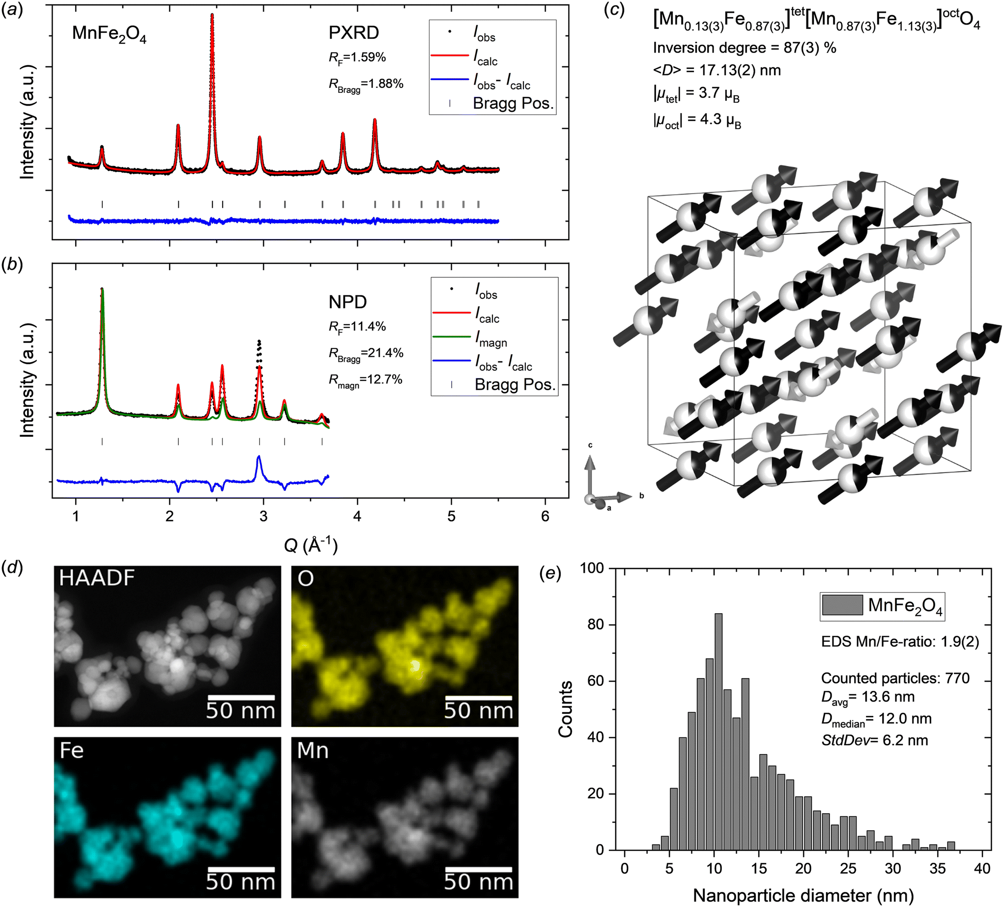 | ||
| Fig. 2 a) PXRD and b) NPD data for MnFe2O4 nanocrystallites with jointly refined Rietveld fits. c) Illustration of the refined crystal and magnetic structure of the MnFe2O4 sample. The white and black arrows indicate the relative magnitudes and orientations of the refined magnetic moment components on tetrahedral and octahedral sites, respectively. The refined atomic site occupation fractions of Mn2+ (black) and Fe3+ (white) are illustrated on the spheres. Illustration made with VESTA.26 d) STEM-HAADF image and EDS elemental maps for the MnFe2O4 nanoparticle sample. e) MnFe2O4 nanoparticle size analysis from STEM data. | ||
| MnFe2O4 | |||||||
|---|---|---|---|---|---|---|---|
| Space group: Fdm (#227) |
|||||||
| Unit cell: a = b = c = 8.49637(9) Å, α = b = γ = 90° | |||||||
| Fit quality PXRD: RBragg = 1.88%, RF = 1.59% | |||||||
| Fit quality NPD: RBragg = 21.4%, RF = 11.4%, Rmagn = 12.7% | |||||||
| Atom | Wyckoff site | x | y | z | B iso (Å2) | sof | R x (μB) |
| Note: the numbers in parentheses indicate the errors on the last significant digit of the refined parameters.a Site occupation fraction (sof).b The magnetic moment vector component (Rx = Ry = Rz) refined along the 〈111〉 direction.c The atomic displacement parameters (Biso) were constrained to be equal.d Linear restraints were imposed on the tetrahedral (8a) and octahedral (16d) site occupancies to avoid unphysical over-population and constrain to nominal composition. | |||||||
| Mn | 8a | 0.125 | 0.125 | 0.125 | 1.24(1)c | 0.13(3)d | −2.1 |
| Fe | 8a | 0.125 | 0.125 | 0.125 | 1.24(1)c | 0.87(3)d | −2.1 |
| Mn | 16d | 0.5 | 0.5 | 0.5 | 1.24(1)c | 0.44(2)d | 2.5 |
| Fe | 16d | 0.5 | 0.5 | 0.5 | 1.24(1)c | 0.56(2)d | 2.5 |
| O | 32e | 0.25695(9) | 0.25695(9) | 0.25695(9) | 1.24(1)c | 1 | 0 |
To evaluate these potential causes, various changes to the structural model were tested (see Supporting Information). Notably, free refinement of cation occupancies (Mn2+, Mn3+, Fe2+, Fe3+) and vacancy concentrations on the tetrahedral and octahedral sites is impossible due to heavy correlations leading to refinement divergence. Thus, a stable refinement can only be achieved by implementing linear restraints on composition and site occupancies (as described in the experimental section) or fixing certain parameters. The tested models include: 1) free refinement of Mn-content (site occupation fractions linearly restrained to 1.0). 2) Magnetite, i.e. Mn-deficient structure (Fe3O4). 3) Maghemite, i.e. Mn-deficient structure with disordered vacancies (γ-Fe2O3). 4) Maghemite-like structure with disordered vacancies and nominal stoichiometric Mn:Fe ratio (γ-Mn0.67Fe1.33O3). 5) Changing from divalent to trivalent Mn in the magnetic structure. However, significantly poorer fits were obtained for options 1–4 and option 5 yielded no noticeable improvement compared to the initially employed MnFe2O4 model (see ESI†). Notably, STEM-EDS maps (see Fig. 2d) show a homogeneous elemental distribution in the MnFe2O4 nanoparticles confirming the single-phase nature of the sample, and the 1:2 metal ion stoichiometry was confirmed by quantitative analysis of EDS spectra. Furthermore, in a previous study, we employed X-ray absorption spectroscopy (XAS) to confirm the oxidation states in spinel ferrite nanoparticles, including analogously prepared MnFe2O4 nanocrystallites, which confirmed divalent Mn and trivalent Fe.15 In addition, the refined cell parameter of 8.49637(9) Å is in good agreement with previous reports for stoichiometric MnFe2O4 (typically ∼8.5 Å)52,53 rather than those generally reported for Fe3O4 or γ-Fe2O3 (typically ∼8.35–8.40 Å),18,54,55 indicating that the assumptions of nominal MnFe2O4 composition in the sample, Mn2+ and Fe3+ oxidation states and no vacancies in the structure are likely correct. Consequently, despite the shortcoming of the employed model, the cause for the misfit could not be identified, and no better description could be achieved here.
The peak profile analysis yielded a mean MnFe2O4 crystallite dimension, 〈D〉, of 17.13(2) nm. The atomic structure refinement yielded an inversion degree of 87(3)%, which is significantly different from the value for bulk MnFe2O4, which is generally reported to have around 20–25% inversion.56,57 However, disordered cation distributions (inversion degrees of ∼60–70%, i.e. near-stoichiometric and disordered Mn/Fe occupancy on each site) have previously been reported for fine nanocrystallites (<10 nm).18,19
The contribution from magnetic scattering to the NPD data was modelled by implementing a collinear ferrimagnetic structure with antiparallel moments on the 8a and 16d site aligned along the 〈111〉 crystallographic direction. Concurrent and unconstrained refinement of the Mn2+ and Fe3+ Cartesian magnetic moment components on both tetrahedral and octahedral sites (together with site occupancies) introduced too many degrees of freedom and excessive parameter correlations, thereby causing refinement divergence. Consequently, the magnetic orientations were fixed to lie along the 〈111〉 direction (i.e. Rx = Ry = Rz constraint) and average moments (i.e. RMn = RFe constraint) were refined for each of the tetrahedral and octahedral sites, yielding net magnetic moments, μ = (Rx2 + Ry2 + Rz2)1/2, of |μtet| = 3.7μB and |μoct| = 4.3μB.
As mentioned earlier, the STEM-EDS maps show a homogeneous elemental distribution in the MnFe2O4 nanoparticles (see Fig. 2d) and EDS spectra collected in several different regions yielded an average Mn/Fe ratio of 1.9(2), which agrees with the formal 1:2 ratio. The STEM images (see Fig. 2d and ESI†) confirm the nanocrystalline nature and isotropic morphology of the nanoparticles. Particle size analysis was carried out by manual measurement of 770 individual particles across representative STEM micrographs taken different places on the grids. The resulting particle size distribution is shown in Fig. 2e. The obtained average particle size of 13.6 ± 6.2 nm, although somewhat smaller, is compatible with the crystallite size from the diffraction data analysis (17.13(2) nm). The discrepancy can be ascribed to the relatively broad and skewed lognormal-like size distribution, which enhances the difference between the average number weighted size from STEM analysis and volume-weighted size that is inherently obtained from diffraction data.
Crystal-, magnetic- and microstructure of CoFe2O4 nanocrystallites
Fig. 3a and b show the PXRD and NPD patterns and corresponding jointly refined Rietveld fits for the hydrothermally synthesized CoFe2O4 nanocrystallite sample. All reflections could be attributed to the spinel ferrite structure and the data show no indication of any secondary crystalline phases. Relatively good fits were obtained to both the PXRD and NPD data, however, like the MnFe2O4 sample discussed above, a considerable misfit is observed for the (400) reflection at ∼3 Å−1. The refined atomic and magnetic structure is shown in Fig. 3c and the structural parameters are provided in Table 2. The obtained cell parameter of 8.3901(1) Å is in good agreement with previously reported values for CoFe2O4 nanocrystallites, further supporting that nominal stoichiometry and phase purity have been achieved.15,18,58,59 The peak profile analysis yields a mean crystallite size of 7.92(1) nm and the atomic structure refinement indicates an almost fully inverse spinel structure with an inversion degree of 95.4(6)%. This value is in agreement with the known bulk preference for the inverse configuration,17 although nanosized CoFe2O4 crystallites have been reported to adopt mixed spinel structures.18,59 This could indicate a size- and/or synthesis method-dependent nature of the cation configuration in CoFe2O4. The collinear ferrimagnetic structure was refined along the 〈100〉 crystallographic direction given the hard magnetic properties of the compound (see experimental section), with net magnetic moments of 3.5 and 3.6μB obtained for the tetrahedral and octahedral sites, respectively.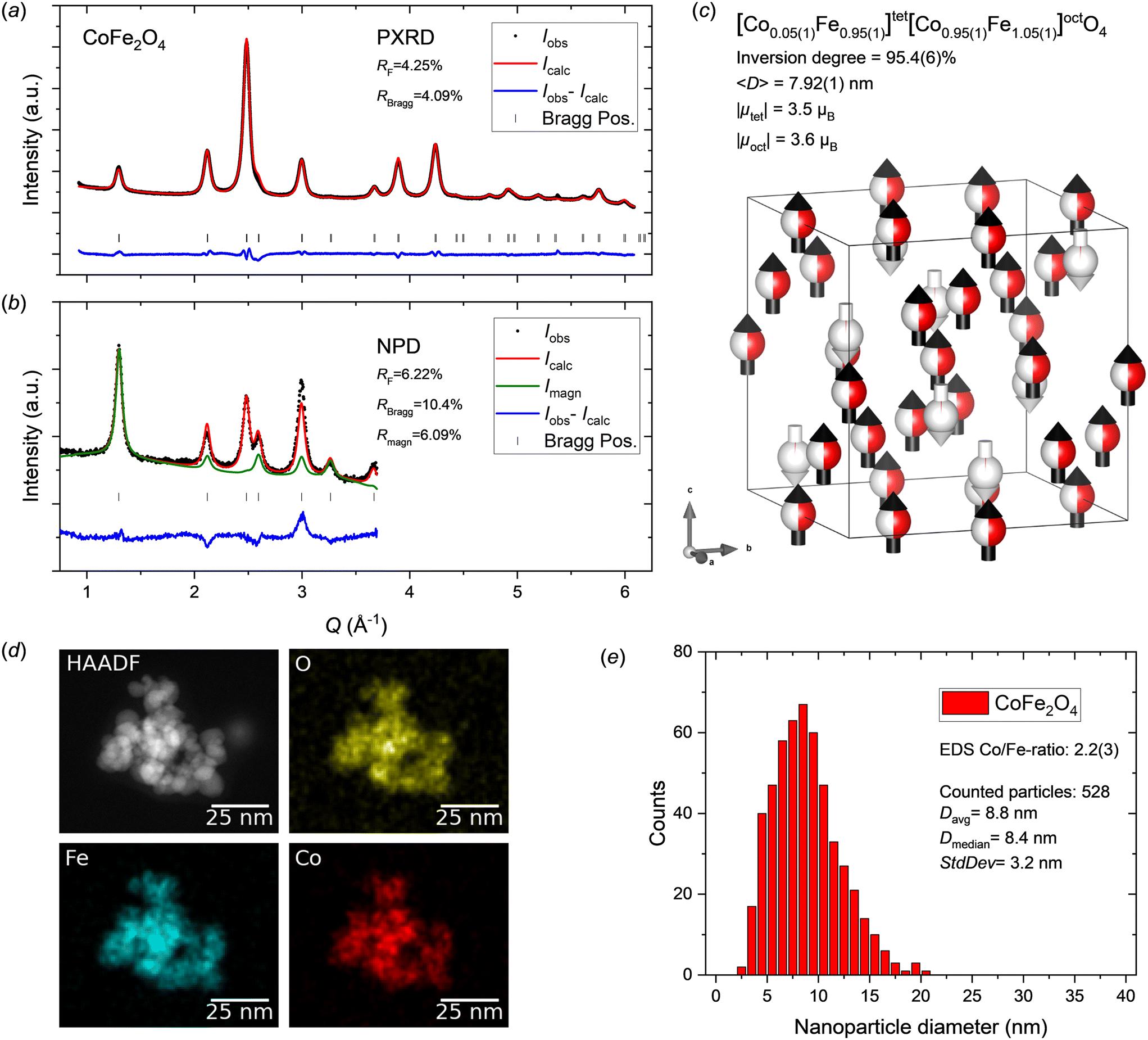 | ||
| Fig. 3 a) PXRD and b) NPD data for CoFe2O4 nanocrystallites with jointly refined Rietveld fits. c) Illustration of the refined crystal and magnetic structure of the CoFe2O4 sample. The white and black arrows indicate the relative magnitudes and orientations of the refined magnetic moment components on tetrahedral and octahedral sites, respectively. The refined atomic site occupation fractions of Co2+ (red) and Fe3+ (white) are illustrated on the spheres. Illustration made with VESTA.26 d) STEM-HAADF image and EDS elemental maps for the CoFe2O4 nanoparticle sample. e) CoFe2O4 nanoparticle size analysis from STEM data. | ||
| CoFe2O4 | |||||||
|---|---|---|---|---|---|---|---|
| Space group: Fdm (#227) |
|||||||
| Unit cell: a = b = c = 8.3901(1) Å, α = b = γ = 90° | |||||||
| Fit quality PXRD: RBragg = 4.09%, RF = 4.25% | |||||||
| Fit quality NPD: RBragg = 10.4%, RF = 6.22%, Rmagn = 6.09% | |||||||
| Atom | Wyckoff site | x | y | z | B iso (Å2) | sof | R x (μB) |
| Note: the numbers in parentheses indicate the errors on the last significant digit of the refined parameters.a Site occupation fraction (sof).b The magnetic moment vector component (Rx) refined along the 〈100〉 direction.c The atomic displacement parameters (Biso) were constrained to be equal.d Linear restraints were imposed on the tetrahedral (8a) and octahedral (16d) site occupancies to avoid unphysical over-population and constrain to nominal composition. | |||||||
| Co | 8a | 0.125 | 0.125 | 0.125 | 1.09(1)c | 0.046(6)d | −3.5 |
| Fe | 8a | 0.125 | 0.125 | 0.125 | 1.09(1)c | 0.954(6)d | −3.5 |
| Co | 16d | 0.5 | 0.5 | 0.5 | 1.09(1)c | 0.477(3)d | 3.6 |
| Fe | 16d | 0.5 | 0.5 | 0.5 | 1.09(1)c | 0.523(3)d | 3.6 |
| O | 32e | 0.25634(8) | 0.25634(8) | 0.25634(8) | 1.09(1)c | 1 | 0 |
The elemental mapping by STEM-EDS shows a homogeneous distribution of the metal ions in the CoFe2O4 nanoparticles (see Fig. 3d), which is consistent with a single-phase sample. Quantitative analysis of EDS spectra collected in several different regions yielded an average Co/Fe ratio of 2.2(3), which agrees well with the formal 1:2 metal ion stoichiometry. The nanocrystalline nature and isotropic morphology of the nanoparticles were confirmed by the STEM images (see Fig. 3d and ESI†). Particle size analysis was carried out by manual measurement of 528 individual particles across representative STEM micrographs taken different places on the grids. The resulting particle size distribution is shown in Fig. 3e. The average particle size of 8.8 ± 3.2 nm agrees well with the nanocrystallite size obtained from the diffraction data analysis (7.92(1) nm).
Crystal-, magnetic- and microstructure of NiFe2O4 nanocrystallites
Fig. 4a and b show the jointly refined PXRD and NPD patterns collected on the NiFe2O4 nanocrystallites. The diffraction data show no indications of secondary crystalline phases and relatively good fits were obtained for both the PXRD and NPD patterns, including the (400) peak of the NPD data, which was not fully described for the MnFe2O4 and CoFe2O4 samples. The refined crystal- and magnetic structure is illustrated in Fig. 4c and the structural parameters are provided in Table 3. A cubic cell parameter of 8.3574(1) Å was obtained, which is in good agreement with previously reported values for NiFe2O4 (∼8.33–8.36 Å).60–63 In the bulk, NiFe2O4 is an inverse spinel,17 however, both inverse and mixed spinel structures have been reported for nanosized crystallites,18,20–22 indicating a potential dependence on particle size or synthesize route. Here, the initial linearly restrained refinement of the site occupancies led to a slight unphysical overpopulation of Ni2+ on the 16d site and under population on the 8a site, indicating a strong preference for the inverse spinel configuration. Therefore, the site occupations were fixed to the fully inverse distribution in the final refinement. The peak profile analysis yielded a mean crystallite size of 10.31(1) nm. Given that NiFe2O4 is a soft magnetic material, the atomic magnetic moment components were refined along the theoretically preferred space diagonal of the cubic unit cell (〈111〉 direction). Net moments of 3.6 and 3.1μB were obtained for the 8a and 16d sites, respectively.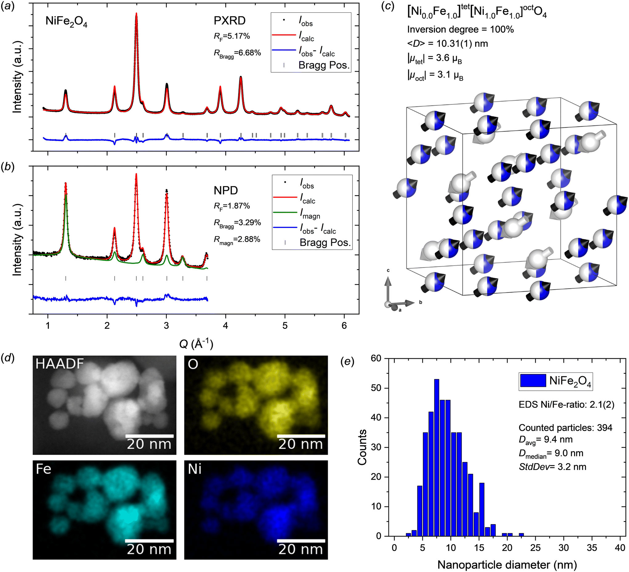 | ||
| Fig. 4 a) PXRD and b) NPD data for NiFe2O4 nanocrystallites with jointly refined Rietveld fits. c) Illustration of the refined crystal and magnetic structure of the NiFe2O4 sample. The white and black arrows indicate the relative magnitudes and orientations of the refined magnetic moment components on tetrahedral and octahedral sites, respectively. The atomic site occupation fractions of Ni2+ (blue) and Fe3+ (white) are illustrated on the spheres. Illustration made with VESTA.26 d) STEM-HAADF image and EDS elemental maps for the NiFe2O4 nanoparticle sample. e) NiFe2O4 nanoparticle size analysis from STEM data. | ||
| NiFe2O4 | |||||||
|---|---|---|---|---|---|---|---|
| Space group: Fdm (#227) |
|||||||
| Unit cell: a = b = c = 8.3574(1) Å, α = b = γ = 90° | |||||||
| Fit quality PXRD: RBragg = 6.68%, RF = 5.17% | |||||||
| Fit quality NPD: RBragg = 3.29%, RF = 1.87%, Rmagn = 2.88% | |||||||
| Atom | Wyckoff site | x | y | z | B iso (Å2) | sof | R x (μB) |
| Note: the numbers in parentheses indicate the errors on the last significant digit of the refined parameters.a Site occupation fraction (sof).b The magnetic moment vector component (Rx = Ry = Rz) refined along the 〈111〉 direction.c The atomic displacement parameters (Biso) were constrained to be equal. | |||||||
| Ni | 8a | 0.125 | 0.125 | 0.125 | 0.66(1)c | 0 | −2.1 |
| Fe | 8a | 0.125 | 0.125 | 0.125 | 0.66(1)c | 1 | −2.1 |
| Ni | 16d | 0.5 | 0.5 | 0.5 | 0.66(1)c | 0.5 | 1.8 |
| Fe | 16d | 0.5 | 0.5 | 0.5 | 0.66(1)c | 0.5 | 1.8 |
| O | 32e | 0.25841(9) | 0.25841(9) | 0.25841(9) | 0.66(1)c | 1 | 0 |
The STEM-EDS maps of the NiFe2O4 nanoparticles show an even homogeneous distribution of Ni and Fe in the sample (see Fig. 4d) corroborating the single-phase nature. The 1:2 metal ion stoichiometry of the Ni spinel ferrite compound was confirmed by quantitative analysis of EDS spectra collected in several different regions yielding an average Ni/Fe ratio of 2.1(2). The STEM images (see Fig. 4d and ESI†) confirm the nanocrystalline nature and isotropic morphology of the nanoparticles. Particle size analysis was carried out by manual measurement of 394 individual particles across representative TEM micrographs taken different places on the grids. The resulting particle size distribution is shown in Fig. 4e. The obtained average particle size of 9.4 ± 3.2 nm is agreement with crystallite dimension from the diffraction data analysis (10.31(1) nm).
Crystal-, magnetic- and microstructure of ZnFe2O4 nanocrystallites
The PXRD and NPD patterns of the ZnFe2O4 nanocrystallite sample and the corresponding Rietveld fits are shown in Fig. 5a and b. As evident from the highly broadened diffraction peaks, the ZnFe2O4 sample consists of ultrafine crystallites (〈D〉 = 3.70(1) nm). The diffraction data do not show any additional crystalline phases to be present in the sample as all peaks are well described by the spinel structure model. The refined crystal- and magnetic structure is illustrated in Fig. 5c and the structural parameters are provided in Table 4. A cell parameter of 8.4588(4) is obtained, which agrees with the relatively large variety of previously reported values for ZnFe2O4 nanoparticles (∼8.39–8.45 Å), when considering the very small particles size, which often causes some cell expansion due to the increased surface/bulk ratio.18,23,64,65 A spinel inversion of 13.8(4)% is obtained from the refinement, which differs from the thermodynamically stable normal spinel configuration,17 but falls within the various degrees of inversion between 0 and 0.6 that have been reported for nanosized crystallites in the literature.18,23,24 At first glance, the combination of an almost completely normal spinel structure, with the majority of non-magnetic Zn2+ on the tetrahedral site, could be expected to yield a highly optimized intrinsic magnetic performance. However, the very low amount of a magnetic species (Fe3+) on the tetrahedral site leads to a destabilization of the magnetic structure due to the weak antiferromagnetic tetrahedral–octahedral superexchange coupling. This causes the material to be paramagnetic at room temperature (as evident from the magnetization data discussed later) and is the reason for the very weak magnetic scattering observed. At very low temperature (<10 K), ZnFe2O4 forms a long-range antiferromagnetic structure, as the low thermal energy allows extended antiferromagnetic superexchange coupling between the octahedral Fe3+ moments.66 Here, despite the largely paramagnetic nature of the sample, the small magnetic scattering contribution was modelled based on a collinear ferrimagnetic structure along the 〈111〉 crystallographic direction, yielding small net moments of 1.9 and 1.5μB on the tetrahedral and octahedral sites, respectively. The small amount of long-range magnetic diffraction signal present can be ascribed to a slight magnetic ordering induced by the small amount of tetrahedral Fe3+, which results in regions with sufficient coherently scattering magnetic ordering. | ||
| Fig. 5 a) PXRD and b) NPD data for ZnFe2O4 nanocrystallites with jointly refined Rietveld fits. c) Illustration of the refined crystal and magnetic structure of the ZnFe2O4 sample. The refined magnetic moment components on tetrahedral and octahedral sites are too small to be illustrated. The refined atomic site occupation fractions of Zn2+ (green) and Fe3+ (white) are illustrated on the spheres. The displayed arrows have been scaled ×2 compared to the other structural illustrations to make them visible. Illustration made with VESTA.26 d) STEM-HAADF image and EDS elemental maps for the ZnFe2O4 nanoparticle sample. e) ZnFe2O4 nanoparticle size analysis from STEM data. | ||
| ZnFe2O4 | |||||||
|---|---|---|---|---|---|---|---|
| Space group: Fdm (#227) |
|||||||
| Unit cell: a = b = c = 8.4588(4) Å, α = b = γ = 90° | |||||||
| Fit quality PXRD: RBragg = 1.48%, RF = 1.41% | |||||||
| Fit quality NPD: RBragg = 4.20%, RF = 2.37%, Rmagn = 5.01% | |||||||
| Atom | Wyckoff site | x | y | z | B iso (Å2) | sof | R x (μB) |
| Note: the numbers in parentheses indicate the errors on the last significant digit of the refined parameters.a Site occupation fraction (sof).b The magnetic moment vector component (Rx = Ry = Rz) refined along the 〈111〉 direction.c The atomic displacement parameters (Biso) were constrained to be equal.d Linear restraints were imposed on the tetrahedral (8a) and octahedral (16d) site occupancies to avoid unphysical over-population and constrain to nominal composition. | |||||||
| Zn | 8a | 0.125 | 0.125 | 0.125 | 0.51(2)c | 0.862(4)d | 0 |
| Fe | 8a | 0.125 | 0.125 | 0.125 | 0.51(2)c | 0.138(4)d | −8.1 |
| Zn | 16d | 0.5 | 0.5 | 0.5 | 0.51(2)c | 0.069(2)d | 0 |
| Fe | 16d | 0.5 | 0.5 | 0.5 | 0.51(2)c | 0.931(2)d | 0.9 |
| O | 32e | 0.2489(3) | 0.2489(3) | 0.2489(3) | 0.51(2)c | 1 | 0 |
Fig. 5d shows a representative STEM-EDS map illustrating the homogeneous elemental distribution in the ZnFe2O4 nanoparticles. The expected 1:2 metal ion stoichiometry was confirmed by quantitative analysis of EDS spectra collected in several different regions yielding an average Zn/Fe ratio of 2.3(4). The nanocrystalline nature and isotropic morphology of the nanoparticles are confirmed by the TEM images (see Fig. 5d and ESI†). Particle size analysis was carried out by manual measurement of 165 individual particles across representative STEM micrographs taken different places on the grids. The resulting particle size distribution is shown in Fig. 5e. The obtained average particle size of 5.1 ± 1.6 nm is compatible with the crystallite size from the diffraction data analysis (3.70(1) nm).
Magnetic properties
The magnetic hysteresis curves of the four samples collected by VSM are shown in Fig. 6a, illustrating their distinct magnetic behaviour as a result of their different atomic- and nano-structural natures. The MnFe2O4 (Ms = 63.0(1) Am2 kg−1), CoFe2O4 (Ms = 64.2(1) Am2 kg−1) and NiFe2O4 (Ms = 50.2(1) Am2 kg−1) nanocrystallite samples exhibit magnetic responses characteristic of soft magnets, while the ZnFe2O4 (Ms = 6.1(1) Am2 kg−1) sample is paramagnetic. Notably, bulk CoFe2O4 is known to exhibit semi-hard magnetic properties with an effective magnetocrystalline anisostropy constant, K1, of 290 kJ m−3 and a Curie temperature, TC, of 790 °C.27 Thus, the lack of a coercive field indicates that the dimensions of the synthesized CoFe2O4 particles are below the superparamagnetic limit. The spin reversal time, τ, for superparamagnetic nanoparticles can be estimated by the Néel–Brown law, τ = τ0exp(K1V/kBT), where τ0 is the attempt time (∼1 ns), kB is the Boltzmann constant, V is the crystallite volume, and T is the temperature.28,67 For isotropic crystallites, the critical superparamagnetic threshold diameter Dsp can be obtained from the Néel–Brown law as follows: Dsp = [6kBTln[τ/τ0]/(πK1)]1/3. By setting the spin reversal time equal to the VSM measurement averaging time (2 s), a critical dimension of ∼8.4 nm is obtained for CoFe2O4 at 300 K. The average crystallite size of 7.92(1) nm obtained from peak profile analysis of the diffraction data is therefore below the superparamagnetic limit and in agreement with the observed lack of magnetic hysteresis. The slight opening of the hysteresis loop for the CoFe2O4 sample illustrated in the insert of Fig. 6a (Hc = 13.2(2) kA m−1) can be attributed to polydispersity with a minor part of the crystallites having sizes above the critical dimension.
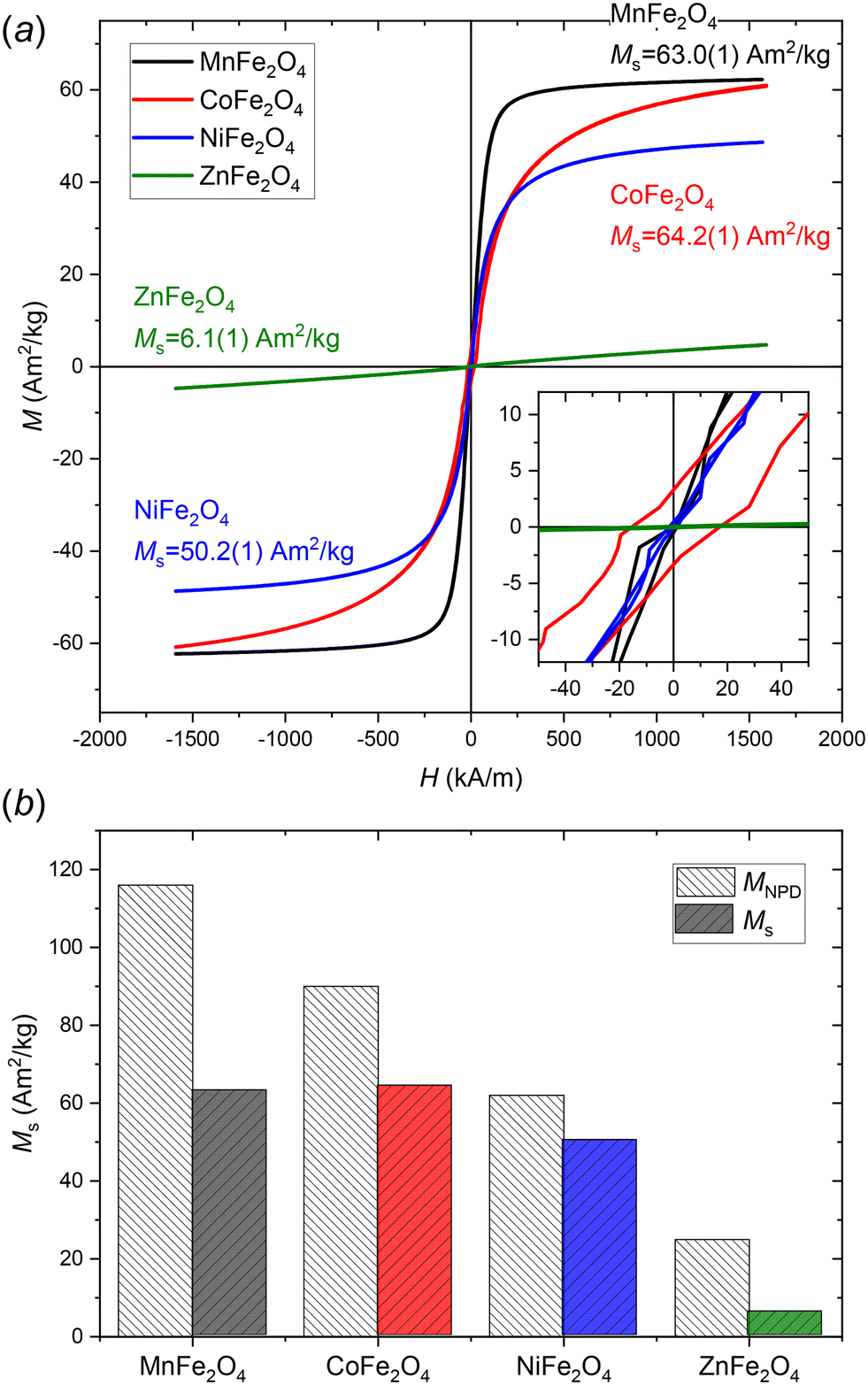 | ||
| Fig. 6 a) Room temperature field dependent magnetisation curves of the MnFe2O4, CoFe2O4, NiFe2O4, and ZnFe2O4 nanoparticles with saturation magnetisations, Ms, (determined by law of approach to saturation) indicated. b) Comparison of intrinsic magnetizations estimated from the magnetic structure refinement of the NPD data (MNPD) and the macroscopic saturation magnetizations from the VSM data (Ms). | ||
The magnetic properties of spinel ferrites depend on a combination of factors, including the type of divalent ion, the spinel inversion degree, and the crystallite size.17 As demonstrated in our previous studies, the inversion degree of spinel ferrite nanoparticles may differ significantly from their bulk counterparts and may vary considerably depending on employed synthesis conditions and/or with thermal history.15,29,68Fig. 6b compares the saturation magnetizations calculated from the refinements of structure and magnetic moment in the NPD, MNPD, to the observed macroscopic saturation magnetizations, Ms, from the VSM data. The MNPD value may be used as an estimate for the upper-limit intrinsic saturation magnetization permitted by the structure for a fully crystalline sample. Although the magnetizations from the two methods follow similar trends, the plot also illustrates the somewhat limited agreement between the two approaches and the relatively poor predictive capability of the MNPD value. This may be due to several factors, including the very high uncertainties of the magnetic structure refinement, reduced crystallinity of the sample, and the influence of microstructural and finite-size effects.30,31
Discussion
All of the ferrite samples studied here (MnFe2O4, CoFe2O4, NiFe2O4, and ZnFe2O4) were confirmed to be spinel structured, nanosized and phase pure (i.e. no crystalline impurities observed). To ensure the formation of phase-pure spinel ferrites without impurities such as hematite (α-Fe2O4) or manganese oxides, several key parameters were carefully controlled. A precise stoichiometry of the metal ions was maintained to match the target spinel compositions, ensuring a balanced cation distribution. Uniform mixing of the precursor species was achieved through constant magnetic stirring during the dropwise addition of 25% NH4OH, which provided a moderately basic environment (pH ≈ 10). This pH was critical for promoting the precipitation of homogeneous FeOOH and M(OH)2 gels, especially for MnFe2O4, where excessive alkalinity could lead to manganese oxide impurities.34,35 The presence of divalent transition metal species in the precursor mixture further ensured spinel phase formation, as highlighted by our earlier study showing their role in preventing α-Fe2O3 crystallization.69The obtained crystallite sizes, unit cell lengths, cation inversion degrees and saturation magnetisations of the samples from this study are summarised in Table 5, where they are compared to values from our previous studies employing different precursor routes and/or synthesis conditions.15,29 Variations in cell parameters (PXRD peak positions) and crystallite/particle size (PXRD peak widths and STEM analysis) caused by the distinct chemistries of the different divalent transition metal ions are observed. In the present study, all precursors were equivalently prepared by the NH4OH method described earlier, and treated at identical physical reaction conditions, i.e. in an autoclave reactor at 200 °C for 1 h. However, in the previous studies various adjustments to the procedure were done, as indicated for the specific cases below, to promote certain product characteristics. The stronger NaOH base is often used as the precipitating agent in hydrothermal spinel ferrite synthesis, however, the NH4OH precursor preparation route was used for the preparation of MnFe2O4 nanocrystallites in both this and our previous study. This is because the NaOH route does not yield phase pure MnFe2O4 samples, but instead leads to formation of a considerable amount of α-Fe2O3 impurity. Here, a higher synthesis temperature of 200 °C was used, which is found to cause formation of larger MnFe2O4 crystallites of 17.13(2) nm compared to 13.5(2) nm obtained at 150 °C. In addition, the higher temperature yields a higher inversion degree of 0.87(3) compared to the 0.643(3) obtained at 150 °C. A small increase in Ms is also observed. Since Mn2+ and Fe3+ ions have identical ground state 3d5 electron configurations, the increased Ms is likely a result of the larger crystallite size.
| Compound | Study | Base type | Synthesis conditions | Crystallite size (nm) | Unit cell length (Å) | Inversion deg. | M s (Am2 kg−1) |
|---|---|---|---|---|---|---|---|
| a Weighted average from bimodal size model. | |||||||
| MnFe2O4 | This study | 25% NH4OH (pH = 10) | AC, 200 °C, 1 h | 17.13(2) | 8.49637(9) | 0.87(3) | 63.0(1) |
| Study 1 (ref. 15) | 25% NH4OH (pH = 10) | AC, 150 °C, 1 h | 13.5(2)a | 8.46(12) | 0.643(3) | 60.5(1) | |
| CoFe2O4 | This study | 25% NH4OH (pH = 10) | AC, 200 °C, 1 h | 7.92(1) | 8.3901(1) | 0.954(6) | 64.2(1) |
| Study 1 (ref. 15) | 12 M NaOH (pH > 14) | AC, 200 °C, 1 h | 13.4(1) | 8.4018(1)a | 0.660(6) | 71.7(2) | |
| Study 2 (ref. 29) | 16 M NaOH (pH > 14) | AC, 240 °C, 2 h | 17.6(1) | 8.3897(2) | 0.72(1) | 74.0(2) | |
| NiFe2O4 | This study | 25% NH4OH | AC, 200 °C, 1 h | 10.31(1) | 8.3574(1) | 1 | 50.2(1) |
| Study 1 (ref. 15) | 12 M NaOH (pH > 14) | AC, 200 °C, 1 h | 23.7(17)a | 8.36(12)a | 1 | 47.1(1) | |
| ZnFe2O4 | This study | 25% NH4OH | AC, 200 °C, 1 h | 3.70(1) | 8.4588(4) | 0.138(4) | 6.1(1) |
| Study 1 (ref. 15) | 12 M NaOH (pH > 14) | Flow (250 bar), 390 °C | 9.8(1) | 8.4376(3) | 0.166(10) | 10.8(1) | |
| Study 2 (ref. 29) | 16 M NaOH (pH > 14) | AC, 240 °C, 2 h | 11.0(1) | 8.4515(2) | 0.24(1) | 20.5(1) | |
For CoFe2O4, the NaOH precursor route was used in two previous studies with different base concentrations of 12 M and 16 M, respectively. The syntheses were carried out with identical physical reaction conditions in Study 1 (200 °C for 1 h) and at higher temperature and for longer time in Study 2 (240 °C for 2 h). The NH4OH route yields much smaller crystallites of 7.92(1) nm compared to the 13.4(1) nm obtained using the 12 M NaOH route at identical synthesis conditions (200 °C, 1 h) and 17.6(1) nm using the stronger 16 M NaOH route for longer time and at higher temperature (240 °C, 2 h). This is consistent with observations in a previous in situ PXRD study of hydrothermal CoFe2O4 nanoparticle formation, where changing precursor pH or precursor concentration at the time of adding the precipitating base, proved to be a more efficient handle for changing particle sizes compared to varying synthesis temperature.69 In the bulk, CoFe2O4 adopts a fully inverse spinel structure, i.e. Co2+ occupying half the octahedral sites. However, our structural studies of hydrothermally synthesised CoFe2O4 nanocrystallites consistently indicate that metastable mixed spinel cation configurations are obtained.15,29 Interestingly, the smaller crystallites from the NH4OH route exhibit a higher inversion degree of 0.954(6), which is closer to the thermodynamically stable fully inverse structure of the bulk compound, compared to the almost random/disordered distribution of 0.660(6) and 0.72(1) from the NaOH routes. Using a softer base may thus be less likely to induce formation of metastable cation configurations. The CoFe2O4 nanoparticles prepared through the NH4OH route yield a lower Ms of 64.2(1) Am2 kg−1 compared to the 71.7(2) and 74.0(2) Am2 kg−1 produced by the NaOH routes. The Ms drop can be attributed to the higher inversion degree (i.e. a larger amount of the less magnetic 3d7 Co2+ ions replacing 3d5 Fe3+ on the octahedral site) along with the smaller crystallite size.
In the case of NiFe2O4, identical physical reaction conditions (i.e. autoclave reactor at 200 °C for 1 h) were used for the two different precursors of the present and previous study. As for CoFe2O4, a considerable difference in the obtained crystallite sizes is observed, with the NH4OH precursor route yielding smaller 10.31(1) nm NiFe2O4 crystallites compared to 23.7(17) nm from the NaOH route. As in our previous studies using the NaOH route, refining the cation occupancies in the modelling of the diffraction data led to unphysical excess occupation by Ni on the octahedral site indicating a fully inverse structure.15,68 Consequently, NiFe2O4 seemingly has a very strong affinity for the fully inverse spinel structure even for small crystallites of ∼10 nm. Interestingly, despite the smaller crystallite size, a slightly larger Ms of 50.2(1) Am2 kg−1 is obtained for the NH4OH synthesized particles compared to 47.1(1) Am2 kg−1 for the larger particles from the NaOH synthesis.
For ZnFe2O4, our two previous studies both used the NaOH precursor preparation route. In one case, 12 M NaOH was employed and the synthesis was carried out under supercritical hydrothermal conditions (390 °C, 250 bar) in a continuous flow reactor.15,70 In the other case, the precursor preparation was done using a stronger 16 M NaOH solution and the synthesis carried out in an autoclave reactor at 240 °C for 2 h.29 Here, the combination of using a softer NH4OH base in the precursor preparation and carrying out the synthesis at a lower reaction temperature of 200 °C yields very fine ZnFe2O4 crystallites with an average diameter of 3.70(1) nm. For the NaOH studies, larger crystallites of 9.8(1) and 11.0(1) nm were obtained. In the bulk, ZnFe2O4 adopts a normal spinel structure, i.e. with Zn2+ exclusively occupying the tetrahedral site. However, for the nanosized crystallites a metastable mixed spinel configuration is consistently obtained. As for the CoFe2O4 samples, it seems that using a softer base causes a more bulk-like cation configuration with an inversion degree of 0.138(4) compared to the 0.24(1) obtained from the 16 M NaOH route. Since Zn2+ ions (3d10 electron configuration) are non-magnetic, bulk ZnFe2O4 in the thermodynamically stable normal spinel configuration adopts an antiferromagnetic structure with a Néel temperature, TN, of 10 K, i.e. paramagnetic at room temperature.28,66 However, deviations from the normal spinel configuration undoes the perfect cancellation of the antiparallel 3d5 Fe3+ magnetic moments on the octahedral sites. Consequently, the nanocrystallites from our previous studies, with a higher degree of cation disorder, exhibit a higher saturation magnetisation than the crystallites with a more “normal” cation configuration.
Conclusion
The crystal and magnetic structures of hydrothermally synthesized MnFe2O4, CoFe2O4, NiFe2O4 and ZnFe2O4 nanocrystallites have been examined using joint structural modelling of PXRD and NPD data. By using weak 25% NH4OH as the precipitating base in the precursor preparations it was possible to prepare phase-pure MnFe2O4, CoFe2O4, NiFe2O4 and ZnFe2O4 nanocrystallites employing identical hydrothermal synthesis conditions. This, in turn, allowed us to isolate and study the effect of the individual divalent ions on the obtained crystallite size and structure. The data reveals a substantial effect of the type of cation on the resulting nanocrystallite size, spinel cation configurations and magnetic structure/properties. The study highlights how a detailed fundamental understanding of the synthesis-structure–property relationship is essential for accurately predicting, designing, and tailoring spinel ferrite materials with specific or optimized properties.Data availability
The data supporting this article are included in the article and ESI.†Conflicts of interest
The authors declare no competing financial interests.Acknowledgements
The authors are grateful for the obtained beamtime at the Cold Neutron Powder Diffractometer (DMC) instrument at the Swiss Spallation Neutron Source (SINQ), Paul Scherrer Institute (PSI), Villigen, Switzerland. Lukas Keller and Emmanuel Canévet are thanked for their support during the beamtime. This work was financially supported by the Danish National Research Foundation (Center for Materials Crystallography, DNRF93), Innovation Fund Denmark (Green Chemistry for Advanced Materials, GCAM-4107-00008B), Independent Research Fund Denmark (Small and Smart Magnet Design), Danish Center for Synchrotron and Neutron Science (DanScatt), and Comunidad de Madrid, Spain, through an “Atracción de Talento Investigador” fellowship (2020-T2/IND-20581). C. G.-M. acknowledges financial support from grant RYC2021–031181-I funded by MCIN/AEI/10.13039/501100011033 and by the “European Union NextGenerationEU/PRTR”. This project has received funding from the European Union's Horizon Europe research and innovation programme under grant agreement No 101063369 (OXYPOW) and No 101109595 (MAGWIRE). Affiliation with the Center for Integrated Materials Research (iMAT) at Aarhus University is gratefully acknowledged. EDB and RK acknowledge funding from the Carlsberg Foundation (CF18-0705), Aarhus University Centre for Integrated Materials Research and the Interdisciplinary Nanoscience Center.References
- J. M. D. Coey, J. Magn. Magn. Mater., 2002, 248, 441–456 CrossRef CAS.
- Q. Song and Z. J. Zhang, J. Am. Chem. Soc., 2012, 134, 10182–10190 CrossRef CAS.
- A. Quesada, C. Granados-Miralles, A. Lopez-Ortega, S. Erokhin, E. Lottini, J. Pedrosa, A. Bollero, A. M. Aragon, F. Rubio-Marcos, M. Stingaciu, G. Bertoni, C. D. J. Fernandez, C. Sangregorio, J. F. Fernandez, D. Berkov and M. Christensen, Adv. Electron. Mater., 2016, 2, 1500365 CrossRef.
- Q. A. Pankhurst, J. Connolly, S. K. Jones and J. Dobson, J. Phys. D: Appl. Phys., 2003, 36, R167–R181 CrossRef CAS.
- C. C. Berry and A. S. G. Curtis, J. Phys. D: Appl. Phys., 2003, 36, R198–R206 CrossRef CAS.
- M. de h-Óra, A. Nicolenco, P. Monalisha, T. Maity, B. Zhu, S. Lee, Z. Sun, J. Sort and J. MacManus-Driscoll, APL Mater., 2023, 11, 051105 CrossRef.
- Y. Yang, Z. Xi, Y. Dong, C. Zheng, H. Hu, X. Li, Z. Jiang, W.-C. Lu, D. Wu and Z. Wen, ACS Appl. Mater. Interfaces, 2020, 12, 56300–56309 CrossRef CAS PubMed.
- D. Guin, B. Baruwati and S. V. Manorama, Org. Lett., 2007, 9, 1419–1421 CrossRef CAS PubMed.
- R. Abu-Reziq, H. Alper, D. S. Wang and M. L. Post, J. Am. Chem. Soc., 2006, 128, 5279–5282 CrossRef CAS PubMed.
- J. H. Lee, Y. M. Huh, Y. Jun, J. Seo, J. Jang, H. T. Song, S. Kim, E. J. Cho, H. G. Yoon, J. S. Suh and J. Cheon, Nat. Med., 2007, 13, 95–99 CrossRef CAS PubMed.
- H. B. Na, I. C. Song and T. Hyeon, Adv. Mater., 2009, 21, 2133–2148 CrossRef CAS.
- J. T. Jang, H. Nah, J. H. Lee, S. H. Moon, M. G. Kim and J. Cheon, Angew. Chem., Int. Ed., 2009, 48, 1234–1238 CrossRef CAS PubMed.
- C. A. Quinto, P. Mohindra, S. Tong and G. Bao, Nanoscale, 2015, 7, 12728–12736 RSC.
- A. H. Lu, E. L. Salabas and F. Schuth, Angew. Chem., Int. Ed., 2007, 46, 1222–1244 CrossRef CAS PubMed.
- H. L. Andersen, M. Saura-Múzquiz, C. Granados-Miralles, E. Canévet, N. Lock and M. Christensen, Nanoscale, 2018, 10, 14902–14914 RSC.
- K. R. Sanchez-Lievanos, J. L. Stair and K. E. Knowles, Inorg. Chem., 2021, 60, 4291–4305 CrossRef CAS PubMed.
- S. S. Chikazumi and C. D. Graham, Physics of ferromagnetism, Oxford University Press, Oxford, New York, 2nd edn, 2009 Search PubMed.
- E. Solano, C. Frontera, T. Puig, X. Obradors, S. Ricart and J. Ros, J. Appl. Crystallogr., 2014, 47, 414–420 CrossRef CAS.
- C. Liu, B. S. Zou, A. J. Rondinone and Z. J. Zhang, J. Phys. Chem. B, 2000, 104, 1141–1145 CrossRef CAS.
- J. Jacob and M. A. Khadar, J. Appl. Phys., 2010, 107, 114310 CrossRef.
- S. M. Patange, S. E. Shirsath, G. S. Jangam, K. S. Lohar, S. S. Jadhav and K. M. Jadhav, J. Appl. Phys., 2011, 109, 053909 CrossRef.
- Z. Z. Lazarevic, C. Jovalekic, A. Milutinovic, D. Sekulic, V. N. Ivanovski, A. Recnik, B. Cekic and N. Z. Romcevic, J. Appl. Phys., 2013, 113, 187221 CrossRef.
- T. Slatineanu, A. R. Iordan, M. N. Palamaru, O. F. Caltun, V. Gafton and L. Leontie, Mater. Res. Bull., 2011, 46, 1455–1460 CrossRef CAS.
- V. Blanco-Gutierrez, E. Climent-Pascual, M. J. Torralvo-Fernandez, R. Saez-Puche and M. T. Fernandez-Diaz, J. Solid State Chem., 2011, 184, 1608–1613 CrossRef CAS.
- Á. Gallo-Cordova, A. Espinosa, A. Serrano, L. Gutiérrez, N. Menéndez, M. del Puerto Morales and E. Mazarío, Mater. Chem. Front., 2020, 4, 3063–3073 RSC.
- K. Momma and F. Izumi, J. Appl. Crystallogr., 2011, 44, 1272–1276 CrossRef CAS.
- J. M. D. Coey, Magnetism and magnetic materials, Cambridge University Press, Cambridge, 2010 Search PubMed.
- R. Skomski, J. Phys.: Condens. Matter, 2003, 15, R841–R896 CrossRef CAS.
- H. L. Andersen, C. Granados-Miralles, M. Saura-Múzquiz, M. Stingaciu, J. Larsen, F. Søndergaard-Pedersen, J. V. Ahlburg, L. Keller, C. Frandsen and M. Christensen, Mater. Chem. Front., 2019, 3, 668–679 RSC.
- B. Xavier and L. Amílcar, J. Phys. D: Appl. Phys., 2002, 35, 201 CrossRef.
- S. Linderoth, P. V. Hendriksen, F. Bødker, S. Wells, K. Davies, S. W. Charles and S. Mørup, J. Appl. Phys., 1994, 75, 6583–6585 CrossRef CAS.
- B. Zhang, G. Tang, Z. Yan, Z. Wang, Q. Yang and J. Cui, J. Wuhan Univ. Technol., Mater. Sci. Ed., 2007, 22, 514–517 CrossRef CAS.
- W. Clegg, Crystal structure analysis: principles and practice, International Union of Crystallography; Oxford University Press, Chester, England, New York, 2001 Search PubMed.
- Z. Wang, X. Guo, J. Montoya and J. K. Nørskov, npj Comput. Mater., 2020, 6, 160 CrossRef.
- J. B. Gerken, J. G. McAlpin, J. Y. C. Chen, M. L. Rigsby, W. H. Casey, R. D. Britt and S. S. Stahl, J. Am. Chem. Soc., 2011, 133, 14431–14442 CrossRef CAS PubMed.
- W. Sun, D. A. Kitchaev, D. Kramer and G. Ceder, Nat. Commun., 2019, 10, 573 CrossRef CAS PubMed.
- J. Schefer, P. Fischer, H. Heer, A. Isacson, M. Koch and R. Thut, Nucl. Instrum. Methods Phys. Res., Sect. A, 1990, 288, 477–485 CrossRef.
- J. Rodriguez-Carvajal, Phys. B, 1993, 192, 55–69 CrossRef CAS.
- P. Thompson, D. E. Cox and J. B. Hastings, J. Appl. Crystallogr., 1987, 20, 79–83 CrossRef CAS.
- P. Scherrer, Nachrichten von der Gesellschaft der Wissenschaften zu Göttingen, Mathematisch-Physikalische Klasse, 1918, vol. 1918, pp. 98–100 Search PubMed.
- J. I. Langford and A. J. C. Wilson, J. Appl. Crystallogr., 1978, 11, 102–113 CrossRef CAS.
- G. Shirane, Acta Crystallogr., 1959, 12, 282–285 CrossRef CAS.
- J. Schindelin, I. Arganda-Carreras, E. Frise, V. Kaynig, M. Longair, T. Pietzsch, S. Preibisch, C. Rueden, S. Saalfeld and B. Schmid, Nat. Methods, 2012, 9, 676–682 CrossRef CAS PubMed.
- F. de la Peña, E. Prestat, V. T. Fauske, P. Burdet, J. Lähnemann, P. Jokubauskas, T. Furnival, M. Nord, T. Ostasevicius, K. E. MacArthur, D. N. Johnstone, M. Sarahan, J. Taillon, T. Aarholt, V. Migunov, A. Eljarrat, J. Caron, C. Francis, T. Nemoto, T. Poon, S. Mazzucco, N. Tappy, N. Cautaerts, S. Somnath, T. Slater, M. Walls, F. Winkler and H. W. Ånes, hyperspy/hyperspy: Release v1.7.3 (v1.7.3), Zenodo, 2022, DOI:10.5281/zenodo.7263263.
- Pandas-developement-team.
- C. R. Harris, K. J. Millman, S. J. van der Walt, R. Gommers, P. Virtanen, D. Cournapeau, E. Wieser, J. Taylor, S. Berg, N. J. Smith, R. Kern, M. Picus, S. Hoyer, M. H. van Kerkwijk, M. Brett, A. Haldane, J. F. Del Rio, M. Wiebe, P. Peterson, P. Gerard-Marchant, K. Sheppard, T. Reddy, W. Weckesser, H. Abbasi, C. Gohlke and T. E. Oliphant, Nature, 2020, 585, 357–362 CrossRef CAS PubMed.
- J. D. Hunter, Comput. Sci. Eng., 2007, 9, 90–95 Search PubMed.
- P. Virtanen, R. Gommers, T. E. Oliphant, M. Haberland, T. Reddy, D. Cournapeau, E. Burovski, P. Peterson, W. Weckesser, J. Bright, S. J. van der Walt, M. Brett, J. Wilson, K. J. Millman, N. Mayorov, A. R. J. Nelson, E. Jones, R. Kern, E. Larson, C. Carey, İ. Polat, Y. Feng, E. W. Moore, J. VanderPlas, D. Laxalde, J. Perktold, R. Cimrman, I. Henriksen, E. A. Quintero, C. R. Harris, A. M. Archibald, A. H. Ribeiro, F. Pedregosa and P. van Mulbregt, SciPy 1.0 Contributors, Nat. Methods, 2020, 17, 261–272 CrossRef CAS PubMed.
- V. Valvoda, International Tables for Crystallography, Volume C: Mathematical, Physical and Chemical Tables, Kluwer Acedemic Publishers, Dordrecht/Boston/London, 3rd edn, 2004, ch. 4 Search PubMed.
- A. J. Blake and W. Clegg, Crystal structure analysis: principles and practice, Oxford University Press, Oxford, New York, 2nd edn, 2009 Search PubMed.
- H. L. Andersen, B. A. Frandsen, H. P. Gunnlaugsson, M. R. V. Jorgensen, S. J. L. Billinge, K. M. O. Jensen and M. Christensen, IUCrJ, 2021, 8, 33–45 CrossRef CAS PubMed.
- B. Antic, A. Kremenović, A. S. Nikolic and M. Stoiljkovic, J. Phys. Chem. B, 2004, 108, 12646–12651 CrossRef CAS.
- C. Wende, K. Olimov, H. Modrow, F. E. Wagner and H. Langbein, Mater. Res. Bull., 2006, 41, 1530–1542 CrossRef CAS.
- M. E. Fleet, J. Solid State Chem., 1986, 62, 75–82 CrossRef CAS.
- J. E. Jørgensen, L. Mosegaard, L. E. Thomsen, T. R. Jensen and J. C. Hanson, J. Solid State Chem., 2007, 180, 180–185 CrossRef.
- R. Nepal, M. Saghayezhian, J. Zhang and R. Jin, J. Magn. Magn. Mater., 2020, 497, 165955 CrossRef CAS.
- J. M. Hastings and L. M. Corliss, Phys. Rev., 1956, 104, 328–331 CrossRef CAS.
- S. Yanez-Vilar, M. Sanchez-Andujar, C. Gomez-Aguirre, J. Mira, M. A. Senaris-Rodriguez and S. Castro-Garcia, J. Solid State Chem., 2009, 182, 2685–2690 CrossRef CAS.
- C. Liu, A. J. Rondinone and Z. J. Zhang, Pure Appl. Chem., 2000, 72, 37–45 CrossRef CAS.
- R. Borah and S. Ravi, J. Magn. Magn. Mater., 2021, 538, 168276 CrossRef CAS.
- Z. Li, J. Dai, D. Huang and X. Wen, J. Alloys Compd., 2022, 907, 164386 CrossRef CAS.
- I. H. Gul and E. Pervaiz, Mater. Res. Bull., 2012, 47, 1353–1361 CrossRef CAS.
- K. Raju and D. H. Yoon, J. Supercond. Novel Magn., 2014, 27, 1285–1292 CrossRef CAS.
- R. Kalia, R. Pushpendra, R. K. Kunchala, S. N. Achary and B. S. Naidu, J. Alloys Compd., 2021, 875, 159905 CrossRef CAS.
- N. Pailhé, A. Wattiaux, M. Gaudon and A. Demourgues, J. Solid State Chem., 2008, 181, 1040–1047 CrossRef.
- A. Kremenovic, B. Antic, P. Vulic, J. Blanusa and A. Tomic, J. Magn. Magn. Mater., 2017, 426, 264–266 CrossRef CAS.
- S. Blundell, Magnetism in condensed matter, Oxford University Press, Oxford; New York, 2001 Search PubMed.
- J. Hölscher, H. L. Andersen, M. Saura-Múzquiz, P. G. Garbus and M. Christensen, CrystEngComm, 2020, 22, 515–524 RSC.
- H. L. Andersen and M. Christensen, Nanoscale, 2015, 7, 3481–3490 RSC.
- P. Hald, J. Becker, M. Bremholm, J. S. Pedersen, J. Chevallier, S. B. Iversen and B. B. Iversen, J. Solid State Chem., 2006, 179, 2674–2680 CrossRef CAS.
Footnote |
| † Electronic supplementary information (ESI) available. See DOI: https://doi.org/10.1039/d4ce01001a |
| This journal is © The Royal Society of Chemistry 2025 |