
 Open Access Article
 This Open Access Article is licensed under a
 Creative Commons Attribution 3.0 Unported Licence
Laser wavelength selection in Raman spectroscopy†
Mike
Hardy
 *a and
Hin On Martin
Chu
bc
*a and
Hin On Martin
Chu
bc
aSmart Nano NI, Centre for Quantum Materials and Technologies, School of Mathematics and Physics, Queen's University Belfast, Belfast BT7 1NN, UK. E-mail: mhardy04@qub.ac.uk; Web: https://smartnanoni.com
bAdvanced Nano-Materials Structures and Applications Laboratories, School of Chemical Engineering, University of Birmingham, Birmingham B15 2TT, UK
cHealthcare Technologies Institute, Institute of Translational Medicine, Mindelsohn Way, Birmingham B15 2TH, UK
First published on 7th April 2025
Abstract
Research in Raman spectroscopy continues to abound in a diverse range of application spaces and concurrently, components of Raman systems have become increasingly sophisticated. Laser wavelength choice is a key question in any Raman spectroscopy experiment, and the wavelength required, or indeed wavelengths, depends on a number of factors. For instance, are trace compounds being interrogated and thus plasmonic enhancement required? Or, are the experiments targeted at a specific molecule, or class of analytes, which are resonant at a specific wavelength range? Safety, resolution, and ease of post-processing spectra, can also be crucial in the decision process. While laser vendors commonly offer guidance in terms of what to consider when picking lasers for Raman studies, advice tends to be succinct. In this article, we discuss these variables more comprehensively, alongside the needs within certain kinds of experiments, to assist the Raman spectroscopist in their laser choice.
 Mike Hardy | Mike Hardy is an interdisciplinary scientist having worked within Physics, Chemical Engineering, and Biological Sciences. His background is in spectroscopy, specifically surface-enhanced Raman spectroscopy (SERS), custom-built optics, and condensed matter physics. Mike completed his BSc and PhD in Physics at Queen's University Belfast under the supervision of Dr Paul Dawson, studying Fano resonances for quantitative SERS, and collaborating with Airbus Group Innovations (Munich, DE) on the EU-funded, Bomb Factory Detection by Networks of Advanced Sensors (BONAS) project. He is currently a Research Fellow on the new Smart Nano NI Project at Queen's, led by Prof. Robert M. Bowman. His activities within Smart Nano have moved into micro-engineering and optical device design, frequently liaising with partner companies Yelo, Cirdan Imaging, and Causeway Sensors. His other interests include fundamental studies in theoretical-experimental SERS comparisons, wider plasmonics and nano-photonics research, and more recently, the standardisation of Raman data/devices, and use of machine learning within spectroscopy. He is a supporter of technology transfer activities within universities and a graduate from the University of Birmingham's Medici Enterprise Training Programme. Mike is also a passionate advocate for cooperation across the sciences and is keen to establish strong collaborative activities between leading research groups. |
 Hin On Martin Chu | Hin On Chu (also known as Martin Chu) is a Research Fellow at the University of Birmingham within the Professor Liam Grover & Professor Pola Goldberg Oppenheimer research groups. Martin obtained his undergraduate degree in Chemistry from the University of Warwick, and subsequently achieved a PhD in Physics with the University of the West of Scotland focusing on physical vapour deposition techniques onto nanoimprinted polymers for producing sensitive and reliable surface enhanced Raman scattering substrates. Currently, he is investigating biosensors, nano/microstructures and Raman-related spectroscopic applications, in addition to working in the West Midlands Healthcare Technologies Innovation Accelerator. He is aiming to bring emerging healthcare technologies closer to market and field new directions of Raman spectroscopy and thin film methodologies in biomedical applications. Dr Chu has contributed to over 20 peer-reviewed articles in his field and is the recent recipient of an Alan Turing Post Doctoral Enrichment Fund. |
1. Introduction
Lasers have become indispensable in many areas of modern life, including Raman spectroscopy. The Raman effect – the inelastic scattering of light – was first predicted by Smekal in 1923.1 Analogous to Rayleigh who considered the blue sky (Rayleigh scattering), and Tyndall who thought about scattering from colloidal particles (Tyndall scattering),2 in 1928 C.V. Raman wondered why the sea was also so blue, and discovered his now eponymous effect describing the scattering of photons with an energy change.3,4 The high selectivity (specificity) of the Raman scattering phenomenon has established Raman spectroscopy as a leading analytical technique. And ‘the Raman empire’5 shows no sign of waning with applications across a wide range of scientific domains from food safety,6–12 illicit drugs,13–18 broader forensics,19–25 and explosives detection.26–30 Healthcare applications continue to expand with notable inroads in novel diagnostic biofluids31–37 and portable spectroscopic devices,38–41 including microfluidic application.17,42,43 More widely, Raman spectroscopy, specifically enhanced Raman methods, are poised to play a key role in molecular diagnostics, supplanting fluorescence spectroscopy and interfacing with techniques such as polymerase chain reaction (PCR) and those involving recurring DNA fragments: clustered regularly interspaced short palindromic repeats (CRISPR).44 Surface enhanced Raman-based lateral flow devices have attracted attention as an alternative to colorimetric or fluorescence-tagged devices,45–47 offering unparalleled sensitivity and multiplexing capability. The latter characteristic, in addition to photostability, is a key advantage over fluorophore-based detection.48Modern day Raman spectroscopy systems are the assembly of many different kinds of components, including optical filters, polarisers, apertures, dispersive elements and high-resolution sensors. More recently, these have been augmented with more sophisticated software packages and data analysis algorithms to extract as much information as possible from the Raman spectra.49 The quality of these components must be carefully considered to meet user expectations pertaining to device size, general or specific analyte detection purpose, robustness for potential in-the-field use, and, of course, cost. And, typically, systems must be considered holistically, the specification requirement of one component is intricately tied to the other bits of the system, which is especially true as device footprint is minimised.
Nevertheless, the first to be considered are typically the sensor and the laser wavelength. While many laser vendors offer guides to potential buyers, such guides are usually concise and fail to capture the array of reasons for choosing a specific excitation wavelength. Thus, in this article we give a full presentation and discussion of the various factors to be considered when choosing a laser wavelength for Raman spectroscopy (Fig. 1).
 | ||
| Fig. 1 What is the optimum laser wavelength(s) in Raman spectroscopy? Flow chart for laser wavelength choice in Raman experiments. Green arrows = ‘yes’ decision, red arrows, ‘no’. Blue arrow = move to next stage. RS = Raman spectroscopy; SORS = spatially offset Raman spectroscopy; SERS = surface enhanced Raman spectroscopy; NIR = near infrared. | ||
Raman spectroscopy was already a popular technique before the Second World War, however, the multiple distillation steps required to prepare liquids for Raman analysis, in order to mitigate fluorescence, proved a limitation following the technological developments in infrared absorption spectroscopy around the middle of the 20th century. Infrared spectroscopy thus became the dominant vibrational spectroscopy and technological norm. Building upon Einstein's idea of stimulated emission (1917), and Townes’ precursor microwave-based device (1953), Ted Maiman introduced the laser in 1960 and his ‘death rays’ gave new life to Raman as an analytical technique where the high intensity light and monochromaticity supported improvements in Raman detection elements.50–52 Raman became popular following Bridges’ argon ion laser (1964) but again fell behind with developments in Fourier-transform infrared (FT-IR) technology in the 1980s.53 Gas-based lasers, often helium-neon, became ubiquitous, and these long cylindrical tube He-Ne's are still kicking around many physics and chemistry laboratories. Semiconductor-based diode lasers with 785 nm excitation have only appeared relatively recently, and 785 nm is now often the default laser wavelength of choice for many Raman spectroscopists.31 While lasers had now comprehensively replaced mercury arcs for Raman laboratory studies, it was not until the advent of precise laser line filters and high-sensitivity cameras in the 90s that a typical Raman spectrometer resembled what we know it as today.53,54 And while the early ruby lasers of the 60s were confined to the mW power range, modern lasers are much more powerful meaning larger Raman signals accompanied with an increased emphasis on safety.
This article covers a full range of factors for guiding laser choice in Raman spectroscopy. Section 2 introduces fundamental issues, namely, getting sufficient signal and safety concerns, alongside resolution in Raman spectroscopy. The following sections discuss instrumental factors – offset Raman (section 3), extended spectral range in Raman studies (section 4), and those pertaining to fluorescence rejection (section 5). Section 6 looks at the different sample forms and classes in relation to Raman wavelength selection, and section 7, specifically in the case of the low-concentration regime, chiefly through surface-enhanced Raman scattering, including plasmonic material choice. The article wraps up with overviews of multi-wavelength Raman systems (section 8) and the increasingly important area of miniaturised Raman systems, which have come to the fore since 2010 (section 9). Final commentary is given on some overarching points and emerging themes in Raman spectroscopy (section 10).
2. Signal, safety, and resolution
The phenomenon of Raman scattering suffers from an inherent decrease in intensity as the wavelength, λ, is increased, proportional to 1/λ4. Unfortunately, this then requires higher powers to be used at longer (redder) wavelengths, which can cause sample damage to delicate biological specimens or materials with low thermal conductivities that are unable to dissipate the incident laser energy effectively. Fluorescence in bio-samples at green wavelengths nevertheless often makes redder lasers the optimum choice.55 Higher power lasers, say with power-at-sample on the order of 10s of mW, are much more hazardous to the human eye, than the mW-order, or sub-mW, as often required in the green light regime. Further, light at 785 nm, bordering the near-infrared range, is on the cusp of human ocular sensitivity, appearing as a dull red, meaning special care is needed. On the other hand, deep UV excitation offers increased sensitivity with the advantage of lower power needed and has appeared in security application.30 D'Elia et al. (2018) have used 239 nm excitation for detection of spiked cocaine in simulant oral fluid noting further movement to even shorter wavelengths could align analytical sensitivities with forensic requirements56 albeit at the potential cost of damage to human cells31 (higher energy UV photons) (see Fig. 7(b)). UV-Raman also requires specialised mirrors and diffraction gratings.57An example of the different powers required for suitable sensitivity is clear in the multiple laser surface enhanced Raman studies of Doherty et al. who employ wavelengths at 594 nm (HeNe), 633 nm (HeNe), 671 nm (solid state), 692 nm (solid state) and 780 nm (diode), all in the mW–10s mW range (5 mW, 10 mW, 15 mW, 30 mW, 55 mW) (Fig. 6(a) and (b)). Such lasers probably correspond to a Class 3 specification, specifically Class 3B. In this case, while direct viewing is always a hazard, indirect viewing (diffuse) is most likely safe if the eye is sufficiently far from the diffusing surface and the duration is but momentary in time – precise details of course will depend on laser powers, type of surface etc.58 Evidently, the laser power required depends intimately on the inherent Raman signal (Raman cross-section) from the specific analyte molecules being interrogated and the losses in the optical system: a more lossy Raman set-up will require higher power laser at source. Ultimately, the choice of class of laser in any Raman study is dependent on the level of safety that a lab can accommodate. Fortunately, many Raman practitioners have commercial Raman systems rather than open-bench custom-built arrangements (see Fig. 8(a)), which reduce risk to the user. In this case, the laser might be fully enclosed or have an optical design to make high power laser light escape beyond the material to be analysed, infeasible, for example, with a probe and an affixed ball lens.
When open bench laser work is necessary, the use of fibre-optic cables can be a useful way not only to align laser systems with complex architectures but also for safety by enclosing the beam from the laser output to the sample. The necessity of fibre optic cable use may further dictate wavelength used as cable transmittance is wavelength dependent. While some earlier portable Raman systems used fibre optic coupling, subsequent designs have become more compact with free space routing.54
Occasionally, it may actually be the intention to illuminate the eye with laser light. Here a laser, at sufficiently safe power, is shone onto the retina for disease diagnosis. In this case, a wavelength beyond the visible, perhaps 830 nm, may be required to avoid blink reflex.59 In a study into traumatic brain injury, porcine eyes were analysed with Raman spectroscopy following induced cortical impacts. Via a portable ‘EyeD’ Raman detection system (see Fig. 8(b)), with an eye-safe 635 nm Class 1 laser, and use of a self-organising map artificial intelligence (AI) algorithm, traumatised and control eye samples were discriminated with high diagnostic accuracy (Receiver Operating Characteristic curve, Area Under Curve = 0.907).60 As long as suitable laser powers can be used, the high analytical selectivity (specificity) of Raman spectroscopy thus may offer the possibility of enhanced discriminatory power in cases of fine sub-categorisation of disease or co-morbidity.
Spatial resolution can be another critical aspect of Raman laser choice where the lateral and depth resolution both depend on the excitation wavelength. Typically, spatial resolution concerns the minimum resolvable feature size
| lateral spatial resolution ∼ 1.22λ/NA, | (1) |
where lambda, λ, is the wavelength of light and NA, the numerical aperture of the objective lens, equal to the surrounding refractive index, n, multiplied by the sine function of the half angle i.e. n![[thin space (1/6-em)]](https://www.rsc.org/images/entities/char_2009.gif) sinθ. Thus, on top of the numerical aperture, which decides the tightness of focus of the laser light, the excitation wavelength itself is also crucial. Similarly, the depth resolution is also related to wavelength and NA:
sinθ. Thus, on top of the numerical aperture, which decides the tightness of focus of the laser light, the excitation wavelength itself is also crucial. Similarly, the depth resolution is also related to wavelength and NA:
| depth resolution ∝ λ/(NA)2 | (2) |
But, this value is material dependent. In silicon, for instance, where the 520 cm−1 phonon Raman band is a popular calibration measure, the penetration depth varies from 0.7 μm penetration at 532 nm laser excitation to about 12 μm when illuminated at 785 nm. An amount of this subsurface light can also Raman-scatter. In confocal systems, the subsurface signal will also depend on the proportion which gets rejected by the confocal hole size (how much gets focused before, or ‘after’ the hole, and thus is blocked by the system).61 Notably, Everall (2010) discussed some of the misconceptions in confocal Raman spectroscopy, where one can easily interrogate unintended depth profiles when suboptimal optics are used.62
Where Raman mapping is required, to gain not only spectral information, but spatial information, lateral resolution and wavelength used can be critical, and needs to be considered in conjunction with the step-size of the moving stage so as not to over- or under-sample the material. In the former case, more data (redundant spectra) than necessary will be collected (and take much longer) and in the latter case, the specimen may not be adequately surveyed. The material under analysis is, of course, also important then, where for instance an assessment of placement of mms-size regions of the excipient versus active ingredient in a pharmaceutical tablet may not require fine sampling, an analysis of non-melanoma skin cancers, which can have features on the 10s μm-scale, will do so.63,64 Spatial resolution should be differentiated from spectral resolution, where the latter is related to the Raman spectrometer performance. Spectral resolutions are normally provided on Raman spectrometer datasheets (cm−1) and nowadays a wide range of resolutions are apparent in commercially available systems. Spectral resolutions for a selection of currently available portable Raman systems are given in Fig. S1†.
3. Offset Raman spectroscopy
An area where resolution can be problematic is in an interesting offshoot of Raman – ‘offset’ or ‘diffuse’ spectroscopies (Fig. 2), where the time of the photons reaching the detector is recorded or, more commonly, where the detector is laterally displaced from the laser excitation point, Spatially Offset Raman Spectroscopy (SORS), in either case, in order to gain information about the sample at a depth. A longer laser wavelength permits greater sample penetration, with, for instance, one commercially available SORS system offering 830 nm illumination.65 SORS may also be performed with embedded plasmonic particles – Surface enhanced spatially offset Raman spectroscopy, SESORS – for greater signal, as has been applied in breast tumour assessments (Fig. 2(a)).66,67 Notably, Zhang et al. have used a micro-SORS probe of 2.1 mm diameter with 532 nm and 785 nm excitation, to measure Raman reporter molecules (4-nitrobenzenethiol, IR-78 iodine) as a function of concentration in pig tissue of varying depth.68 Not only do the authors show improved detection versus conventional Raman but moreover, the probe size opens up the possibility of endoscopic analyses and in vivo applications (Fig. 2(b)).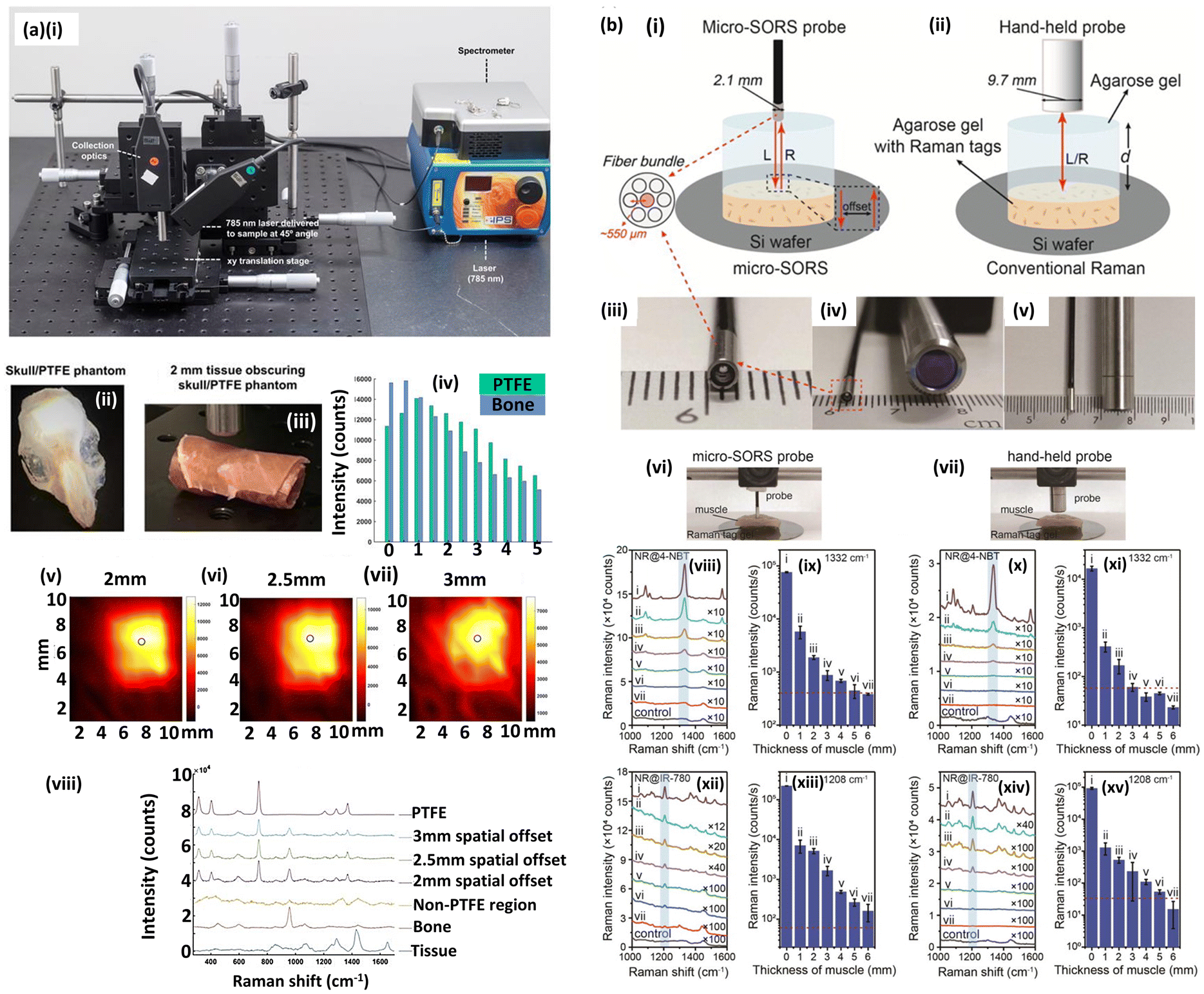 | ||
| Fig. 2 Applications of spatially offset Raman spectroscopy. (a) SORS for brain tumour detection. (i) SORS setup. A 785 nm laser delivered at a 45° angle with regards to the collection optics. Translational xyz stage used to move the laser away from the point of collection in order to apply the SORS technique. (ii) Skull/PTFE phantom. Polytetrafluoroethylene (PTFE) was glued underneath a mouse skull to keep it in place. The skull was then filled with agarose gel (1%) to create a brain tumor phantom. (iii) Skull/PTFE phantom wrapped in 2 mm of tissue to create a phantom for the imaging of glioblastoma multiforme (GBM) through the skull. (iv) Peak intensities of PTFE (739 cm−1) in comparison to bone (957 cm−1) at varying spatial offsets (0–5 mm). As the spatial offset increases, the contribution of both bone and tissue to the acquired spectra decreases. Further, as spatial offset increases, the contribution of PTFE to the spectrum increases. (v-vii) SORS false colour 2D heat maps of the peak intensity at 739 cm−1 through 2 mm of tissue and the skull at spatial offsets of (v) 2 mm, (vi) 2.5 mm and (vii) 3 mm. Measurements were carried out by moving an xy translational stage in steps of 1 mm to create an image of 10 × 11 pixels. The 2D heat maps show the detection of the PTFE square which was glued underneath the skull. Each circle on the heat map refers to the area of maximum intensity generated at 739 cm−1. (viii) Corresponding spectra collected at the point of maximum intensity at spatial offsets of 2, 2.5 and 3 mm are shown. A spectrum collected in a region where PTFE is not present is also shown and displays similar characteristics to that of tissue. This spectrum is representative for all spectra collected where the PTFE was not present. The bone and tissue reference spectra are displayed at the bottom of the stacked graph. A reference spectrum for PTFE is displayed at the top. All measurements were performed using a 785 nm laser, 2 s integration time, 5 acquisitions. Reprinted with permission from Nicolson et al. © Ivyspring International Publishing 2018. CC-BY-4.0. (b) Micro-SORS device. Measurement with (i) micro-SORS with an integrated fibre-bundle probe and (ii) conventional backscattering Raman spectroscopy with a hand-held probe. The micro-SORS probe consists of seven optical fibres with the centre one (red) for the excitation and the other six for the collection. Legend: L: incident light, R: Raman light. Photos of (iii) micro-SORS probe, (iv) the cross-section and (v) side views of (left) micro-SORS probe and (right) hand-held probe. Both devices set-up for measurement in (vi, vii). Limit of detection of aqueous Raman nanotags. (viii, x) Concentration-dependent SERS spectra of NR@4-NBT and (ix, xi) the Raman intensity 1332 cm−1 band, by (viii, ix) 785 nm and (x, xi) 532 nm laser. (xi–xv) Same but for NR@IR-780 molecule and Raman 1208 cm−1 band. The laser powers of 532 nm and 785 nm are 45 mW and 29.8 mW, respectively. Reprinted with permission from Zhang et al. © World Scientific 2021. CC-BY-4.0. | ||
An emerging area of interest in pathology research is that of virtual staining where AI may be used to replace conventional dye e.g. haematoxylin and eosin (H&E) staining, in highlighting clinically relevant tissue types in tomographically sliced micron-order thick tissue samples, augmenting consultant input and shortening the time to diagnosis. This can be facilitated with optical methods, including Raman spectroscopy and SORS, which affords the high analytical specificity to tell between similar molecular subtypes. Keller et al. (2011) used a SORS set-up with four sets of detector arrays showing 100% positive predictive value (PPV) for determination of breast cancer tumour margins in freeze-thawed specimens.69 In this context, the interaction of Raman photons in different kinds of turbid media is important to understand, and has been parameterised and simulated by Monte Carlo methods.70
4. Extending the spectral range: THz Raman and long Raman shift
One of the curious aspects of Raman spectroscopy is that the Raman peaks (bands), are measured relative to the laser wavelength, and typically in wavenumbers (measured in inverse centimetres, cm−1). This obscures the wavelength (in nanometres) at which the Raman peaks occur, and can, lead to miscalculation of the sensitivity of the longest shifted Raman bands. The quantum efficiency (QE) – a measure of incident electrons converted into measurable signal – of most silicon detectors falls off precipitously beyond 800 nm. For instance, at 780 nm laser excitation, the 613 cm−1 and 1650 cm−1 Raman bands of popular Raman dye Rhodamine 6G correspond to de-excitation wavelengths at 819 nm and 895 nm respectively (see ESI: Fig. S2†). Thus, if the detector is fixed as a silicon-based detector rather than one suitable for longer wavelengths i.e. InGaAs, then shorter wavelength laser excitation or at higher power may be required for the necessary measurement sensitivity. We note, within Si-based detectors, there is large variation in QE performance in the near infrared range.71 Banbury et al., in Raman fundoscopic measurements on the eye, found that a distant 2900 cm−1 peak, associated with the methylene (CH2) overtone Raman transition, to be easily detectable at 633 nm excitation with an Si detector. We note that thinking about the sensitivity range of detectors is also relevant for Raman metrology. This concerns the comparison, for standardisation's sake, of different Raman instruments, which may have different laser wavelengths and associated component responses e.g. spectrometer blaze (optimum diffracting wavelength).Similar thoughts may be needed in the small-shifted Raman regime i.e. with Raman bands close to the laser wavelength, often termed terahertz (THz) Raman (∼0.1–10 THz; 0–200 cm−1), which can be useful for studying structural properties of materials. For instance, in studies on hybrid perovskites, pertinent to solar cells, and further within investigations in shear (in-plane) and breathing (out-of-plane) excitations in 2D materials, useful in nano-scale electronic design.72 Within pharmaceuticals, THz, or ‘low-frequency’, Raman has displayed the ability to distinguish between polymorphs73–75 and benefit over conventional Raman spectroscopy for mixing monitoring of ingredients.76 Historically, these studies have been difficult to perform but extremely narrow laser line filters have now made THz Raman accessible. However, the excitation laser line (Rayleigh) cut-off filter clearly has some spectral width and thus a longer laser wavelength, with greater spread of Raman bands per unit wavelength, will permit the retention of more Raman features (see Fig. S2†). Following this, the Raman spectroscopist's focus might shift instead to the resolution of their system detector. The region within 10 cm−1 s spectral proximity of the laser Rayleigh line filter can be busy, packed with features, where many Raman bands overlap and can be difficult to distinguish from one another. This is uncharacteristic of Raman peaks in the fingerprint regime (∼400 cm−1–2000 cm−1) where peaks are normally narrow and separated, at least for simple matrices, unlike the inherently broad peaks associated with fluorescent emission.
5. Fluorescence rejection
The phenomenon of fluorescence often occurs alongside that of Raman scattering and is a spectroscopic technique in its own right.77 With respect to the Raman effect, fluorescence produces comparatively broad spectral features but with a large signal. It is thus a complementary technique to Raman spectroscopy offering more sensitive but less specific analytical detection. However, when both processes occur simultaneously, the larger inherent sensitivity i.e. cross-section, of the fluorescence phenomenon can swamp the Raman signal, even in resonance Raman78 or surface enhanced Raman spectroscopy,79 and has led to time-gating or fluorescence quenching approaches. Or more commonly, the development of post-processing algorithms in Raman spectroscopy to remove the fluorescence background signal, albeit the exact procedure followed in the fluorescence rejection literature is not always clear.80 However, another solution is to choose a laser wavelength where fluorescence is less prominent, and for portable Raman systems away from the laboratory environment, simply picking an excitation wavelength that minimises background fluorescent signal is the optimal strategy.81 The avoidance of fluorescence also led to use of 1064 nm excitation in Fourier-transform Raman systems (FT-Raman), arising first in the 1980s,54 which employ an interferometry set-up and also carry the benefit of better signal-to-noise, critical for the detection of subtle spectral differences.12 One group, for instance, with a focus on detecting structural Raman bands associated with cellulose and lignocellulose materials, found 1064 nm excitation to be ‘significantly more useful’ than conventional Raman with these materials owing to fluorescence mitigation.71 1064 nm Raman set-ups, although now uncommon, have appeared in newer hand-held and modular Raman spectroscopy systems.12An alternative option to remove sample fluorescence is to use sequentially shifted excitation (SSE) (Fig. 3). SSE uses a slight temperature change to remove the fluorescence background.53,82 While the thermal discrepancy alters the position of the Raman peaks, the spectral position of the fluorescent response does not change and thus can be subtracted.78 In a seminal study, Cooper et al. (2013) recorded the Raman spectra of dimethyl glyoxime, employed in Pd-refining metal complex formation, at four temperatures (20, 23, 26, 29 °C) to successfully subtract sample fluorescence by inducing Raman shifts (c. 1.2 cm−1 per °C). Fig. 3 displays recent examples of SSE usage, first, in historical artwork pigments (Fig. 3(a)).83 While the application of a portable SSE device outperforms that from a conventional benchtop dispersive Raman system, the authors note some limitations. For darker pigments, as in Fig. 3(a)(v–vii), broader Raman bands may be removed alongside the fluorescence background. Moreover, artefactual peaks can appear after SSE algorithm application. The authors note that should low wavenumbers be required, a conventional Raman system may be a better choice. Analogously, Culka and Jehlička have analysed minerals and gemstones with SSE and normal Raman spectroscopy (Fig. 3(b)).81,84 In the latter study on cut gems, they observe that aside from artefacts for some precious stones with specific fluorescence background profiles e.g. apatites, SSE performed admirably at fluorescence removal. In the case for some gemstones e.g. emerald, SSE was found to be much needed – the standard Raman spectrum displayed a large fluorescence background such that the Raman peaks were barely visible,84 a reminder that the optimal laser wavelength chosen alongside Raman instrumentation/set-ups can be highly sample-specific.
 | ||
| Fig. 3 Sequentially shifted excitation (SSE) and shifted-excitation Raman difference spectroscopy (SERDS) for background fluorescence removal/rejection. (a) SSE Raman spectrum of historical art pigments. (i) Portable sequentially shifted Raman device during measurement of artwork pigment inside a glass vial placed in the laser beam. Background: pigments in a historical case (further details of sample origin is in Innocenti et al. (2022)). (a)(ii–viii) Portable SSE (black line) and normal dispersive (red line) Raman spectroscopy of examined (ii–iv) violet pigments: (ii) blue pigment and calcite, (iii) triarylmethane pigment, (iv) crystal violet; (v–vii) black (carbon black) materials. The considered spectral range is 170–1800 cm−1. # Indicates the bands assigned to calcite. * Indicates contribution of glass. Reprinted with permission from Innocenti et al. © MDPI 2022 CC-BY-4.0. (b) SSE Raman spectra of precious stones. (i) Photographs of analysed cut gemstones and minerals (#1–#34). The scale of white lines is 5 mm. (ii–xi) Comparison of spectra recorded with a portable SSE Raman device (black lines) and spectra recorded with a bench-top Raman micro-spectrometer using 785 nm excitation (grey lines). For danburite (viii) and fluorite (xi) examples of raw spectra from the portable SSE Raman device are also given (light grey). Reprinted with permission from Culka and Jehlička John Wiley & Sons 2019. (c) SERDS Raman for bacteria species identification Raman mean spectra: shifted excitation Raman difference spectroscopy (SERDS) spectra after reconstruction with (i) non-negative least squares (NNLS), with (ii) NNLS and sensitive nonlinear iterative peak (SNIP); (iii) difference spectra of SERDS spectra (iii); (iv) conventional Raman spectra with SNIP background correction. E. aerogenes, Enterobacter aerogenes; E. faecalis, Enterococcus faecalis; P. aeruginosa, Pseudomonas aeruginosa; S. aureus, Staphylococcus aureus © Reprinted with permission from Lorenz et al. John Wiley & Sons 2019. | ||
6. Wavelength selection for specific samples
Raman spectroscopy has a wide range of applications, and concomitantly a wide range of sample materials and forms. From archaeological testing through to materials science, the range of samples is numerous, therefore the best laser pairing is essential for limiting laser damage and maximising Raman signal (Table 1). In general, lower photon energy lasers (longer wavelength) are used for biological samples that typically require less laser power therefore mitigating sample burning and fluorescence. UV Raman lasers tend to be used to probe materials such as graphene or diamond-like carbon coatings as this wavelength exhibits unique Raman peaks coming directly from SP2 and SP3 carbon bonds. This is important for insights into material defects and understanding resulting physical properties such as hardness. UV wavelengths, as seen with 257 nm,85 enhance these signals due to resonance effects that are observed for materials such as polycrystalline diamond films. To achieve such low wavelengths, frequency doubling of the 532 nm laser is required. At the other end of the spectrum, near-infrared (NIR) or IR lasers are observed in literature where sample degradation is to be avoided. An example of specific sample requirements is in the use of eye-safe lasers for probing traumatic brain injury.86 Here, IR-range wavelengths, 830 nm or even at 1400–1800 nm (ref. 87) can be used as the latter is generally considered safe due to the laser being less likely to damage the retina. The cornea absorbs prohibitively high from 3000 nm onwards (water bands).| Field | Material | Wavelengths (nm) | Comments |
|---|---|---|---|
| Art and archaeology | Pigments | 266 | UV excitation may be useful if the experiment involves capturing fluorescence spectroscopy data simultaneously |
| 355 | |||
| 532 | Longer wavelengths tend to suppress fluorescence where it is not desired | ||
| Dyes | 785 | If fluorescence background is to be suppressed for large samples, then 785 nm is a suitable option due to laser availability while providing reasonable signal strength | |
| Construction materials | |||
| Biological & biomedical | Cells | 514, 532, 633, 785, 830, 1064 | Higher photon energies (shorter wavelengths) may cause desirable changes in components that help reveal differences between a control. For these types of studies, optical tweezers using a combination of these wavelengths are typically used |
| Extracellular vesicles | |||
| Tissues | 514, 532, 633, 785, 830 | Anything lower than 514 nm in wavelength may have significant mutation or similar effects in biological matter. For more molecular studies, then the sub-633 nm options can provide better signal | |
| RNA | |||
| DNA | |||
| Proteins | |||
| Biomarkers | |||
| Biofluids | |||
| Drugs | |||
| Chemical analysis | Chemical compounds | 455, 514, 532, 633, 785, 1064 | For small particle studies, such as microplastics, then multiple wavelengths are typically used. Such as 532 nm and 785 nm and/or 1064 nm options, in an optical tweezer mode. However, for normal microscopy modes, 514–532 nm are found to work well for non-biological particles |
| Catalysts | |||
| Polymers | |||
| Environmental science | Rock and soils | ||
| Aquatic & atmospheric pollutants | |||
| Microplastics | |||
| Forensic science | Drugs | ||
| Explosives | |||
| Paints | |||
| Fibres | |||
| Food | |||
| Biological samples | |||
| Materials science | Graphene | 257, 514, 532, 785 | UV excitation opens greater insights into the carbon bonding in these types of samples. Such as determining SP2 and SP3 carbon content to better understand mechanical properties |
| Diamond-like carbon | |||
| Nanomaterials | 455, 514, 532, 633, 785 | 455–532 nm are found in many silicon and metal oxide studies that try to understand their crystalline states. For these types of samples, fluorescence is not as significant an issue, so while there are some groups who use 633–785 nm options, the former range provide better signal | |
| Semiconductors | |||
| Transition metal oxides |
Fig. 4 illustrates the recommended wavelengths for the types of samples to be measured, chiefly based on common issues such as best matching known resonances in the materials and minimising fluorescence. In certain applications this approach may not be appropriate due to specific sample needs. Fig. 4 also introduces metal choice for surface enhanced Raman spectroscopy (SERS) studies (discussed fully in section 7). Here, the approximate ranges commonly used for gold (Au) and silver (Ag) SERS media are given. We note that the range at which these metals are useful as plasmonic enhancers are actually significantly broader, judged by SERS figure of merits given elsewhere.79
 | ||
| Fig. 4 Recommendation of wavelengths with respect to the desired sample types. Images reprinted with permission under CC-BY-4.0, details in ESI.† | ||
Forensic & archaeological samples
Samples studied in these scenarios tend to be delicate and cannot afford destructive testing. Therefore, the use of high energy lasers is generally avoided. As such, when investigating such samples NIR wavelengths are typically selected. Authors have noted such applications of 785 nm in testing the nitrogen-based compounds in construction materials, leading to better understanding of possible degradation pathways for cultural heritage materials.88 Other applications observed include analysing dyes in ancient textiles.89 This example is a use-case where the sampling is done with SERS (see section 7). Therefore, other considerations such as the plasmonic tuning needed to be considered. Despite the fluorescence quenching effects of metals used in SERS, coupled with a 785 nm laser, the Raman signal still had issues with high fluorescence backgrounds in certain samples such as red dye safflower. An alternative to the fluorescence issues seen more commonly in biological samples is the application of a lower photon energy excitation source. 1064 nm excitation is commonly used in Fourier-transform Raman microscopy systems, such as in the study of elephant ivory-based objects with Raman spectroscopy.90 Another study looked at hair treated with cosmetics, again with 1064 nm excitation in a FT-Raman configuration.91In the case where more destructive testing of such samples is permitted, such as the identification of pigments and dyes in cultural heritage materials, then wavelengths in the UV region can be used to probe certain bonds that would otherwise be less pronounced at higher wavelengths.89 UV Raman spectroscopy allows users to probe differences in SP2 and SP3 bonded carbon which is of significant importance to more material sciences. UV sources are, however, comparatively rare and 532 nm remains a popular choice in carbonaceous research.55
Biological and biomedical samples
These types of samples typically can be categorised as: tissue (for example; bone,92 skin93 & colon94), fluids (e.g. urine,95 blood96 & saliva97), cells (e.g. bacteria98), proteins,99 small molecules (e.g. glucose100) and extra-cellular vesicles.101–103 While 785 nm lasers are often used for these applications, 633 nm is another viable option for biological analysis with often low fluorescence than other shorter wavelength lasers. However, as the scattering intensity is proportional to the inverse fourth power of the wavelength, 633 nm excitation brings significantly higher signal than 785 nm sources. The laser power needs to be carefully considered as too high a power will burn samples, whether 633 nm or 785 nm excitation, that can lead to graphitic peaks to occur in the spectra. This is less an issue if the sample is in water or is aqueous and therefore has some avenue to dissipate heat from the localised area. If fluorescence is still an issue even at 830 nm and 785 nm, then FT-Raman spectroscopy with 1064 nm is another method to minimise fluorescence. In addition to the minimised fluorescence background, FT-Raman is more suited to larger sample imaging while not as spatially resolved as dispersive alternatives. In addition to the wavelength selection, some attention is given to the polarisation of the excitation source, as in some studies it can reveal important structural information that can complement other observations.104Samples for optical trapping Raman spectroscopy
Optical traps are often used in bio-studies in Raman microscopy to manipulate small particles but also improve signal by about an order of magnitude. Particles such as microplastics,105 bacteria,106,107 and red blood cells.108 In biological studies, 532 nm and 514 nm lasers are sometimes reported in literature, however, this can risk higher fluorescence in the results, which would require significant background reduction, to observe the Raman peaks appropriately. Interestingly, for the examples given, the wavelength selections varies from 780 nm, 808 nm and 532 nm respectively. It was noted that the use of 532 nm excitation contributed to the spontaneous photoreduction of intracellular haemoglobin, which was used to determine the permanence of the oxidation of haemoglobin in hyperglycaemia-exposed red blood cells. The trapping effect is generally achieved with a focused Gaussian beam to trap a particle and is not limited to 514–532 nm and 785 nm lasers but also 1064 nm sources are typically used for this application.For samples that require a more advanced form of this Raman spectroscopy technique, where resonance Raman scattering is required, then the combination of the 514 nm and 785 nm lasers are utilised for optical trapping and resonance Raman measurements.109–111 While optical trapping is a useful strategy in the single or few-molecule limit, the experimental set-up is cumbersome and thus more amenable to fundamental research than practical implementation and commercial adoption. Another strategy is in the use of nanostructures for plasmonic enhancement in the form of surface enhanced Raman spectroscopy.
7. Surface enhanced Raman scattering/spectroscopy
Surface enhanced Raman spectroscopy (SERS) is technique whereby Raman signals can be increased by many orders of magnitude and even to single molecule detection. The effect was first noticed by Fleischmann and colleagues at roughened silver electrodes in the 1970s and later explained, chiefly, by the excitation of collective electron oscillations at the metal surface – plasmons, a quasi-particle of the free electrons, or more accurately in the case of SERS, a hybridised light-electron mode, a surface plasmon-polariton.79,112,113 Contingent on overlap with the spectral position of plasmon resonance, incident photons are increased in intensity via coupling to the intense local electric fields generated by plasmon-supporting nanostructures. This effect may also occur after interaction with the molecule i.e. post-Raman scattering, again depending on the spectral overlap of the (now Raman-shifted) photons’ wavelength with that of the plasmon resonance wavelength.114 After the initial electrochemistry investigations of the 70s, subsequent focus fell on the development of monodisperse nanoparticles, typically gold or silver, for SERS use, including more recently, those encapsulated in inert shells.115 Most recently, spurred by advances in lithographic techniques,116 a wide range of SERS-active substrates can now be produced and used for analytical purposes (Fig. 5), which can be characterised, for example, with atomic force microscopy and ellipsometry,49 scanning electron microscopy,117,118 transmission electron microscopy,118 and white light spectroscopy combined with electromagnetic modelling,119 amongst many others.114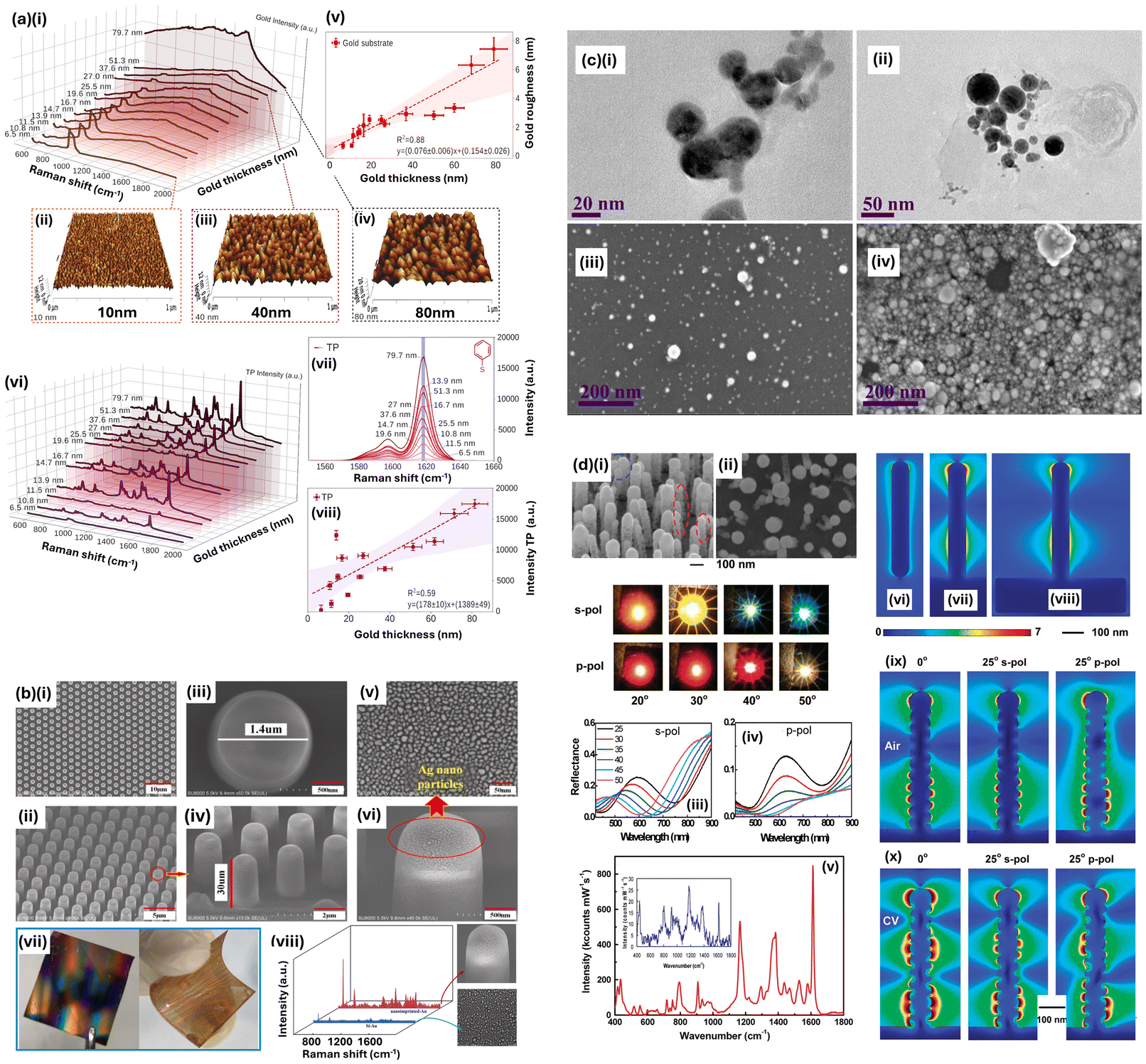 | ||
| Fig. 5 Classes of surface enhanced Raman-active media. (a) Granular surfaces (i) Waterfall spectra of background signal of granular gold surfaces as a function of increasing thickness (633 nm laser excitation). 3D atomic force microscopy (AFM) height images of gold-coated silicon substrates with a thickness of (ii) 10 nm, (iii) 40 nm, and (iv) 80 nm. (v) Roughness vs. gold thickness acquired from AFM measurements. (vi) Waterfall Raman/SERS spectra of 0.1 mM thiophenol (TP) over gold substrates with a range of thicknesses (633 nm laser). (vii) Representative SERS spectra of the 1600 cm−1 peak of TP as a function of the increasing gold thickness, resulting in a positive linear relationship between the thickness and the acquired SERS signal (in viii). Reprinted with permission from de Carvalho Gomes et al. © American Chemical Society 2022 CC-BY-4.0. (b) Top-down fabricated nanostructures. Scanning electron microscope (SEM) images of ordered SERS substrates fabricated by nanoimprint lithography (NIL). (i), (iii) and (v) are the top view of metal nanoparticles. deposited substrates with different magnification; (ii), (iv) and (vi) are profile views of SEM images, respectively. (vii) is the highly ordered metal nanomaterials deposited on hard Si (left) and flexible polydimethylsiloxane (PDMS) substrates (right). And (viii) is the SERS spectra for metal nanoparticles deposited on a nano-imprinted substrate (red spectrum) and a flat substrate (blue spectrum), respectively. 532 nm laser wavelength is used. The laser power is 0.5 mW and integration time is 1 s. Reprinted with permission from Cai et al. © Elsevier 2021. (c) Nanoparticles for SERS. Multiwavelength SERS of magnetoplasmonic nanoparticles obtained by combined laser ablation and solvothermal methods. (i, ii) Transmission electron microscopy and (iii, iv) scanning electron microscopy images of plasmonic nanoparticles obtained from (i, iii) Ag80Au20 and (ii, iv) Ag50Au50 targets. Laser ablation was performed in KCl concentration of 1 mM (Petri dish with 40 ml). Reprinted with permission from Talaikis et al. © American Chemical Society 2023 CC-BY-4.0. (d) Bottom-up fabricated nanopillars. SEM, optical, and Raman data for a sample comprising a random array of vertically aligned multi-walled nanotubes (MWNTs) coated with Ag. SEM images taken at (i) 45° and (ii) normal incidence. Features enclosed by red and blue dashed lines in (i) highlight posts where metal coverage appears to be more granular (red dash) and where pillar tops are leaning together (blue dash). Photographic insert: specular reflection from sample illuminated by beam of collimated, s-(p-)polarised white light at angles of incidence indicated, captured on standard digital camera. Reflectance spectra for (iii) s-polarised and (iv) p-polarised light at angles of incidence indicated in the key in (iii). (v) Raman spectrum from crystal violet (CV) deposited on Ag-surface of sample taken with Raman microscope using input laser of wavelength 632.8 nm and power 0.02 mW. Spectral intensity has been normalised to k-counts mW−1 s−1. (Inset in (v)) Calibration spectrum recorded from drop of CV of 10−3 M concentration deposited on Ag thin film. (vi, vii, viii) Plots of electric field intensity, calculated using finite element method, due to illumination of model systems comprising smooth Ag posts with length = 525 nm and diameter = 82 nm. Light of wavelength 632.8 nm is incident at 0°, that is, along the direction of the nanopost long axis with electric field polarised in the plane of incidence, which is also that of the cross sections: (vi) isolated Ag nanopost with hemispherical ends, (vii) Ag nanopost on semi-infinite Ag substrate, and (viii) Ag nanopost on finite Ag disk of diameter 600 nm and thickness 150 nm. (ix, x) Electric field intensity, calculated using a surface integral equation (SIE) technique, for nanoposts with granular Ag surface structure illuminated by light of wavelength 632.8 nm. length = 525 nm and diameter = 85 nm (to outermost edges of Ag coating) with Ag grains modelled as sections of sphere (polarisation and geometry as in (vi, vii, viii)). (ix) Granular nanopost comprised of pure Ag (i.e., no MWNT core) in ambient environment of refractive index = 1.0 (air). (x) Granular nanopost comprised of pure Ag in ambient environment of refractive index = 1.5, corresponding approximately to case of multilayer CV coverage. Reprinted with permission from Dawson et al. © American Chemical Society 2011. | ||
SERS is by now an expansive field in its own right,120 and has even birthed further sub-fields that can claim similar clout, such as studies with metallised scanning field microscopy tips in the form of tip-enhanced Raman spectroscopy (TERS) that provide plasmonic enhancement.121 We thus point to literature concerning SERS on enhancement factor calculations,122 analytical SERS,123–129 application to the biomedical field,37,130–132 including characterisation of SERS substrates with features on varying scales (‘analytical’ versus ‘hotspot-dominated’),114 and various theoretical aspects.79,133–136 We note a recent forward-looking review on the future of SERS authored by a range of eminent SERS scholars120 and a short retrospective casting an eye over what is, by now, 50 years of SERS research.137
As long as the spectral resonance position of simple plasmonic nanostructures is well-understood and may be easily tuned, for instance by modifying the diameter of gold or silver nanoparticle spheres, the plasmonic response of the geometry can be tailored to the laser wavelength(s) available. However, more bespoke geometries, for which the elucidation of the plasmonic response typically requires numerical modelling, may need a laser wavelength to match the structure, rather than the other way around. Plasmonic resonances for gold and silver nanostructures typically do not exceed 900 nm thus precluding the use of laser excitation at 1064 nm. To note, fluorescence can also be used as an enhanced modality – surface enhanced fluorescence138,139 – however the broad range of de-excitation wavelengths reduces the signal amplification from the typically spectrally narrow plasmonic resonances.
The plasmonic metal used is important to consider. The viability for plasmonic enhancement is often represented by a quality factor, which, while assuming different forms, is invariably a figure of merit incorporating the real part of the dielectric permittivity in the numerator and the imaginary part, accounting for absorbance, in the denominator.140 Silver performs well across the entire visible range as a plasmonic enhancer, and is cheaper than gold, but suffers from rapid oxidation, forming an oxide layer typically within hours, and exhibits toxicity, problematic if in vivo use is required.141,142 Gold is thus often optimal but the electronic (s → d shell) interband transitions below 600 nm in gold prohibit use of green lasers. Aluminium is the optimal choice in the UV, outperforming other metals below 300 nm and copper is a viable less expensive gold alternative, comparable to gold in terms of enhancement in the 600 nm–650 nm range, for example at the commonly employed 633 nm HeNe laser wavelength. Lithium, also performs admirably as a SERS-enhancing metal across the visible range, but is too reactive for widespread use. Iron has shown small yet useful enhancements in the context of gelatine detection, the thermal properties of which have been explored with nano-scale mapping via scanning thermal probe microscopy, in a modified atomic force microscopy arrangement.143 Palladium and platinum also show some favourable enhancing in the UV below 400 nm, but pale in comparison to aluminium above 300 nm.79 Some metals, silicon, for instance, with a low free electron density compared to the noble metals, has a large real part of its dielectric permittivity in the visible (and thus is useless for SERS in this regime), but can be used in the mid-infrared.144 Elsewhere research has been conducted in alternative plasmonic materials,140 composite materials, for example using ferromagnetics e.g. an iron underlayer, in bio-magnetoplasmonics to tune the plasmon resonance,145,146 or with foci in better fabrication practices for existing plasmonic metals,147,148 or those that are non-plasmonic in their enhancing i.e. chemical enhancement effects,149e.g. easily fabricable vanadium oxide150–153 or titanium nitride films.154
Analogous to laser wavelength choice for optimum plasmon excitation, excitation wavelength may be selected to target specific molecular bonds, functional groups or moieties in molecules in resonance Raman spectroscopy, which may also be combined with SERS for surface enhanced resonance Raman spectroscopy (SERRS). Here, the Raman transition is much more likely, corresponding to an electronic energy level and thus, a stronger Raman signal is observed.155
8. Multi-laser systems
Aside from considerations on molecular resonances, other specific experiments may require multiple laser wavelengths. For example, analogous to SSE, shifted-excitation Raman difference spectroscopy (SERDS) is a Raman technique that uses two or more different excitation wavelengths to mitigate fluorescence78,155 (Fig. 3(c)). A shift in the laser wavelength changes the spectral position of the Raman peaks but the fluorescence background profile does not similarly move (although changes in intensity may occur, for example due to photobleaching). Combined with spectral post-processing techniques, taking differentials then permits recovery of a fluorescence-free Raman spectrum. Grebrekidan (2016) explored SERDS with Raman measurements on a fluorescent dye in ethanol, porcine head tissue, and samples from the human oral cavity showing that larger wavelength shifts, of 1 nm (784 nm → 785 nm), were necessary to reconstruct undistorted Raman peaks from two laser wavelengths.80 Others have sought to improve SERDS with additional spectra: more lasers or a tuneable laser source.156,157 A disadvantage of the SERDS approach is the cumbersome reconstruction of the Raman spectra from the separate spectra generated from the multiple laser wavelengths, which can result in spectral artefacts.53We note, artefacts in spectra can be problematic in normal Raman spectra also. For instance, Lorenz et al. (2022) have investigated SERDS for bacteria identification using non-negative last squares (NNLS) with an optional sensitive-nonlinear-iterative-peak-clipping (SNIP) step for effective background removal,158 which was found to produce flatter final spectra, albeit with no additional (true) Raman peaks identified (Fig. 3(c)). Intuitively, the authors note that difference spectra, calculated from conventional Raman data and SERDS are not useful owing to the nature of SERDS, which has spectrally shifting Raman peaks (Fig. 3(c)(iii)). Curiously, the conventional Raman dataset, with SNIP background subtraction, performs best in a classification task (linear discriminant analysis, LDA) but the authors observe that this could be as a result of spectral artefacts. Contrariwise, the NNLS and NNLS-SNIP corrected datasets had no spectral artefacts apparent. In a spectroscopy context, we note that SNIP algorithms have been comprehensively discussed by Morháč and Matoušek (2008).159 Post-processing of Raman data has also been surveyed in ref. 160, alongside experimental measures to mitigate fluorescence in ref. 161, and in a biological samples context in ref. 162.
Elsewhere, Zhang (2021) et al. have proposed a two-laser portable confocal Raman spectrometer, with a nanostructure-based metalens to permit transmission at both laser wavelengths, 671 nm and 785 nm (5 nm full-width half-maximum; c. 92% transmission). This then allows interrogation of not only the fingerprint region 450–1750 cm−1 but also the high-wavenumber regime, 800–3800 cm−1, critical to the analysis of, for instance, melanomas.163 Subsequently, the same authors have proposed a fibre-optic addition with low-NA metamaterial lenses to focus both wavelengths to the same sample surface spot164 (see Fig. 8(c)).
Popularised by the late Richard Van Duyne and colleagues, multiple laser SERS studies, sometimes termed multiwavelength SERS or (wavelength-scanned) surface enhanced Raman excitation spectroscopy (WS-SERES or simply SERES), are enhanced Raman investigations using tuneable lasers or (often) custom-built multiwavelength Raman set-ups (Fig. 6). Thus, in conjunction with numerical modelling of nanoplasmonic systems, they give an assessment of how SERS sensors perform over a large range of excitation wavelengths.165 For example, in high-resolution transmission electron microscopy SERES studies, a discrepancy between the spectral position of the localised surface plasmon resonance (LSPR) and the maximum SERS enhancement factor (EF) was noted.166,167 Similar observations have been made for proximal nanopillars where the plasmonic gap modes are adjudged primarily responsible for the large SERS enhancements yet are of electromagnetic ‘near-field character’, displaying little or no signature in the far-field measurement i.e. reflectance spectra observed with a microscope168,169 (Fig. 6(a) and (b)). And notably, the Van Duyne group emphasised the electromagnetic enhancement in SERS, as opposed to chemical enhancing effects, by using SERES, in a seminal study. With a tuneable laser (610 nm–700 nm), they demonstrated overlap with the LSPR spectral range in de-excitation i.e. the wavelength of the photons post-interaction with the analyte molecule, clarifying that consideration of the Raman-shifted wavelength, in addition to the incident laser wavelength, was necessary for optimum SERS enhancement.170
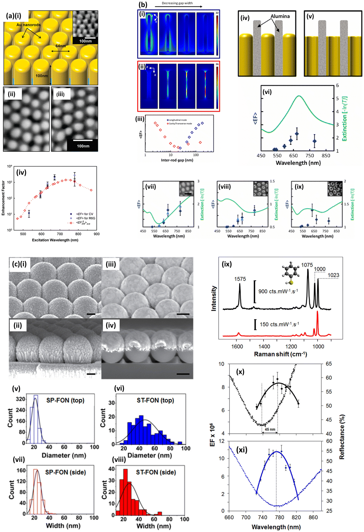 | ||
| Fig. 6 Multiwavelength Raman studies: wavelength-scanned surface enhanced Raman excitation spectroscopy. (a) SERS response of nanorod arrays as a function of wavelength. (i) Schematic of the model Au nanorod array after removal of a porous alumina (PAO) template. Inset shows an SEM image of the surface taken at 40° incidence. (ii, iii) SEM images of the nanorod substrate taken at normal incidence showing the quasi hexagonally ordered nature of the nanorod array. (iv) Graph comparing calculated (simulated) average enhancement factor (EF) for a Raman shift of 850 cm−1 and the observed experimental EF 〈EF〉 of Raman dyes CV and R6G at 915 and 775 cm−1, respectively. The calculated EF assumes a uniform distribution of gap widths in the range 1.5–20.0 nm. Reprinted with permission from Doherty et al. © American Chemical Society 2010. (b) Electromagnetic fields and EFs around nanorod arrays as the inter-rod gap is decreased. The effect on the longitudinal and the transverse or cavity resonances is shown. The nanorods shown in (i) are 250 nm long and 20 nm in diameter, with inter-rod gaps of 180, 100, 70, and 45 nm (at resonance wavelengths 960, 880, 800, and 650 nm, respectively). The nanorods shown in (ii) are 100 nm long and 50 nm in diameter, with inter-rod gaps of 16, 6, 4, and 3 nm (at resonance wavelengths 540, 594, 633, and 671 nm, respectively). E and k as marked indicate the polarisation and wave vector of the incident radiation. (iii) shows a plot of the calculated average enhancement factor on resonance (on a logarithmic scale) as a function of the inter-rod gap for the rods shown in (i) and (ii). Schematic illustrations of unetched gold (iV) nanorod and (v) nanotube arrays still encased in the alumina template. (vi–ix) Graphs comparing the measured EF and optical extinction [−ln(T)] at normal incidence for (vi) nanotubes still encased in the alumina template with average wall thickness of 10 nm and average diameter of 45 nm, (vii) nanorods with an average diameter of 48 nm and for (viii, ix) nanotubes with average wall thickness and diameter, respectively, of 12 nm and 45 nm and of 9 nm and 50 nm. In all four cases, the average array period was 65 nm. The nanorod or tube length was approximately 150 nm in (vi) and 100 nm in (vii, viii, ix). The green curves indicate the optical extinction of the samples. Black-diamond and blue-triangle data points indicate the EF of the 915 cm−1 band of CV and the 775 cm−1 band of R6G, respectively. Inset: SEM images of each sample. All SEM images are on the same scale (scale bar ¼ 100 nm). Reprinted with permission from Doherty et al. © American Physical Society 2013 CC-BY-3.0. (c) Studying the near- and far-electric fields with enhanced Raman spectroscopy of rough silver nanospheres. SEM images of metallised spun-film-over-nanospheres (SP-FONs) (i, ii) and metallised while stationary-film-over-nanospheres (ST-FONs) (ii, iv). Scale bars correspond to 200 nm (i, ii) and 300 nm (iii, iv). (v–viii) Size distributions of nanofeatures on the top (upper panels) and side (lower panels) surfaces of SP- and ST-FONs. (ix) SERS (black) and normal Raman (red) spectra of benzenethiol (BZT) acquired with 785 nm excitation, Power = 50 μW, and time = 10 s. (x, xi) Near-field profiles (EF, solid line) and far-field optical responses (reflectance, dotted line) of ST-FONs and SP-FONs. Tuneable laser 725–825 nm (10 nm increments). Reprinted with permission from Kurouski et al. © American Chemical Society 2018. | ||
The same group have also examined discrepancy in excitation wavelength for optimum SERS enhancement for dome-like nanostructures where surface texturing, contingent on metalisation conditions, played a key role171 (Fig. 6(c)). Thus, the laser wavelengths needed for a SERES study depends on the goal: for an assessment of how SERS media perform across the visible-NIR range, five or six reasonably spectrally spaced wavelengths would suffice; whereas for a precise determination of, say, SERS EF around one resonant peak highlighted by far-field optics, a few closely spaced wavelengths, or preferably a tuneable laser source, may be more appropriate.
SERES can be used as an initial selection tool for optimum laser wavelength to achieve resonant Raman for a molecule of interest or elucidate optimum enhancement from a plasmonic substrate. In this way SERES can augment theoretical methods – computational chemistry e.g. density functional theory, and electromagnetic nanostructure simulations e.g. the finite element method or finite-difference time-domain (FDTD) method, in research studies. Recently, Le Ru and Auguié (2024) have suggested multiwavelength Raman studies should be used to check Raman analytes for their suitability to be used as standards, discussing resonance shifts for common Raman dyes Crystal Violet and Rhodamine 6G when they adsorb to a metal surface.172 Further, we observe that the SERES approach could be used in a data fusion context where different Raman spectral datasets, acquired with different laser wavelengths, are combined (concatenated) in some fashion to improve diagnostic accuracy.
The nature of SERES studies naturally gives rise to the use of unusual laser wavelengths in Raman spectroscopy with the goal to get a good coverage of the spectral range. Uncommon laser excitations can also arise however in specific experiments (Fig. 7), for illustration, 239 nm (UV laser),56 473 nm (blue laser),173 and 830 nm (near-infrared laser),174 in studies on cocaine detection, cystic fibrosis biomarker (thiocyanate) identification, and traumatic brain injury biomarkers, respectively.
 | ||
| Fig. 7 Uncommon Raman excitation wavelengths. (a) Raman spectroscopy for brain injury biomarker assessment. Characteristic Raman spectra fingerprints of acute-phase traumatic brain injury (TBI) biomarkers, acquired at excitation wavelengths of 514 nm (green line), 633 nm (red line), 785 nm (blue line), and 830 nm (yellow line). (i) N-Acetyl-L-aspartic acid (NAA); (ii) glutathione (GSH); (iii) glial fibrillary acidic protein (GFAP). While 514, 633 and 785 nm are common Raman wavelengths, 830 nm is a less common choice. Reprinted with permission from Harris et al. © MDPI 2023 CC-BY-4.0. (b) Raman spectroscopy for illicit drug detection in saliva. Resonance Raman spectra of 1 mg mL−1 cocaine (COC) in acetonitrile (ACN), 1 mg mL−1 COC in water, 100 μg mL−1 COC in oral fluid, pure oral fluid, and the difference spectrum between those of COC in oral fluid and the pure oral fluid. Excitation wavelength was 239 nm and excitation power was 10 mW. Reprinted with permission from D'Elia et al. © Elsevier 2018. (c) Raman spectroscopy for cystic fibrosis (CF) biomarker identification. Raman spectroscopy signature for thiocyanate (SCN−) provides an indicator of CFTR function. (i) A schematic showing the role of the cystic fibrosis transmembrane regulator (CFTR) in salivary SCN− secretion. The CFTR secretes both SCN− and Cl− into saliva. Once secreted, SCN− can be consumed into OSCN− either directly via salivary peroxidase (SPO) or by reacting with OCl−. Due to this and to the lower amount of SCN− transported through the channel, CF subjects have much lower SCN− saliva concentrations. (ii) The SCN− signature as seen with Raman spectroscopy. In CF patients, a Raman peak corresponding to SCN− at 2070–2080 cm−1 is almost absent. (iii) Comparison of SCN− Raman signals in dried saliva versus controls, including pure KSCN and KSCN dried from H2O, KOCN, and KCN. The thick black line is the Lorentzian fit for the saliva sample. Laser wavelengths used in this study are 473 nm (uncommon) and 633 nm (common). Reprinted with permission from Malkovskiy et al. © American Chemical Society 2018. | ||
9. Travelling light: portable Raman systems
A wide-range of kinds of laser systems are now available from large, lab-based, to carriable (say, <15 kg) systems, to portable handheld Raman devices of a kg or two (Fig. 8). Laser sizes have continued to shrink in line with smaller and smaller Raman spectrometer systems allowing pocket-sized miniaturisation in a far cry from the bulky dye laser boxes or even the smaller, but nevertheless impractical-to-transport, HeNe laser tubes ubiquitous in laser labs in the 80s and 90s. These developments have occurred alongside other efforts in downscaling, including microfluidics,42 in a lab-on-chip/point-of-care context,175–178 and within smartphone-based sensors.179–181 Miniature Raman systems typically require small diode lasers based on semiconductor technology and that can be easily integrated in microelectronics. Unfortunately, in addition to the need for optical isolation, for example with a Faraday rotator, diode lasers often suffer from frequency drift, power instability, and mode hopping, and thus may need a routine calibration.182 | ||
| Fig. 8 Types of Raman systems. (a) Analysis of commercial systems used in novel biofluid study meta-analysis of the Raman-saliva literature. (i) Laser wavelengths and (right) application breakdown. (ii) Raman systems employed: vendors and popular models. Reprinted with permission from Hardy et al. © Taylor and Francis 2022 CC-BY-4.0. (b) Portable Raman device for neurodiagnostic ocular measurements. The engineered EyeD system overview. (i) Convergence of a collimated beam entering the eye onto the retina (left) and the defocusing compound lens effect (right) resulting from the introduction of a microscope objective. The use of an additional lens is thus detrimental for measurement. (ii) Representative Raman spectra of murine brain tissue in the fingerprint and high-wavenumber regions, measured using a commercial In-Via Raman system, with an excitation laser of 633 nm (0.39 to 0.63 mW). Comparison with 785 nm spectra (black dash), showing an enhanced response at high wavenumbers (green highlight). (iii) Photograph of the bench-top breadboard setup, including smartphone, housing, and input/output fibers. (iv) 3D schematics of the combined fundus photography and eye-safe Raman spectroscopy optical paths contained within a 3D-printed housing. a.u., arbitrary units. Reprinted with permission from Banbury et al. © AAAS 2023 CC-BY-4.0. (c) Simulated Raman probe design with metalens for multi-wavelength analyses. (i) Overview design of Raman probe and potential applications. (ii) Focal point profiles of all metalenses. 3D beam propagations of all three metalenses – magenta: 785 nm hybrid off-axis metalens, blue: 810–910 nm achromatic on-axis metalens, green: 671 nm hybrid off-axis metalens. The focal plane is shown in black outline. (iii) Perspective view of the overlapping region of all three metalenses. (iv) Normalised intensity plots of focal points along the x, y, and z-axis, showing the measurements of focal points in each direction. Reprinted with permission from Zhang et al. © Frontiers Media SA 2022 CC-BY-4.0. | ||
Portable Raman systems, defined as ∼10 kg carriable systems and even smaller genuinely handheld devices, dictate limitations of components employed. For instance, a smaller footprint prescribes a more dispersive diffraction element to account for a shorter path length to the detector. In Raman spectroscopy, preferably a ruled diffraction grating that is blazed i.e. optimally efficient, for the laser wavelength, to achieve optimal throughput. But the choice of laser might also be limited, indeed, the advent of small, high-power, less-expensive semiconductor lasers has fuelled progress into miniaturised Raman systems.183 Given that many compact Raman systems are for specific application areas,184 truncated spectral ranges can suffice. The exact span of the Raman fingerprint region required in nanometres is acutely dependent on the laser wavelength used (Fig. S2†). Thankfully, the performance of any laser, in conjunction with a specific spectrographic set-up can be modelled with high fidelity, prescribing the spectral range, resolution achievable (pm μm−1), on the detector, via study of an optical or modulation transfer function – (OTF/MTF), as well as any likely stray light.185,186 Finally, we note the emergence of ‘on-chip Raman’ devices,187 perhaps internet-of-things (IoT) –enabled, where a Raman system can be truly miniaturised for optimal applications in-the-field/point-of-care,188–191 which could revolutionise decentralised medicine, wearable optical technologies,192–194 and find use in low-resource settings.195 Here, vertical cavity emitting lasers (VCSELs) may be employed,196 allied with integrated metamaterial surfaces for beam manipulation,197 which can offer a compact solution with low beam divergences. However, the nature of the VCSEL material layers (distributed Bragg reflector layers), thickness, composition, amenable to fabrication influence the wavelengths achievable.198
10. When in Rome do as the Ramans do!
General points and emerging trends in Raman spectroscopy
With the biennial International Conference On Raman Spectroscopy meeting in 2024 in Italy (ICORS 2024) having passed, and the interaction of many leading Raman researchers, it is worth pointing out that, in many cases, Raman spectroscopists will use what they are provided with, where options in the green at 532 nm and bordering the near infrared at 785 nm are common with commercial systems,31,55 perhaps followed closely by 633 nm in the red region. Most Raman practitioners continue to use off-the-shelf systems for their ease of use and high throughput. As an indication of this, the kinds of systems used in the context of Raman and saliva, an emerging diagnostic biofluid, have been examined recently, with combined Renishaw and Horiba Jobin Yvon systems constituting half of all Raman systems used in the literature surveyed (n = 82) (Fig. 8(a)).31 Custom-built Raman systems permit more flexibility, for instance, one research group has employed an open-bench Raman system to investigate the plasmonic response of gold and silver nanostructures at seven different laser wavelengths from 532 nm to 780 nm.168,169 Tuneable wavelength lasers, allow a continuous range of laser wavelengths to be used, as long as appropriate bandpass, perhaps in the form of a linear variable filter, and edge (longpass) optical filters are available. We note the availability of supercontinuum lasers, which cover a much wider wavelength span, alongside, acousto-optical tuneable filters (AOTFs), but with linewidths typically too broad for Raman spectroscopy. The type of laser might also come into play, restricting wavelength used, for example, in time-resolved Raman or in the non-linear Raman technique, coherent anti-Stokes Raman spectroscopy (CARS), which can benefit from the reduced bandwidths associated with short nanosecond pulsed laser outputs.199 An alternative summary of key issues and thought process in Raman laser choice is given in AI-generated meta maps in Fig. S3.†Moreover, both commercial and home-built Raman systems might have other optical components having performance in optical wavelength ranges that may be non-negotiable depending on the specific experiment, for instance beamsplitters,169 which may be useful to ensure collection in the (180° reflection) so-called backscattering configuration, which is needed for some experimental–theoretical comparisons in SERS.79
Further, sometimes Raman spectroscopy may not be the only analytical modality employed, where two or more datasets from various methods are combined for optimal classification accuracy, analogous to ref. 77 where fluorescence, alongside UV-vis and short-wave infrared (SWIR) absorption spectroscopic datasets are combined. Or where Raman is used in conjunction with, i.e. before or after, other analysis types, for example surface plasmon resonance and SERS combined studies200 or as in the selective sampling of cancer tissue in ref. 64, which uses inherent tissue auto-fluorescence as an initial step to screen for regions of interest in the disease tissue sample before using Raman to hone in on likely spots of pathology. In such cases, or in otherwise complex experiments,201 Raman laser choice might be an afterthought.
We note a selection of research areas within Raman spectroscopy, which we have left untouched or comparatively so, but which have come to prominence recently, demonstrated by their presence at the recent ICORS conference.202 It is a very good question what impact AI will continue to have on Raman spectroscopy, including Raman laser choice (will sophisticated algorithms for post-processing of Raman spectra mean less emphasis is required on Raman instrument design?). Elsewhere a large emphasis was apparent on Raman metrology – how can we better meaningfully compare data from different Raman systems and measurements? This is a concern that dovetails with the increased development of handheld Raman devices, including fully integrated, palm-sized instruments. Such devices are sought for an array of application spheres, another expanding domain for Raman spectroscopy with many application-focused studies now apparent, including artwork, foodstuffs, and even geoscience and extra-terrestrial studies in space. Microplastics detection and analysis via Raman is perhaps a surprisingly new topic, given its relative prominence, and is indicative of growing concerns over environmental and human health issues and the potential of Raman spectroscopy to offer solutions.
Many previously popular areas still attract research vigour, including 2D materials research, fundamental/theoretical Raman and SERS works, including computational electromagnetic and computational chemistry approaches. Similarly, Raman imaging is still garnering significant attention, as does tip-enhanced Raman spectroscopy (TERS). All of these listed research domains in Raman spectroscopy, both those emerging and well-developed, will each have their own specific needs and thus requirements in terms of laser wavelength selection. Undoubtedly, then, there are many other considerations to think about in wavelength choice, linked to particular experiments and applications. For instance, since the writing of this article, in our own labs we have been thinking about sample temperature determination via Raman through calculation of the Stokes/Anti-Stokes Raman signal ratio. This measurement depends of the Boltzmann distribution, which encompasses the Raman shift frequency, ν, which is dependant on the wavelength of the laser excitation wavelength chosen (see Fig. S2†).
11. Conclusion
In this article we have identified some of the most important considerations in laser choice in Raman experiments. There are many decisions affecting laser choice that are much more general, such as stability, sensitivity to ambient temperature and humidity, operational lifetime and cost. Undoubtably, given the breadth of Raman research on offer, there are other niche considerations in specific Raman applications. However, most laser wavelengths will produce some useful spectral data regardless of the analyte or specific set-up. This is important to remember where labs engage in a disparate range of Raman experiments. Raman spectroscopy is a rapidly evolving area and technological developments, for instance, increasingly miniaturised Raman systems, could influence laser types and wavelengths chosen for use. The goal of this article has been to aid the Raman spectroscopist, where the luxury is afforded, to make an optimal decision. However, one might say that there are really only two critical mistakes you can make with lasers in Raman spectroscopy: one for each eye!203Author contributions
MH: all sections and figures bar below. HOMC: section 6 (wavelength selection for specific samples), Table 1 and Fig. 4. Manuscript review.Data availability
No primary research results, software or code have been included and no new data were generated or analysed as part of this review.Conflicts of interest
The authors declare no conflict of interest.Acknowledgements
UK Research and Innovation (UKRI), Strength in Places Fund (Smart Nano NI). This article arose from our investigations into portable Raman systems as part of the Smart Nano NI project at School of Maths and Physics, Queen's University Belfast. Thank you to the Smart Nano NI Consortium, specifically Causeway Sensors Ltd and Cirdan Imaging Ltd.MH – I am grateful to Dr Breandán J. F. Hill and Dr Robert J. Pollard, both Causeway Sensors Ltd for many useful spectroscopy conversations alongside Smart Nano NI Project Manager Dr Jason Wiggins for his guidance and support, and Smart Nano NI Project Lead, Professor Robert M. Bowman for his project leadership. I am also grateful to Dr Paul Dawson, Centre for Nanostructured Media, School of Maths and Physics, Queen's University Belfast, for getting me interested in Raman spectroscopy with lots of advice in the area along the way, and research group members Dr Matthew D. Doherty and Dr Ryan McCarron for many appreciated conversations. Similarly, I am grateful to Professor Pola Goldberg Oppenheimer, School of Chemical Engineering, University of Birmingham, for many valued interactions in Raman spectroscopy and from whom I learnt a lot regarding Raman applications.
References
- A. Smekal, Naturwissenschaften, 1923, 11, 873–875 Search PubMed.
- W. Dickson and W. Dickson, Christmas Lectures 2013, King's CollegeLondon, UK. 2013 Search PubMed.
- C. V. Raman and K. S. Krishnan, Nature, 1928, 121, 501–502 CrossRef CAS.
- D. A. Long, The Raman Effect: A Unified Treatment of the Theory of Raman Scattering by Molecules, John Wiley and Sons, London, 2002 Search PubMed.
- D. Martin, Sers and the rise of the Raman empire. Available from: https://www.chemistryworld.com/features/sers-and-the-rise-of-the-raman-empire/9264.article accessed: 11th Apr 2025.
- S. Lohumi, S. Lee, H. Lee and B. K. Cho, Trends Food Sci. Technol., 2015, 46, 85–98 CrossRef CAS.
- D. I. Ellis, V. L. Brewster, W. B. Dunn, J. W. Allwood, A. P. Golovanov and R. Goodacre, Chem. Soc. Rev., 2012, 41, 5706–5727 RSC.
- D. I. Ellis, H. Muhamadali, S. Haughey, C. Elliott and R. Goodacre, Anal. Methods, 2015, 7, 9401–9414 RSC.
- A. P. Craig, A. S. Franca and J. Irudayaraj, Annu. Rev. Food Sci. Technol., 2013, 4, 369–380 CrossRef CAS PubMed.
- L. M. Reid, C. P. O'Donnell and G. Downey, Trends Food Sci. Technol., 2006, 17, 344–353 CrossRef CAS.
- J. Zheng and L. He, Compr. Rev. Food Sci. Food Saf., 2014, 13, 317–328 CrossRef CAS PubMed.
- C. Rathmell , Photonics Spectra. Available from: https://www.photonics.com/Articles/Raman_Spectroscopy_Dishes_Up_Solutions_for_the/p5/a66859 accessed: 17th Mar 2025.
- E. Buchan, M. Hardy, P. de Carvalho Gomes, L. Kelleher, H. O. M. Chu and P. Goldberg Oppenheimer, Appl. Spectrosc. Rev., 2024, 59, 277–314 CrossRef.
- B. Yu, M. Ge, P. Li, Q. Xie and L. Yang, Talanta, 2019, 191, 1–10 CrossRef CAS PubMed.
- V. D'Elia, G. Montalvo García and C. García Ruiz, Appl. Spectrosc. Rev., 2015, 50, 775–796 CrossRef.
- F. Inscore, C. Shende, A. Sengupta, H. Huang and S. Farquharson, Appl. Spectrosc., 2011, 65, 1004–1008 CrossRef CAS PubMed.
- C. Andreou, M. R. Hoonejani, M. R. Barmi, M. Moskovits and C. D. Meinhart, ACS Nano, 2013, 7, 7157–7164 CrossRef CAS PubMed.
- S. Farquharson, C. Brouillette, W. Smith and C. Shende, Front. Chem., 2019, 7, 706 CrossRef CAS PubMed.
- K. Virkler and I. K. Lednev, Forensic Sci. Int., 2008, 181, 1–5 CrossRef PubMed.
- K. Virkler and I. K. Lednev, Forensic Sci. Int., 2009, 193, 56–62 CrossRef CAS PubMed.
- K. Virkler and I. K. Lednev, Forensic Sci. Int., 2009, 188, 1–17 CrossRef CAS PubMed.
- V. Sikirzhytski, A. Sikirzhytskaya and I. K. Lednev, Appl. Spectrosc., 2011, 65, 1223–1232 CrossRef CAS PubMed.
- A. Sikirzhytskaya, V. Sikirzhytski and I. K. Lednev, Forensic Sci. Int., 2012, 216, 44–48 CrossRef CAS PubMed.
- B. Vyas, L. Halamkova and I. K. Lednev, Forensic Chem., 2020, 20, 100247 CrossRef CAS.
- K. C. Doty, G. McLaughlin and I. K. Lednev, Anal. Bioanal. Chem., 2016, 408, 3993–4001 CrossRef CAS PubMed.
- M. Hardy, M. D. Doherty, I. Krstev, K. Maier, T. Möller, G. Müller and P. Dawson, Anal. Chem., 2014, 86, 9006–9012 CrossRef CAS PubMed.
- M. López-López and C. García-Ruiz, Trends Anal. Chem., 2014, 54, 36–44 CrossRef.
- A. Hakonen, P. O. Andersson, M. Stenbæk Schmidt, T. Rindzevicius and M. Käll, Anal. Chim. Acta, 2015, 893, 1–13 CrossRef CAS PubMed.
- Y. Huang, W. Liu, Z. Gong, W. Wu, M. Fan, D. Wang and A. G. Brolo, ACS Sens., 2020, 5, 2933–2939 CrossRef CAS PubMed.
- R. Waterbury, T. Conghuyentonnu, H. Hardy, A. Jacobson, T. Molner, R. Robins and M. Scott, in SPIE Defense + Commercial Sensing, Proceedings Volume 12541, Chemical, Biological, Radiological, Nuclear, and Explosives (CBRNE) Sensing XXIV, SPIE, Orlando, FL, USA, 2023, p. 1254108.
- M. Hardy, L. Kelleher, P. de Carvalho Gomes, E. Buchan, H. O. M. Chu and P. Goldberg Oppenheimer, Appl. Spectrosc. Rev., 2022, 57, 177–233 CrossRef.
- E. Buchan, L. Kelleher, M. Clancy and P. Goldberg Oppenheimer, Anal. Chim. Acta, 2021, 1185, 339074 CrossRef CAS PubMed.
- P. Meenapriya, Int. J. Oral Craniofac. Sci., 2016, 2, 11–14 CrossRef.
- L. Ma, Z. Zhang and X. Li, Appl. Spectrosc. Rev., 2020, 55, 197–219 CrossRef CAS.
- L. B. Leal, M. S. Nogueira, R. A. Canevari and L. F. C. S. Carvalho, Photodiagnosis Photodyn. Ther., 2018, 24, 237–244 CrossRef CAS PubMed.
- M. J. Baker, S. R. Hussain, L. Lovergne, V. Untereiner, C. Hughes, R. A. Lukaszewski, G. Thiéfin and G. D. Sockalingum, Chem. Soc. Rev., 2016, 45, 1803–1818 RSC.
- R. Goodacre, M. J. Baker, D. Graham, Z. D. Schultz, M. Diem, M. P. Marques, G. Cinque, R. Vernooij, J. Sulé-Suso, H. J. Byrne, K. Faulds, M. Hermes, H. Fleming, A. Bonifacio, R. Dluhy, P. Gardner, S. El-Mashtoly, B. Wood, K. Gough, S. Fornasaro, S. Kazarian, L. Jamieson, W. Petrich, G. D. Sockalingum, N. Stone, C. Kendall, F. Sinjab, P. Haris, A. Subaihi, S. Remiszewski, P. Hellwig, V. Sergo, K. Gerwert, C. Phillips and C. J. Campbell, Faraday Discuss., 2016, 187, 575–601 RSC.
- L. Wu, Z. Wang, S. Zong and Y. Cui, Biosens. Bioelectron., 2014, 62, 13–18 CrossRef CAS PubMed.
- X. Cui, T. Wei, M. Hao, Q. Qi, H. Wang and Z. Dai, J. Hazard. Mater., 2020, 391, 122217 CrossRef CAS PubMed.
- M. Song, I. M. Khan and Z. Wang, Food Anal. Methods, 2021, 4, 2136–2151 CrossRef.
- S. Yadav, M. A. Sadique, P. Ranjan, N. Kumar, A. Singhal, A. K. Srivastava and R. Khan, ACS Appl.Bio Mater., 2021, 4, 2974–2995 CrossRef CAS PubMed.
- R. Panneerselvam, H. Sadat, E. M. Höhn, A. Das, H. Noothalapati and D. Belder, Lab Chip, 2022, 22, 665–682 RSC.
- L. Chen and J. Choo, Electrophoresis, 2008, 29, 1815–1828 CrossRef CAS PubMed.
- N. Choi and S. Schlücker, ACS Nano, 2024, 18, 5998–6007 CrossRef CAS PubMed.
- M. Lu, Y. Joung, C. S. Jeon, S. Kim, D. Yong, H. Jang, S. H. Pyun, T. Kang and J. Choo, Nano Converg., 2022, 9, 39 CrossRef CAS PubMed.
- K. Kim, D. K. Han, N. Choi, S. H. Kim, Y. Joung, K. Kim, N. T. Ho, S. W. Joo and J. Choo, Anal. Chem., 2021, 93, 6673–6681 CrossRef CAS PubMed.
- Y. Joung, K. Kim, S. Lee, B. S. Chun, S. Lee, J. Hwang, S. Choi, T. Kang, M. K. Lee, L. Chen and J. Choo, ACS Sens., 2022, 7, 3470–3480 CrossRef CAS PubMed.
- L. Wang, X. Wang, L. Cheng, S. Ding, G. Wang, J. Choo and L. Chen, Biosens. Bioelectron., 2021, 189, 113360 CrossRef CAS PubMed.
- P. De Carvalho Gomes, M. Hardy, Y. Tagger, J. J. S. Rickard, P. Mendes and P. Goldberg Oppenheimer, J. Phys. Chem. C, 2022, 126, 13774–13784 CrossRef CAS PubMed.
- S. E. J. Bell and A. R. Boyd, Raman Spectroscopy – An Overview of its Application and Potential for Life Sciences, World Markets Research Centre Ltd [Research report (external)], London, 2002 Search PubMed.
- P. J. Hendra , available from: https://www.irdg.org/meetings/irdg-200-250/irdg-212/accessed: 11th Dec 2018.
- S. Perkowitz, Phys. World, 2010, 23, 16 CrossRef.
- J. Cooper, R. Jones, S. Marshal and K. Wise, Spectroscopy, 2014, 29, 24–28 Search PubMed.
- R. Crocombe, Spectroscopy, 2023, 38, 32–40 Search PubMed.
- A. Flack , Photonics Spectra. Available from: https://www.photonics.com/Articles/Part_by_Part_The_Anatomy_of_a_Raman_Microscope/a69685 accessed: 17th Mar 2025.
- V. D’Elia, G. Montalvo, C. Garcia Ruiz, V. V. Ermolenkov, Y. Ahmed and I. K. Lednev, Spectrochim. Acta, Part A, 2018, 188, 338–340 CrossRef PubMed.
- Edinburgh Instruments, How to Choose your Lasers for Raman Microscopy. Available from: https://www.edinst.com/blog/lasers-for-raman-spectroscopy/ accessed: 11th Apr 2025 Search PubMed.
- University of Birmingham Laser Safety Guidelines, University ofBirmingham, UK, 2020.
- G. Harris, J. J. S. Rickard, G. Butt, L. Kelleher, R. J. Blanch, J. Cooper and P. Goldberg Oppenheimer, IEEE Rev Biomed Eng., 2023, 16, 530 Search PubMed.
- C. Banbury, G. Harris, M. Clancy, R. J. Blanch, J. J. S. Rickard and P. Goldberg Oppenheimer, Sci. Adv., 2023, 9, adg5431 CrossRef PubMed.
- F. Adar, Spectroscopy, 2010, 25, 16–23 CAS.
- N. J. Everall, Analyst, 2010, 135, 2512–2522 RSC.
- M. G. Lizio, R. Boitor and I. Notingher, Analyst, 2021, 146, 3799–3809 RSC.
- M. G. Lizio, Z. Liao, D. W. Shipp, R. Boitor, R. Mihai, J. S. Sharp, M. Russell, H. Khout, E. A. Rakha and I. Notingher, Biomed. Opt. Express, 2021, 12, 940 CrossRef PubMed.
- Agilent, Vaya Handheld Raman Spectrometer for Raw Material Identification. Available from: https://www.agilent.com/en/product/molecular-spectroscopy/raman-spectroscopy/raman-pharmaceutical-analysis-systems/vaya-handheld-raman-spectrometer-for-raw-material-identification. Accessed: 11th Apr 2025 Search PubMed.
- F. Nicolson, L. E. Jamieson, K. Plakas, N. C. Shand, K. Faulds, S. Mabbott, M. R. Detty and D. Graham, Analyst, 2018, 143, 5965–5973 RSC.
- F. Nicolson, L. E. Jamieson, S. Mabbott, K. Plakas, N. C. Shand, M. R. Detty, D. Graham and K. Faulds, Chem. Sci., 2018, 9, 3788–3792 RSC.
- Y. Zhang, L. Lin, J. He and J. Ye, J. Innov. Opt. Health Sci., 2021, 14, 2141001 CrossRef CAS.
- M. D. Keller, E. Vargis, N. de Matos Granja, R. H. Wilson, M.-A. Mycek, M. C. Kelley and A. Mahadevan-Jansen, J. Biomed. Opt., 2011, 16, 077006 CrossRef PubMed.
- M. D. Keller, R. H. Wilson, M.-A. Mycek and A. Mahadevan-Jansenà, Appl. Spectrosc., 2010, 64, 607–614 CrossRef CAS PubMed.
- M. Hardy , Why are Raman studies with near-infrared (NIR) excitation at 980 and 1064 nm comparatively rare? ResearchGate, https://www.researchgate.net/post/Why_are_Raman_studies_with_near-infrared_NIR_excitation_at_980_and_1064_nm_comparatively_rare, accessed 30 August 2018.
- Y. Zhao, X. Luo, H. Li, J. Zhang, P. T. Araujo, C. K. Gan, J. Wu, H. Zhang, S. Y. Quek, M. S. Dresselhaus and Q. Xiong, Nano Lett., 2013, 13, 1007–1015 CrossRef CAS PubMed.
- E. M. Paiva, V. H. da Silva, R. J. Poppi, C. F. Pereira and J. J. R. Rohwedder, J. Pharm. Biomed. Anal., 2018, 157, 107–115 CrossRef CAS PubMed.
- M. C. Hennigan and A. G. Ryder, J. Pharm. Biomed. Anal., 2013, 72, 163–171 CrossRef CAS PubMed.
- C. M. McGoverin, M. D. Hargreaves, P. Matousek and K. C. Gordon, J. Raman Spectrosc., 2012, 43, 280–285 CrossRef CAS.
- G. Walker, P. Römann, B. Poller, K. Löbmann, H. Grohganz, J. S. Rooney, G. S. Huff, G. P. S. Smith, T. Rades, K. C. Gordon, C. J. Strachan and S. J. Fraser-Miller, Mol. Pharm., 2017, 14, 4675–4684 Search PubMed.
- H. Kashani Zadeh, M. Hardy, M. Sueker, Y. Li, A. Tzouchas, N. MacKinnon, G. Bearman, S. A. Haughey, A. Akhbardeh, I. Baek, C. Hwang, J. Qin, A. M. Tabb, R. S. Hellberg, S. Ismail, H. Reza, F. Vasefi, M. Kim, K. Tavakolian and C. T. Elliott, Sensors, 2023, 23, 5149 Search PubMed.
- A. P. Shreve, N. J. Cherepy and R. A. Mathies, Appl. Spectrosc., 1992, 46, 707–711 CrossRef CAS.
- E. C. Le Ru and P. G. Etchegoin, Principles of Surface-Enhanced Raman Spectroscopy: And Related Plasmonic Effects, Elsevier, Amsterdam, 2009 Search PubMed.
- M. T. Gebrekidan, C. Knipfer, F. Stelzle, J. Popp, S. Will and A. Braeuer, J. Raman Spectrosc., 2016, 47, 198–209 CrossRef CAS.
- A. Culka and J. Jehlička, J. Raman Spectrosc., 2018, 49, 526–537 CrossRef CAS.
- J. B. Cooper, M. Abdelkader and K. L. Wise, Appl. Spectrosc., 2013, 67, 973–984 CrossRef CAS PubMed.
- S. Innocenti, D. Q. Balbas, L. Pezzati, R. Fontana and J. Striova, Sensors, 2022, 22, 3560 CrossRef CAS PubMed.
- A. Culka and J. Jehlička, J. Raman Spectrosc., 2019, 50, 262–280 CrossRef CAS.
- J. Wagner, C. Wild and P. Koidl, Appl. Phys. Lett., 1991, 59, 779–781 CrossRef CAS.
- G. Harris, C. A. Stickland, M. Lim and P. Goldberg Oppenheimer, Cells, 2023, 12, 2589 CrossRef CAS PubMed.
- C. Lin, H. Zhao, J. He, S. Dai, S. Zhu, H. Yin, Z. Li and Z. Chen, Opt. Express, 2024, 32, 4180–4188 CrossRef CAS PubMed.
- J. Huidobro, G. Arana and J. M. Madariaga, J. Raman Spectrosc., 2024, 55, 1224–1235 CrossRef CAS.
- X. H. Xi, Y. Zhang, S. Yan, P. S. Wang, H. Ma, M. Ren, G. K. Liu, Y. Lei, B. Ren and X. Wang, J. Raman Spectrosc., 2024, 55, 1281–1288 CrossRef CAS.
- D. Parungao, P. Vandenabeele, H. G. M. Edwards, A. Candeias and C. Miguel, J. Raman Spectrosc., 2023, 54, 1297–1302 CrossRef CAS.
- M. D. Foggia, C. Boga, G. Micheletti, B. Nocentini and P. Taddei, Vibrational Raman and IR data on brown hair subjected to bleaching, Data Brief, 2021, 38, 107439, ISSN 2352-3409, DOI:10.1016/j.dib.2021.107439.
- S. Heath, Y. Han, R. Hua, A. Roy, J. Jiang, J. S. Nyman and X. Wang, Bone, 2023, 171, 116751 CrossRef CAS PubMed.
- I. A. Bratchenko, L. A. Bratchenko, Y. A. Khristoforova, A. A. Moryatov, S. V. Kozlov and V. P. Zakharov, Comput. Methods Programs Biomed., 2022, 219, 106755 CrossRef PubMed.
- D. L. Vasquez, C. Kreft, I. Latka, J. Popp, R. Mantke and I. W. Schie, Int. J. Mol. Sci., 2024, 25, 13306 CrossRef CAS PubMed.
- M. Sharma, C. L. Tsai, Y. C. Li, C. C. Lee, Y. L. Hsieh, C. H. Chang, S. W. Chen and L. B. Chang, Ren. Fail., 2024, 46(2), 2375741 CrossRef PubMed.
- F. Chen, B. R. Flaherty, C. E. Cohen, D. S. Peterson and Y. Zhao, Nanomedicine, 2016, 12, 1445–1451 CrossRef CAS PubMed.
- E. Buchan, L. Kelleher, M. Clancy, J. J. S. Rickard and P. Goldberg Oppenheimer, Anal. Chim. Acta, 2021, 1185, 339074 CrossRef CAS PubMed.
- X. Wu, Y.-W. Huang, B. Park, R. A. Tripp and Y. Zhao, Talanta, 2015, 139, 96–103 CrossRef CAS PubMed.
- H. Xu, E. J. Bjerneld, M. Käll and L. Börjesson, Phys. Rev. Lett., 1999, 83, 4357–4360 CrossRef CAS.
- R. Botta, A. Rajanikanth and C. Bansal, Sens. Bio-Sens. Res., 2016, 9, 13–16 CrossRef.
- S. Stremersch, M. Marro, B. El Pinchasik, P. Baatsen, A. Hendrix, S. C. De Smedt, P. Loza-Alvarez, A. G. Skirtach, K. Raemdonck and K. Braeckmans, Small, 2016, 12, 3292–3301 CrossRef CAS PubMed.
- A. Merdalimova, V. Chernyshev, D. Nozdriukhin, P. Rudakovskaya, D. Gorin and A. Yashchenok, Appl. Sci., 2019, 9, 1135 CrossRef CAS.
- L. Guerrini, E. Garcia-Rico, A. O’Loghlen, V. Giannini and R. A. Alvarez-Puebla, Cancers, 2021, 13, 2179 CrossRef CAS PubMed.
- N. Prokopi, K. S. Andrikopoulos, A. S. Beobide, G. A. Voyiatzis and D. J. Papachristou, Sci. Rep., 2021, 11, 1–10 CrossRef PubMed.
- A. Foti, L. Nalbone, M. G. Donato, O. M. Marago, F. Giarratana and P. G. Gucciardi, in 2021 IEEE International Workshop on Metrology for the Sea: Learning to Measure Sea Health Parameters, MetroSea 2021 - Proceedings, 2021, pp. 224–228.
- C. Xie and Y. Q. Li, J. Appl. Phys., 2003, 93, 2982–2986 CrossRef CAS.
- D. Malyshev, R. Öberg, T. Dahlberg, K. Wiklund, L. Landström, P. O. Andersson and M. Andersson, Spectrochim. Acta, Part A, 2022, 265, 120381 CrossRef CAS PubMed.
- Y. Singh, A. Chowdhury, R. Dasgupta and S. K. Majumder, Eur. Biophys. J., 2021, 50, 867–876 CrossRef CAS PubMed.
- K. Ramser, K. Logg, M. Goksör, J. Enger, M. Käll and D. Hanstorp, J. Biomed. Opt., 2004, 9, 593 CrossRef PubMed.
- C. Krafft, S. Dochow, C. Beleites and J. Popp, Biomedical Vibrational Spectroscopy VI: Advances in Research and Industry, 2014, vol. 8939, p. 893906 Search PubMed.
- M. L. Paret, S. K. Sharma, A. K. Misra, T. Acosta, A. S. deSilva, T. Vowell and A. M. Alvarez, in Proceedings Volume 8367, Smart Biomedical and Physiological Sensor Technology IX, SPIE, 2012, vol. 8367, pp. 7–15.
- M. Fleischmann, P. J. Hendra and A. J. McQuillan, Chem. Phys. Lett., 1974, 26, 163–166 CrossRef CAS.
- S. A. Maier, Plasmonics: Fundamentals and Applications, Springer, New York, 2007 Search PubMed.
- M. Hardy and P. Goldberg Oppenheimer, Nanoscale, 2024, 16, 3293–3323 RSC.
- J.-F. Li, Y.-J. Zhang, R. Ding, S.-Y. Panneerselvam and Z.-Q. Tian, Chem. Rev., 2017, 117, 5002–5069 CrossRef CAS PubMed.
- K. Stokes, K. Clark, D. Odetade, M. Hardy and P. Goldberg Oppenheimer, Discover Nano, 2023, 18, 153 CrossRef CAS PubMed.
- J. Cai, R. Liu, S. Jia, Z. Feng, L. Lin, Z. Zheng, S. Wu and Z. Wang, Opt. Mater., 2021, 122, 111779 CrossRef CAS.
- M. Talaikis, L. Mikoliunaite, A. M. Gkouzi, V. Petrikaitė, E. Stankevičius, A. Drabavičius, A. Selskis, R. Juškėnas and G. Niaura, ACS Omega, 2023, 8, 49396–49405 CrossRef CAS PubMed.
- P. Dawson, J. A. Duenas, M. G. Boyle, M. D. Doherty, S. E. J. Bell, A. M. Kern, O. J. F. Martin, A. S. Teh, K. B. K. Teo and W. I. Milne, Nano Lett., 2011, 11, 365–371 CrossRef CAS PubMed.
- J. Langer, D. Jimenez de Aberasturi, J. Aizpurua, R. A. Alvarez-Puebla, B. Auguié, J. J. Baumberg, G. C. Bazan, S. E. J. Bell, A. Boisen, A. G. Brolo, J. Choo, D. Cialla-May, V. Deckert, L. Fabris, K. Faulds, F. J. García de Abajo, R. Goodacre, D. Graham, A. J. Haes, C. L. Haynes, C. Huck, T. Itoh, M. Käll, J. Kneipp, N. A. Kotov, H. Kuang, E. C. Le Ru, H. K. Lee, J. F. Li, X. Y. Ling, S. A. Maier, T. Mayerhöfer, M. Moskovits, K. Murakoshi, J. M. Nam, S. Nie, Y. Ozaki, I. Pastoriza-Santos, J. Perez-Juste, J. Popp, A. Pucci, S. Reich, B. Ren, G. C. Schatz, T. Shegai, S. Schlücker, L. L. Tay, K. G. Thomas, Z. Q. Tian, R. P. Van Duyne, T. Vo-Dinh, Y. Wang, K. A. Willets, C. Xu, H. Xu, Y. Xu, Y. S. Yamamoto, B. Zhao and L. M. Liz-Marzán, ACS Nano, 2020, 14, 28–117 CrossRef CAS PubMed.
- T. Itoh, M. Procházka, Z. C. Dong, W. Ji, Y. S. Yamamoto, Y. Zhang and Y. Ozaki, Chem. Rev., 2023, 123, 1552–1634 CrossRef CAS PubMed.
- E. C. Le Ru, E. Blackie, M. Meyer and P. G. Etchegoin, J. Phys. Chem. C, 2007, 111, 13794–13803 CrossRef CAS.
- Surface Enhanced Raman Spectroscopy: Analytical, Biophysical and Life Science Applications, ed. S. Schlücker, Wiley-VCH, 2010 Search PubMed.
- H. Aitchison, J. Aizpurua, H. Arnolds, J. Baumberg, S. Bell, A. Bonifacio, R. Chikkaraddy, P. Dawson, B. de Nijs, V. Deckert, I. Delfino, G. Di Martino, O. Eremina, K. Faulds, A. Fountain, S. Gawinkowski, M. G. Castano, R. Goodacre, J. Gracie, D. Graham, J. Guicheteau, L. Hardwick, M. Hardy, C. Heck, L. Jamieson, M. Kamp, A. Keeler, C. Kuttner, J. Langer, S. Mahajan, N. M. Sabanés, K. Murakoshi, M. Porter, G. Schatz, S. Schlücker, Z. Tian, A. Tripathi, R. Van Duyne and P. Vikesland, Faraday Discuss., 2017, 205, 561–600 RSC.
- S. E. J. Bell, G. Charron, E. Cortés, J. Kneipp, M. Lamy de la Chapelle, J. Langer, M. Procházka, V. Tran and S. Schlücker, Angew. Chem., 2020, 59, 5454–5462 CrossRef CAS PubMed.
- S. Guo, C. Beleites, U. Neugebauer, S. Abalde-Cela, N. K. Afseth, F. Alsamad, S. Anand, C. Araujo-Andrade, S. Aškrabić, E. Avci, M. Baia, M. Baranska, E. Baria, L. A. E. Batista de Carvalho, P. de Bettignies, A. Bonifacio, F. Bonnier, E. M. Brauchle, H. J. Byrne, I. Chourpa, R. Cicchi, F. Cuisinier, M. Culha, M. Dahms, C. David, L. Duponchel, S. Duraipandian, S. F. El-Mashtoly, D. I. Ellis, G. Eppe, G. Falgayrac, O. Gamulin, B. Gardner, P. Gardner, K. Gerwert, E. J. Giamarellos-Bourboulis, S. Gizurarson, M. Gnyba, R. Goodacre, P. Grysan, O. Guntinas-Lichius, H. Helgadottir, V. M. Grošev, C. Kendall, R. Kiselev, M. Kölbach, C. Krafft, S. Krishnamoorthy, P. Kubryck, B. Lendl, P. Loza-Alvarez, F. M. Lyng, S. Machill, C. Malherbe, M. Marro, M. P. M. Marques, E. Matuszyk, C. F. Morasso, M. Moreau, H. Muhamadali, V. Mussi, I. Notingher, M. Z. Pacia, F. S. Pavone, G. Penel, D. Petersen, O. Piot, J. V. Rau, M. Richter, M. K. Rybarczyk, H. Salehi, K. Schenke-Layland, S. Schlücker, M. Schosserer, K. Schütze, V. Sergo, F. Sinjab, J. Smulko, G. D. Sockalingum, C. Stiebing, N. Stone, V. Untereiner, R. Vanna, K. Wieland, J. Popp and T. Bocklitz, Anal. Chem., 2020, 92, 15745–15756 CrossRef CAS PubMed.
- S. E. J. Bell and A. Stewart, in Surface Enhanced Raman Spectroscopy, Wiley-VCH, 2010, pp. 71–86 Search PubMed.
- S. E. J. Bell and N. M. S. Sirimuthu, Chem. Soc. Rev., 2008, 37, 1012–1024 RSC.
- R. Goodacre, D. Graham and K. Faulds, Trends Anal. Chem., 2018, 102, 359–368 CrossRef CAS.
- D. Cialla-May, X.-S. Zheng, K. Weber and J. Popp, Chem. Soc. Rev., 2017, 46, 3945–3961 RSC.
- M. Procházka, in Surface-Enhanced Raman Spectroscopy, Springer International Publishing, 2016, pp. 61–91 Search PubMed.
- J. Baumberg, S. Bell, A. Bonifacio, R. Chikkaraddy, M. Chisanga, S. Corsetti, I. Delfino, O. Eremina, C. Fasolato, K. Faulds, H. Fleming, R. Goodacre, D. Graham, M. Hardy, L. Jamieson, T. Keyes, A. Królikowska, C. Kuttner, J. Langer, C. Lightner, S. Mahajan, J.-F. Masson, H. Muhamadali, M. Natan, F. Nicolson, E. Nikelshparg, K. Plakas, J. Popp, M. Porter, D. Prezgot, N. Pytlik, S. Schlücker, A. Silvestri, N. Stone, Z.-Q. Tian, A. Tripathi, M. Willner and P. Wuytens, Faraday Discuss., 2017, 205, 429–453 RSC.
- K. Schmidt, R. Esteban, F. Benz, J. J. Baumberg and J. Aizpurua, Faraday Discuss., 2017, 205, 31–65 RSC.
- D. Graham, R. Goodacre, H. Arnolds, J.-F. Masson, G. Schatz, J. Baumberg, D.-H. Kim, J. Aizpurua, W. Lum, A. Silvestri, B. de Nijs, Y. Xu, G. Di Martino, M. Natan, S. Schlücker, P. Wuytens, I. Bruzas, C. Kuttner, M. Hardy, R. Chikkaraddy, N. Martín Sabanés, I. Delfino, P. Dawson, S. Gawinkowski, N. Bontempi, S. Mahajan, S. Reich, B. Hourahine, S. Bell, A. Królikowska, M. Porter, A. Keeler, M. Kamp, A. Fountain, C. Fasolato, F. Giorgis, J. C. Otero, C. Matricardi, R. Van Duyne, J. Lombardi, V. Deckert and L. Velleman, Faraday Discuss., 2017, 205, 173–211 RSC.
- P. G. Etchegoin and E. C. Le Ru, in Surface Enhanced Raman Spectroscopy: Analytical, Biophysical and Life Science Applications, Wiley-VCH, Weinheim, Germany, 2010, pp. 1–37 Search PubMed.
- E. C. Le Ru and P. G. Etchegoin, Chem. Phys. Lett., 2006, 423, 63–66 CrossRef CAS.
- L. M. Liz-Marzán, K. A. Willets and X. Chen, ACS Nano, 2024, 18, 5995–5597 CrossRef PubMed.
- J. F. Li, C. Y. Li and R. F. Aroca, Royal Society of Chemistry, 2017, preprint, 10.1039/c7cs00169j.
- M. Bauch, K. Toma, M. Toma, Q. Zhang and J. Dostalek, Plasmonics, 2014, 9, 781–799 CrossRef CAS PubMed.
- P. R. West, S. Ishii, G. Naik, N. Emani, V. M. Shalaev and A. Boltasseva, Laser Photonics Rev., 2010, 4, 795–808 CrossRef CAS.
- B.-H. Mao, Z.-Y. Chen, Y.-J. Wang and S.-J. Yan, Sci. Rep., 2018, 8, 2445 CrossRef PubMed.
- M. C. Stensberg, Q. Wei, E. S. McLamore, D. M. Porterfield, A. Wei and M. S. Sepúlveda, Nanomedicine, 2011, 6, 879–898 CrossRef CAS PubMed.
- M. Hardy, H. O. M. Chu, S. Pauly, K. F. Cavanagh, B. J. F. Hill, J. Wiggins, A. Schilling, P. Goldberg Oppenheimer, L. M. Grover, R. J. Winfield, J. N. Scott, M. D. Doherty, R. McCarron, W. R. Hendren, P. Dawson and R. M. Bowman, ACS Meas. Sci. Au., 2025 DOI:10.1021/acsmeasuresciau.5c00003.
- Y. Gutiérrez, A. S. Brown, F. Moreno and M. Losurdo, J. Appl. Phys., 2020, 128, 080901 CrossRef.
- R. S. Singh and P. K. Sarswat, Mater. Today Electron., 2023, 4, 100033 CrossRef.
- C. Rizal, B. Niraula and H. H. W. Lee, J. Nanomed. Res., 2016, 3, 00059 Search PubMed.
- K. M. McPeak, S. V. Jayanti, S. J. P. Kress, S. Meyer, S. Iotti, A. Rossinelli and D. J. Norris, ACS Photonics, 2015, 2, 326–333 CrossRef CAS PubMed.
- P. Nagpal, N. C. Lindquist, S. Oh and D. J. Norris, Science, 2009, 325, 594–598 CrossRef CAS PubMed.
- I. Alessandri and J. R. Lombardi, Chem. Rev., 2016, 116, 14921–14981 CrossRef CAS PubMed.
- E. Kočišová, A. Kuzminova, A. Kuižová, A. Hanková, T. Košutová, M. Procházka and O. Kylián, Ceram. Int., 2024, 50, 10026–10033 CrossRef.
- M. Procházka, D. Novák, E. Kočišová, O. Kylián, W. Ji and Y. Ozaki, J. Phys. Chem. C, 2024, 128, 11732–11740 CrossRef.
- J. Liang, L. Zhang, S. Wang, Y. Yu and D. Lei, Adv. Mater. Technol., 2025, 10(5), 2401304 CrossRef CAS.
- H. Guan, Z. Tian, Q. Kong and G. Xi, Chem. Commun., 2021, 57, 4815–4818 RSC.
- B. Rente, R. Bower and P. K. Petrov, in 20th SBMO/IEEE MTT-S International Microwave and Optoelectronics Conference, IMOC 2023, Institute of Electrical and Electronics Engineers Inc., 2023, pp. 76–78.
- J. Funfschilling and D. F. Williams, Appl. Spectrosc., 1976, 30, 443–446 CrossRef CAS.
- S. T. McCain, R. M. Willett and D. J. Brady, Optics Express, 2008, 16, 10975–10991 CrossRef CAS PubMed.
- A. C. De Luca, M. Mazilu, A. Riches, C. S. Herrington and K. Dholakia, Anal. Chem., 2010, 82, 738–745 CrossRef CAS PubMed.
- B. Lorenz, S. Guo, C. Raab, P. Leisching, T. Bocklitz, P. Rösch and J. Popp, J. Raman Spectrosc., 2022, 53, 1285–1292 CrossRef CAS.
- M. Morhac and V. Matoušek, Appl. Spectrosc., 2008, 62, 91–106 CrossRef CAS PubMed.
- G. Schulze, A. Jirasek, M. M. L. Yu, A. Lim, R. F. B. Turner and M. W. Blades, Appl. Spectrosc., 2005, 59, 545–574 CrossRef CAS PubMed.
- D. Wei, S. Chen and Q. Liu, Bellwether Publishing, Ltd, 2015, preprint, DOI:10.1080/05704928.2014.999936.
- H. J. Byrne, P. Knief, M. E. Keating and F. Bonnier, Chem. Soc. Rev., 2016, 45, 1865–1878 RSC.
- R. Zhang, R. Bi, C. Ho Jun Hui, P. Rajarahm, U. S. Dinish and M. Olivo, ACS Sens., 2021, 6, 2960–2966 CrossRef CAS PubMed.
- S. Zhang, R. Bi, R. Zhang, Y. Qi, R. B. S. M. Salim and M. Olivo, Front. Phys., 2022, 10, 1093284 CrossRef.
- A.-I. Henry, T. Ueltschi, M. O. McAnally and R. P. Van Duyne, Faraday Discuss., 2017, 205, 9–30 RSC.
- K. L. Wustholz, A.-I. Henry, J. M. McMahon, R. G. Freeman, N. Valley, M. E. Piotti, M. J. Natan, G. C. Schatz and R. P. Van Duyne, J. Am. Chem. Soc., 2010, 132, 10903–10910 CrossRef CAS PubMed.
- S. L. Kleinman, B. Sharma, M. G. Blaber, A.-I. Henry, N. Valley, R. Freeman, M. J. Natan, G. C. Schatz and R. P. Van Duyne, J. Am. Chem. Soc., 2013, 135, 301–308 CrossRef CAS PubMed.
- M. D. Doherty, A. Murphy, R. J. Pollard and P. Dawson, Phys. Rev. X, 2013, 3, 011001 Search PubMed.
- M. D. Doherty, A. Murphy, J. McPhillips, R. J. Pollard and P. Dawson, J. Phys. Chem. C, 2010, 114, 19913–19919 CrossRef CAS.
- A. D. McFarland, M. A. Young, J. A. Dieringer and R. P. Van Duyne, J. Phys. Chem. B, 2005, 109, 11279–11285 CrossRef CAS PubMed.
- D. Kurouski, N. Large, N. Chiang, A.-I. Henry, T. Seideman, G. C. Schatz and R. P. Van Duyne, J. Phys. Chem., 2017, 121, 14737–14744 CAS.
- E. C. Le Ru and B. Auguié, ACS Nano, 2024, 18, 9773–9783 CrossRef CAS PubMed.
- A. V. Malkovskiy, A. A. Yacob, C. E. Dunn, J. M. Zirbes, S. P. Ryan, P. L. Bollyky, J. Rajadas and C. E. Milla, Anal. Chem., 2019, 91, 7929–7934 CrossRef CAS PubMed.
- G. Harris, C. A. Stickland, M. Lim and P. Goldberg Oppenheimer, Cells, 2023, 12, 2589 CrossRef CAS PubMed.
- D. Lawanstiend, H. Gatemala, S. Nootchanat, S. Eakasit, K. Wongraveeb and M. Srisa-Art, Sens. Actuators, B, 2018, 270, 466–474 CrossRef CAS.
- D. Yang, H. Zhou, N. E. Dina and C. Haisch, R. Soc. Open Sci., 2018, 5, 180955 CrossRef PubMed.
- S. Dochow, C. Krafft, U. Neugebauer, T. Bocklitz, T. Henkel, G. Mayer, J. Albert and J. Popp, Lab Chip, 2011, 11, 1484–1490 RSC.
- K. Lee, T. Yoon, H. S. Yang, S. Cha, Y. P. Cheon, L. Kashefi-Kheyrabadi and H. Il Jung, Lab Chip, 2020, 20, 320–331 RSC.
- C. S. Chang, J. C. Wang and K. H. Wu, Vib. Spectrosc., 2023, 127, 103566 CrossRef CAS.
- P. Yun, M. Jinorose and S. Devahastin, Crit. Rev. Food Sci. Nutr., 2023, 64, 6251–6271 CrossRef PubMed.
- J. Liang and T. Mu, Electrophoresis, 2020, 41, 1413–1417 CrossRef CAS PubMed.
- O. Ilchenko, Y. Pilhun, A. Kutsyk, D. Slobodianiuk, Y. Goksel, E. Dumont, L. Vaut, C. Mazzoni, L. Morelli, S. Boisen, K. Stergiou, Y. Aulin, T. Rindzevicius, T. E. Andersen, M. Lassen, H. Mundhada, C. B. Jendresen, P. A. Philipsen, M. Hædersdal and A. Boisen, Nat. Commun., 2024, 15, 3049 CrossRef CAS PubMed.
- B. L. Volodin, S. V. Dolgy, E. D. Melnik, E. Downs, J. Shaw and V. S. Ban, Opt. Lett., 2004, 29, 1891–1893 CrossRef CAS PubMed.
- T. Rasmussen, P. Hansen, B. Rose, O. Jespersen, N. Rasmussen and M. Rasmussen, How to Design a Miniature Raman Spectrometer, Spectroscopy, 2015, 306, https://www.spectroscopyonline.com/view/how-design-miniature-raman-spectrometer Search PubMed.
- Zemax, available from: https://support.zemax.com/hc/en-us/articles/1500005578762-How-to-build-a-spectrometer-theory accessed: 17th Mar 2025.
- G. P. Lachance, S. D. Niyonambaza, E. Boisselier, M. Boukadoum and A. Miled, in 18th IEEE International NEWCAS Conference: proceedings: June 16–19, 2020, Montreal, Canada, IEEE Circuits and Systems Society, Institute of Electrical and Electronics Engineers, DOI:10.1109/NEWCAS49341.2020.9159788.
- Y. Park, U. J. Kim, S. Lee, H. Kim, J. Kim, H. Ma, H. Son, Y. Z. Yoon, J. S. Lee, M. Park, H. Choo, Q. H. Park and Y. G. Roh, Sens. Actuators, B, 2023, 381, 133442 CrossRef CAS.
- W. Zhang, S. Guo, W. S. Pereira Carvalho, Y. Jiang and M. J. Serpe, Anal. Methods, 2016, 8, 7847–7867 RSC.
- W. W. Y. Lee, C. P. McCoy, R. F. Donnelly and S. E. J. Bell, Anal. Chim. Acta, 2016, 912, 111–116 CrossRef CAS PubMed.
- K. Davies, J. M. Connolly, P. Dockery, A. M. Wheatley, M. Olivo and I. Keogh, Surgeon, 2015, 13, 321–329 CrossRef CAS PubMed.
- S. Han, A. K. Locke, L. A. Oaks, Y.-S. L. Cheng and G. L. Coté, in SPIE Optical Diagnostics and Sensing XVIII: Toward Point-of-Care Diagnostics, 2018, vol. 10501, p. 1050104.
- G. Matzeu, L. Florea and D. Diamond, Sens. Actuators, B, 2015, 211, 403–418 CrossRef CAS.
- J. Kim, A. S. Campbell, B. E. F. de Ávila and J. Wang, Nat. Biotechnol., 2019, 37, 389–406 CrossRef CAS PubMed.
- H. Zhao, R. Su, L. Teng, Q. Tian, F. Han, H. Li, Z. Cao, R. Xie, G. Li, X. Liu and Z. Liu, Nanoscale, 2022, 14, 1653–1669 RSC.
- S. Sharma, J. Zapatero-Rodríguez, P. Estrela and R. O'Kennedy, Biosensors, 2015, 5, 577–601 CrossRef PubMed.
- J. S. Harris, T. O'Sullivan, T. Sarmiento, M. M. Lee and S. Vo, Semicond. Sci. Technol., 2011, 26, 014010 CrossRef.
- D. Wen and K. B. Crozier, Nanophotonics, 2023, 12, 1443–1457 CrossRef CAS PubMed.
- OpenAI, 2024, p. 3.5/4.0. https://openai.com.
- J. Kilmer, A. Iadevaia and Y. Yin, in Proceedings Volume 8039, Laser Technology for Defense and Security VII. SPIE Defense, Security, and Sensing, SPIE, Orlando, FL, 2011, p. 803914.
- S. A. Meyer, E. C. Le Ru and P. G. Etchegoin, Anal. Chem., 2011, 83, 2337–2344 CrossRef CAS PubMed.
- R. Goodacre, Faraday Discuss., 2019, 218, 524–539 RSC.
- International Conference On Raman Spectroscopy (ICORS) 2024 https://icors2024.org/.
- P. Dawson, Personal correspondence, Centre for Nanostructured Media, School of Mathematics and Physics, Queen's UniversityBelfast, UK, 2013 Search PubMed.
Footnote |
| † Electronic supplementary information (ESI) available. See DOI: https://doi.org/10.1039/d5an00324e |
| This journal is © The Royal Society of Chemistry 2025 |