 Open Access Article
Creative Commons Attribution 3.0 Unported Licence
Understanding moisture stability and degradation mechanisms of 2D hybrid perovskites: insights from ab initio molecular dynamics simulations†
Eti
Mahal
 ,
Surya Sekhar
Manna
 ,
Sandeep
Das
 and
Biswarup
Pathak
 *
*
Department of Chemistry, Indian Institute of Technology Indore, Indore 453552, India. E-mail: biswarup@iiti.ac.in
First published on 25th June 2024
Abstract
2D hybrid perovskites have been in focus as better alternatives to their 3D counterparts to solve long-term stability issues. In this regard, investigation of their stability and possible degradation mechanism in the presence of moisture is of utmost necessity. A detailed analysis with the help of ab initio molecular dynamics simulations has been carried out to understand their interaction with water interfaces for the first time. Various possible terminations of Ruddlesden–Popper (RP) and Dion–Jacobson (DJ) phases of 2D hybrid perovskites have been considered. We monitor the various possible interactions in the perovskite/water interface model to reveal the robustness of various terminations. PbI2 terminated structures are found to interact mainly through Pb–O interactions, and the DJ phase is found to be more robust. I2 formation is found to be the possible degradation route for I terminated phases. The importance of the bulky hydrophobic organic cation layer is highlighted, whose unique arrangement plays an essential role in resisting water infiltration and dissolution of surface components in the case of organic cation terminated phases. Interestingly, the organic cation layer is found to be robust in 2D hybrid perovskites compared to reported 3D perovskites. Our study signifies the opportunity to tune the cation layer, thereby maintaining moisture stability without compromising the optoelectronic properties of 2D hybrid perovskites, thus contributing to the fundamental understanding of 2D hybrid perovskites at water interfaces.
1. Introduction
Hybrid halide perovskites with the general formula AMX3, where A is a monovalent cation (formamidinium (FA) or methylammonium (MA)), M a divalent metal (Pb and Sn), and X a halide (I, Br, and Cl) have emerged as a potential choice of material for optoelectronic devices.1–7 However, these exceptionally efficient materials, commonly known as 3D perovskites, suffer from instability issues (due to light, oxygen, and moisture) in operational circumstances.8,9 Methylammonium cations can be replaced with bulkier cations such as butylammonium and phenylethyl ammonium to tune perovskite systems.10–12 However, according to the Goldschmidt tolerance factor, these large cations cannot fit into the metal-halide octahedral cavity but separate two consecutive inorganic layers and act as spacer cations connecting inorganic metal-halide layers.13 The low dielectric nature of large cations makes the perovskite multiple quantum-well type in nature, and the materials are referred to as 2D hybrid perovskites.14,15 Large organic cations possess strong van der Waals interaction, which results in much higher formation energy for 2D perovskites compared to their 3D counterpart. As a result, 2D perovskites are much more stable than 3D perovskites.12 Owing to exemption from the criteria of the Goldschmidt tolerance factor, 2D hybrid perovskites offer chemical flexibility to explore a wide range of organic ammoniums as spacer cations. Eventually, due to the broad availability of organic ammonium cations, the quantum-well nature and the optoelectronic properties of the 2D perovskites are tuneable with variation in spacer cations. Depending on the nature of multiple quantum-wells, 2D perovskites are applicable for specific devices such as solar cells, light emitting diodes, and photodetectors.16 There are two major classes of 2D perovskites, namely Ruddlesden–Popper (RP) phases and Dion–Jacobson (DJ) phases.17 Ruddlesden–Popper (RP) phase contains bilayers of monovalent organic spacer (A′) with chemical formula A′2An−1MnX3n+1, whereas perovskites featuring monolayers of a bivalent organic spacer (A′′) with the formula of A′′An−1MnX3n+1 are referred as Dion–Jacobson (DJ) phase. Here, n represents the thickness of metal-halide layers between organic spacer layers.However, the degradation mechanism of perovskites necessitates special attention to address the stability issue. There are experimental reports of degradation of RP phase quasi 2D perovskites to n-1 2D and 3D perovskites when exposed to water vapour.18 Also, poor stability of RP perovskites based on 1-propylamine compared to 1,3-diaminopropane-based DJ perovskites was reported.19 This observation was justified owing to the absence of the van der Waals gap between organic spacer layers in DJ phase 2D hybrid perovskites. Again, the hydration tendency of some bifunctional spacer-based perovskites has been reported.20 These reports indicate the role played by the perovskite structure towards their moisture stability and the distinct behaviour of the two phases towards humidity. As of now, the detailed studies on the degradation behaviour of the 3D methylammonium lead iodide (MAPbI3) perovskite in the presence of heat and moisture have shed light on their future design strategy.21,22 In these studies, the degradation mechanism of different surface terminations in the presence of water interfaces was demonstrated using ab initio molecular dynamics (AIMD) simulations. A comparative analysis of MAI terminated surfaces with PbI2 terminated surfaces showed the robustness of the latter over the former.21 Such insights help to understand the design principle and scope of the material. However, no such theoretical insights have yet been provided on the interaction nature of 2D perovskites at the water interfaces. Compared to methyl ammonium cations in 3D counterparts, large organic spacers in 2D perovskite are expected to be more reluctant towards water. Moreover, an atomic level study on the behaviour of the two phases of 2D perovskites towards moisture is of utmost importance. A proper insight into the degradation mechanism of these 2D hybrid perovskites could enlighten understanding of their stability criterion and further application.
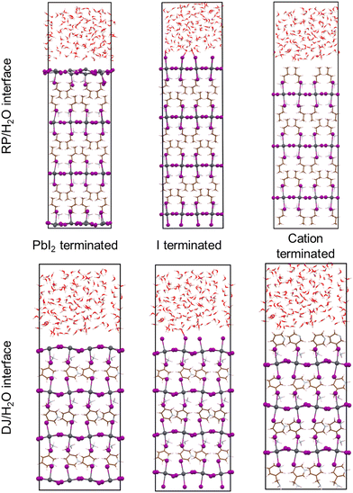
In this work, we have carried out ab initio molecular dynamics (AIMD) simulations to understand the nature of interactions of 2D hybrid perovskites at water interfaces. Here, we have focused on the different behaviour of two perovskite phases, DJ and RP, towards water. There are several experimentally synthesized 2D perovskites available for both the DJ and RP phases. The most widely studied RP phase 2D perovskites are n-butylammonium (BA) containing (BA)2PbI4 and phenylethylammonium (PEA) containing (PEA)2PbI4. Whereas in the case of the DJ phase, the popular systems are 3-aminomethylpyridinium (3-AMP) and 4-aminomethylpyridinium (4-AMP) based (3AMP)PbI4 and (4AMP)PbI4 perovskites. Since our work is mainly focused on the fundamental understanding of 2D perovskites, we have selected the perovskite system from two different perovskite phases, which have well-characterized crystal structures and are commonly studied for fundamental analysis. Thus, the perovskite systems we have considered in this study are the RP phase (BA)2PbI4/H2O interface and DJ phase (3AMP)PbI4/H2O interface. For both the systems, we have considered possible surface terminations as follows: (i) PbI2 termination where the PbI2 layer is present in direct contact with water molecules, (ii) iodine termination where axial iodides are interfaced with the water environment, (iii) organic spacer cation termination where organic spacer molecules are interfaced with water molecules (Fig. 1).
2. Computational details
For the considered RP and DJ phase perovskites, we have modelled 2 × 2 supercells of the respective (001) surfaces of PbI2-, I- and organic layer-terminated systems. The considered crystal structure for modelling these systems agrees with the reported lattice parameters from experiments.17,23 Further, a vacuum region of 15 Å on top of the perovskite slabs is considered to be filled up with water molecules. Owing to the experimental density of liquid water (1.003 g cm−3), we have filled the vacuum region with 150 water molecules with the help of PACKMOL software, thereby creating surface–water interface models of the 2D hybrid perovskites as shown in Fig. 1.24 The lattice parameters of all the considered systems are mentioned in Table S1 (ESI†).The AIMD simulations of the considered models have been carried out in the CP2K package implementing the Quickstep module, which has emerged as a robust tool for carrying out large-scale simulations in rapid time.25–27 A double-ζ basis set (DZVPMOLOPT) along with norm-conserving Goedecker–Teter–Hutter (GTH) pseudopotentials was used.28,29 A wave function CUTOFF = 500 Ry, and for the expansion of the electron density, a REL_CUTOFF = 50 Ry was used. The exchange–correlation potentials were implemented using PBE functional with the DFT-D3 van der Waals corrections as described by Grimme.30,31 A canonical ensemble method was appointed to fix the volume, and the temperature was controlled using a Nosé–Hoover thermostat with a target temperature of 350 K.32,33 For all the considered models, AIMD simulations were performed till 10 ps with a time step of 1 fs to understand the evolution of the perovskite surfaces in the presence of water. Similar timescales have been reported to be enough for 3D perovskite systems.21,22 Also, we have performed Bader charge analysis with the help of the Henkelman program to quantify the results and understand the impact of charges on elements as well as layers.34–37 To analyse the interactions between various kinds of atoms throughout the simulations, we have calculated the radial distribution functions (RDF), g(r) as,
 | (1) |
 | (2) |
The x-axis of the RDF plots typically refers to the ‘distance’ indicating the radial distance from the reference/central atom. The reference for ‘zero’ distance is usually the distance from the reference atom to itself, essentially indicating the distribution of neighbouring atoms around the reference atom. In general, the RDF plot illustrates how the density of neighbouring atoms varies as a function of distance from the central/reference atom. Peaks in the RDF plot indicate preferred distances where neighbouring atoms are likely to be found.
3. Results
Now, we have considered the simulations of all three terminated surfaces of both RP and DJ phases of 2D hybrid perovskites, which have been discussed separately henceforth.3.1. PbI2 termination
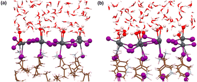
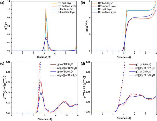
First, we analyse the PbI2-terminated surface–water interfaces of RP and DJ phases (Fig. 1). The post-simulation structures are provided in Fig. S1 (ESI†), and a zoomed view is presented in Fig. 2. From both Fig. S1 (ESI†) and Fig. 2, structural distortions of the Pb–I surface are visible in the surface–water interfaces for both phases. Thus, we have analysed various interactions using RDF plots.To understand the effect of water, we have separately plotted Pb–I RDFs for the surface and inner bulk layers, as shown in Fig. 3a and b. Two Pb–I layers in contact with water are referred to as surface layers, whereas two inner Pb–I layers are referred to as bulk layers. From Fig. 3a, the peaks for surface Pb–I bonds are found to be broader than those of bulk layers for both phases.
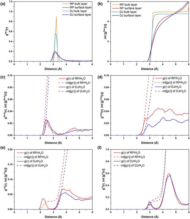
Different types of peaks for surface and bulk lead iodide layers indicate different bond strengths of Pb–I bonds in these layers. Since the bulk lead iodide layers do not come in contact with the water molecules, all Pb–I bonds keep the same bond length, resulting in a sharp peak in the RDF plot. Meanwhile, the Pb–I bonds present at the surface layer are strongly influenced by the presence of a water environment. Since the Pb and I atoms in the surface layer are interacting with the water molecules, the Pb–I bonding strength decreases, and hence, the Pb–I bond length varies for a range of values (∼2.8–3.8 Å), giving rise to a broad gPb–I(r) peak. From the integrated RDFs shown in Fig. 3b, the coordination environment of the Pb atoms can be grasped. The number of Pb–I interactions for each Pb atom is nearly 4 (Fig. 3b) for the surface layers compared to 5 for bulk layers at 3 Å in both phases. Upon comparing the surface layers for both phases, we can say that the coordination number for Pb–I bonds is less in the RP phase compared to the DJ phase (Fig. 3b). A decrease in the Pb–I coordination number means a smaller number of distinct Pb–I bonds, which infers that some of the Pb–I bonds are broken due to interaction with water molecules. Also, the lead iodide layer having a smaller Pb–I coordination number has lesser Pb–I bonds due to the stronger involvement of Pb and I atoms with water molecules. In other words, we can say that a smaller Pb–I coordination number means a stronger interaction of the lead iodide layer with water. Thus, stronger interaction with water is experienced by the RP phase compared to the DJ/H2O interface. From Bader analysis, we have observed that surface layer Pb atoms are more electropositive in nature (∼0.99 |e|) compared to the bulk layer Pb atoms (∼0.90 |e|), which results from the interaction with the water environment at the surface.
Also, we have studied the interactions happening at the interface between the surface atoms and water molecules. The possible interactions could be between Pb and water O atoms (Pb–O) and between I and water H atoms (I–Hw) (Fig. 2). Thus, we have plotted the RDFs for Pb–O and I–Hw, as presented in Fig. 3c and d. From Fig. 3c, the average Pb–O distance is found to be ∼2.6 Å, which suggests the interaction between surface Pb and a lone pair of water O atoms. The Pb–O interaction is found to be stronger in the RP phase compared to the DJ phase (Fig. 3c). This can also be confirmed from the integrated distribution plot in Fig. S2 (ESI†), where a larger number of Pb–O coordination is seen at shorter bond distances (till 3 Å) for the RP/H2O interface compared to the DJ/H2O interface. Such observation is supported by Pearson's hard-soft acid–base principle. Similar interactions are also found for 3D perovskites, as reported by De Angelis and coworkers.22
However, I–Hw interactions show a wide distribution in the RDF plot without any distinct peaks for both phases (Fig. 3d). The distributions start at ∼2.2 Å in both interfaces, thereby indicating hydrogen bonding interactions between I and water. From these findings, we can say that the RP/H2O interface experiences stronger Pb–O interaction, whereas both interfaces experience similar I–Hw interactions. Also, comparing the peak intensity of Pb–O and I–Hw RDFs (at 3 Å), we can see stronger interaction through Pb–O bond formation. So, we can mention that the PbI2 terminated RP phase interacts with the water to a larger extent compared to the DJ phase. Also, to understand the water adsorption nature of the perovskite surface, we have calculated adsorbed water molecules per metal for both phases. In Fig. S3 (ESI†), we have presented the histograms for the number of water molecules adsorbed per metal over the simulation trajectories. From the plot, we can notice high frequencies of the numbers 1.1 and 1.2 in the case of the RP/H2O interface compared to the DJ/H2O interface, inferring the adsorption of water molecules on the surface to a larger extent. Hence, we can conclude that decomposition via water adsorption would happen faster in the RP than in the DJ phase.
3.2. Iodine termination
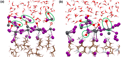
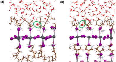
Here, we have analysed the I-terminated surface–water interfaces of RP and DJ phases (Fig. 1). The simulated structures of the same are presented in Fig. S4 (ESI†) with a zoomed view of the interface given in Fig. 4. From the simulated figures (Fig. S4, ESI† and Fig. 4), the distortion in the interfaces is very evident, especially in the formation of I2 molecules. Fig. S4 (ESI†) shows that the inner layers are largely unaffected, whereas the surface layers react with the water environment.To quantify these changes, we have plotted the RDFs averaged throughout the simulation trajectories. Again, we have categorized the inorganic layers as surface and bulk layers, and the RDF plots for Pb–I are represented in Fig. 5a. From Fig. 5a, sharp peaks are observed for bulk Pb–I layers compared to the broad peaks for surface Pb–I layers interacting with water molecules. For the RP/H2O interface, Pb–I RDF shows a sharp peak at 3.26 Å for the bulk layers, whereas the broad peak at 3.16 Å is observed for surface layers (Fig. 5a). That means the bulk lead iodide layer has distinct Pb–I bonds with a bond length of 3.26 Å, which remains intact throughout the simulation trajectory. But the surface layer is disturbed by the water interface where the Pb–I bond lengths range from 2.8 Å to 4.5 Å. A similar phenomenon was observed for the DJ/H2O interface, where bulk and surface Pb–I RDF peaks are found at 3.16 Å and 3.14 Å with sharp and broad distribution, respectively (Fig. 5a). From the integrated RDF plots, the number of bulk Pb–I interactions reaches 5 at 3.27 Å, whereas for surface Pb atoms, it ranges from 2 to 4 within 4 Å in the RP phase (Fig. 5b). Also, in the case of the DJ phase, the number of bulk Pb–I interactions reaches 5 within 3.60 Å, whereas for the surface, it ranges from 2 to 4 within 4 Å (Fig. 5b). This result indicates that after the interaction of lead iodide layers with water molecules, the number of Pb–I bonds for a particular Pb atom decreases to 2. That means Pb atoms remain coordinated only with two I atoms, whereas other coordination sites are occupied by the water O atoms. Instead, dissociated I atoms are involved in other interactions, which we will discuss in the following sections. These observations suggest the complete breakdown of the octahedral framework at the surface of I-terminated perovskites for both the water interface models.
During the simulation, different types of interactions occur between the surface and the water environment. In Fig. 4a, we have highlighted the bonding interactions experienced by the RP/H2O interface. Also, the decomposition of Pb–I bonds due to interaction with water is visible, leading to the formation of I2. Interestingly, for the DJ/H2O interface, we noticed one of the water molecules diffusing towards the spacer cation layer through inorganic slabs (Fig. 4b). Infiltration of water molecules through the DJ phase perovskite in the presence of moisture was also observed experimentally by Grätzel and coworkers.20 Infiltration of water can lead to nucleophilic substitution at the Pb metal centres, which triggers the release of I leading to I2 formation (Fig. 4).22 Thus, to quantify the interactions between surface Pb atoms and water O atoms, we have plotted the RDFs for Pb–O averaged over the simulation, as shown in Fig. 5c. The peaks for Pb–O interaction are seen at 2.45 and 2.56 Å for RP/H2O and DJ/H2O perovskite water interface models, respectively, which are within typical Pb–O bond lengths reported for lead oxide crystals.38 Also, similar Pb–O bond lengths at perovskite water interfaces were reported by De Angelis and coworkers.22 Hence, we can claim that strong bonding interactions are present between Pb and O in both RP and DJ phase iodine terminated surfaces. The stronger interaction in the case of the RP phase is also supported by the more positive charge on surface Pb atoms in this case (0.99 |e| for RP vs. 0.89 |e| for DJ). Next, we investigate the RDFs for interaction between surface I atoms and water H atoms (Hw), as shown in Fig. 5d. I–Hw interaction is detected by the peak starting at 2.65 Å for the RP/H2O interface, whereas for the DJ/H2O interface, the peak is broader and slightly right-shifted at 2.86 Å, referring to a weaker interaction strength compared to the RP phase (Fig. 5d). Noticeably, for both cases, the RDF broadens substantially after the peak due to long-range interactions. From these findings, we can highlight an unusual observation that the RP/H2O interface is much more sensitive to both the Pb–O and I–Hw interactions than the DJ phase. Despite the water infiltration that happens, the DJ/H2O interface is robust towards moisture compared to the RP phase. Similar observations are reported for the 3D analogue where the PbI2 terminated MAPbI3 perovskite structure remains undistorted even after water infiltration.22
Notably, from the AIMD simulation, we noticed a significant interaction between surface I atoms and water oxygen atoms (Fig. 4a). To support this observation, we have calculated the RDFs for I–O, as presented in Fig. 5e. For the RP/H2O interface, a peak at 2.24 Å indicates the formation of the I–O bond, whereas no such interaction is present in the DJ/H2O interface (Fig. 5e). This observation is also supported by the fact that few of the surface I atoms are positively charged in the RP/H2O interface, having charges around 0.43 |e|. These positively charged I atoms are responsible for the formation of I–O bonds. For both phases, a broad peak is observed close to 4 Å due to the water molecules present at larger distances. To investigate the I2 molecule formation detected in Fig. 4a and b, as some surface I atoms diffuse into the water environment, we have plotted the RDFs for the I–I interaction as presented in Fig. 5f. The peak observed at 3 Å indicates the formation of the I2 molecule (Fig. 5f). The later peak arising around the 4.5 Å region is due to other I atoms present in the inorganic layer. From charge analysis, the positively charged I (∼0.21 |e|) atoms combine with negatively charged I (∼−0.50 |e|) atoms to form the I2 molecule for both the phases of water interfaces. This occurrence can be correlated with the decrease in the Pb–I coordination number discussed earlier. Since the surface I atoms originally bonded with Pb diffuse and form I2, the Pb–I coordination number decreases eventually. From these observations, we can say that the I terminated water interfaces of both the RP and DJ perovskite phases face similar interactions with water, differing only in the I–O interactions. For both phases, I termination cannot be considered as a preferable termination from the water stability perspective due to the formation of I2 because of nucleophilic substitution of H2O at the Pb centres.
3.3. Cation termination
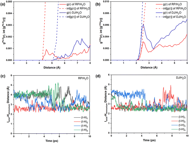
Now, we move on to study the simulation results of the cation-terminated surface–water interfaces for both phase perovskites (Fig. 1). In Fig. S5 (ESI†), we have presented the simulated geometries of two considered perovskites, and a zoomed view of the interfaces is shown in Fig. 6. Extensive water infiltration through the organic cation layer at the surface can be observed in the simulated structures (Fig. 6 and Fig. S5, ESI†). In this case, as the PbI layers are not at the surface, they are mostly found to be intact.Although water molecules did not cross the organic layer completely and react with the inorganic layer within the simulation time, we have analysed the robustness of the two cation terminated phases towards surface water molecules. Thus, we have further calculated the RDFs for interaction between Pb atoms and water O atoms for the cation-terminated water interface models (Fig. 7a). From Fig. 7a, Pb–O RDF in RP/H2O interface (BA cation) shows a broad distribution starting at 4.2 Å and a peak located at 4.55 Å. However, the Pb–O RDF in DJ/H2O interface (3AMP cation) shows a weak distribution starting as far as 5.2 Å (Fig. 7a). Thus, the 3AMP cation in the DJ/H2O interface is found to be more resistant to the water environment. This is also supported by the presence of more charge on the oxygen atoms of the water layer in the RP/H2O interface (−1.33 |e| per O) compared to the DJ/H2O interface (−1.29 |e| per O). This further supports the robustness of the 3AMP cation in comparison to the BA cation. Further, we have analysed the RDF for the interaction between I and water H atoms, as presented in Fig. 7b. The I–Hw RDFs show a peak at ∼2.55 Å (Fig. 7b). The high peak intensity for the DJ/H2O interface indicates its preferability to interact through I–Hw hydrogen bonding. The less pronounced nature of Pb–O interaction than I–Hw can be seen when comparing the intensity of Pb–O and I–Hw RDFs.
Since the polar water molecules are not able to diffuse into the perovskite through the hydrophobic organic chain, they can only reach up to an interacting distance of axial iodides of the inorganic layer (Fig. 6). This observation can be attributed to the robustness of organic cations that keep the PbI layer protected from water infiltration. To support the robustness of organic cations, we have verified the H-bonding interaction nature of the axial I and ammonium H of the surface organic layer. For both the perovskite phases, consistent interaction between axial I of the inorganic layer and ammonium H of surface organic cations interfacing with the water environment is observed throughout the simulations (Fig. 7c and d).
4. Discussions
Finally, one of the main goals of this study is to find the possible ways the perovskite structure degrades in the presence of water/moisture. In other words, which terminations are more prone to structural distortion in the presence of water? In this context, we have compared the RDFs of Pb–I interactions for all the considered systems as the Pb–I bond decomposition has been found to be the possible way for the initiation of instability in the presence of water. From Fig. 8a and b, one can notice that cation and PbI2 terminated water interfaces possess more intense peaks compared to the I terminated for both the RP and DJ phases. These results infer that there are a smaller number of Pb–I bonds with an exact bond length in iodine terminated surfaces, which indicates a decomposed state of this surface in the presence of moisture. Meanwhile, the Pb–I bonds for the cation terminated surfaces remain stronger even in the presence of moisture due to the strong van der Waals forces present in the organic cations. In addition, Fig. 8c and d shows the highest number of Pb–I interactions for the cation terminated water interfaces. For the RP/H2O interface, the Pb–I coordination number reaches 4.95 at 3.8 Å for cation terminated models, whereas it remains at ∼4.5 for the other two surfaces (Fig. 8c). Similarly, for the DJ/H2O interface, till 3.8 Å bond length, the Pb–I coordination number for the PbI2, I and cation termination are 4.45, 4.05 and 4.8, respectively (Fig. 8d). Hence, we can claim that there is a much stronger bonding interaction between Pb and I in the case of cation terminated perovskite water interfaces compared to the PbI2 and I terminated models. The retention of bonding interactions in the cation terminated structure is due to the hydrophobicity of bulky surface cations, keeping the inorganic layer safe from degradation. The same is also visible from the post simulation geometries of cation terminated models in Fig. S5 (ESI†).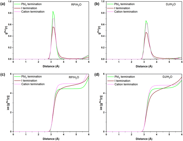 | ||
| Fig. 8 Radial pair distribution plots of Pb–I for (a) RP/H2O, and (b) DJ/H2O interfaces. Integrated distribution plots of Pb–I for (c) RP/H2O and (d) DJ/H2O interfaces. | ||
From our findings, we can mention some major events that could possibly happen with 2D hybrid perovskites in the presence of moisture. Primarily, 2D hybrid perovskite surfaces terminated with large organic spacer molecules emerge as the most stable surface terminations against moisture. Among inorganic layer terminated surfaces, PbI2 termination is found to be more stable compared to I termination. This happens due to the stability of the PbI2 surface, fulfilling the charge and coordination number of Pb and I. On the other hand, in the I terminated interface, the presence of unsaturated iodides leads to locally charged surfaces, making them more reactive towards the water environment. Another point worth mentioning is that even for the I terminated water interface models, the inside Pb–I layers away from the surface do not undergo much change during the simulations (Fig. S4, ESI†). This can be attributed to the robustness of the large organic ammonium layers, which prevent water infiltration due to their hydrophobic nature. Similarly, the cation terminated water interfaces are also quite robust. The possible degradation pathway of the I terminated surface could be through I2 formation.
De Angelis and coworkers have carried out fundamental research work on the stability of 3D halide perovskites in the presence of water.21,22 For the most studied system MAPbI3, they reported that PbI2 termination is much more stable at water interfaces due to strong Pb–I bonds compared to the MAI terminated surface, in which case both MA and I are prone to dissolution as water molecules interact with the Pb nodes.21 In another work, they have considered only the metal–I2 terminations to compare MAPbI3, MASnI3 and DMASnBr3.22 Here, they found that Sn–I bonds of the SnI2 layer also break in the presence of water. On the other hand, SnBr3 is found to form an amorphous surface layer preventing water infiltration, but such layers can be detrimental to photovoltaic applications. In our work, we have found that in the case of the considered 2D halide perovskites, the PbI2 termination is quite stable due to strong Pb–I bonds. The most noteworthy feature is the unique arrangement of the organic cation layer that prevents water infiltration by virtue of hydrophobicity, which also protects the inner inorganic Pb–I layers. The bulky organic cation layer also remains intact, unlike MA or similar small cations in 3D perovskites.21,22 The cation termination can be helpful in maintaining stability in the presence of moisture without the requirement of an amorphous surface layer, thereby preserving the optoelectronic properties of 2D hybrid perovskites.
5. Conclusions
Understanding the stability of perovskite systems in environmental conditions, especially in the presence of water, is crucial for the application of these materials in photovoltaics or other applications. In this regard, we have carried out a systematic ab initio molecular dynamics-based study to investigate the stability of 2D hybrid perovskites at the water interface. Analysing the time-averaged structures, we have been able to figure out possible degradation pathways of the 2D hybrid perovskites in the presence of a liquid water environment. We have considered all possible terminations (PbI2, I-, organic cation-) of both the Ruddlesden–Popper (RP) and Dion–Jacobson (DJ) phases. PbI2 terminated surfaces are found to experience interaction through Pb–O bond formation, and in this case, the DJ/H2O interface is more robust compared to the RP/H2O interface. In the case of the I terminated interfaces, I2 formation is most prominent, resulting from nucleophilic substitution of water molecules at Pb metal centres. This phenomenon is expected to be the possible degradation route for this type of 2D hybrid perovskite system in contact with water molecules. Despite water infiltration through the surface PbI6 octahedral layer, DJ phase perovskites possess less pronounced interaction compared to the RP phase. Cation terminated interfaces are found to be more robust towards the water environment. The presence of bulky organic cations (like 3AMP and BA) in 2D perovskites plays an important role in both PbI2 terminated and organic cation terminated structures by preventing water infiltration inside inorganic layers. Also, we observed BA and 3AMP cations to interact differently with water molecules. Thus, tuning the organic cation layer can be an ingenious way to maintain the moisture stability of optoelectronic devices based on 2D hybrid perovskites. Overall, our work represents the fundamental understanding regarding the stability and degradation of 2D DJ and RP phase perovskites in the presence of moisture and directs the perovskite community towards further design and development in perovskite research and application.Conflicts of interest
There are no conflicts to declare.Acknowledgements
We thank IIT Indore for lab and computing facilities. This work is supported by DST-SERB (Project Number CRG/2022/000836), CSIR (Project Number 01(3046)/21/EMR-II), and BRNS (Project Number 2023-BRNS/12356). E. M. thanks MoE for the research fellowship. S. S. M. thanks CSIR for the research fellowship.References
- A. Kojima, K. Teshima, Y. Shirai and T. Miyasaka, J. Am. Chem. Soc., 2009, 131, 6050–6051 CrossRef CAS PubMed
.
- M. M. Lee, J. Teuscher, T. Miyasaka, T. N. Murakami and H. J. Snaith, Science, 2012, 338, 643–647 CrossRef CAS PubMed
.
- J. Burschka, N. Pellet, S.-J. Moon, R. Gao, P. Humphry-Baker, M. K. Nazeeruddin and M. Grätzel, Nature, 2013, 499, 316 CrossRef CAS PubMed
.
- M. Saliba, S. Orlandi, T. Matsui, S. Aghazada, M. Cavazzini, J.-P. Correa-Baena, P. Gao, R. Scopelliti, E. Mosconi and K.-H. Dahmen,
et al.
, Nat. Energy, 2016, 1, 15017 CrossRef CAS
.
- W. S. Yang, J. H. Noh, N. J. Jeon, Y. C. Kim, S. Ryu, J. Seo and S. I. Seok, Science, 2015, 348, 1234 CrossRef CAS
.
- K. Yoshikawa, H. Kawasaki, W. Yoshida, T. Irie, K. Konishi, K. Nakano, T. Uto, D. Adachi, M. Kanematsu, H. Uzu and K. Yamamoto, Nat. Energy, 2017, 2, 17032 CrossRef CAS
.
- A. K. Jena, A. Kulkarni and T. Miyasaka, Chem. Rev., 2019, 119, 3036–3103 CrossRef CAS PubMed
.
- J. M. Frost, K. T. Butler, F. Brivio, C. H. Hendon, M. van Schilfgaarde and A. Walsh, Nano Lett., 2014, 14, 2584–2590 CrossRef CAS PubMed
.
- Y. Zhao and K. Zhu, Chem. Commun., 2014, 50, 1605–1607 RSC
.
- I. C. Smith, E. T. Hoke, D. Solis-Ibarra, M. D. McGehee and H. I. Karunadasa, Angew. Chem., Int. Ed., 2014, 53, 11232–11235 CrossRef CAS PubMed
.
- C. C. Stoumpos, D. H. Cao, D. J. Clark, J. Young, J. M. Rondinelli, J. I. Jang, J. T. Hupp and M. G. Kanatzidis, Chem. Mater., 2016, 28, 2852–2867 CrossRef CAS
.
- L. N. Quan, M. Yuan, R. Comin, O. Voznyy, E. M. Beauregard, S. Hoogland, A. Buin, A. R. Kirmani, K. Zhao, A. Amassian, D. H. Kim and E. H. Sargent, J. Am. Chem. Soc., 2016, 138, 2649–2655 CrossRef CAS PubMed
.
- G. Kieslich, S. Sun and A. K. Cheetham, Chem. Sci., 2014, 5, 4712–4715 RSC
.
- C. Katan, N. Mercier and J. Even, Chem. Rev., 2019, 119, 3140–3192 CrossRef CAS PubMed
.
- D. Sapori, M. Kepenekian, L. Pedesseau, C. Katan and J. Even, Nanoscale, 2016, 8, 6369–6378 RSC
.
- E. Mahal, D. Roy, S. S. Manna and B. Pathak, J. Mater. Chem. A, 2023, 11, 23547–23555 RSC
.
- X. Li, W. Ke, B. Traoré, P. Guo, I. Hadar, M. Kepenekian, J. Even, C. Katan, C. C. Stoumpos and R. D. Schaller,
et al.
, J. Am. Chem. Soc., 2019, 141, 12880–12890 CrossRef CAS PubMed
.
- A. A. Sutanto, N. Drigo, V. I. Queloz, I. Garcia-Benito, A. R. Kirmani, L. J. Richter, P. A. Schouwink, K. T. Cho, S. Paek, M. K. Nazeeruddin and G. Grancini, J. Mater. Chem. A, 2020, 8, 2343–2348 RSC
.
- S. Ahmad, P. Fu, S. Yu, Q. Yang, X. Liu, X. Wang, X. Wang, X. Guo and C. Li, Joule, 2019, 3, 794–806 CrossRef CAS
.
- A. Ducinskas, G. Y. Kim, D. Moia, A. Senocrate, Y.-R. Wang, M. A. Hope, A. Mishra, D. J. Kubicki, M. ło Siczek, W. Bury, T. Schneeberger, L. Emsley, J. V. Milic, J. Maier and M. Gratzel, ACS Energy Lett., 2021, 6, 337–344 CrossRef CAS
.
- E. Mosconi, J. M. Azpiroz and F. De Angelis, Chem. Mater., 2015, 27, 4885–4892 CrossRef CAS
.
- W. Kaiser, D. Ricciarelli, E. Mosconi, A. A. Alothman, F. Ambrosio and F. De Angelis, J. Phys. Chem. Lett., 2022, 13, 2321–2329 CrossRef CAS PubMed
.
- D. G. Billing and A. Lemmerer, Acta Crystallogr., Sect. B: Struct. Sci., 2007, 63, 735–747 CrossRef CAS PubMed
.
- L. Martínez, R. Andrade, E. G. Birgin and J. M. Martínez, J. Comput. Chem., 2009, 30, 2157–2164 CrossRef PubMed
.
- J. Hutter, M. Iannuzzi, F. Schiffmann and J. VandeVondele, Comput. Mol. Biosci., 2014, 4, 15–25 CrossRef CAS
.
- T. D. Kühne, M. Iannuzzi, M. D. Ben, V. V. Rybkin, P. Seewald, F. Stein, T. Laino, R. Z. Khaliullin, O. Schütt, F. Schiffmann, D. Golze, J. Wilhelm, S. Chulkov, M. H. Bani-Hashemian, V. Weber, U. Borštnik, M. Taillefumier, A. S. Jakobovits, A. Lazzaro, H. Pabst, T. Müller, R. Schade, M. Guidon, S. Andermatt, N. Holmberg, G. K. Schenter, A. Hehn, A. Bussy, F. Belleflamme, G. Tabacchi, A. Glöβ, M. Lass, I. Bethune, C. J. Mundy, C. Plessl, M. Watkins, J. VandeVondele, M. Krack and J. Hutter, J. Chem. Phys., 2020, 152, 194103 CrossRef PubMed
.
- J. VandeVondele, M. Krack, F. Mohamed, M. Parrinello, T. Chassaing and J. Hutter, Comput. Phys. Commun., 2005, 167, 103–128 CrossRef CAS
.
- J. VandeVondele and J. Hutter, J. Chem. Phys., 2007, 127, 114105 CrossRef PubMed
.
- S. Goedecker, M. Teter and J. Hutter, Phys. Rev. B: Condens. Matter Mater. Phys., 1996, 54, 1703–1710 CrossRef CAS PubMed
.
- P. Perdew, K. Burke and M. Ernzerhof, Phys. Rev. Lett., 1996, 77, 3865–3868 CrossRef PubMed
.
- S. Grimme, J. Antony, S. Ehrlich and H. A. Krieg, J. Chem. Phys., 2010, 132, 154104 CrossRef PubMed
.
- S. A. Nosé, J. Chem. Phys., 1984, 81, 511–519 CrossRef
.
- W. G. Hoover, Phys. Rev. A: At., Mol., Opt. Phys., 1986, 34, 2499–2500 CrossRef PubMed
.
- R. F. W. Bader, Chem. Rev., 1991, 91, 893–928 CrossRef CAS
.
- E. Sanville, S. D. Kenny, R. Smith and G. Henkelman, J. Comput. Chem., 2007, 28, 899–908 CrossRef CAS PubMed
.
- W. Tang, E. Sanville and G. A. Henkelman, J. Phys.: Condens. Matter, 2009, 21, 084204 CrossRef CAS PubMed
.
- G. Henkelman, A. Arnaldsson and H. Jónsson, Comput. Mater. Sci., 2006, 36, 354–360 CrossRef
.
- C. E. Avalos, B. J. Walder and L. Emsley, J. Phys. Chem. C, 2019, 123, 15744–15750 CrossRef CAS
.
Footnote |
| † Electronic supplementary information (ESI) available: The supplementary information file includes lattice parameters, post-simulation geometries of different models, integrated RDF plots, and histograms for the number of adsorbed waters per metal. See DOI: https://doi.org/10.1039/d4ya00235k |
| This journal is © The Royal Society of Chemistry 2024 |

