
 Open Access Article
 This Open Access Article is licensed under a
 Creative Commons Attribution 3.0 Unported Licence
All-iron redox flow battery in flow-through and flow-over set-ups: the critical role of cell configuration†
Josh J.
Bailey
 a,
Maedeh
Pahlevaninezhad
b,
H. Q. Nimal
Gunaratne
a,
Hugh
O’Connor
a,
Kate
Thompson
a,
Pranav
Sharda
a,
Paul
Kavanagh
a,
Oana M.
Istrate
c,
Stephen
Glover
c,
Peter A. A.
Klusener
d,
Edward P. L.
Roberts
*b and
Peter
Nockemann
*a
a,
Maedeh
Pahlevaninezhad
b,
H. Q. Nimal
Gunaratne
a,
Hugh
O’Connor
a,
Kate
Thompson
a,
Pranav
Sharda
a,
Paul
Kavanagh
a,
Oana M.
Istrate
c,
Stephen
Glover
c,
Peter A. A.
Klusener
d,
Edward P. L.
Roberts
*b and
Peter
Nockemann
*a
aThe QUILL Research Centre, School of Chemistry and Chemical Engineering, Queen's University Belfast, Belfast, BT9 5AG, UK. E-mail: p.nockemann@qub.ac.uk
bDepartment of Chemical and Petroleum Engineering, University of Calgary, Calgary, ABT2N 1N4, Canada. E-mail: edward.roberts@ucalgary.ca
cThe School of Mechanical and Aerospace Engineering, Queen's University Belfast, Belfast, BT9 5AH, UK
dShell Global Solutions International B.V., Energy Transition Campus Amsterdam, Grasweg 31, 1031 HW Amsterdam, The Netherlands
First published on 7th May 2024
Abstract
Significant differences in performance between the two prevalent cell configurations in all-soluble, all-iron redox flow batteries are presented, demonstrating the critical role of cell architecture in the pursuit of novel chemistries in non-vanadium systems. Using a ferrocyanide-based posolyte, and a negolyte containing a hydroxylamine-based iron complex, higher maximum power density, energy efficiency, and electrolyte utilisation were observed with a flow-over cell that incorporated a carbon paper, compared with a flow-through configuration that used a graphite felt. Capacity fade was lower in the flow-over case, likely the result of a set-up with lower overpotentials, as indicated by polarisation curve analysis. Capacity fade in the flow-through case increased upon lowering current density, suggesting a different degradation pathway, dominated instead by electrolyte cross-over. These findings highlight the potential of novel non-vanadium chemistries in both flow-through and flow-over cells, prompting further research exploration of cell architectures.
Introduction
Climate change, air pollution, and energy security concerns have accelerated the proliferation of renewable energy generation. Given the intermittent and non-dispatchable nature of wind, solar, and other renewable energy sources, there is an increasing need for energy storage that will help balance electrical grids, and in some cases facilitate the transition to decentralised energy systems.1,2 Although global energy storage is currently dominated by pumped hydro storage,3 electrochemical energy storage (EES) is the fastest growing alternative.4 Li-ion batteries (LIB) currently dominate commercialised EES, although safety concerns and the social and environmental issues associated with sourcing Li and Co have accelerated research and development of several other battery types. One such type is the aqueous redox flow battery (RFB), which has been shown to have inherent safety advantages given its use of water-based electrolytes (cf. flammable organic solvents in LIB). Moreover, the redox reactions in an RFB occur on an electroactive surface rather than inside layered electrodes, such that system lifetime is forecast to be ca. 20 years (cf. <10 years for LIB).5 As liquids are pumped from external tanks through an electrochemical cell, the independent scaling of energy and power in RFBs lends itself well to industrial-sized installations, and recent studies have shown that for long-duration storage, costs are likely lower for RFBs than LIBs when storing energy for eight hours or more.6The archetypal RFB is the all-vanadium redox flow battery (VRFB), comprising vanadium active species solubilised in dilute sulfuric acid as both the positive electrolyte (posolyte) and negative electrolyte (negolyte). This RFB chemistry has been semi-commercialised, due to its long cycle life and the ability to mitigate electrolyte cross-over through the membrane by electrolyte mixing.7 However, this technology suffers from: low energy density; the need for expensive components to withstand corrosive electrolytes; and both the high cost and price volatility associated with vanadium.8 Although work is on-going to improve the performance and cost-effectiveness of vanadium RFBs,9 many other chemistries have been explored, including: iron/chromium,10 zinc/bromine,11 polysulfide/bromide,12 aqueous-organic,13,14 and all-organic elecrolytes.15,16 Indeed, comprehensive work exploring these various chemistries in detail has recently been published by Skyllas-Kazacos and co-workers.17
Avoiding the toxicity of chromium and bromine, the relatively low solubility of organic molecules in water,18 and the inherent flammability of all-organic systems, an alternative aqueous system is the hybrid all-iron RFB. This type of flow battery comprises an iron-based posolyte and negolyte based on a more abundant metal than vanadium.19,20 Despite clear safety and environmental benefits vs. vanadium, this RFB does not allow independent scaling of energy and power, given the Fe(II)/Fe(0) plating electrode in this hybrid system. Moreover, non-uniform plating issues and a tendency for the hydrogen evolution reaction (HER) at the negative electrode have tempered commercialisation.21 It should be noted, however, that research efforts have sought to mitigate the HER by operating at slightly elevated pH vs. that of a strongly acidic electrolyte,22 and commercial deployment of hybrid all-iron RFB systems is beginning to take place.
Further advancements in all-iron RFB technology have been made through the development of soluble iron-based electrolytes, aimed at retaining independent energy and power scaling and circumventing dendrite growth issues associated with hybrid systems. Metal-ion coordination complexes have been investigated as redox couples by judicious choice of ligands to shift their formal potential appropriately. For example, Chen et al. studied the Fe(III)/Fe(II) couple in acidic media with ligands closely linked to bipyridine and o-phenanthroline.23 These ligands conferred a more positive formal potential vs. the uncomplexed couple (E° = +0.77 V vs. the standard hydrogen electrode (SHE)), given their propensity to stabilise Fe2+ (d6) complexes via the low-lying vacant π*-orbitals of the ligands. However, the Fe(III) complexes were found to decay in acidic media by ligand loss. Ibanez et al. expanded the ligand pool to include those related to ethylene-diaminetetraacetic acid (EDTA) and ethylenediamine and demonstrated that a wide range of transition metal complexes displayed (quasi-) reversible redox properties, albeit within certain pH ranges.24 Negative formal potentials were uncovered for some complexes, with a particularly low E° = −0.81 V (vs. SHE) with triethanolamine (Fe-TEOA).
Wen et al. were first to combine this negative redox couple with a well-established positive redox couple, ½Br2/Br−, giving a cell potential close to 2.0 V.25 The authors showed that, in the presence of 3 M NaOH, the solubility of the Fe(III)-TEOA complex could be raised from 0.15 M (Fe![[thin space (1/6-em)]](https://www.rsc.org/images/entities/char_2009.gif) :ligand ratio of 1:2)24 to 0.60 M (Fe:ligand ratio of 1:2.33),25 although the maximum solubility of the Fe(II)-TEOA complex was reported as only 0.40 M (Fe:ligand ratio of 1:5). Further work from the same authors investigated negolytes using EDTA, oxalate, and citrate, finding high solubility but slow electrode kinetics for the latter.26 Moreover, the Fe(II)-oxalate complex was shown to be unstable and although Fe(III)/Fe(II)-EDTA gave energy efficiencies of ∼70% at pH ≈ 6, only low concentrations of ca. 0.1 M were demonstrated in full cells.
:ligand ratio of 1:2)24 to 0.60 M (Fe:ligand ratio of 1:2.33),25 although the maximum solubility of the Fe(II)-TEOA complex was reported as only 0.40 M (Fe:ligand ratio of 1:5). Further work from the same authors investigated negolytes using EDTA, oxalate, and citrate, finding high solubility but slow electrode kinetics for the latter.26 Moreover, the Fe(II)-oxalate complex was shown to be unstable and although Fe(III)/Fe(II)-EDTA gave energy efficiencies of ∼70% at pH ≈ 6, only low concentrations of ca. 0.1 M were demonstrated in full cells.
Using a similar approach but in alkaline media, a Co-complex (posolyte) was combined with and an Fe-complex (negolyte).27 This system illustrated that similar ligands with different transition metals can give vastly different redox potentials; here the cobalt redox couple was observed at E° = +0.12 V (vs. SHE) with a methylated analogue of TEOA, (cf. E° = −0.81 V (vs. SHE) for TEOA). The authors highlighted the importance of maintaining a molar excess of [OH]− anions to preclude the formation of other species favoured at pH < 14. Although this system was cheaper than the VRFB, its stability was only demonstrated for 30 cycles, and its energy density was limited by both an open-circuit voltage (OCV) below 1.0 V and only moderate solubility of the complexes (<0.50 M). Further work on Fe–Co RFBs was carried out by the group of Kwon, who identified a formulation in which Co-TEOA demonstrated improved cycling stability (100 cycles) and an OCV close to 1.0 V.28 However, the energy efficiency of this system was low at only 60% at 40 mA cm−2. By replacing TEOA with triisopropanolamine (TiPA), the same researchers improved the cycling stability (capacity fade <1% per day), whilst demonstrating an improved energy efficiency of 77% at 40 mA cm−2.29 The researchers then incorporated 3-[bis (2-hydroxyethyl)amino]-2-hydroxypropanesulfonic acid (DIPSO) as a ligand on the Fe-side, which proved more stable than its TiPA analogue.30 Although a low capacity-loss rate of 0.018 A h L−1 cycle−1 was shown, the volumetric capacity was still limited by the relatively low OCV of ca. 1.0 V.
To attain higher cell potentials, work has since focused on all-soluble, all-iron systems that pair two Fe-centred complexes with a difference in redox potential of greater than 1.0 V, often by selecting Fe(CN)63−/4− (Fe-CN) as the posolyte (for example, see Fig. 1 for the chemistry investigated in this work).
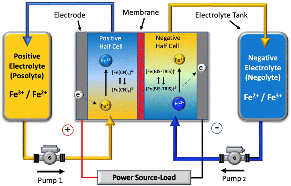 | ||
| Fig. 1 Schematic of a single cell of the all-soluble, all-iron redox flow battery operated in this work. | ||
Gong et al. studied an alkaline system comprising Fe-CN and Fe-TEOA with a standard cell voltage of 1.22 V (cf. 1.26 V for VRFB).31 This system demonstrated a reasonable energy efficiency of 73% when cycled at 40 mA cm−2. However, the authors noted that the capacity decreased in the first 20 cycles and oscillated thereafter, indicating a level of instability. The initial capacity decay was ascribed to membrane cross-over of free TEOA and its subsequent oxidation, which aligns with previous reports.25,27 Despite greater potential for high volumetric capacity, only ca. 6 A h L−1 (0.20 M) was reported.
Concurrently, symmetric RFB work aimed at understanding the pH-dependent cycling stability of the Fe-CN posolyte was conducted by Luo and co-workers.32 This redox couple was shown to function best at neutral or near-neutral conditions, where capacity decay was shown to be at its worst in strongly alkaline (pH = 14) conditions. On the other hand, Páez et al. employed a symmetric RFB to show that the Fe-CN redox couple was in fact stable at pH = 14, provided that the oxygen evolution reaction (OER) was avoided.33 The authors showed that the OER does not play a role in the neutral Fe-CN posolyte but at high pH, it may be thermodynamically favoured and thus will occur unless the kinetics are sluggish. The capacity loss seen in their system was comparably low vs. the work of Luo et al.,32 which was attributed to much lower overpotentials and less of a driving force for the OER. The same group have since presented an electrochemical charge-balancing protocol to overcome the impacts of unwanted side-reactions in related systems.34
On the negolyte side, Lenninger et al. investigated the cross-over of free TEOA ligands by electroosmotic drag,35 implying a high cross-over rate of the order of 10 mL Ah−1, and supporting Gong et al. in their assessment of the reason for capacity decay.31 Lê et al. investigated the same Fe-TEOA/Fe-CN RFB system, but used close to stoichiometric amounts of TEOA and iron (III) sulfate (Fe2(SO4)3·xH2O).36 The authors presented solid-state single-crystal X-ray diffraction data supporting the formation of a di-nuclear complex when formulating electrolytes with low Fe-ligand ratios (∼1:1.25) and supporting previous work with regards to the existence of a mono-nuclear complex at Fe-ligand ratios of 1:2 and above.27 As opposed to the Nafion® membranes used previously, Sreenath et al. explored the use of a sulfonated polyethylene styrene-divinylbenzene membrane,37 demonstrating a high energy efficiency of 75%, albeit at a low current density of 5 mA cm−2. Although the capacity retention was high, this was limited to 40 cycles and the volumetric capacity was very low (<2 A h L−1). Nonetheless, the work demonstrated the potential to use alternative fluorine-free membranes with high stability in alkaline conditions; the membrane withstood 1440 h in a highly alkaline oxidative environment.
Shin et al. later investigated both TEOA and DIPSO as ligands in an all-soluble, all-iron RFB.38 The authors proposed DIPSO, used previously in Fe-Co RFBs,30 as an alternative to TEOA, since the Fe-complex formed using the latter tended to reduce to metallic iron at negative potentials (<1.25 V vs. Ag/AgCl).39 The stronger bonding between DIPSO and the Fe-ion core was cited as the reason for the greater stability demonstrated in cyclic voltammograms. It should be noted, however, that the issue of metallisation may also be mitigated by the adoption of a high concentration of [OH]− anions and excess ligand.28 Nevertheless, the Fe-DIPSO negolyte demonstrated stronger resistance to reduction to metallic iron, and displayed good energy efficiency (70%) at a high current density of 80 mA cm−2, and good capacity retention (0.12% capacity loss/cycle) over 100 cycles. An added advantage of the DIPSO ligand was ascribed to its larger size and thus reduced cross-over, which was investigated later by the same group.40 The permeability of metal-ion complexes was shown to be significantly lower than that of metal-ions by the application of cyclic voltammetry and UV-Vis spectroscopy to samples generated by H-cell cross-over testing. The relative expense of DIPSO vs. TEOA, however, disfavours its commercial use.
Shin et al. subsequently introduced a larger, but cheaper, ligand with a similar motif, namely 2,2-bis(hydroxymethyl)-2,2′,2′-nitrilotriethanol (BIS-TRIS) and coupled it with Fe-CN to give an OCV of 1.43 V.41 The authors demonstrated good energy efficiency (73%) at 80 mA cm−2 across 250 cycles, citing its stability with respect to undesirable side reactions. This represents the longest cycle stability test to date for an all-soluble, all-iron RFB. The group then optimised their formulation in follow-up work.42 It was found that the solubility of Fe-BIS-TRIS could be raised from 1.33 M to 2.00 M when the ligand ratio was changed from 1:241 to 1:1.542 and the concentration of [OH]− anions was chosen to both maximise ligand deprotonation and stabilise the complex. For a 0.5 M solution, this resulted in a 1:1.5:9 Fe:ligand:base ratio and the optimised system was shown to give an energy efficiency (78%) close to incumbent VRFB technology. However, cycling stability was only demonstrated across 25 cycles and the authors suggested further research was required to lower the electrolyte viscosity and increase the accessible state-of-charge (SOC) window.
Table 1 shows a summary of the all-soluble iron RFB systems in the literature, highlighting the various OCVs of the different redox pairings, the gradual average increase in accessible current densities and, importantly, the predominant use of the “flow-through” cell configuration. It is important to note that the traditional “flow-through” configuration corresponds to the use of flow frame manifolds that deliver and receive electrolyte from two opposite sides of a cavity which is occupied by a porous electrode, usually a carbon felt.43–45 In contrast to this approach, a “flow-over” configuration refers to a system similar to that seen in low-temperature polymer electrolyte fuel cells, wherein the macroscopic flow of electrolyte is guided around a flow field, usually a piece of machined graphite, and allowed to diffuse into a thinner electrode cavity. In this case, graphitised papers are much more common, although there are some examples of “flow-over” set-ups that use thin pieces of carbon felt.46 These configurations will henceforth be referred to as FT (for “flow-through”) and FO (for “flow-over”). Fig. 2 shows a schematic that demonstrates the principal differences between the two cell configurations.
| Authors | Posolyte | Negolyte | Conc. (M) | OCV (V) | Max. EE (%) | Current density (mA cm−2) | Cycling stability (# cycles) | Cell configuration | Electrode material | Citation |
|---|---|---|---|---|---|---|---|---|---|---|
| Wen | Br2/2Br− | Fe-TEOA | 0.40 | 1.98 | 70 | 20 | 5 | Flow-through | Graphite felt | 25 |
| Wen | Br2/2Br− | Fe-EDTA | 0.10 | 1.04 | 80 | 10 | 10 | Flow-through | Graphite felt | 26 |
| Arroyo-Currás | Co-mTEOA | Fe-TEOA | 0.50 | 0.93 | 71 | 30 | 30 | Flow-over | Carbon paper | 27 |
| Gong | Fe-CN | Fe-TEOA | 0.20 | 1.34 | 73 | 40 | 110 | Flow-over | Carbon paper | 31 |
| Luo | Fe-CN | Fe-CN | 0.20 | N/A | 73 | 40–100 | N/A | Flow-through | Graphite felt | 32 |
| Lenninger | Fe-CN | Fe-TEOA | 0.20 | — | 73 | 40–100 | — | — | — | 35 |
| Aguiló-Aguayo | Fe-CN | Fe-TEOA | 0.20 | 1.35 | — | 2–5 | — | Flow-through | Embroidered stainless steel | 66 |
| Lê | Fe-CN | Fe-TEOA | 0.78 | 1.30 | 69 | 40 | 50 | Flow-through | Graphite felt | 36 |
| Noh | Co-TEOA | Fe-TEOA | 0.40 | 0.95 | 60 | 40 | 100 | Flow-through | Graphite felt | 28 |
| Sreenath | Fe-CN | Fe-TEOA | 0.20 | 1.52 | 69 | 15 | 40 | Flow-over | Carbon paper | 67 |
| Shin | Fe-CN | Fe-TEOA | 0.50 | 1.37 | 70 | 80 | 100 | Flow-through | Graphite felt | 38 |
| Fe-DIPSO | 70 | 80 | 100 | |||||||
| Noh | Co-TiPA | Fe-TiPA | 0.64 | 0.96 | 77 | 40 | 100 | Flow-through | Graphite felt | 29 |
| Noh | Co-TiPA | Fe-DIPSO | 0.60 | 0.93 | 62 | 40 | 100 | Flow-through | Graphite felt | 30 |
| Schroeder | Fe-CN | Fe-racEDDHA | 0.17 | 0.85 | 68 | 20 | 75 | Flow-through | Graphite felt | 68 |
| Shin | Fe-CN | Fe-BIS-TRIS | 0.50 | 1.43 | 73 | 80 | 250 | Flow-through | Graphite felt | 41 |
| Shin | Fe-CN | Fe-BIS-TRIS | 2.00 | 1.43 | 78 | 80 | 25 | Flow-through | Graphite felt | 42 |
| Bailey | Fe-CN | Fe-BIS-TRIS | 0.50 | 1.29 | 86 | 10–100 | 30 | Flow-over & Flow-through | Graphite felt & Carbon paper | This work |
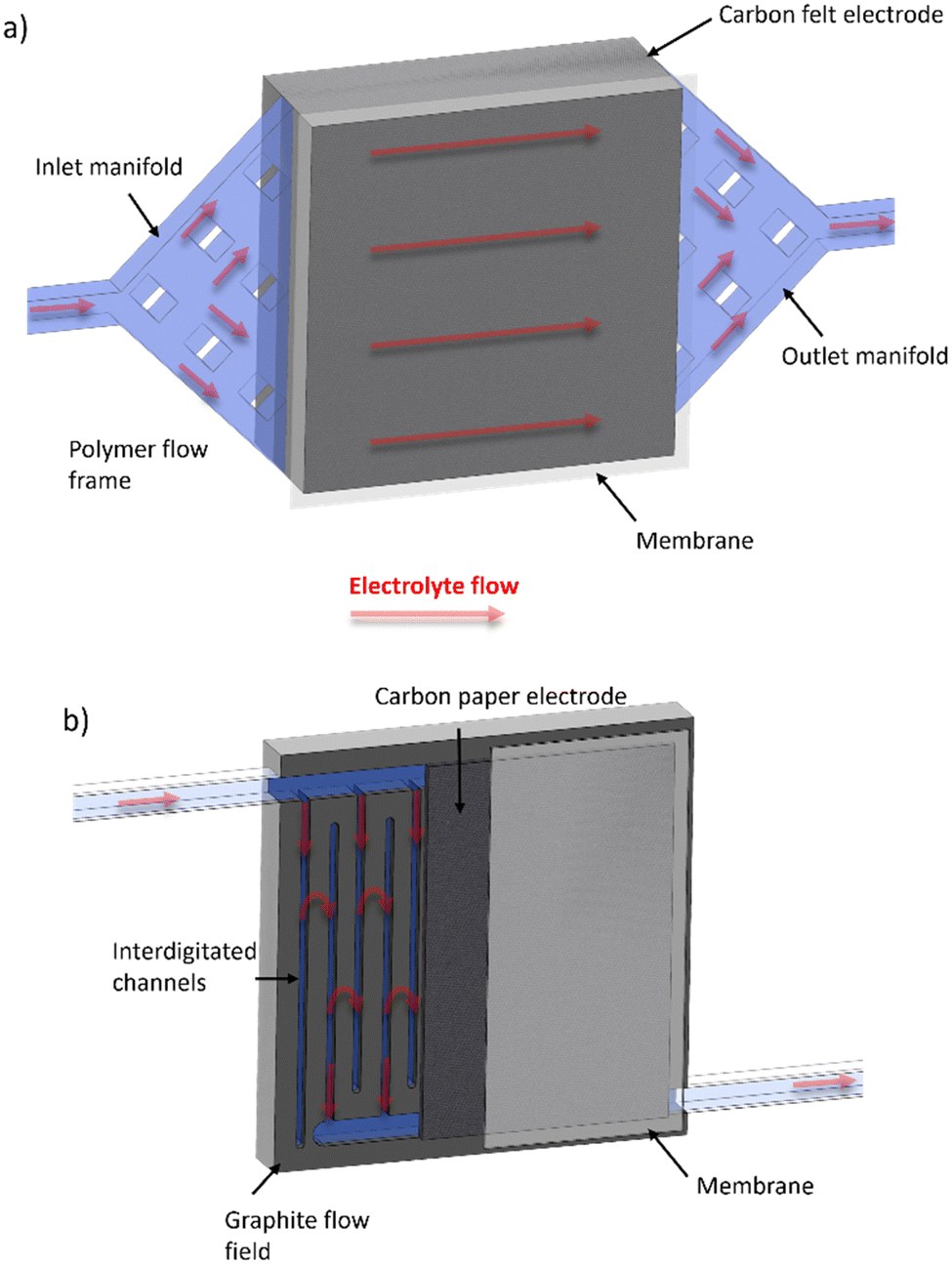 | ||
| Fig. 2 Schematic of (a) FT and (b) FO (with inter-digitated flow field pattern) configurations, with electrolyte flow direction shown with red arrows through porous regions highlighted in light blue. | ||
To date, there have been no examples in literature that compare the performance of the same all-soluble, all-iron chemistry applied in both FT and FO configurations. On the other hand, comparative studies using electrochemical impedance spectroscopy (EIS) have been undertaken experimentally for VRFBs.47 The authors showed that, at least for the negative redox couple (V3+/2+), the electrochemical activity of graphitised paper is greater than that of typical carbon felt materials, and the charge transfer overpotential when using this paper is lower in the FO configuration than in a FT configuration. However, the finite-diffusion overpotentials were found to be higher for the graphitised paper than the carbon felt with the same configuration, and largest for when a serpentine flow field was used. Therefore, there can be a complex trade-off when employing either a FT or FO configuration.
While previous studies have explored all-soluble, iron-based RFB chemistries using various ligand complexes, there has been less focus on how cell configuration and electrode selection impact performance in such systems. The purpose of this work is to address this gap by investigating the effects of cell architecture on the technical performance of an Fe-CN/Fe-BIS-TRIS RFB. Indeed, although the Fe-BIS-TRIS couple has recently shown great promise,41,42 challenges related to species cross-over and capacity retention still require the optimisation of cell hardware. This work contends that to achieve optimal performance in an all-soluble, all-iron RFB, a holistic approach is required. Not only should electrolyte formulation be investigated, but cell design engineering should also be studied alongside. The stark differences in capacity, efficiency, and stability that are highlighted in this work underscore the importance of testing new soluble metal-complex electrolytes in both FT and FO set-ups to fully understand their potential.
Given the literature shown in Table 1, the Fe-BIS-TRIS negolyte was chosen given its greater stability. A 1:2:5 Fe:ligand:base ratio using iron (III) chloride as a starting material was selected, negating the need for a centrifugation step seen in other studies.38,48 To minimise ionic strength imbalance, 1.0 M NaCl was chosen as a supporting electrolyte in the posolyte, given the favourable electrochemical behaviour observed with this supporting electrolyte vs. 1.0 M NaOH. Concentrations of 0.5 M active species were chosen to maximise the investigated energy density without appreciably increasing the likelihood of reaching saturation and precipitation should water cross-over occur significantly. Moreover, a mixture of Na4Fe(CN)6 and K4Fe(CN)6 avoided the common-ion effect, thereby increasing posolyte solubility well beyond 0.5 M. By using a 1:2:5 Fe:ligand:base ratio in the negolyte, the formation of a single-ligand mono-nuclear species was favoured without introducing too great an excess of ligand to favour significant cross-over.
Results and discussion
Electrolyte solubilities were evaluated to estimate the theoretical energy density, whilst physical properties such as viscosity, density, and pH were identified to better understand the extent to which the chosen system would likely be hindered by, for example, pumping losses or chemical incompatibility with cell materials. Ionic conductivity was measured for comparison with the traditional all-vanadium system.Solubility
The solubilities of posolyte and negolyte systems were investigated by UV-Vis spectroscopy, as detailed in the Experimental section, to estimate the maximum theoretical energy density accessible with this chemistry. The measured iron concentration of a saturated solution of 50:50 Na4[Fe(CN)6]/K4[Fe(CN)6] was determined to be 1.62 M, close to the patented value of 1.50 M.49 Upon addition of 1.00 M NaCl supporting electrolyte, for the purpose of balancing ionic strength in full cell testing, the soluble iron concentration of this 50:50 Fe-CN mixture was lowered to 1.37 M. Nevertheless, this value corresponds to a theoretical energy density of 36.7 A h L−1 (cf. 42.9 A h L−1 for the all-vanadium system).
The solubility of a 1:2:5 ratio of FeCl3:BIS-TRIS:NaOH was measured to be 1.03 M and that of the analogous KOH system was slightly lower at 0.93 M. The NaOH formulation was chosen both to maximise solubility and to minimise the size of the charge-balancing counter-ion, thereby reducing the ohmic resistance associated with ion transfer through the membrane.50 1.03 M corresponds to a theoretical energy density of 27.6 A h L−1, therefore representing the limiting side if equal volumes are used. The 1:2 metal–ligand ratio was chosen based on the work of Arroyo-Currás et al.27 and Lê et al.,36 which implies that mono-nuclear solution structures are favoured at higher metal-to-ligand ratios.
Density and viscosity
Fig. S1 and S2 (ESI†) show the density and viscosity, respectively, for posolyte (0.25 M Na4[Fe(CN)6], 0.25 M K4[Fe(CN)6], 1.00 M NaCl) and negolyte (0.50 M FeCl3, 1.00 M BIS-TRIS, 2.50 M NaOH), as a function of temperature. All measured readings for the temperature range of 20–50 °C, which are practical temperatures for RFB electrolytes,51 are shown in Tables S1 and S2 (ESI†). At 20 °C, the densities of the posolyte and negolyte were found to be 1.134 g cm−3 and 1.173 g cm−3, respectively, both only marginally greater than that of pure water (0.998 g cm−3). At this same temperature, the kinematic viscosities of the posolyte and negolyte were found to be 1.391 and 3.427 mm2 s−1, respectively. Although this implies a higher parasitic energy loss from pumping for the negolyte vs. the posolyte, it should be noted that this higher viscosity value is similar to those found for the acidified vanadium electrolytes used in the VRFB system.52pH and ionic conductivity
The pH of the 0.25 M Na4[Fe(CN)6], 0.25 M K4[Fe(CN)6], 1.00 M NaCl solution was measured to be 9.44 ± 0.03, which is in good agreement with the literature value for a 0.5 M K4[Fe(CN)6] solution.50 Its ionic conductivity was measured to be 309 ± 1 mS cm−1, which is similar in magnitude to the value observed for a 1.0 M iron (II) glucose solution reported in literature,52 and only slightly lower than that measured for the all-vanadium system.53The pH of the 0.50 M FeCl3, 1.00 M BIS-TRIS, 2.50 M NaOH solution was measured to be 13.32 ± 0.01 and its ionic conductivity was lower than the posolyte, at 83 ± 0.2 mS cm−1, and approximately six times less conductive than the corresponding all-vanadium electrolyte.
Cross-over studies
Small 0.1 mL aliquots were removed from the deficient chamber of the glass H-cell set-up at recorded times after filling the other chamber with negolyte. ICP-OES analysis showed negligible values for all samples taken (Table S3, ESI†). Even after approximately 3 days, the measured values were all below 1 ppm, corresponding to ca. 0.1 mM iron concentration, demonstrating negligible cross-over on this timescale.Cyclic voltammetry
Cyclic voltammograms for the posolyte and negolyte used in this study are shown in Fig. 3a and b, respectively. The formal redox potential for the posolyte was shown to be +0.264 V (vs. Ag/AgCl), corresponding to +0.474 V (vs. SHE), which is in good agreement with the value of +0.48 V, previously reported in literature.31 At a scan rate of 10 mV s−1, the uncompensated peak-to-peak separation was 98 mV, somewhat larger than the Nernstian limit of 59 mV but demonstrating electrochemical pseudo-reversibility of this redox couple. Therefore, the Randle-Sevcik equation (eqn 1) can be used to broadly estimate the diffusion coefficients associated with the oxidised (DO, [Fe(CN)6]3−) and reduced (DR, [Fe(CN)6]4−) species.38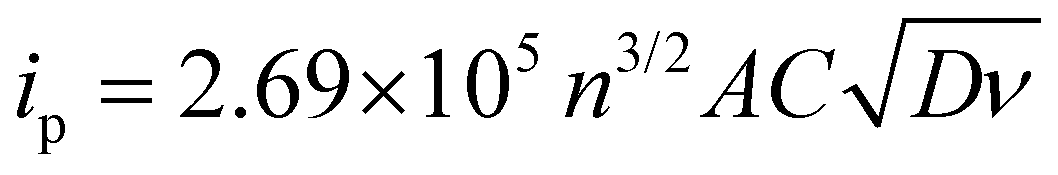 | (1) |
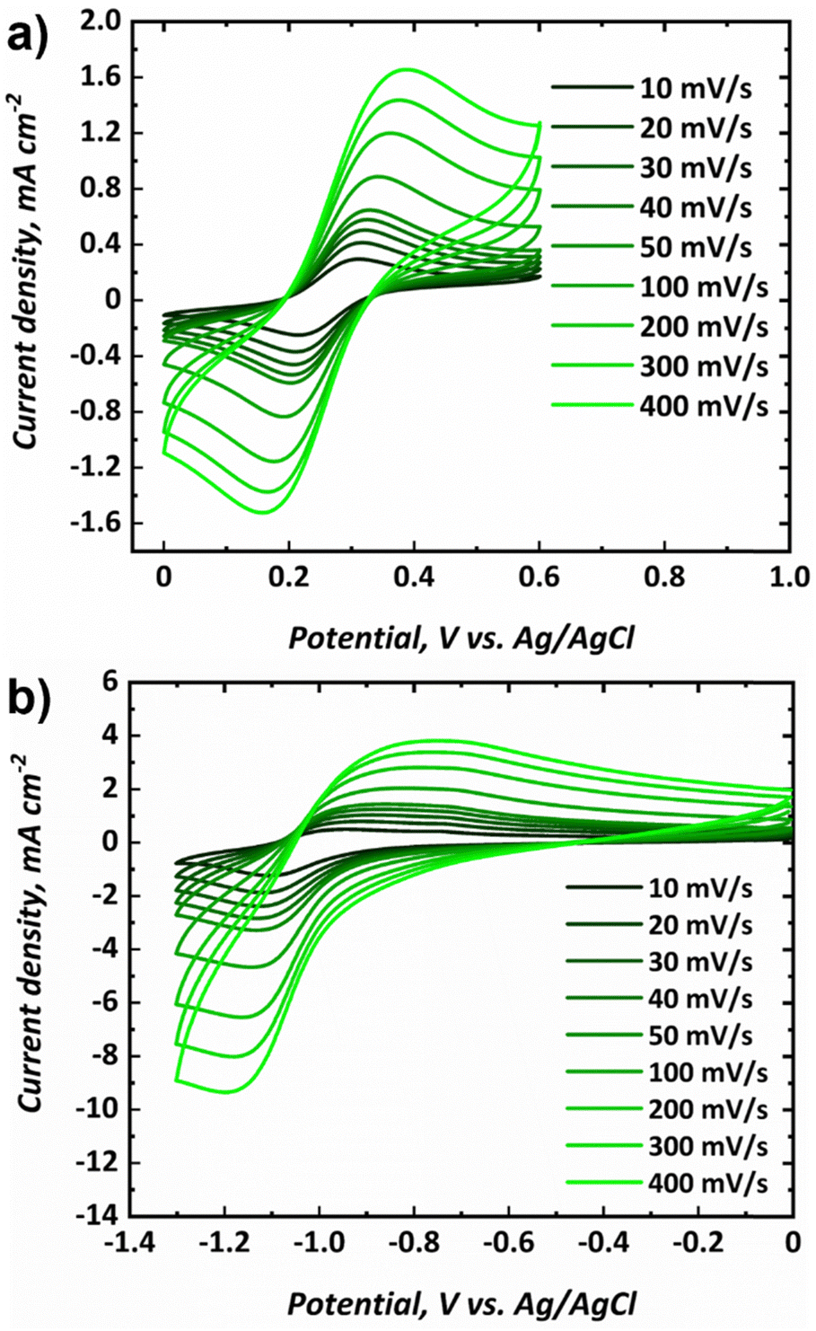 | ||
| Fig. 3 Cyclic voltammograms at various scan rates for the (a) posolyte (0.25 M Na4[Fe(CN)6], 0.25 M K4[Fe(CN)6], 1.00 M NaCl) and the (b) negolyte (0.50 M FeCl3, 1.00 M BIS-TRIS, 2.50 M NaOH) used in this study. | ||
The formal redox potential for the negolyte was shown to be −1.02 V (vs. Ag/AgCl), corresponding to −0.813 V (vs. SHE). This formal potential is less negative than the two Fe-BIS-TRIS reports to date (−1.11 V vs. Ag/AgCl).41,42 At a scan rate of 10 mV s−1, the uncompensated peak-to-peak separation for the negolyte redox couple was larger, at 161 mV. This value implies that the redox processes are appreciably limited by kinetics, and not solely diffusion. Thus, the Randle-Sevcik equation is unlikely to yield meaningful diffusion coefficients and is not applied here. It is worth noting that the Fe-BIS-TRIS complex recently explored in literature41,42 was formed from iron(III) sulphate, rather than from iron(III) chloride used here. Moreover, the literature complex was formed with a potassium counter-ion, whereas a sodium counter-ion is present here. Interestingly, the redox potential reported in this work matches more closely the previous Fe-TEOA reports, which suggests structural similarities between the complexes formed.25,31
Charge–discharge cycling
Charge–discharge cycling was performed for the selected all-soluble, all-iron RFB in both FT (using a graphite felt) and FO (using a carbon paper) configurations, at 10 mA cm−2 and 40 mA cm−2. The upper and lower cut-off voltages of 1.60 V and 0.50 V, respectively, were selected based on previous literature reports.31Fig. 4 shows the charge–discharge cycling behaviour at 10 mA cm−2 for the FT (Fig. 4a) and FO (Fig. 4b) configurations, as well as the plot of both capacity and the normalised capacity retention with respect to cycle number. It can be observed that the activation overpotential is lower in the FO system, with an onset charge potential of ca. 1.20 V, as opposed to ca. 1.30 V for the FT system. This is thought to stem from the greater inherent electrochemical activity of carbon papers vs. graphite felt materials, as observed in the all-vanadium system, accentuated by the heat-treatment activation in the carbon paper case. It should be noted here that heat-treatment of the graphite felt in the FT case would likely reduce this difference, but was not adopted in this work since the vast majority of all-soluble, all-iron FT systems in literature (Table 1) did not include heat-treatment of graphite felt electrodes.54 Most significantly, it is apparent that the capacity retention of the FO system is far superior to that of the FT system at 10 mA cm−2, the latter demonstrating a drop to ca. 65% of its original capacity after only six cycles. Over the respective time periods displayed in the Fig. 4 plots, the FO system broadly retains its capacity, demonstrating ca. 12 A h L−1 throughout, which represents ca. 90% electrolyte utilisation of this 0.5 M solution and is greater than the initial discharge capacity of the FT system (ca. 11 A h L−1, ∼82% electrolyte utilisation).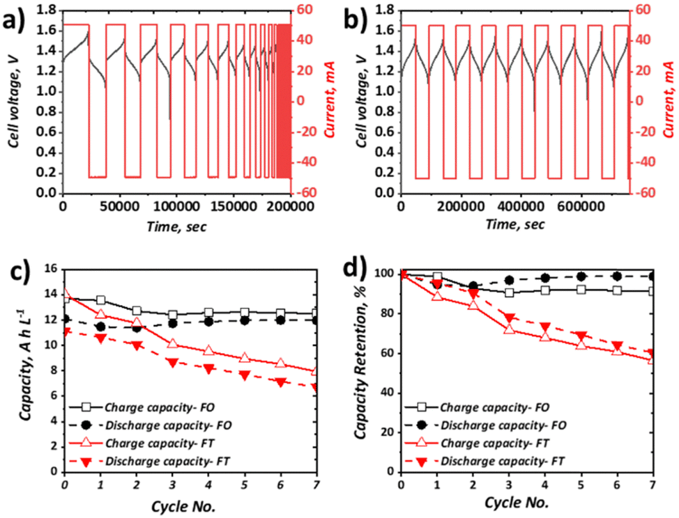 | ||
| Fig. 4 Charge–discharge behaviour at 10 mA cm−2 and 50 mL min−1 of 5 cm2 full cells containing 0.25 M Na4[Fe(CN)6], 0.25 M K4[Fe(CN)6], 1.00 M NaCl as the posolyte and 0.50 M FeCl3, 1.00 M BIS-TRIS, 2.50 M NaOH as the negolyte, with (a) FT configuration (25 mL posolyte and 25 mL negolyte) and (b) FO configuration (50 mL posolyte and 50 mL negolyte). Plots of (c) capacity and (d) capacity retention for each configuration for charge and discharge. | ||
Capacity loss in these systems can arise from several factors. In many organic systems, the redox active species themselves may be highly reactive and therefore give rise to unwanted side reactions,55,56 leading to ligand modification or decomposition. With regards to this study, recent work has shown that the posolyte is likely stable, even at high pH values33 (here pH is moderate at <10). Conversely, there is less understanding of the stability of the negolyte Fe-BIS-TRIS complexes, particularly at largely negative potentials. Indeed, in recent cyclic voltammetric studies, if insufficient ligand is present, Fe-TEOA and Fe-BIS-TRIS have been reported to exhibit reduction from Fe(II) to Fe(0) below −1.3 V (vs. Ag/AgCl).41,42 Aside from active species decomposition, there is also the possibility of side-reactions not directly associated with the active species, but instead due to the oxidation or reduction of free ligands, which would be accompanied by a concomitant loss of coulombic efficiency (CE). Moreover, the supporting electrolyte may also exhibit redox instability. For example, it has been shown that at high pH, the Fe(III)/Fe(II)-CN couple falls outside the electrochemical stability window (ESW) of water. However, with regards to this study that uses a 1.00 M NaCl supporting electrolyte at the relatively low pH of 9.4, it is thought that the oxygen evolution reaction (OER) is unlikely the dominant contributing factor to capacity fade witnessed in the FT cell.
Another major contributor to capacity loss is cross-over, which is the overarching term used to describe species transition from one electrolyte to the other through the membrane of the cell. This may come in the form of active species cross-over, supporting electrolyte cross-over and/or the cross-over of the bulk solvent. The driving forces for such transport can be diffusive (concentration difference), convective (pressure difference), or migratory (electrical potential difference). Although it has been shown through UV-Vis and ICP-OES measurements that the cross-over of metal–ligand complexes (such as Fe-CN and Fe-TEOA) is 15–68 times less than that of non-complexed vanadium and iron species,40 these H-cell measurements under no current flow do not accurately reflect cross-over during flow battery operation. Indeed, at OCV, the migratory driving force is missing, which may well be a dominant factor in capacity loss associated with cross-over during charge–discharge cycling.
Evidently, one or more of the processes contributing to capacity loss is exacerbated in the FT configuration vs. the FO configuration. Given the low activation overpotential, observed as a lower initial charging voltage, and the lower ohmic potential associated with a thinner electrode, it is expected that the total overpotential experienced during charge and discharge at a given SOC is likely lower in the FO than in the FT configuration. This is surmised to impact significantly on the observed behaviour of the Fe-CN/Fe-BIS-TRIS flow cell examined here, whereby the FT experiences significant capacity fade but the FO system appears to retain charge and discharge capacity appreciably at relatively low current density (10 mA cm−2), even over the resultant long-duration cycles.
When the current density was increased to 40 mA cm−2, which approximately represents the mean current density of all literature studies to date, appreciable capacity fade for both configurations was apparent (Fig. 5). In terms of discharge capacity, the absolute capacity reduced from ca. 8.3 A h L−1 to ca. 2.3 A h L−1 in 30 cycles (0.20 A h L−1 cycle−1) for the FT configuration and from ca. 11.5 A h L−1 to 6.5 A h L−1 (0.18 A h L−1 cycle−1) for the FO configuration. As shown in Fig. 5b this corresponds to capacity retentions of 26.6% and 53.2% for the FT and FO configurations, respectively. Very similar absolute capacity loss is observed over the same number of cycles, despite the longer charge and discharge times for the FO configuration (attributable to the use of a larger electrolyte volume). This observation suggests that the dominant capacity loss mechanism is related to charge–discharge behaviour, as opposed to self-discharge cross-over that would be expected to increase appreciably with longer charge–discharge times. This is also consistent with negligible cross-over of Fe-BIS-TRIS detected by ICP-OES analysis of an open-circuit H-cell, although the cross-over of Fe-CN from the positive half-cell to the negative half-cell cannot be ruled out. It is also worth noting that the capacity does not plateau after 20 cycles, as seen by Gong et al. in their Fe-CN/Fe-TEOA system,31 which was attributed to cross-over and membrane fouling. Moreover, capacity loss is greater than in the similar Fe-CN/Fe-BIS-TRIS system seen in recent work by Shin et al. which is thought to be due to differences in the electrolyte formulations (detailed in Table S4, ESI†). Nevertheless, capacity fade is significant in both cases and may be due to electroosmotic drag of active species across the membrane, driven by potential gradients that provide a greater driving force than concentration or pressure differences experienced in open-circuit set-ups.
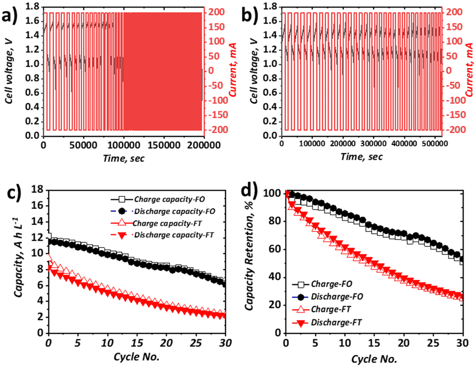 | ||
| Fig. 5 Charge–discharge behaviour at 40 mA cm−2 and 50 mL min−1 of 5 cm2 full cells containing 0.25 M Na4[Fe(CN)6], 0.25 M K4[Fe(CN)6], 1.00 M NaCl as the posolyte and 0.50 M FeCl3, 1.00 M BIS-TRIS, 2.50 M NaOH as the negolyte, with (a) FT configuration (25 mL posolyte and 25 mL negolyte) and (b) FO configuration (50 mL posolyte and 50 mL negolyte). Plots of (c) capacity and (d) capacity retention for each configuration for charge and discharge. | ||
In the FO case, the capacity fade is significantly greater than that observed at 10 mA cm−2. At the lower current density, the discharge capacity retention after six cycles was 99%, whereas at the higher current density, it was 93%, which also supports the assertion that the dominant capacity loss mechanism is related to overpotential rather than self-discharge. Moreover, the capacity loss in the FO configuration continues for at least 30 cycles without coming to a plateau.
Indeed, the exact nature of the capacity loss mechanisms in each case requires further examination, which is the focus of on-going work. From the direct comparison of the two set-ups, and the observation that the capacity loss is reduced when increasing current density in the FT configuration but increased when increasing current density in the FO configuration, it is clear more research should be carried out to better understand the impact of cell configuration on battery performance and durability.
Although the performance of this flow battery is not optimised, there are clear differences between both the onset charging potential and the capacity retention observed when investigating the same electrolyte with the same operating conditions, but with different cell configurations. Moreover, the behaviour witnessed across these two configurations sheds light on the underlying dominant mechanism leading to capacity loss in this newly investigated all-soluble, all-iron electrolyte.
Polarisation curve analysis
The polarisation curves and power densities at 100% SOC for the FT and FO configurations are shown in Fig. 6a and b, respectively. The maximum power density delivered by the FT cell was 125 mW cm−2, which represents ca. 60% of the closest literature equivalent.41 On the other hand, with the same electrolyte formulation, the maximum power density for the FO cell was 170 mW cm−2, which represents a 36% performance gain vs. the FT configuration. It is important to note that this value represents ca. 80% of the closest literature equivalent.41 The discrepancy likely results from the use of a thinner Nafion® 212 membrane in the literature, whereas thicker Nafion® 117 is used here, giving rise to greater ohmic losses and a lower maximum power density.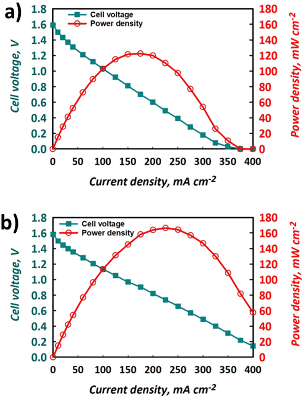 | ||
| Fig. 6 Polarisation and power density curves for the same electrolytes used to produce data shown in Fig. 4 and 5 using (a) FT configuration and (b) FO configuration, at nominally 100% SOC with electrolytes flowing at 50 mL min−1. | ||
The polarisation curves demonstrate that the use of a FO cell configuration can enhance the accessible maximum power density, which is thought to be due to the lowering of overpotentials in the system. Indeed, the gradient of the slope of the section of the polarisation curve that is dominated by ohmic losses is less negative for the FO (Fig. 6b) than the FT (Fig. 6a) configuration. This implies that the ohmic polarisation experienced in the FT cell, which contains three macroscopic felts (at 35% compression), is appreciably larger than that experienced in the FO set-up that contained a carbon paper with a thickness less than 300 μm. This is likely a convolution of the greater path length associated with current collection in the former case and a small increase in contact resistance, given the use of multiple separate pieces of graphite felt. Decreased mass transport loss in the thinner carbon paper is also possible, allowing the FO cell to perform at higher current densities and deliver the greater maximum power density. Indeed, the minimisation of transport losses in thin carbon paper compared to porous felt electrodes has been reported elsewhere when examining aspects such as pore diffusion.57 Nevertheless, to fully deconvolute these contributions to performance increase, the use of EIS is recommended, although this is beyond the scope of this work.
Efficiencies and self-discharge
It is important to consider the performance of RFBs at a range of current densities, given the variable loads experienced by EES technologies deployed in the field.58 The coulombic, voltage, and energy efficiencies of our all-soluble, all-iron system in the FT and the FO configurations are shown in Fig. 7a–c and the OCV as a function of time is shown in Fig. 7d, displaying the self-discharge characteristics of the two set-ups.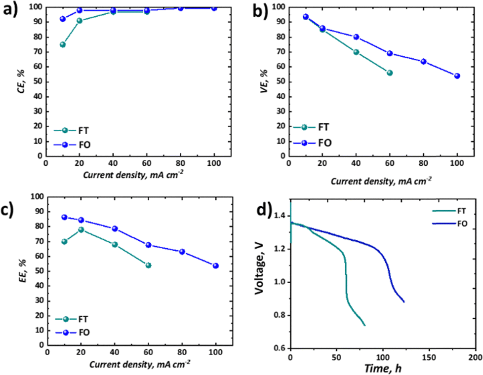 | ||
| Fig. 7 A comparison between flow-through (FT) and flow-over (FO) configurations in terms of key metrics (a) coulombic efficiency; (b) voltage efficiency; (c) energy efficiency; and (d) self-discharge performance at 50% of the practical SOC (estimated based on accessible charge capacity). | ||
As widely observed in VRFBs, there is a decrease in CE observed at lower current densities, resultant from the long charge–discharge times and significant cross-over of active species. It should be noted that here this loss is not recoverable, as unlike VRFBs, the iron-based electrolyte system is not readily corrected by electrochemical balancing.59 Nevertheless, once a current density of 40 mA cm−2 or greater is used, CE exceeds 95%. Upon attempting to run the FT cell at current densities of 80 mA cm−2 or above, the overpotentials were too high to observe an appreciable capacity without reaching the cut-off voltages. Therefore, for these higher current densities only data collected from experiments using the FO cell are presented (Fig. 7a–c). In terms of voltage efficiency (VE), the expected trend of decreasing VE with increasing current density was observed (Fig. 7b). It is worth noting, however, that the slope of this decline is appreciably less in the case of the FO cell, supporting the polarisation curve analysis which demonstrates that this design allows higher current densities to be accessed. As a confluence of these two efficiencies, the energy efficiency (EE) of the FO system outperforms that of the FT system, at least in this specific case, for all current densities, although it is a marginal difference at the low current density of 20 mA cm−2.
Importantly, as shown in Table 1, there are many cases of recent work on all-soluble, all-iron RFBs that have only reported the performance and durability of their electrolyte formulations in FT configurations. Indeed, given the high machining costs associated with the manufacture of this component from graphite, there are compelling reasons to use a FT configuration in both laboratory research and at the industrial scale. However, it is clear from the performance of the Fe-CN vs. Fe-BIS-TRIS RFB reported in this work that both performance and durability have been substantially improved by switching from the simpler FT cell to a FO configuration. Moreover, a lot of research is on-going to optimise the flow field design to further enhance performance in FO cells.60,61 It is therefore the authors’ recommendation that, in the fledgling domain of all-soluble, all-iron RFBs, researchers should consider testing their novel formulations in several types of cells and flow fields. In some cases, access to such cell hardware may create an impediment, though collaboration with other institutions may alleviate this issue.
The self-discharge performance of the two configurations might have been expected to be more similar than it is shown to be in Fig. 7d, given nominally the same flow rate, membrane material, and active area across the two configurations. Despite an initial period with similar voltage decline (until ca. 24 h), a secondary more pronounced drop in voltage ensues only in the FT case. The voltage associated with the FO cell instead continues a steady decline at the same rate until a precipitous drop at ca. 100 h, whereas the FT cell has a two-stage decline before reaching a precipitous drop after only ca. 60 h. Whereas other performance differences might be explained by differences in overpotentials across the two cells, here the cells are operating at OCV with continuous flow of electrolyte. The authors therefore hypothesise that despite similar flow rates produced by peristaltic pumps in the two systems, the actual residence time for the active species at the membrane is greater in the FT than the FO cell. The thicker, porous electrode cavity in the FT case has an estimated volume of 3.25 cm3 based on the cell hardware dimensions and the estimated compression level of the gaskets used. In contrast, the thin cavity of the FO case is estimated to be 0.125 cm3. Therefore, the residence time in the vicinity of the membrane will be much shorter in the FO case. Moreover, the pressure-driven laminar flow through the thicker porous felt is expected to experience an appreciable velocity gradient from the flow channel to the membrane interface. This boundary layer effect, which leads to lower velocities near solid surfaces, could further increase the actual residence time of species reaching the membrane in the FT case relative to the FO case, which has an open flow field and paper electrode, as it has previously been discussed in the literature.46,62,63 This hypothesis requires further investigation to better establish the mechanisms by which active species cross-over occurs in single-cell laboratory testing of all-soluble, all-iron chemistries. This may be achieved by dynamic ex situ cross-over experiments or by means of online analysis of active species cross-over in each of the two configurations. This phenomenon is only detected here as both cells were employed in this study.
Despite not being the highest-performing all-soluble, all-iron RFB system, the electrolytes chosen for this study represent an illustrative example of how testing novel chemistries should be carried out in both “flow-through” and “flow-over” configurations. At low current density (10 mA cm−2), for example, this chemistry could be seen as highly competitive with the incumbent vanadium technology, as it demonstrates high capacity retention (∼100%) over 9 days with high EE of ∼86% in the “flow-over” configuration. Nevertheless, if one were to take the parasitic pumping losses into account, one may choose to scale-up a “flow-through” configuration to avoid the pressure drop associated with an interdigitated flow field. When the performance in the “flow-through” cell is assessed, the significantly lower capacity retention (∼60% over 2 days) and EE (70%) are less compelling.
It should be stated that, although in this case the FO cell was shown to outperform the FT cell in terms of its lower discharge capacity decay, higher maximum power density, greater efficiencies at all current densities and lesser self-discharge, this may not be the case for all formulations and does not account for the parasitic losses associated with the extra pumping required,64 which would be reflected in an overall round-trip efficiency. The authors recommend that both cell configurations be used to better understand the performance and durability of future all-soluble, all-iron systems.
Experimental
Materials
Sodium ferrocyanide decahydrate (Na4Fe(CN)6·10H2O, ≥98%), potassium ferrocyanide (K4Fe(CN)6·3H2O, ≥98%), sodium chloride (NaCl, ≥99%), sodium hydroxide (NaOH, ≥98%), iron(III) chloride (FeCl3, ≥97%), and bis(2-hydroxyethyl)aminotris(hydroxymethyl) methane (BIS-TRIS, ≥98%) were purchased from Sigma-Aldrich (USA). All solutions were prepared in deionised water (>18.2 MΩ cm). Carbon paper (Sigracet 39AA, 280 μm thickness, pore size 43 μm) was purchased from Ion Power, Inc. (USA) and graphite felt (GFD EA 4.65, 4.65 mm thickness) was purchased from SGL Carbon (Germany). Nafion® membrane was purchased either from Ion Power, Inc. or Fuel Cell Store (USA).Electrolyte preparation
Electrolytes were freshly produced at appropriate volumes for each form of testing. For example, for charge–discharge cycling, 100 mL each of posolyte and negolyte were formulated, providing sufficient volume for 2–4 tests. In the case of the posolyte, 100 mL was made by simple room-temperature mixing of 12.10 g of Na4Fe(CN)6·10H2O (25.0 mmol), 10.56 g of K4Fe(CN)6·3H2O (25.0 mmol) and 5.84 g of NaCl (100 mmol) in deionised water. 100 mL of negolyte was made by first dissolving 10.00 g of NaOH (250 mmol) in deionised water at room temperature, to which 20.92 g of BIS-TRIS (100 mmol) was added. Once dissolved, 8.11 g of FeCl3 (50 mmol) was added dropwise resulting in a solution with an iron concentration of 0.5 M.Solubility testing
A 100 mL posolyte solution, consisting of 50:50 Na4[Fe(CN)6]:K4[Fe(CN)6], at a nominal iron concentration of 2.00 M was made by room-temperature mixing in deionised water. The mixture was subjected to ultrasonication at a frequency of 80 kHz for 10 min in a water bath programmed to maintain a temperature of 25 °C. A separate 100 mL solution was similarly made but with the inclusion of 1.00 M NaCl. A 100 mL saturated negolyte solution, comprising a 1:2:5 ratio of FeCl3:BIS-TRIS:NaOH, at a nominal iron concentration of 1.50 M was made, at room temperature, as described in the electrolyte preparation section.
A Cary 60 UV-Vis spectrometer (Agilent Technologies) was used for spectroscopic analysis of the system. First a calibration curve was established using known concentrations of each electrolyte. In the case of the posolyte, the absorption observed at 325 nm was used for quantification and for the negolyte, the absorption observed at 460 nm was used. Dilution with de-ionised water was employed to ensure measured absorbance remained below unity, with dilution factors of 1000× and 10× used for the posolyte and negolyte, respectively. All measurements were made in triplicate.
Density and viscosity
An automatic kinematic viscometer (SVM 3001, Anton Paar, Austria), was used to measure the dynamic viscosity and density of the electrolyte liquids (following standard test method ASTM D7042-21a) and their kinematic viscosities were calculated from these values.pH and ionic conductivity
The pH of the electrolyte solutions was measured using a FP20 FiveEasy Plus pH/mV benchtop meter (Mettler Toledo, UK), calibrated using three certified buffers with pHs of 4, 7 and 10. All data presented here are averages of three replicate tests conducted at 20 °C. The ionic conductivity of the electrolyte solutions was measured using an EC 71 Sens ION ionic conductivity meter (Hach, US), calibrated using three solutions of known ionic conductivity (147 μS cm−1, 1413 μS cm−1, and 12.88 mS cm−1). All data presented here are averages of three replicate tests.Cross-over studies
Static glass H-cells were set up using Nafion 117 and EPDM gaskets, with negolyte (0.50 M FeCl3, 1.00 M BIS-TRIS, 2.50 M NaOH) filling one chamber, and a 3.00 M KOH solution filling the other ‘deficient’ chamber. 0.1 mL samples were removed from the 'deficient' side after 1 h, 2 h, 3 h, 4 h, 68 h, 69 h, 70 h and 71 h. After removal from the H-cell chamber, each 0.1 mL sample was immediately added to 1 mL 3.00 mL KOH. For ICP-OES (5100, Agilent Technologies) analysis, 0.1 mL of sample was diluted to 1 mL by addition of de-ionised water, giving an overall dilution factor of 110.Cyclic voltammetry
A three-electrode setup was used for CV analysis to determine the electrochemical characteristics of the electrolyte. Glassy carbon (3 mm diameter), a Pt mesh (Pine Research Instrumentation, Inc. USA), and a silver/silver chloride (Ag/AgCl) electrode were used as the working, counter, and reference electrodes, respectively. A potentiostat (Autolab, Metrohm) was used to control the potential during CV experiments, using a potential window of 0.0 V to −1.3 V and 0 V to +0.6 V vs. Ag/AgCl to study the posolyte and negolyte redox reactions, respectively.Charge–discharge testing
All iron RFB charge–discharge experiments using the FT configuration were performed using an in-house cell, as described in previous work by the authors.65 This involved using an open-source 3D-printing platform, whereby the flow frame was designed in SolidWorks CAD software (Dassault Systèmes, France) to have a 5 cm2 active area, matching the commercial FO cell used in this work. The CAD file was exported as a stereolithography file to Cura (Ultimaker, the Netherlands) and printed using an Ultimaker S5 fused-deposition modelling 3D-printer. Other components, such as current collectors, O-rings, and gaskets were as previously described.65 Three pieces of graphite felt, untreated as in our previous work, were cut using bespoke metallic cutters and used on each side of a commercially available Nafion® 117 membrane (Fuel Cell Materials).All iron RFB charge–discharge experiments using the FO configuration were performed using a commercial flow cell (Fuel Cell Technology Inc., USA), with a 5 cm2 active area and an interdigitated flow field. A single piece of carbon paper (Sigracet 39AA, 280 μm thickness, pore size 43 μm), thermally treated at 500 °C in air for 1 h, was used on each side as electrodes. A Nafion 117 membrane (Ion Power, Inc.) was used to separate the two electrodes. In both configurations, the use of a cation-exchange membrane is thought to facilitate charge-compensation through the transport of alkali-ions (predominantly Na+ due to its smaller ionic radius).
Fig. 1 illustrates the schematic of the RFB flow cell. A dual-head peristaltic pump (BT100M, CRPUMP for FT and Masterflex, Cole Parmer for FO) was used to circulate the electrolyte solutions through the cell with flow rate of 50 mL min−1, calibrated by measuring the volume of electrolyte circulating per minute. 25 mL of each electrolyte was used in the case of the FT cell, whereas 50 mL of each electrolyte was used in the case of the FO cell. The membranes used were soaked for 4 h in 1 M NaCl in order to prepare the membrane for use in the flow cell. To remove oxygen from the electrolyte solution, nitrogen was continuously bubbled through the electrolytes for 30 min before the charge–discharge experiments, and a head of N2 was maintained during cycling. The charge–discharge experiments were performed at current densities in the range of 10 to 80 mA cm−2, using cut-off voltages of 1.60 V during charge, and 0.50 V for discharge. For the charge–discharge experiments, a potentiostat (Neware CT-408T-5V12A for FT and a BioLogic VSP with VMP3B-20 booster for FO) operating in galvanostatic mode was used. The RFB performance including voltage efficiency (VE), coulombic efficiency (CE), and energy efficiency (EE) were determined based on eqn (2)–(4):
| CE = Qd/Qc × 100% | (2) |
| VE = V(d,avg)/V(c,avg) × 100% | (3) |
| EE = CE × VE | (4) |
Polarisation curve analysis
For the polarisation experiment the SOC of the battery was adjusted to 100%, corresponding to an OCV of around 1.60 V. The galvanostatic polarisation was performed with a 30 second hold per step to obtain a steady state cell potential. The cell was recharged at 25 mA cm−2 to 100% SOC after each step in the polarisation. For the polarisation experiments, a potentiostat (BioLogic VSP with booster VMP3B-20) was used in both cases. In self-discharge experiments, the battery was at OCV while electrolyte at 50% SOC was circulated through the cell, and the cell voltage was monitored.Conclusion
This study marks the first side-by-side examination of the same all-soluble, all-iron chemistry in flow-through and flow-over cells, revealing substantial configuration-dependent differences that may extend to the performance analysis of other electrolytes such as vanadium- or organic-based systems. Our meticulous side-by-side comparative electrochemical testing revealed substantial differences in performance metrics when using identical all-soluble, all-iron electrolytes in flow-through versus flow-over configurations under almost identical operating conditions. The most prominent difference observed was a markedly more significant capacity fade exhibited by the flow-through cell, such that operation at 40 mA cm−2 was accompanied by a loss of 75% in discharge capacity after 30 cycles, whilst only 50% loss was seen for the analogous flow-over cell. Contrasting behaviour with respect to the effect of increasing current density across the two configurations also highlights the potential for different dominating degradation mechanisms in the two systems. Our findings show that while the flow-over configuration excels in energy efficiency, setting a new benchmark for all-soluble, all-iron systems, the more profound implication lies in how the choice of cell hardware significantly shapes the performance outcomes of these novel chemistries. Therefore, the inclusion of both flow-through and flow-over configurations in future explorations of all-iron RFBs is strongly recommended, and it is suggested that similar studies should be carried out in vanadium-based systems. Such an approach will provide a more comprehensive understanding of these systems, helping to optimise their design and operation. It is hoped that the insights gained in the study presented here will catalyse new research into how maximum power density, self-discharge time, capacity retention, and energy efficiency are impacted by the test cell used, and that this will provide motivation to explore both novel and typical electrolytes more holistically in this rapidly evolving field.Author contributions
JJB – conceptualisation, data curation, formal analysis, investigation, methodology, project administration, validation, writing – original draft; MP – data curation, formal analysis, investigation, methodology, validation, visualisation, writing – review & editing; HQNG – conceptualisation, investigation, methodology, writing – review & editing; HOC – investigation, visualisation, writing – review & editing; KT – investigation; PS – investigation; OI – project administration, resources, supervision, writing – review & editing; SG – resources, supervision, funding acquisition; PAAK – resources, funding acquisition, writing – review & editing, EPLR – funding acquisition, project administration, resources, supervision, writing – review & editing, PN – conceptualisation, project administration, resources, supervision, writing – review & editing.Conflicts of interest
There are no conflicts to declare.Acknowledgements
This work was supported by the Centre for Advanced Sustainable Energy (CASE) and the industrial partners, Shell Global Solutions Internal B.V., Seren AG, and Grants Electrical Services, as part of the AESIR project. CASE is funded through Invest NI's Competence Centre Programme which aims to transform the sustainable energy sector through business research. EPLR would like to thank the Natural Sciences and Engineering Research Council of Canada (NSERC) for funding on projects CREATE-495455-2017 and RGPIN-2018-03725.Notes and references
- P. Arévalo-Cid, P. Dias, A. Mendes and J. Azevedo, Sustainable Energy Fuels, 2021, 5366–5419 RSC.
- M. Resch, J. Bühler, B. Schachler, R. Kunert, A. Meier and A. Sumper, Int. J. Energy Res., 2019, 43, 337–357 CrossRef.
- A. Blakers, M. Stocks, B. Lu and C. Cheng, Prog. Energy, 2001, 3(2), 022003 CrossRef.
- IEA, Tracking Clean Energy Progress 2023, Paris, 2023.
- J. Girschik, L. Kopietz, M. Joemann, A. Grevé and C. Doetsch, Chem. Ing. Tech., 2021, 93, 523–533 CrossRef CAS.
- L. Tang, P. Leung, M. R. Mohamed, Q. Xu, S. Dai, X. Zhu, C. Flox, A. A. Shah and Q. Liao, Electrochim. Acta, 2023, 437, 141460 CrossRef CAS.
- Y. Zhang, L. Liu, J. Xi, Z. Wu and X. Qiu, Appl. Energy, 2017, 204, 373–381 CrossRef CAS.
- A. Z. Weber, M. M. Mench, J. P. Meyers, P. N. Ross, J. T. Gostick and Q. Liu, J. Appl. Electrochem., 2011, 41, 1137–1164 CrossRef CAS.
- K. E. Rodby, R. L. Jaffe, E. A. Olivetti and F. R. Brushett, J. Power Sources, 2023, 560, 232605 CrossRef CAS.
- S. E. Waters, B. H. Robb, M. P. Marshak and M. P. Marshak, ACS Energy Lett., 2020, 5, 1758–1762 CrossRef CAS.
- S. Suresh, M. Ulaganathan, N. Venkatesan, P. Periasamy and P. Ragupathy, J. Energy Storage, 2018, 20, 134–139 CrossRef.
- Z. Li and Y. C. Lu, Nat. Energy, 2021, 6, 517–528 CrossRef CAS.
- S. S. Shree, J. N. Law, C. E. Tripp, D. Duplyakin, E. Skordilis, D. Biagioni, R. S. Paton and P. C. John, Nat. Mach. Intell., 2022, 1–13 Search PubMed.
- J. Luo, B. Hu, M. Hu, Y. Zhao and T. L. Liu, ACS Energy Lett., 2019, 4, 2220–2240 CrossRef CAS.
- M. Pahlevaninezhad, P. Leung, P. Q. Velasco, M. Pahlevani, F. C. Walsh, E. P. L. Roberts and C. Ponce de León, J. Power Sources, 2021, 500, 229942 CrossRef CAS.
- J. D. Milshtein, A. P. Kaur, M. D. Casselman, J. A. Kowalski, S. Modekrutti, P. L. Zhang, N. Harsha Attanayake, C. F. Elliott, S. R. Parkin, C. Risko, F. R. Brushett and S. A. Odom, Energy Environ. Sci., 2016, 9, 3531–3543 RSC.
- C. Roth, J. Noack and M. Skyllas-Kazacos, Flow Batteries, Wiley-VCH, 2023, vol. 6 Search PubMed.
- E. Sánchez-Díez, E. Ventosa, M. Guarnieri, A. Trovò, C. Flox, R. Marcilla, F. Soavi, P. Mazur, E. Aranzabe and R. Ferret, J. Power Sources, 2021, 481, 228804 CrossRef.
- L. W. Hruska and R. F. Savinell, J. Electrochem. Soc., 1981, 128, 18–25 CrossRef CAS.
- S. Yu, X. Yue, J. Holoubek, X. Xing, E. Pan, T. Pascal and P. Liu, J. Power Sources, 2021, 513, 230457 CrossRef CAS.
- B. S. Jayathilake, E. J. Plichta, M. A. Hendrickson and S. R. Narayanan, J. Electrochem. Soc., 2018, 165, A1630–A1638 CrossRef CAS.
- K. L. Hawthorne, J. S. Wainright and R. F. Savinell, J. Electrochem. Soc., 2014, 161, A1662–A1671 CrossRef CAS.
- Y. D. Chen, K. S. V. Santhanam and A. J. Bard, J. Electrochem. Soc., 1981, 128, 1460–1467 CrossRef CAS.
- J. G. Ibanez, C. Choi and R. S. Becker, J. Electrochem. Soc., 1987, 134, 3083–3089 CrossRef CAS.
- Y. H. Wen, H. M. Zhang, P. Qian, H. T. Zhou, P. Zhao, B. L. Yi and Y. S. Yang, Electrochim. Acta, 2006, 51, 3769–3775 CrossRef CAS.
- Y. H. Wen, H. M. Zhang, P. Qian, H. T. Zhou, P. Zhao, B. L. Yi and Y. S. Yang, J. Electrochem. Soc., 2006, 153, A929 CrossRef CAS.
- N. Arroyo-Currás, J. W. Hall, J. E. Dick, R. A. Jones and A. J. Bard, J. Electrochem. Soc., 2015, 162, A378–A383 CrossRef.
- C. Noh, Y. Chung and Y. Kwon, J. Power Sources, 2020, 466, 228333 CrossRef CAS.
- C. Noh, Y. Chung and Y. Kwon, Chem. Eng. J., 2021, 405, 126966 CrossRef CAS.
- C. Noh, Y. Chung and Y. Kwon, J. Power Sources, 2021, 495, 229799 CrossRef CAS.
- K. Gong, F. Xu, J. B. Grunewald, X. Ma, Y. Zhao, S. Gu and Y. Yan, ACS Energy Lett., 2016, 1, 89–93 CrossRef CAS.
- J. Luo, A. Sam, B. Hu, C. DeBruler, X. Wei, W. Wang and T. L. Liu, Nano Energy, 2017, 42, 215–221 CrossRef CAS.
- T. Páez, A. Martínez-Cuezva, J. Palma and E. Ventosa, J. Power Sources, 2020, 471, 228453 CrossRef.
- T. Páez, A. Martínez-Cuezva, R. Marcilla, J. Palma and E. Ventosa, J. Power Sources, 2021, 512, 230516 CrossRef.
- M. Lenninger, N. Aguilo-Aguayo and T. Bechtold, J. Electroanal. Chem., 2018, 830–831, 50–55 CrossRef CAS.
- A. Lê, D. Floner, T. Roisnel, O. Cador, L. Chancelier and F. Geneste, Electrochim. Acta, 2019, 301, 472–477 CrossRef.
- S. Sreenath, N. K. Sharma and R. K. Nagarale, RSC Adv., 2020, 10, 44824–44833 RSC.
- M. Shin, C. Noh, Y. Chung and Y. Kwon, Chem. Eng. J., 2020, 398, 125631 CrossRef CAS.
- N. A. Currás, Development of an alkaline redox flow battery: from fundamentals to benchtop prototype, PhD thesis, The University of Texas, Austin, 2005, https://hdl.handle.net/2152/30510 Search PubMed.
- C. Noh, M. Shin and Y. Kwon, J. Power Sources, 2022, 520, 230810 CrossRef CAS.
- M. Shin, S. Oh, H. Jeong, C. Noh, Y. Chung, J. W. Han and Y. Kwon, Int. J. Energy Res., 2022, 46, 8175–8185 CrossRef CAS.
- M. Shin, C. Noh and Y. Kwon, Chem. Eng. J., 2023, 453 Search PubMed.
- M. D. R. Kok, A. Khalifa and J. T. Gostick, J. Electrochem. Soc., 2016, 163, A1408–A1419 CrossRef CAS.
- L. F. Arenas, C. Ponce de León and F. C. Walsh, J. Energy Storage, 2017, 11, 119–153 CrossRef.
- T. Davies and J. Tummino, J. Carbon Res., 2018, 4, 8 CrossRef.
- S. Maurya, P. T. Nguyen, Y. S. Kim, Q. Kang and R. Mukundan, J. Power Sources, 2018, 404, 20–27 CrossRef CAS.
- A. M. Pezeshki, R. L. Sacci, F. M. Delnick, D. S. Aaron and M. M. Mench, Electrochim. Acta, 2017, 229, 261–270 CrossRef CAS.
- P. Schröder, D. Obendorf and T. Bechtold, ChemElectroChem, 2019, 6, 3311–3318 CrossRef.
- A. J. Esswein, J. Goeltz and D. Amadeo, US20140051003A1, 2014.
- D. Reber, J. R. Thurston, M. Becker and M. P. Marshak, Cell Rep. Phys. Sci., 2023, 4, 101215 CrossRef CAS.
- C. Zhang, T. S. Zhao, Q. Xu, L. An and G. Zhao, Appl. Energy, 2015, 155, 349–353 CrossRef CAS.
- J. L. Barton, J. D. Milshtein, J. J. Hinricher and F. R. Brushett, J. Power Sources, 2018, 399, 133–143 CrossRef CAS.
- Y. Song, X. Li, C. Yan and A. Tang, J. Power Sources, 2020, 480, 229141 CrossRef CAS.
- O. Nibel, S. M. Taylor, A. Pătru, E. Fabbri, L. Gubler and T. J. Schmidt, J. Electrochem. Soc., 2017, 164, A1608–A1615 CrossRef CAS.
- T. E. Society and A. Manuscript, JECS.
- B. Huskinson, M. P. Marshak, C. Suh, S. Er, M. R. Gerhardt, C. J. Galvin, X. Chen, A. Aspuru-Guzik, R. G. Gordon and M. J. Aziz, Nature, 2014, 505, 195–198 CrossRef CAS PubMed.
- K. M. Lisboa, J. Marschewski, N. Ebejer, P. Ruch, R. M. Cotta, B. Michel and D. Poulikakos, J. Power Sources, 2017, 359, 322–331 CrossRef CAS.
- L. Deguenon, D. Yamegueu, S. Moussa Kadri and A. Gomna, J. Power Sources, 2023, 580, 233343 CrossRef CAS.
- N. Poli, M. Schäffer, A. Trovò, J. Noack, M. Guarnieri and P. Fischer, Chem. Eng. J., 2021, 405, 126583 CrossRef CAS.
- K. Yaji, S. Yamasaki, S. Tsushima, T. Suzuki and K. Fujita, Struct. Multidiscip. Optim., 2018, 57, 535–546 CrossRef.
- C. H. Chen, K. Yaji, S. Yamasaki, S. Tsushima and K. Fujita, J. Energy Storage, 2019, 26, 100990 CrossRef.
- H. Park, G. Kwon, H. Lee, K. Lee, S. Y. Park, J. E. Kwon, K. Kang and S. J. Kim, Proc. Natl. Acad. Sci. U. S. A., 2022, 119, 1–9 Search PubMed.
- S. Kuperman, R. Ronen, Y. Matia, A. Zigelman, M. E. Suss and A. D. Gat, Flow, 2022, 2, E11 CrossRef.
- W. Xiao and L. Tan, Renewable Energy, 2019, 133, 1445–1454 CrossRef CAS.
- H. O’Connor, J. J. Bailey, O. M. Istrate, P. A. A. Klusener, R. Watson, S. Glover, F. Iacoviello, D. J. L. Brett, P. R. Shearing and P. Nockemann, Sustainable Energy Fuels, 2022, 6, 1529–1540 RSC.
- N. Aguiló-Aguayo and T. Bechtold, J. Electrochem. Soc., 2018, 165, A3164–A3168 CrossRef.
- S. Sreenath, N. K. Sharma and R. K. Nagarale, RSC Adv., 2020, 10, 44824–44833 RSC.
- P. Schröder, N. Aguiló-Aguayo, D. Obendorf and T. Bechtold, Electrochim. Acta, 2022, 430, 2–10 CrossRef.
Footnote |
| † Electronic supplementary information (ESI) available. See DOI: https://doi.org/10.1039/d4ya00179f |
| This journal is © The Royal Society of Chemistry 2024 |