
 Open Access Article
 This Open Access Article is licensed under a
 Creative Commons Attribution 3.0 Unported Licence
Soft carbon in non-aqueous rechargeable batteries: a review of its synthesis, carbonization mechanism, characterization, and multifarious applications
Shuvajit
Ghosh
,
Mohammad
Zaid
,
Jyotirekha
Dutta
,
Monira
Parvin
and
Surendra K.
Martha
 *
*
Department of Chemistry, Indian Institute of Technology Hyderabad, Kandi, Sangareddy, 502284, Telangana, India. E-mail: martha@chy.iith.ac.in
First published on 13th May 2024
Abstract
Soft carbon is a special class of carbon materials having tunable physical properties that makes it suitable for various battery applications. The precursors containing large polyaromatic hydrocarbons undergo mesophase formation via complex organic rearrangements, which endows soft carbon with unique attributes. Soft carbon is considered an ideal and upscalable matrix for Si-based anodes due to its non-overlapping potential zone of lithiation with Si/SiOx, interfacial cohesion, structural stability, and spatial connection. It is considered superior to other carbonaceous materials in confining polysulfides and enabling a higher loading of sulphur in Li–S batteries. It is the best anode for K-storage because of its ideal diffusion/adsorption balance, a good matrix for Na storage due to its enormous expandability, and an emerging material for anion storage as it contains graphitic microdomains. Soft carbon behaves as a multifunctional coating agent, capable of mitigating the poor electronic conductivity of polyanionic cathodes, alleviating interfacial instabilities of graphite anodes, and providing high voltage protection to spinel oxide and anion-storing cathodes. It is also employed in three-dimensional carbon fiber electrodes, where it plays multifaceted roles as a binder, conductive additive, and coating agent. Further, carbon-based current collectors can be prepared from soft carbon. In summary, this review summarizes all the attributes of soft carbon for use in rechargeable batteries.
1. Introduction
The electrification of everything has been suggested as a possible panacea for the global climate crisis.1 The source of electricity is projected to be the renewables, as these sources are generally decarbonized, greener, and more sustainable than currently utilized non-renewables.2 However, the intermittent nature of renewables entails the need for the complementary storage of the generated energy to ensure an uninterrupted supply of electricity. Unfortunately, the year-round storage of energy at the utility-scale is a herculean task and poses a plethora of challenges.3,4 The task is so onerous that the existing system of the electric grid utilizes the electricity produced instantly, avoiding the difficulties of storing energy between production and consumption.5 However, developments in building energy-storage platforms have progressed steadily over the years and has experienced great leaps forward in the last decade. Rechargeable batteries are at the vanguard of this revolution. In particular the market introduction of lithium-ion batteries (LIBs) in the 1990s changed the landscape of the energy-storage sector.6 In the absence of competitive technologies, LIBs have established a monopoly in the portable electronics market. Nonetheless, the future requirements of batteries are not only confined to handheld electronic gadgets but are also widespread in grids, land transportation, aviation, household supply, wearable biomedicals, etc.7 Keeping abreast of the times, innovative technologies such as lithium–sulfur, sodium-ion, redox-flow, lithium–metal, and dual-carbon batteries have also emerged as more suitable and meticulously crafted alternatives for specific applications.8,9 These next-generation LIB analogs may surpass conventional LIBs in terms of sustainability, recyclability, safety, and cost. However, the superior package of LIBs’ electrochemical output still represents the state-of-the-art for upcoming technologies to follow.10 Therefore, considerable efforts have been devoted to improving the electrochemical properties such as the capacity retention, cycle life, cycling efficiencies, and voltage fade of prospective future batteries using low-cost materials and sustainable methods.11 Even LIBs are under continuous scrutiny for improvements beyond their current performance level so that they can reach new paradigms of high energy (300 W h kgpack−1) and long life (>5000 cycles with 80% capacity retention).12Carbon is the most used material in rechargeable non-aqueous batteries.13 Historically, the breakthrough finding of Li-ion-storing properties in graphite led to the commercialization of LIBs. Graphite-based LIBs still lead the market. However, graphite is not a good choice for storing Na+ and K+, where disordered (hard and soft) carbons excel. Interestingly though, graphite can also store anions (PF6−, FSI−, TFSI−, etc.), which resulted in the discovery of dual-ion batteries (DIBs), or dual-graphite batteries (DGBs), way back in 1930s.14,15 Unfortunately, the system did not gain popularity, as most attention was focused on the excellent electrochemical performances of LIBs. In most common cases, LIBs contain a graphite anode and layered oxide/phosphate cathode. The conventional system functioning on both intercalation-type cathode and anode materials can deliver a maximum energy density of 200–230 W h kgpack−1 depending on the cathode composition. In order to increase energy densities to >250 W h kgpack−1, the intercalation-type graphite anode must be substituted with conversion/alloying materials, like Si-based compounds. Moreover, energy densities beyond >250 W h kgpack−1 mandate the replacement of intercalation-type Ni-rich (Ni > 80%) layered oxide cathodes by conversion materials, such as metal fluorides and sulfur. Unfortunately, the conversion/alloying materials generally suffer from significant volume expansion, which shortens the cycle life. This issue can be mitigated by encapsulating the conversion/alloying material within a porous bulk that can buffer the volume expansion.16,17 Carbon is a natural choice in this aspect due to the ease of tuning its morphology, porosity, form factors, and flexibility.18 Carbon sculpted in three-dimensional foam and fibrous architectures can accommodate volume expansion as well as acts as the current collector. Another viable option to tackle the challenge is employing flexible binders with superior adhesive properties.19 Carbon can also be utilized as a binder to integrate conversion/alloying materials with the carbon matrix. On the other hand, phosphate-based intercalation cathodes (LiFePO4 and LiMn1−xFexPO4) are the safest choice for high-power batteries. The robust phosphate framework undergoes minimal volume changes during de/lithiation, offers faster ionic diffusion, and does not release oxygen when damaged.20 However the material fails drastically in the absence of a conductive coating due to its poor electronic conductivity (10−9–10−11 S cm−1). Carbonaceous materials, owing to their dual-ion–electron conducting nature, are perfect contenders for coating agent for non-oxide cathode materials with low electron conductivity (<10−7 S cm−1), such as phosphates, silicates, and vanadates.21 Similarly, intercalation-type niobate and titanate anodes are thermally safer alternatives to graphite to couple with phosphate cathodes in a high-power LIB pack under the circumstances of fast charging.22 Graphite undergoes severe lithium plating under elevated charge currents, compromising the safety of the LIB pack, while the niobate and titanate anodes are specially designed to withstand higher current rates without structural deterioration and lithium plating. However, the poor electronic conductivity (10−13 S cm−1 for titanates) can be taken care of by applying a carbon coating.23 Further, carbon materials have also found to be useful as a protective shield on graphite anodes, where surface heterogeneities and defects trigger electrolyte decomposition. Carbon coating alleviates the parasitic side reactions at the electrode–electrolyte interface (EEI), enhancing cycling (coulombic, voltage, and energy) efficiencies, and capacity retention.24 In short, carbon is used in multifarious applications in batteries, i.e., as an anode and cathode active material, as an anode and cathode coating agent, in the conductive additive–binder domain, and as a current collector.
Carbons that intercalate ions can be classified into two categories: ordered and disordered. First, ordered graphite is highly crystalline and possesses long-range order, where sp2-hybridized sheets stack along the c-axis to give rise to either the hexagonal AB sequence or the rhombohedral ABC sequence. The π-bond delocalization enables 103–104 S cm−1 of in-plane electronic conductivity along the ab-direction, whereas the weak cohesive van der Waals (VdW) force (16–17 kJ mol−1) creates an interlayer spacing of 3.35 Å along the c-direction, rendering space available for the easy intercalation of guest species.25 Moreover, the redox property of graphite is amphoteric, whereby both cations and anions can intercalate to form graphite-intercalation compounds (GICs).26 This is why graphite is useful as a cation-storing anode in LIBs and as an anion-storing cathode in dual-carbon batteries. Another important feature of graphite is its material density of >2 g cm−3, which transitions into tap density >1 g cm−3 for graphite electrodes, which is higher than that for disordered carbons (≤0.7 g cm−3). The Nobel Laureate Akira Yoshino recalls his efforts to replace the polyacetylene anode (material density: 1.2 g cm−3) with graphitic material for coupling with a LiCoO2 cathode in order to simultaneously fulfill the criteria of small size, lightweight, and energy dense. In his words, the graphitic material was the final piece of the jigsaw that led to the breakthrough discovery of the first rechargeable LIB.27 Second, disordered hard and soft carbons are better anodes for Na+ and K+ storage than ordered graphite. They do not contain an ordered arrangement of graphene sheets either along the in-plane ab-direction or along the c-direction of stacking. Their structure is a hybrid of graphitic and non-graphitic regions. It can be realized as sp2-hybridized graphene sheets oriented in short range to yield crystalline graphite-like microdomains crosslinked by sp3-hybridized linkers representing amorphous non-graphitic domains.28 Based on the conversion ability of non-graphitic regions into a graphitic arrangement, the categorization of hard and soft carbon was brought in. The strong crosslinking interaction resisting graphitization upon thermal treatment, even up to >2500 °C, is a classic feature of hard carbon, whereas the gradual transformation of weak crosslinking regions into graphitic domains beyond 2000 °C distinguishes soft carbon.29 The graphitizability, i.e., the extent of the graphitic domains over non-graphitic, is tunable depending on the applied temperature, which can be designated as the most attractive feature of soft carbon that cannot be offered by graphite or hard carbon. This feature renders unique attributes to soft carbon, such as electronic conductivity, mechanical strength, and porosity. The tweakability of such properties also assists in deriving optimizable soft carbon structures for tailor-made applications. Therefore, it can be useful for numerous applications in electrochemical energy-storage devices, like as a cation and anion storage matrix, as a cation and anion coating agent, as a binder, and so on.
There exist numerous excellent-quality and highly cited review articles in the literature centered on graphite anodes for LIBs, graphite cathodes for dual-ion batteries, hard and soft carbon anodes for SIBs and KIBs, applications of a particular morphology and topology of carbon (nanospheres, nanohollow, nano-onions, defect engineered, multiscale porosity, etc.) in batteries, progress of a specific form of carbon (graphene, graphene derivatives, quantum dots, fullerene, nanotubes, etc.) in energy applications, and the evolution of biomass-derived heteroatom-doped carbons as active materials.25,30–42 However, a focused review based on the unique attributes and ubiquitous utilizations of soft carbon in rechargeable batteries can hardly be found. This motivated us to produce a summary of the aforementioned topics that may provide comprehensive insights to the battery community in a single article. Therefore, this review aimed at representing the retrospective history and prospective future of soft carbon in rechargeable batteries (Scheme 1).
 | ||
| Scheme 1 Schematic illustration of the manuscript. | ||
2. Origin and molecular mechanism behind the unique properties of soft carbon
2.1. Molecular structure of the pitch precursors
Carbon-rich materials having a low content of heteroatoms (N, O, S, etc.) are the best precursors for soft carbon, such as petroleum pitch, coal tar pitch, few organic moieties, and coke. The weak crosslinking in these precursors means they become mobile at high temperature, thereby converting into graphite-like crystallites. Pitch from petroleum byproducts is the most popular, widely abundant, and vastly explored precursor of soft carbon.The molecular structure of pitch is a subject of debate due to the exceptional molecular diversity and the low solubility of its constituents. This conundrum has puzzled scientists for the last 50 years and several hypothesized structures have been put forward using advanced characterization tools. This changed though in 2020, when Chen et al. imaged the building blocks of pitch via non-contact atomic force microscopy (nc-AFM).43 They presented direct evidence of 30 large polyaromatic hydrocarbons (PAHs), as shown in Fig. 1a. Their study was carried on M50 pitch having 92.2 wt% carbon, a H/C ratio of 0.73, a softening point of 240 °C, a double bond equivalent (DBE) of 20 ± 8, and a density of 1.015 g cm−3. The chemical structures can be viewed as 6-membered rings, such as pyrene (C16H10), benzopyrene (C20H12), phenanthrene (C14H12), and benzophenanthrene (C18H12), and 5-membered rings, like non-conjugated fluorene (C13H10) and conjugated fluoranthene (C16H10) catacondensed to form aromatic cores in the range of 17–65 carbons (Fig. 1a). The compounds are rarely full aromatic, as all are attached to 2–3 linear aliphatic side chains and linkers, like methyl (–CH3), methylene (–CH2), and ethyl (–C2H5) mostly. The aromatic components (91% C and 69% H) dominate over the aliphatic (9% C and 31% H), which is a classic requisite for the transformation to soft carbon products. The key structural features were proposed to originate from a small aliphatic substituted pyrene group via a free-radical mechanism. Zhang et al., using high-resolution matrix-assisted laser desorption ionization (MALDI) time-of-flight (TOF) mass spectroscopy (MS), elucidated the subtle differences between the molecular structures of petroleum pitch (PP) and coal tar pitch (CTP).44 Their investigation revealed that PP comprises PAHs having a wider distribution of carbon number and DBEs than coal tar pitch, thereby representing more entangled structures. The major species of PP are high-carbon-number molecules with short aliphatic chains, where largely condensed small-carbon-numbered aromatic cores containing cyclopenta-fused rings and having few or no aliphatic chains exist in CTP. In short, CTP has a higher degree of unsaturation than PP. Wu et al. reached the same conclusion of a greater aromatic index in CTP than PP via systematic explorations using elemental analysis, solubility tests, FT-IR, XRD, 13C-NMR, and TOF-MS studies.45 In their report, the solubility test was used as an important parameter for pitch classification. The larger percentage of toluene insolubles (62.9% in CTP vs. 50.3% in PP) causes a higher softening point (293 °C for CTP vs. 261 °C for PP) and lower volatiles (29.5% in CTP vs. 37.7% in PP at 900 °C) in the case of CTP. The precursor with lower volatiles resulted in a better carbon yield (65.4% in CTP vs. 60.5% in PP at 1000 °C).
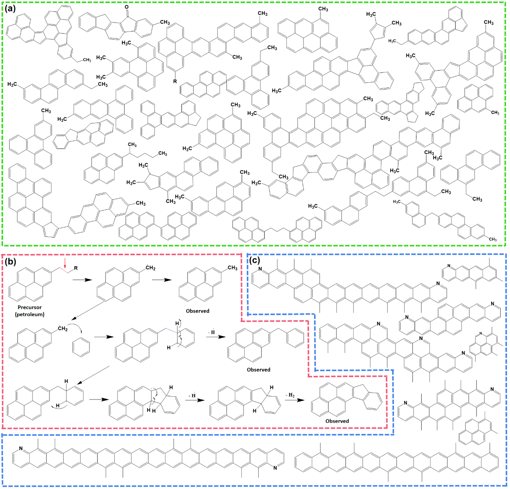 | ||
| Fig. 1 (a) Molecular constituents of M50 pitch detected using non-contact atomic force microscopy (nc-AFM). Inspired from ref. 42. (b) Example of a thermal fusion reaction during the carbonization of pitch. Redrawn from ref. 42. (c) Existing polyaromatic hydrocarbons during the carbonization of pitch at 560–670 °C. Redrawn from ref. 46. | ||
2.2. Thermochemical mechanism of the mesophase evolution
Pitch undergoes several physical and chemical changes when subjected to thermal treatments and transforms into an infusible polymer known as ‘coke’ at ≥1000 °C, before finally resulting in graphite at ≥2500 °C. At lower temperatures ≤300 °C, pitch softens at first, then with the gradual increase in temperature, it forms a partially ordered liquid-crystalline intermediate stage, called the ‘mesophase’.46 The formation of a mesophase is an important feature of the thermal polymerization of pitch precursors, and furnishes unique properties to the resulting soft carbon compared to carbons from other precursors synthesized at similar temperatures. Therefore, the molecular rearrangement behind this thermal polymerization has been thoroughly studied in the literature using advanced techniques, like MALDI-TOF-SIMS (secondary ion mass spectroscopy), nuclear magnetic resonance (NMR), electron paramagnetic resonance (EPR), polarized light optical microscopy (POLM), electron microscopy, thermogravimetric analysis coupled with differential thermal analysis (TGA-DTA), and electron energy loss spectroscopy (EELS).43–45Thermal treatment is divided into different temperature zones in the literature based on the detectable changes at the molecular level.47 Up to 250 °C, no noticeable phenomenon occurs other than softening of the pitch into a viscous liquid with no weight loss. The range of 250–450 °C is marked by the volatilization of lighter molecules, i.e., H2, CH4, and in situ-generated lighter hydrocarbons. Gas evolution is most vigorous at ∼400 °C. The mesophase formation is initiated at this stage and has been quantified to be ∼2.1% at ∼400 °C. In the 460–560 °C zone, exothermic reactions corresponding to aromatic growth polymerization and polycondensation take place. One such reaction is presented in the form of the thermal fusion of aliphatic substituted benzopyrenes (Fig. 1b). The hanging aliphatic chains are consumed in radical-based polymerization and take part in the formation of non-conjugated fluorene moieties.47 As a result, mesogenic molecules coalesce into a planar spatial arrangement. This zone accelerates the mesophase growth to ∼52.3% at 550 °C. In the region of 560–670 °C, the aromatization proceeds with intermolecular rearrangement accompanied by dehydrogenation. Here, π–π intermolecular interaction is established among mesogenic domains, and the mesophase grows to ∼64.1% at 670 °C. At this point, molecules exist in dimer (8 aromatic rings), trimer (12 aromatic rings), tetramer (16 aromatic rings) forms, and beyond, as depicted in Fig. 1c. The temperature beyond 670 °C triggers the increase in the mesophasic area and induces more ordering in the structure.47
Meanwhile, CTP and PP experience different thermochemistry under the circumstances of pyrolysis. To differentiate the behaviors, Wu et al. formulated eqn (1) based on the thermogravimetric curves up to 1000 °C.44 The parameters D, (dw/dt)max, (dw/dt)mean, Tmax, Ts, and ΔT1/2 stand for the devolatilization index, maximum weight loss rate, mean weight loss rate, temperature at the starting point, temperature at the peak, and temperature interval when the weight loss rate is as high as half of the maximum weight loss rate. A higher D value refers to a relatively faster rate of weight loss with the gradual increase in temperature. PP contains aliphatic side chains, which are easy to volatilize, demonstrating a higher D value than CTP.
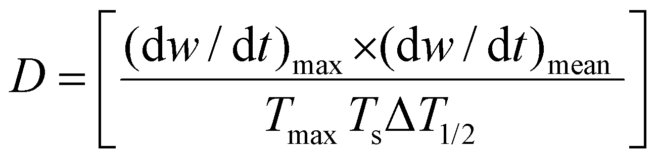 | (1) |
The mesophase can be characterized by a very sharp 002 reflection in the powder X-ray diffractogram. This is an indication of well-stacked graphene sheets, which is a characteristic of condensed aromatic hydrocarbons, like graphite. Similarly, EELS from carbon K-edge demonstrated a σ* peak at ∼293 eV, referring to long-range graphitic ordering.48 Moreover, clear lattice fringes can be observed in high-resolution transmission electron microscopy (HR-TEM) analysis. The degree of graphitization or the ID/IG ratio obtained from Raman spectroscopy has demonstrated there is more ordering for soft carbon than other disordered carbons.
2.3. Mesophase ordering endows unique physicochemical attributes to soft carbon
The unique properties of soft carbon are beneficial for battery applications. First, the formation of a viscous liquid at the softening point assists in the dispersion of the carbonizing precursor on the redox-active core. The liquefaction increases the volume of the coating agent, which spreads and engulfs the surface of the core material, thereby promoting a homogeneous and conformal coating.40 Hence, the coating uniformity is prompted by the occurrence of an intermediate liquid, which is otherwise hard to achieve at solid–solid interfaces. In addition, the glue-like behavior of the viscous liquid can be exploited in binder applications. Second, the carbonized pitch is enriched in 99.3 wt% carbon. The minute amount of heteroatoms renders the surface with resiliency toward electrolyte attacks.48 The achieved interfacial stability improves the cycle life and cycling efficiencies, thereby increasing its chances of being employed as a high-voltage protective coating. Third, the conversion ratio of the carbon-dominant (>90%) precursors to carbon is exceptionally high, i.e., a maximum of 60% at 900 °C, while the heteroatom containing precursors yield <1 wt% hard carbon at the same temperature, which could be attributed to the easy volatilization of O/N heteroatoms. The higher percentage of product yield from soft carbon precursors improves the atom economy, lowers material waste, and reduces gas generation. Fourth, the mesophase ordering manifests a higher Young Modulus and better tensile strength.48 The better mechanical property aids in withstanding volume expansion during the de/lithiation of conversion/alloying materials. Consequently, soft carbon has been successfully utilized as a flexible coating and durable matrix for mitigating the expansion–contraction issues of conversion/alloying electrodes. Fifth, the gas evolution during carbonization ensues a porous morphology to soft carbon. The porosity can be designed to a hierarchical one via synthetic modifications. The obtained macropores (>50 nm) can be channels for electrolyte passing, while the mesopores (2–50 nm) may offer channels for ion diffusion, and micropores (<2 nm) are the active ion-storage sites.49 Therefore, soft carbon as a coating material eases electrolyte infiltration and allows storing active ions when used as a redox-active material. Sixth, the ordered arrangement ensures a fast and non-tortuous pathway of electron mobility. The resulting higher electronic conductivity can be exercised in the carbon-binder domain, replacing C-65 carbon black.50 The relatively lower surface area of soft carbon is also beneficial for this purpose if the carbon-binder domain contributes to the parasitic side reactions at the interface.3. Soft carbon as a matrix for alloying/conversion electrodes
As discussed in the literature, the ideal carbon framework for conversion/alloying electrodes must possess three essential characteristics: interfacial cohesion, spatial connection, and structural stability.51Fig. 2a is a pictorial presentation of the requisites. The term ‘interfacial cohesion’ refers to bonding (electrostatic or chemical) between the active material and carbon framework. Good interfacial cohesion hinders particle pulverization and delamination during high-volume changes. The ‘spatial connection’ indicates the connectivity of the entire carbon framework, which provides electrochemically active sites to incorporate alloying particles and offers enough space to accommodate the expanded volume. It also maintains electrical continuity throughout the electrode. The third characteristic, i.e., ‘structural stability’, is the capability of the carbon framework to sustain repeated volume expansion/contraction during cycling without breaking.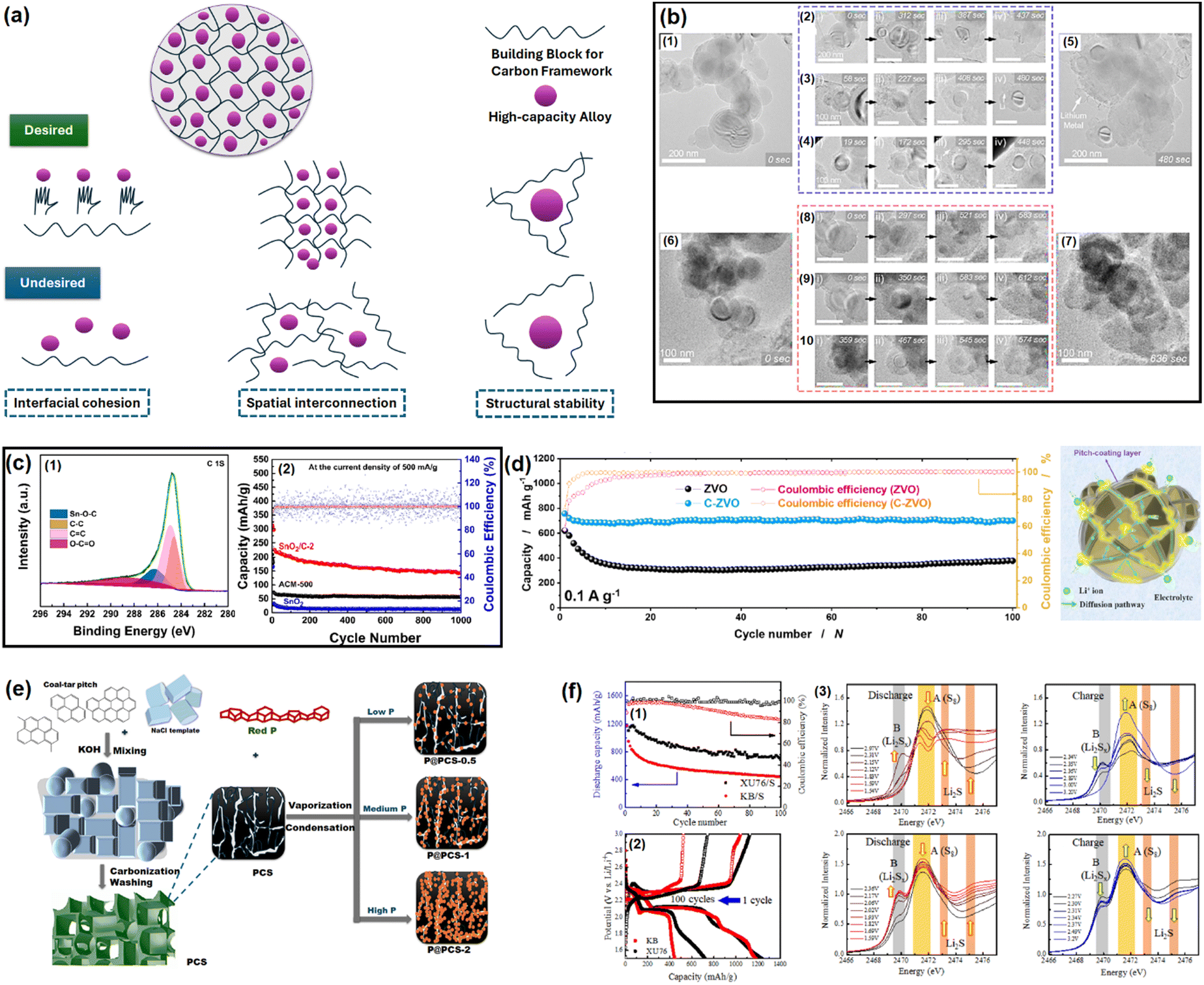 | ||
| Fig. 2 (a) Properties of an ideal carbon framework for conversion/alloying electrodes. Inspired from ref. 50. (b) In situ electrochemical TEM observation of a Si/C composite at different time intervals. Reused from ref. 57 with permission. Copyright 2019 American Chemical Society. (c) C 1s XPS spectra of a SnO2/C composite to distinguish Sn–O–C bond and galvanostatic cycling at 500 mA g−1 for up to 1000 cycles. Reused from ref. 67 with permission. Copyright 2021 American Chemical Society. (d) Cycling performance test of Zn3V2O8 and Zn3V2O8/C at 100 mA g−1, and an animated representation on the usefulness of pitch-derived carbon coating. Reused from ref. 68 with permission. Copyright 2020 American Chemical Society. (e) Vaporization–Condensation method of confining ultrafine nanosized red P in a 3D pitch-derived porous carbon skeleton. Inspired from ref. 50. (f) Capacity retention plots of soft carbon/sulfur and Ketjen black/sulfur composites (1), the corresponding voltage profiles (2), and operando S K-edge X-ray absorption spectra for detecting polysulfide dissolution (3). Reused from ref. 73 with permission. Copyright 2022 American Chemical Society. | ||
3.1. Si-based anodes
Si-based anodes, i.e., Si, silicon oxide (SiOx), silicon oxycarbide (SiOxCy), and silicon nitride (SiNx), are among the most propitious anodes for high energy density batteries.52 Compared to graphite, elemental Si as an anode offers various benefits in terms of material density (2.2 g cm−3 for graphite vs. 2.3 g cm−3 for Si), theoretical gravimetric capacity (372 mA h g−1 for graphite vs. 4200 mA h g−1 for Si), and theoretical volumetric capacity (840 mA h cm−3 for graphite vs. 9660 mA h cm−3 for Si).53 Despite its advantages, the electrochemical cycling of Si faces enormous challenges due to the colossal volume change (>300% for Si vs. <10% for graphite) upon full de/lithiation leading to material pulverization and detachment from the current collector, poor electronic conductivity (∼10−5 S cm−1 for Si vs. 104 S cm−1 for graphite), sluggish Li+ mobility inside the bulk (10−14–10−13 cm2 s−1 for Si vs. 10−9–10−7 cm2 s−1 for graphite), etc.54 These intrinsic drawbacks can be mitigated by coupling Si with carbon. The development of Si/C composites was initiated by hybridizing Si with graphite. After two decades of research and development, novel strategies have been optimized to integrate Si with carbon, like nanohybrids, matrix embedment, yolk–shell, core–shell, carbon impregnation in Si, etc.55 It has also been found that the properties of carbon have a significant impact on cyclability.56In a very recent article by Sun et al., SiOx was projected to be more compatible with soft carbon than graphite.57 A coal tar pitch-derived soft carbon at 1600 °C (d002 = 0.333 nm and ID/IG = 0.80) was reported to perform far better than graphite (d002 = 0.345 nm and ID/IG = 0.15) when composited with SiOx at a 1![[thin space (1/6-em)]](https://www.rsc.org/images/entities/char_2009.gif) :1 ratio. The reason was attributed to the bidirectional diffusion of Li+ across the SiOx/carbon interface. The lithiation of SiOx happens in two stages: Si → LixSiy (0.45–0.17 V) and LixSiy → Li15Si4 (0.17–0.01 V), whereas graphite demonstrates three significant stages, i.e., LiC24 → LiC18 at 0.20 V, LiC18 → LiC12 at 0.10 V, and LiC12 → LiC6 at 0.07 V. The difference in the lithiation potential drives the preferential lithiation of SiOx before graphite in SiOx/graphite composite during the charge process, which results in the greater accumulation of Li on SiOx particles than adjacent graphite particles at the early stages of lithiation. As the lithiation (charging) proceeds close to the potential for graphite lithiation, the already established lithium concentration gradient ushers the direction of Li+ flow to SiOx → graphite. This triggers an anomalous reverse flow of lithium from the SiOx core → surface, while the natural lithiation process of SiOx surface → core is also underway as the system is charging (lithiating). This reverse direction of Li+ inside SiOx leads to a contraction of the SiOx outer layer, thereby promoting an inward compressive stress. Subsequently, the natural direction of lithium flow gets impeded, yielding a significant internal polarization, and the lithiation capacity of SiOx remains underutilized. Therefore, the SiOx/graphite composite succumbs prematurely to the bidirectional lithium diffusion. In contrast, the higher or partially overlapping lithiation potential of soft carbon than SiOx and the sloping voltage profile of soft carbon can mitigate the issue. Moreover, polycrystalline soft carbon is made of directionally oriented nanocrystals, which offer numerous low-energy migration paths, which reduces the diffusional resistance of Li+. Hence, the soft carbon exhibits better compatibility with SiOx. By the same line of logic, hard carbon having a sloping lithiation profile and higher lithiation potential than Si-based anodes should be a good coating alternative. Nava et al. in 2019 found that a higher degree of graphitization of the coating layer favored the transport of lithium within the system when a carbon shell was vapor deposited (7–8 nm) on a silicon core.58 The in situ electrochemical TEM study revealed that the shell with a lesser graphitic degree (processed at 400–900 °C) prevented the transport of Li+ to the Si core and mechanically constrained the expansion of the underlying Si nanoparticles, thereby generating higher charge-transfer resistances. The in situ electrochemical TEM images of the Si/C composite at different time intervals during dis/charge are presented in Fig. 2b. On the other hand, the shell with a relatively higher graphitic degree (processed at 1000–1200 °C) eased the diffusion of Li+ toward the Si core, which could accommodate the volume change of the Si core without any delamination. Therefore, the microstructure of the carbon encapsulation layer could not only buffer the volume expansion but also alter the Li+-diffusion properties significantly in the Si–core–carbon–shell structure.59 The microstructure can be precisely controlled by tuning the carbonization temperature. In a report by Du et al. in 2022, the carbonization of coal-based mesophase pitch at 1400 °C (d002 = 0.3455 nm, ID/IG = 1.067, BET surface area = 8.45 m2 g−1, and average pore volume = 0.038 cm3 g−1) improved the capacity retention of a Si (15 wt%)/C composite anode by ∼54% over 200 cycles at a 200 mA g−1 current density compared to than at 800 °C (d002 = 0.3551 nm, ID/IG = 1.156, BET surface area = 31.06 m2 g−1, and average pore volume = 0.015 cm3 g−1).60 Again, the reason was ascribed to the better graphitic degree, crystallinity, structural stability, and pore distribution in the high-temperature carbonized sample, which offered better alloying with Si. The weight percentage of carbon in the composite also influences the electrochemical performances. Kim et al. prepared a SiOx/soft carbon composite in various weight percentage ratios of SiOx and soft carbon ranging from 9:1 to 5:5, where the soft carbon was derived by carbonizing pyrolysis fuel oil at 900 °C (ID/IG = 0.98 and % Csp2/sp3 = 2.26, coating thickness = 0–600 nm).61 The 8:2 composite was found to be the optimized one as it retained 60% of its initial capacity at 300 cycles, while the pristine SiOx was exhausted at around 100 cycles.
:1 ratio. The reason was attributed to the bidirectional diffusion of Li+ across the SiOx/carbon interface. The lithiation of SiOx happens in two stages: Si → LixSiy (0.45–0.17 V) and LixSiy → Li15Si4 (0.17–0.01 V), whereas graphite demonstrates three significant stages, i.e., LiC24 → LiC18 at 0.20 V, LiC18 → LiC12 at 0.10 V, and LiC12 → LiC6 at 0.07 V. The difference in the lithiation potential drives the preferential lithiation of SiOx before graphite in SiOx/graphite composite during the charge process, which results in the greater accumulation of Li on SiOx particles than adjacent graphite particles at the early stages of lithiation. As the lithiation (charging) proceeds close to the potential for graphite lithiation, the already established lithium concentration gradient ushers the direction of Li+ flow to SiOx → graphite. This triggers an anomalous reverse flow of lithium from the SiOx core → surface, while the natural lithiation process of SiOx surface → core is also underway as the system is charging (lithiating). This reverse direction of Li+ inside SiOx leads to a contraction of the SiOx outer layer, thereby promoting an inward compressive stress. Subsequently, the natural direction of lithium flow gets impeded, yielding a significant internal polarization, and the lithiation capacity of SiOx remains underutilized. Therefore, the SiOx/graphite composite succumbs prematurely to the bidirectional lithium diffusion. In contrast, the higher or partially overlapping lithiation potential of soft carbon than SiOx and the sloping voltage profile of soft carbon can mitigate the issue. Moreover, polycrystalline soft carbon is made of directionally oriented nanocrystals, which offer numerous low-energy migration paths, which reduces the diffusional resistance of Li+. Hence, the soft carbon exhibits better compatibility with SiOx. By the same line of logic, hard carbon having a sloping lithiation profile and higher lithiation potential than Si-based anodes should be a good coating alternative. Nava et al. in 2019 found that a higher degree of graphitization of the coating layer favored the transport of lithium within the system when a carbon shell was vapor deposited (7–8 nm) on a silicon core.58 The in situ electrochemical TEM study revealed that the shell with a lesser graphitic degree (processed at 400–900 °C) prevented the transport of Li+ to the Si core and mechanically constrained the expansion of the underlying Si nanoparticles, thereby generating higher charge-transfer resistances. The in situ electrochemical TEM images of the Si/C composite at different time intervals during dis/charge are presented in Fig. 2b. On the other hand, the shell with a relatively higher graphitic degree (processed at 1000–1200 °C) eased the diffusion of Li+ toward the Si core, which could accommodate the volume change of the Si core without any delamination. Therefore, the microstructure of the carbon encapsulation layer could not only buffer the volume expansion but also alter the Li+-diffusion properties significantly in the Si–core–carbon–shell structure.59 The microstructure can be precisely controlled by tuning the carbonization temperature. In a report by Du et al. in 2022, the carbonization of coal-based mesophase pitch at 1400 °C (d002 = 0.3455 nm, ID/IG = 1.067, BET surface area = 8.45 m2 g−1, and average pore volume = 0.038 cm3 g−1) improved the capacity retention of a Si (15 wt%)/C composite anode by ∼54% over 200 cycles at a 200 mA g−1 current density compared to than at 800 °C (d002 = 0.3551 nm, ID/IG = 1.156, BET surface area = 31.06 m2 g−1, and average pore volume = 0.015 cm3 g−1).60 Again, the reason was ascribed to the better graphitic degree, crystallinity, structural stability, and pore distribution in the high-temperature carbonized sample, which offered better alloying with Si. The weight percentage of carbon in the composite also influences the electrochemical performances. Kim et al. prepared a SiOx/soft carbon composite in various weight percentage ratios of SiOx and soft carbon ranging from 9:1 to 5:5, where the soft carbon was derived by carbonizing pyrolysis fuel oil at 900 °C (ID/IG = 0.98 and % Csp2/sp3 = 2.26, coating thickness = 0–600 nm).61 The 8:2 composite was found to be the optimized one as it retained 60% of its initial capacity at 300 cycles, while the pristine SiOx was exhausted at around 100 cycles.
Transforming the benefits of soft carbon into an industrial-grade Si/C composite is a tedious task.62–65 Chae et al. fabricated a micrometer-sized Si/C composite by impregnating petroleum pitch into nanoporous silica and calcining at 700 °C for 1 h in flowing Ar gas.66 The important characteristics of the process were as follows: (a) the use of toluene as solvent protected the Si surface from autooxidation, as the high solubility of pitch in NMP and THF catalyzes oxidation; (b) the negative surface charge of pitch in toluene enabled a homogeneous distribution on the positive surface charge containing Si via electrostatic interaction. Moreover, the application of a vacuum during the impregnation process assisted the permeation of pitch into the nanochannels of Si via capillary action; (c) the optimized process preserved the nanostructure (<4 nm) of Si by restricting its uncontrolled crystal growth and the shrinking of nanopores during the carbonization process; and (d) the specific surface area of the nanosilicon decreased from 972 to 8.8 m2 g−1 with a concomitant increase in the tap density from 0.48 to 0.93 g cm−3 after soft carbon processing. Both these latter parameters are vital for industrial applications and can only be achieved by the strategic utilization of soft carbon. Aided by the robust network of 45 wt% soft carbon, the silicon anode coupled with LiNi0.5Mn0.3Co0.2O2 (NMC532) retained 80% capacity at 450 cycles in an industrial-scale pouch-cell set-up, whereas the conventional chemical vapor-deposited carbon (12 wt%)-silicon composite suffered from drastic capacity fading. This unique process paves the way for Si/soft carbon composite toward industrial adoption.
3.2. Other anodes
SnOx-based materials exhibit application prospects in SIB anodes.67 However, their practical applications are restrained by poor electrical conductivity and huge volume expansion. To mitigate these issues, nano-SnO2 (∼5 nm) was dispersed within the pitch-derived carbon matrix via a one-pot hydrothermal technique.68 With the aid of Sn–O–C bonds, as observed in the XPS analysis and as shown here in Fig. 2c, the SnO2/C composite delivered a residual capacity of 144 mA h g−1 after 1000 cycles at 500 mA g−1, while the bare SnO2 faded rapidly (only ∼50 mA h g−1 under similar conditions) owing to the severe volume change (Fig. 2c). The improvement was ascribed to the robust anchoring effect of the soft carbon matrix, which could resist material pulverization. A similar performance achievement was also reported using pitch-infiltrated SnO2–CoO yolk–shell microspheres as an LIB anode, which demonstrated a 46% enhancement in capacity retention compared to an uncoated sample over 100 cycles at 1 A g−1 current density.Another interesting report where pitch-derived soft carbon was utilized as an efficient matrix involved a Zn3V2O8 LIB anode69 (Fig. 2d). It is a conversion material that reacts through a 7-electron-transfer process. Nonetheless, its electrical and ion conductivity limitations, and volume expansion can be simultaneously relieved by the use of pitch-derived soft carbon. A combination of in situ XRD, ex situ X-ray absorption spectroscopy, and TOF-SIMS revealed the de/lithiation mechanism of Zn3V2O8/C. Assisted by the carbon wrapping, the material exhibited an excellent capacity retention of 735 mA h g−1 representing 96% of the initial capacity after 100 cycles at 100 mA g−1 current density, whereas nanoplatelets of the bare sample retained only 64% at the 40th cycle under similar test conditions (Fig. 2d). Meanwhile, red phosphorous (P) has emerged as an efficient anode for Li/Na/K-ion batteries.70 Liu et al. confined ultrafine nanosized red P in a 3D pitch-derived porous carbon skeleton consisting of interconnected nanosheets via a vaporization–condensation mechanism, as shown in Fig. 2e.71 Beyond the common requisites of a high electrical conductivity and the suppression of volume expansion, the micro/mesoporous (1–3 nm) and oxygen-rich carbon architecture enabled a high P loading with uniform dispersion. The material excelled as an LIB and KIB anode, showing 557 mA h g−1 reversible capacity at 2 A g−1 for an LIB and 312 mA h g−1 at 500 mA g−1 for 500 cycles for a KIB. Another anode material that is undoubtedly going to be commercialized in the near future is Li metal due to its high theoretical capacity (3861 mA h g−1), low density (0.534 g cm−3), low molar mass (6.941 g mol−1), and low electrochemical potential (−3.04 V vs. standard hydrogen electrode). However, its commercial applications are hindered by interfacial issues leading to uncontrollable dendritic growth that raises safety concerns. Confining the Li metal into a three-dimensional scaffold is a useful approach, which is discussed in detail elsewhere.72–74 Soft carbon may be a potential candidate for this purpose.
3.3. Sulfur cathode
The remarkable electrochemical prospects of the sulfur cathode (theoretical capacity: 1672 mA h g−1, gravimetric energy density: 2600 W h kg−1, volumetric energy density: 2200 W h L−1) are bottlenecked by its poor conductivity, polysulfide species formation and dissolution, sluggish de/lithiation kinetics, sulfur leaching due to volume expansion, and rapid capacity fading.75 An effective solution to mitigate these issues simultaneously is to confine sulfur within a carbon matrix. An ideal carbon structure must contain optimum sized pores, uniform pore distribution, and interconnectivity between the mesopores and micropores. The micropores provide a high surface area and close contact, while mesopores supply ion pathways and act as sulfur and electrolyte reservoirs.76–79 An overabundance of micropores leads to low sulfur loading and poor ionic transport, whereas too many mesopores reduces the electrochemically active contact areas and sulfur utilization.Ko et al. fabricated a porous carbon using petroleum pitch precursors via a template carbonization that balanced all the desired properties.80 The synthesized soft carbon (named as XU76) possessed a particle dimension, surface area, mesopore size, and pore volume of 20 nm, 1005 m2 g−1, 4.0 nm, and 0.6 m2 g−1, respectively, enabling 66% sulfur loading, while for the vapor-phase aggregated commercial Ketjen Black (KB) carbon, the values were 50 nm, 1205 m2 g−1, 3.9 nm, and 1.7 m2 g−1, respectively, realizing only 55% sulfur loading. The mesopore-dominant (as revealed by small-angle neutron scattering) KB carbon delivered only 400 mA h g−1 after 100 cycles at a C/10 rate, whereas XU76 having an interconnected pore geometry demonstrated a value of ∼700 mA h g−1 after 100 cycles under similar cycling conditions (Fig. 2f(1)). The voltage profiles are shown in Fig. 2f(2). The mechanism behind these better electrochemical performances was characterized by operando Raman spectroscopy. This revealed that the long-chain and short-chain polysulfides disappear and reappear at the fully discharged (1.5 V vs. Li+/Li) and fully charged (3.2 V vs. Li+/Li) states, hinting at reversible sulfur redox in the case of the soft carbon (XU76)-integrated sulfur. In contrast, the KB-integrated sulfur exhibited the existence of residual polysulfide species under the discharged condition of 1.5 V vs. Li+/Li, suggesting an incomplete sulfur reduction process at the 1C rate. These observations were further confirmed by the operando S K-edge X-ray absorption spectra, which also showed the presence of polysulfide species at the discharged condition for the KB/sulfur cathodes (Fig. 2f(3)). The authors concluded that the mesopores in XU76 confined the polysulfides and restrained shuttling during cycling and that interconnected pores were accessible to the polysulfides and electrolytes, while the small micropores of KB carbon were not accessible for the active ionic species, thus leading to the deterioration in cycling performance.
In another report, Park et al. derived a yolk–shell-structured soft carbon microsphere from mesophase pitch via Fe2O3 template/HCl etching.81 The melt diffusion of sulfur allowed achieving a 70 wt% loading. The system achieved 686 mA h g−1 reversible capacity at a C/2 rate, while the conventionally loaded sulfur in porous carbon achieved only 236 mA h g−1. The better cycling and excellent rate performances were attributed to the synergistic effects of the high electrical conductivity and empty shell layers of the soft carbon matrix.
In summary, soft carbon has been confirmed to be an efficient matrix for sulfur. The extent of the electrochemical improvement for Li–S batteries depends on the best trade-off between the porosity and structure of the soft carbon.
4. Soft carbon as a redox-active electrode material
Graphite was the first material ever used for ion storage.82 It has an amphoteric redox property, meaning it can accommodate cations, anions, and neutral species in the bulk via intercalation chemistry. The resulting ‘graphite-intercalation compounds’ (GICs) are known as donor-type and acceptor-type for cations and anions, respectively. The exploration of Li-ion intercalation into graphite led to the commercial LIBs that ate available in the market today. However, coke-derived soft carbon was used in the first commercialized LIB by SONY in 1991. Later, graphite captured the market as an anode material because of its unparalleled electrochemical performance. Recently, soft carbon has emerged as a host matrix for K+ and Na+ storage. The entire gamut of carbon materials reported for the purpose of ion storage can be classified into two categories: graphite and disordered hard/soft carbons. The main difference between graphite and hard/soft carbons is the turbostratic disorder, which is defined as the random rotation and translation between adjacent graphene layers originating from low-temperature synthesis. Moreover, hard and soft carbons can be differentiated in terms of their graphitizability. Turbostratic disorders and graphitizability affect the ion-storage mechanism. Hence, the microstructure of soft carbon must be elucidated at first, as the degrees of graphitization and disorderedness heavily rely on the synthetic temperature.4.1. Synthesis of soft carbons: precursors and procedures
Before going into the details of the characterization techniques, let us first see the various ways of deriving soft carbons. Not all carbon-containing materials qualify as a precursor of soft carbon. The precursor should contain sufficient aromatic rings that can be fused to oriented graphene sheets during thermal treatment. If the precursor contains strong crosslinking interactions among its building blocks that cannot be broken even by a temperature beyond 2000 °C, then the resulting product may not lead to the graphitic microdomains of the soft carbon structure. The precursors typically include side products from the petroleum and coal industries, i.e., pitch, pyrolysis fuel oil, and anthracite. The derivation of soft carbon represents a value-added utilization route of these byproducts. Condensed small aromatic moieties, like perylene, pyrene, naphthalene, and phenanthrene, are also used for synthesizing soft carbon. Aromatic-ring-containing polymers can be another potential source, but only vinyl polymers are used commonly as soft carbon precursors.The precursors can be converted into several forms and hybrids of soft carbon via various techniques, as shown in Fig. 3. Thermal treatment can be performed under the flow of an inert gas and below 1500 °C, unless graphite is targeted as the product where >2500 °C is required. According to process (a) in Fig. 3, pitch can be converted into soft carbon via direct calcination. It can be activated via an acid or base to form a pore-rich structure (b). It can also be co-carbonized with biomass precursors to form soft/hard carbon composites (c). Further, heteroatom doping can also be performed easily through multiple processes (d) and (e). The porosity can be precisely controlled using template synthesis (f). Additionally, soft carbon can be produced in fibrous form as per the method shown (g). In another way, pitch precursors can be crosslinked and then carbonized to generate crosslinked carbon (h). Last but not the least, soft carbon precursors can be tuned to mesocarbon microbeads (MCMBs) and graphitized under high-temperature calcination (i).
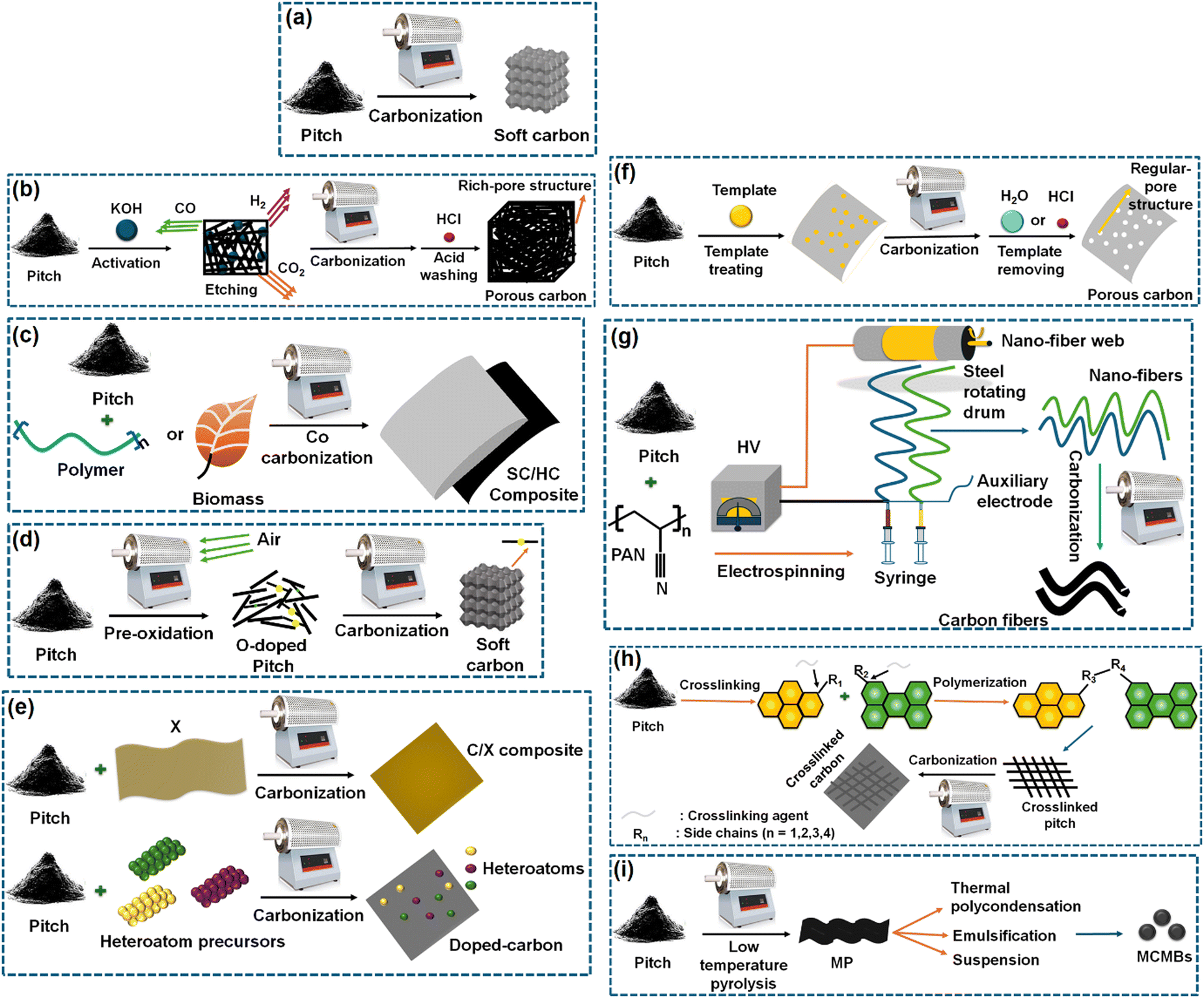 | ||
| Fig. 3 Methods of producing soft carbon structures considering pitch as the standard precursor: (a) soft carbon, (b) porous carbon, (c) soft carbon/hard carbon composite, (d) O-doped soft carbon, (e) heteroatom-doped carbon, (f) pore-controlled soft carbon, (g) soft carbon nanofibers, (h) crosslinked, and (i) mesocarbon microbeads. Inspired from ref. 83. | ||
4.2. Characterization of the structural properties of soft carbon using classical and modern advanced techniques
This section elaborates the ways of tracking the gradual attainment of the graphitization degree with increasing the calcination temperature, see Fig. 4a–f. The physical parameters of soft carbons calcined between 900–2900 °C obtained from various physical characterization techniques are summarized in Table 1. The powder X-ray diffraction (PXRD) pattern of pitch calcined at 2800 °C demonstrated all the reflections of pure graphite, i.e., (002), (100), (101), (102), (004), (103), (110), (112), and (006),84 as shown but not labeled in Fig. 4a. Pitch carbonized at ≤1500 °C does not show general (hkl) reflections and the overlap of the (hk) reflection with (00l), i.e., (10) and (110) at ∼ 42° (2θ) and (11) and (110) at ∼77° (2θ), indicates two-dimensional short-range order, which is not continued in the third direction (Fig. 4b). This is the classic proof of turbostratic non-graphitic carbon as revealed via Ruland–Smarsly fitting of the total scattering profile.85 Now, employing Scherrer's equation, associated parameters can be estimated, such as the average stack height or thickness (Lc), average crystallite size or length (La), and number of stacked graphene layers (N).86 By using the empirical Bragg equation, the average interlayer distance (d) can be determined.87 Moreover, the degree of graphitization (DOG) can be calculated by using equations developed by Feret, Maire, and Aune.88 Maire and Aune's equations in combination are the most suitable for turbostratic carbon with a low graphitization degree.89 All the parameters mentioned above undergo changes with the progression of the carbonization temperature. Up to 1000 °C, the changes are random, and the pitch precursor slowly acquires graphitic domains (increase in DOG) beyond that temperature as reflected in the alterations of the parameters (Table 1). Initially at room temperature, the pitch precursor shows a broad (002) reflection spread across 15°–30°, which can be deconvoluted into two peaks: a γ-band at 19°, which originates from aliphatic side chains, and a π-band at 26°, which indicates the staging of aromatic layers.45 Along with carbonization, the (002) reflection merges into a single peak at 26° and becomes more intense with the higher 2θ angle shift. As a result, d002 decreases with a concomitant increase of La and Lc. Ou et al. determined the same parameters more precisely using a wide-angle X-ray scattering (WAXS) system equipped with advanced fitting via the CarbX program and obtained a similar trend.90 Moreover, they conducted X-ray total scattering experiments and associated pair distribution function (PDF) analysis, which has recently emerged as a powerful tool to study disordered carbon. Their analysis exhibited that the extension of PDF at higher interatom distances (20–100 Å) with increasing temperatures, as shown Fig. 4c, and the greater intensity of PDF at elevated pyrolysis temperatures in the range of 1–6 Å interatom distances, as shown in Fig. 4d, highlight the growth of graphitization, with a parallel reduction in defect concentrations. A closer look at Fig. 4d reveals that the soft carbon microstructures are made up of two domains: the ‘ordered core domains’ at the center extending up to several benzene rings and the ‘disordered surrounding domains’ containing curvy, twisted, and defective graphene sheets. With the temperature increasing, the disordered surrounding domains are transformed into ordered core domains. This transformation is characterized via the atom-displacement parameter (U33) obtained through Rietveld-like refinements, which denotes the displacement of the carbon atom perpendicular to the ab plane. The value of U33 decreases with increasing temperature, indicating the alleviation of turbostratic misalignments of the individual stacks (Table 1). Combining all the data, the authors concluded that the graphitization of the pitch precursors was initiated at 2100 °C.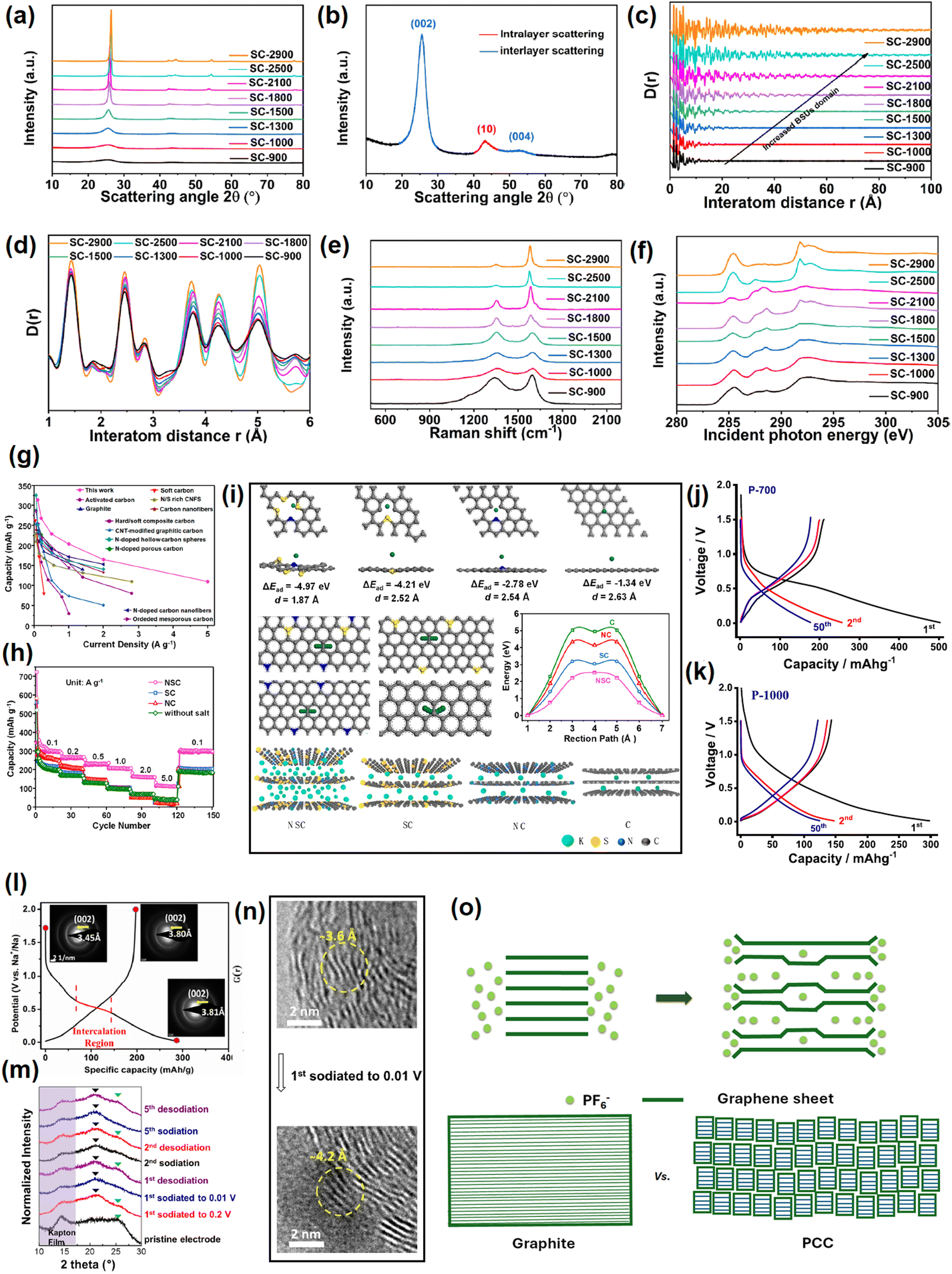 | ||
| Fig. 4 Tracking the evolution of soft carbon's microstructure with increasing the calcination temperature from 900 °C to 2900 °C: (a) power X-ray diffraction pattern, (b) interlayer scattering in powder X-ray diffraction analysis, (c) pair distribution function pattern from 0–100 Å, indicating increased basic structural unit (BSU) domains, (d) pair distribution function pattern from 1–6 Å, indicating alterations in the defect concentrations, (e) Raman spectroscopy, and (f) near-edge X-ray absorption fine structure (NEXAFS) spectroscopy. Fig. 4(a–f) are reused from ref. 83 with permission. Copyright 2021 American Chemical Society. (g) Rate comparison of the referenced report and other reports in the literature on KIB anode. Reused from ref. 97 with permission. Copyright 2020 American Chemical Society. (h) Rate performance comparison between undoped, N-doped, S-doped, and N,S-codoped soft carbons. Taken from ref. 97 with permission. (i) Theoretical simulations on the K-ion-storing affinities of N-doped, S-doped, N,S-codoped soft carbons, and graphite. Reused from ref. 97 with permission. Copyright 2020 American Chemical Society. (j) and (k) Voltage profiles of petroleum pitch-derived soft carbons at 700 °C and 1000 °C as sodium-ion anodes. Reused from ref. 102 with permission. Copyright 2020 Elsevier. (l) 1st cycle voltage profile of soft carbon as an SIB anode showing an irreversible quasi-plateau at 0.5 V vs. Na+/Na. Selected area diffraction (SAED) patterns in the insets show the irreversible expansion of 0.35 Å at first sodiation. Reused from ref. 103 with permission. Copyright 2017 American Chemical Society. (m) and (n) Ex situ XRD and ex situ TEM pattern of de/sodiation. Reused from ref. 104 with permission. Copyright 2015 American Chemical Society. (o) Model of anion storage in graphite and soft carbon. Inspired from ref. 119. | ||
![[double bond, length as m-dash]](https://www.rsc.org/images/entities/char_e001.gif) C) were calculated from wide-angle X-ray scattering (WAXS), Raman spectroscopy, and near-edge X-ray absorption fine structure spectroscopy (NEXAFS). Inspired from ref. 83
C) were calculated from wide-angle X-ray scattering (WAXS), Raman spectroscopy, and near-edge X-ray absorption fine structure spectroscopy (NEXAFS). Inspired from ref. 83
| Calcination temp. (°C) of soft carbons | d 002 (Å) | L a (Å) | L c (Å) | U 33 (Å2) | I G/ID | σ* (CC) |
|---|---|---|---|---|---|---|
| 900 | 3.592 | 15.216 | 27.045 | 0.200 | 0.244 | 0.155 |
| 1000 | 3.574 | 25.270 | 38.067 | 0.197 | 0.266 | 0.164 |
| 1300 | 3.502 | 32.025 | 44.517 | 0.195 | 0.361 | 0.173 |
| 1500 | 3.483 | 47.835 | 72.116 | 0.205 | 0.511 | 0.200 |
| 1800 | 3.459 | 89.727 | 122.028 | 0.227 | 1.303 | 0.197 |
| 2100 | 3.438 | 140.492 | 240.000 | 0.160 | 2.104 | 0.192 |
| 2500 | 3.395 | — | — | 0.044 | 5.404 | 0.259 |
| 2900 | 3.360 | — | — | 0.034 | 5.417 | 0.253 |
Another reliable method to measure the graphitic order is Raman spectroscopy.91 The characteristic D-band (disordered) and G-band (graphitic) exist between 1200–1650 cm−1. The entire zone can be deconvoluted into a maximum of 5 peaks (4 D-bands and 1 G-band) via Gaussian–Lorentzian numerical fitting (please refer to the figure 3 of the cited article).84 The D1 band at 1220 cm−1 could be attributed to the carbon atoms that bind sp2–sp3 bonds. The D2 band that appeared at 1350 cm−1 arose from the A1g vibration mode of sp2-hybridized carbons located at the edges and defects of the graphene sheets. The D3 band around 1540 cm−1 was related to the short-range lattice vibration of sp3-hybridized amorphous carbons. The G-band around 1590 cm−1 was attributed to the E2g stretching vibration mode of sp2-hybridized graphitic carbons. The D4 band located around 1620 cm−1 was assigned to the lattice vibrations of surface carbon atoms. The intensity or area ratio of G/D3 (IG/D3 or AG/D3) is an indicator of the graphitization degree, which increases with increasing temperature. This ratio is also useful to quantify the average crystallite size or length, also known as La-Raman. On the other hand, the ratio of D2/G corresponds to sp2 active sites at edges and defects, which decreases at elevated temperatures. In addition, the appearance of a 2D band at ∼2700 cm−1 referred to the augmented graphene sheet stacking.92 The changes in the Raman spectra with calcination temperature are provided in Fig. 4e and the values are provided in (Table 1). Further, the evolution of the graphitic degree with the progression of carbonization can be tracked via electron paramagnetic resonance (EPR) spectroscopy.93 The signals in EPR originate from the unpaired electrons. The technique is sensitive toward defects in the non-zero spin state, and therefore, cannot distinguish the type of defects. However, the line shape delineates useful information about the generation, rearrangement, and combination of organic free radicals during the course of pitch carbonization. Up to 800 °C, a symmetrical line shape is observed, which represents the maximum concentration of unpaired electrons.84 The high spin density at low annealing temperatures is attributed to the splitting of O and H in the radical form, thereby leading to an isotropic EPR signal. The signal disappears in the range of 900–1500 °C, which may be due to the probable merging of radical-containing structural units.84 The signal can be detected back at ≥1800 °C in the form of an asymmetric line shape, also known as a ‘Dysonian-shaped signal’,94 which indicates a low spin concentration and occurs because the increase in stacking order at this temperature surpasses the electron diffusion length, as visible in highly conducting samples like graphite. Thus, EPR spectroscopy can differentiate several stages of graphitization qualitatively. However, the limitation lies in distinguishing non-graphitic from graphitic carbons (differ in stacking order), as the EPR signals arise from the free electrons within the nanosized graphene sheets, which are not sensitive to the stacking order.
Surface area and the pore structure can be evaluated from BET measurements. At 600 °C, carbonized pitch demonstrated type-I/IV N2 isotherms, which indicated the coexistence of micropores and mesopores.84 The surface area was high (269 m2 g−1) due to the cracking of aliphatic side chains and gas evolution. The surface area decreased to ∼42 m2 g−1 around 800 °C because of condensation and aromatization reactions. From 800 °C onwards, the materials showed a type-IV isotherm, indicating the presence of mesopores. Unexpectedly, the surface area increased again at 1000 °C due to the evolution of residual H2 gas.84 Beyond 1000 °C, the gradual aromatization and disappearance of defects decreased the surface area to 3 m2 g−1 at 1200 °C and ≤1 m2 g−1 at 2800 °C. Further, information about the distribution and alignment of pores can be tracked by soft-angle X-ray scattering (SAXS),95 which also possesses the sensitivity to differentiate hard and soft carbons. Pitch-derived soft carbon at 1300 °C demonstrated a straight-line scattering curve in the Q (scattering vector) range of 0.08–1 Å−1, illustrating the lack of inner and outer pores.96 In contrast, hard carbon derived from an alkali lignin precursor at 1300 °C showed a hump in the same Q range, indicating a porous structure. Further, using the semi-empirical Teubner–Stray model, the average pore size and pore–pore distance in hard carbon were calculated to be 5.18 and 1.79 nm, respectively. The abundance of defects and heteroatoms causes a bending of the graphenic layer, resulting in a disordered arrangement.90 Hence, the structural density of hard carbon (2.01 g cm−3) was lower than that of soft carbon (2.25 g cm−3).
Another important characteristic to be determined is the fraction of sp2 and sp3 carbons, for which X-ray spectroscopic techniques have evolved as powerful tools.97 First, the deconvolution of the X-ray photoelectron spectra (XPS) generates two separate peaks for sp2-C and sp3-C at 284.6–284.8 and 285.2–285.5 eV, respectively. The area ratio of sp3 to sp2 was reported to decrease from 2.32 at 600 °C to close to 0 at 2800 °C.84 Second, near-edge X-ray absorption fine structure spectroscopy (NEXAFS) can also quantify the change in sp2 ratio with pyrolysis temperature.98 Soft carbon exhibited typical peaks at 285.4, 291.7, and 292.8 eV originating from (1s → π*) and (1s → σ*) transitions of aromatic groups, as shown in Fig. 4f. The peaks within the 287–290 eV zone arising from stacking faults disappeared at 2500 °C, indicating greater orderedness.90 The sp2 ratio could be calculated from the peak–area ratio between σ* (CC) and all σ*, which increased from 0.155466 at 900 °C to 0.253071 at 2900 °C (Table 1). Third, X-ray excited C KVV Auger emission spectroscopy is also very useful for evaluating the ratio of sp3 to sp2.99 This technique is very popular for studying the sp3/sp2 ratios of diamond films, but has not been well explored for soft carbons. With the increase in sp2 carbon and stacking order, the electronic conductivity will also increase.
Electron microscopy can assist in the direct visualization of graphitic domains and defects. Scanning electron microscopy (SEM) images have shown that the number of stacked nanosheets increases with pyrolysis temperature. In addition, the number of edge sites decreases with the gradual increase in average particle size. Microstructures have been observed via transmission electron microscopy (TEM).99 Short-range turbostratic disorders were visible up to 1200 °C, and then when the temperature was raised to more than 1500 °C, long-range ordered graphitic domains started appearing.84 Beyond 2500 °C, a great extent of long-range order was observed.
4.3. Soft carbon as an anode for Li+, Na+, and K+ (cation) storage
The ion-storage mechanisms into carbon can be broadly classified into three categories: intercalation, adsorption, and pore filling.100 The de/intercalation occurs between oriented or partially oriented graphene interlayers. The surface, defects, and grain boundaries are sites for ion de/adsorption. Nanosized pores store ions in the form of metallic cluster or as ions. The slopes and plateaus in the voltage profiles originate from the type of storage that predominantly occurs in the material. The specific capacity of a material also depends on the type of storage.| Soft carbon pyrolysis temperature (°C) | Initial coulombic efficiency (%) | Plateau capacity (%) from the voltage profile | Contribution of the capacitive process from the 0.5 mV S−1 CV curve | Capacity retention at 100 cycles |
|---|---|---|---|---|
| 800 | 73 | 9 | 78 | 61 |
| 1400 | 70 | 29 | 64 | 75 |
| 2000 | 69 | 50 | 37 | 62 |
| 2800 | 73 | 50 | 27 | 83 |
The optimum electrochemical performance depends on the best trade-off between capacitive and diffusion processes. Capacitive-based materials show improved C-rate performances, whereas diffusive-dominated materials tend to yield better cycle life at slow rate. It is difficult to acquire synergistic benefits via conventional synthesis. Sun et al. employed an edge-oxidation-induced densification strategy with pitch, where the formed non-graphitic domains offered low-voltage intercalation sites and the surrounding bulk defective network assisted in fast K+-diffusion.102 A significant performance improvement was achieved in terms of a capacity below 1 V, and good initial coulombic efficiency, C-rate, and cycle life. Moreover, the benefits could also be translated to full cells containing potassium Prussian blue cathode material. In another report, Liu et al. synthesized an ordered-in-disordered soft carbon microstructure with abundant intrinsic defects and enlarged interlayer spacing via an iodination/dehydroiodination-based carbonization of coal tar pitch.103 The iodination resisted the π–π interaction between planar aromatic building blocks by alkyl-bridges and resulted in a crosslinked 3D bulk structure. Benefits were realized in both the C-rate and cycle-life performance.
The reports that are discussed up to this point utilized the most common electrolyte for KIB, which is 0.8 M KPF6 in EC-DEC (ester based). However, ether-based electrolytes can lead to an interesting phenomenon. Jian et al. compared the K+-storage performance of soft carbon anodes using conventional ester and ether-based 1.0 M KPF6 in dimethyl ether (DME) electrolytes.96 The stronger interaction between K+ and DME in [K-DME2]+ required a large desolvation energy of ∼150 kJ mol−1 to intercalate by crossing a 2–3 nm thin inorganic-rich (KF and K2CO3) SEI, thereby proceeding with solvent cointercalation. Conversely, the weaker [K-EC/DEC]+, requiring a maximum ∼70 kJ mol−1 desolvation energy, became desolvated before intercalating through a 18 nm thick organic-rich SEI. The cointercalation based non-desolvation storage in the ether electrolyte lowered the first cycle coulombic inefficiency by 23%, reduced voltage polarization, and induced fast-rate storage, i.e., a better C-rate performance. For example, the anode displayed 156 mA h g−1 at 2 A g−1 current density using the ether electrolyte, which decreases to only 55 mA h g−1 in the ester electrolyte. Despite their several advantages, the special attributes of ether electrolytes were hindered by their poor capacity retention during long-term cycling, i.e., only 43% retention of an 192 mA h g−1 initial capacity after 200 cycles at 100 mA g−1 current, while the conventional ester electrolyte was capable of retaining 90% of the 221 mA h g−1 initial capacity.
Another effective way to increase the capacity is heteroatom doping. Liu et al. claimed to achieve the highest C-rate performance surpassing various literature reports by the aid of N/S dual doping on coal tar pitch-derived carbon, as demonstrated in Fig. 4g and h,104 with the capacitive contribution enhanced. First-principles calculations based on density functional theory showed that heteroatom doping increased the ion-adsorption affinity of the carbon backbone, thereby decreasing K+ mobility to induce faster kinetics (Fig. 4i).
From a mechanistic point of view, soft carbons also exhibit a major slope >0.1 V vs. Na+/Na and a minor plateau region <0.1 V vs. Na+/Na. In the literature, the Na+-storage mechanism is classified in various categories, such as adsorption at surface pores and defects, intercalation within nanographitic domains, pore filling, and chemisorption at surface heteroatoms.107 Ghosh et al. in 2019 concluded that the sloping region originates from the adsorption of Na+ at the defect sites, while the plateau region is a result of pore filling.109 Petroleum pitch calcined at 700 °C displayed 178 mA h g−1 reversible capacity at 30 mA g−1 current density, out of which >90% was obtained from defect adsorption, i.e., capacitive storage (b = 0.81). The voltage profiles are provided in Fig. 4j and k. This observation was further substantiated by the fact that when the calcination temperature was increased to 1000 °C, the reversible capacity decreased to 125 mA h g−1 as the number of defects was reduced (ID/IG of 1.27 at 1000 °C with respect to 1.62 at 700 °C). Jian et al. probed the mechanism using in situ TEM, neutron scattering, and DFT studies.110 The novel insights reported in that study were as follows. Na+ storage in soft carbon proceeds with an irreversible intercalation quasi-plateau at 0.5 V vs. Na+/Na compared to <0.1 V reversible plateau for hard carbon, as depicted in the Fig. 4l. The relatively higher potential plateau was correlated with the more defective local structure of soft carbons than hard carbons. The compressed defects bind Na+ more strongly causing an irreversible expansion of interlayers by ∼0.35 Å, i.e., 3.45 → 3.80 Å, as calculated from the selected area diffraction (SAED) pattern in the inset of Fig. 4l. This irreversible trapping resulted in a 30–35% coulombic inefficiency at the 1st cycle. The reversible capacity of soft carbon originates from only the sloping region, which is in practice nothing but the reversible binding of Na+ with local defects, i.e., vacancies on sp2 graphene layers. On the other hand, the reversible slope capacity of soft carbon is higher than the slope capacity of hard carbon due to the greater numbers of defects. Luo et al. presented soft carbon as a better matrix for sodium-ion storage due to its enormous expandability.111 They used the planar aromatic molecule 3,4,9,10-perylene tetracarboxylic acid-dianhydride (PTCDA, C24H8O6) as a precursor, as its ordered stacking is an ideal arrangement for producing soft carbon. As expected, PTCDA pyrolyzed at 1600 °C exhibited a sharper 002 reflection at 2θ = 25.0° than hard carbon, which corresponded to a d002 value of 3.46 Å. The utilization of PTCDA as a precursor also provides the flexibility to tune the interlayer spacing and graphitic domain size based on the pyrolysis temperature. Using ex situ PXRD in an air-free chamber and ex situ TEM, the authors showed that the sample pyrolyzed at 900 °C underwent interlayer expansion from 3.56 to 4.22 Å (18.5%) during first sodiation, which the authors claimed was the largest ‘breathing’ scale reported for a Na+ matrix without solvent cointercalation up to 2015 (Fig. 4m and n). The structure did not fully revert back to its original state after the 1st desodiation, indicating that the few trapped Na+ ions buttressed the expanded structure, which in turn, facilitated the C-rate performance shown in Fig. 4n.
In summary, the optimally designed soft carbon demonstrated reversible capacities in the range of 200–250 mA h g−1 with an average voltage of 0.5 V vs. Na+/Na. Table 3 summarizes the electrochemical performances of various soft carbon anodes for SIBs. In short, the sodium-ion-storage mechanism in soft carbon is dominated by the reversible capacitive storage at defects, which appears to be the sloping region in the voltage profile. The first cycle irreversibility is caused by the trapping intercalation into the graphenic interlayers, which exhibits a plateau around 0.5 V.
| Metal-ion battery | Precursor/temperature (°C) | Reversible capacity (mA h g−1)@current density (mA g−1) | Capacity retention (%)@current density (mA g−1)/number of cycles |
|---|---|---|---|
| SIB112 | Coal tar pitch + H3PO4 (P-doping)/900 | 251@100 | 79.6@100/200 |
| SIB113 | Anthracite coal/1200 | 222@30 | 89@60/600 |
| SIB114 | PTCDA/900 | 232@20 | 100@800/3500 |
| SIB109 | P-pitch/700 | 178@30 | 78@100/30 |
| SIB115 | Mesophase pitch + HNO3 (N-doping) + H2SO4 (S-doping)/800 | 224@50 | 92.2@1000/1000 |
| SIB116 | Pitch-derived soft carbon coated on lignite-based carbon/1200 | 301.4@50 | 95.3@50/200 |
Zhang, Reimers, and Dahn in their classical report correlated the effect of the turbostratic disorder of soft carbons on the intercalation of lithium.118 It is known that lithium storage in graphite occurs in a staging fashion, where the plateau below 0.1 V vs. Li+/Li arising from the stage 2 → 1 conversion is the largest contributor to the capacity. Now, the turbostratic disorder, defined as the rotation between adjacent graphene sheets existing <2000 °C calcination temperature, fails to accommodate Li+ in the disordered regions, thereby squeezing the stage 2 → 1 plateau. Using mathematical models, the authors showed that turbostratically aligned layers prevent the rotation or translation of AB stacked layers to AA stacking upon lithiation. Lu et al. carried out a systematic study to find out the relationship between the reversible capacity and soft carbon parameters.119 First, the first cycle irreversible capacity was observed to decrease from 62% to 21% when the calcination temperature was increased from 600 °C to 3000 °C. Second, degassing of the precursor prior to carbonization reduced the total capacity loss by 18%. Third, minimizing the surface oxygen concentration and attaining a large crystallite size (Lc) could induce an alleviation of the capacity loss by 25% and 5% maximum, respectively.
4.4. Soft carbon as an cathode for anion storage
The redox property of graphite is amphoteric and it forms graphite-intercalation compounds (GICs) with cations, anions, and neutral molecules.120 It stores Li+ at 0.1–0.2 V vs. Li+/Li. It can also store PF6− at 4.5–4.6 V vs. Li+/Li. Thus, if the transition metal-based cathode is substituted by a graphite-based material and coupled with a graphite-based anode, the Li+ and PF6− originating from dissociation of the LiPF6 salt intercalate simultaneously into the anode and cathode, respectively, at charge and come back to the electrolyte during discharge.121 This ion movement is different from the conventional rocking-chair-type mechanism of LIBs, where only Li+ exerts a to and fro motion between the cathode and anode. Therefore, we have coined the term ‘scissor cutting mechanism’ and the system is known as ‘dual-graphite’/‘dual-ion’/‘dual-carbon’ batteries.122,123 Through the scissor cutting mechanism, the system could deliver ∼4.5 V output voltage without using any scarce, costly, and toxic transition metals, thereby emerging as a sustainable analog of next-generation LIBs.124Graphite stores ions via a ‘staging mechanism’, where graphite undergoes the formation of a higher number of stages to lower number of stages with the progression of ion intercalation. This is followed for both cases of cations and anions. The details on the same can be found elsewhere.125 Now, the staging mechanism is activated via a ‘surface effect’, in which anions form higher-stage GICs at the surface sites first, which then diffuse inside the graphite bulk and form higher-stage GICs initially, thereby gradually evolving lower-stage GICs. Therefore, the surface sites play an important role as they form lower-stage GICs ahead of the bulk sites. Meanwhile, petroleum coke-derived soft carbon at 1500 °C leads to small graphitic domains, where each domain has the capability to form GICs. The PF6−-storage profiles of graphite and soft carbon markedly differ. Graphite shows a relatively lower capacity accompanied by gradual stage evolution, whereas soft carbon exhibits a more sloping profile but higher capacity.126 Besides, the cyclic voltammogram of graphite has two independent and distinct sets of peaks, i.e., at 4.5 and 5 V, while they are located in a narrow voltage zone of 4.8–5.0 V for soft carbon, indicating interlinks between the redox reaction, which are absent in graphite. Based on in situ Raman and XRD, Shen et al. proposed a new model of ion storage applicable for soft carbon (Fig. 4o).126 Soft carbon also follows the surface to bulk diffusion phenomenon, where stage evolution at the bulk lags the surface. But it skips the gradual evolution from higher to lower numbered stages. At first, the anions form stage-I GICs at the near-surface region followed by their diffusion into the bulk and the subsequent formation of direct stage-II at the bulk, which further form stage-I. Hence, the sluggish higher to lower stage transition (4 or higher → 1) of graphite is avoided by soft carbon (2 → 1). That is how soft carbon demonstrated ∼100 mA h g−1 capacity at a 2C rate. The peculiar behavior of anion storage also improves the C-rate performance. At 5 A g−1, soft carbon and graphite deliver ∼60–70 and 30–35 mA h g−1 capacity, respectively.
5. Soft carbon as a coating agent for redox-active electrode materials
5.1. Graphite anodes
Commercial graphite anodes are equipped with a soft carbon coating that benefits their electrochemical performances, which is added during the manufacturing stage in order to smoothen the rough surface of graphite. Basic investigations of the effect of the coating were initiated around the 2000s. Yoon et al. derived a coating on artificial graphite using 10 wt% coal tar pitch precursors,127 which improved the 1st cycle coulombic efficiency from 53% to 70%. Inefficiencies >0.25 V vs. Li+/Li at the 1st cycle originated from the electrolyte decomposition at the graphene edge sites, whereas inefficiencies <0.25 V vs. Li+/Li were ascribed to irreversible Li+ trapping into the interlayers. The coating mitigated both, thereby bringing about a 17% enhancement. The same was also reflected in the reduction of irreversible peaks at 0.9 and 0.6 V vs. Li+/Li peaks at differential capacity profiles. Moreover, the coating alleviated H2 and C2H4 gas evolution, which were generated from the decomposition of carbonate solvents and side reactions involving acidic impurities, respectively. Meanwhile, the efficiency of the coating depends on the molecular properties of the pitch precursor, as shown in the study by Jo et al.128 The physical properties and electrochemical performances of three different petroleum pitch precursors having different softening points were found to vary. The pitch precursor with higher softening point possessed a greater fraction of THF insolubles, larger constituent molecules, and better carbon conversion ratio. As a result, it enabled improved coulombic efficiency at the 1st cycle, C-rate performance, and capacity retention. Han et al. obtained the same results using coal tar pitch precursors.129 The 1st cycle capacity at the C/10 rate, corresponding to the coulombic efficiency, and capacity at the 5C rate of the coated sample were enhanced from 343 → 361 mA h g−1, 88.2% → 90%, and 120 → 235 mA h g−1, respectively, with respect to the pristine graphite. These improvements were correlated with the molecular structure of the pitch. The hexane-soluble portion of coal tar pitch was volatile and composed of low molecular weight small compounds that left a multitude of surface defects when carbonized at 800 °C, hindering Li+ permeability. The hexane-insoluble–toluene-soluble fraction possessed a high softening point and the better fluidity during carbonization, ensuring a uniform coating. From the combination of these results, it was concluded that pitch precursors having higher softening points are more suitable candidates for achieving a homogeneously distributed carbon coating.In all three discussed literatures, the parameter that showed the most significant improvement upon coating was the C-rate performance, which thus demands a separate discussion. First, Kim et al. revealed the mechanism of the C-rate improvement, as shown in Fig. 5a.130 The randomly arranged graphene sheets with large interlayer spacing in soft carbon inherently enhanced the high-rate performance. Further, this study shed light on an underdiscussed aspect, namely the ‘spherical particle effect’. Here, uncoated graphite particles are oriented in the perpendicular direction of the current collector under the force created during electrode rolling process. The direction is also perpendicular to the direction of the incoming Li+ flux, which hinders ionic mobility and hampers fast migration. However, uniformly pitch-coated graphite particles relieve orientational blockage by imparting a more spherical particle shape, which facilitates Li+ diffusion. The wt% was optimized to be 5% in that study. On the hind side, an excessive wt. percentage of coating beyond 10% forced particle agglomeration rather than a thicker coating. The heterogeneous surface increased interfacial impedance and blocked Li+ intercalation. As a consequence, the obtained ratios of the 5C/0.2C discharge capacities were 9.07%, 80.58%, 68.15%, 67.35%, and 48.26% in the cases of the pristine, 5%, 10%, 15%, and 20% coated samples, respectively, Fig. 5a. Second, Zheng et al. investigated the relation between the SEI and a fast charging of graphite.131 The study revealed that the soft carbon coating containing more CO functional groups induced an evenly distributed inorganic film rich in LiF derived from LiPF6 salt, while the scenario of the uncoated electrode was detected by in-depth XPS profiling, which showed an inner inorganic layer covered by outer organic layer. The hybrid layer on the uncoated electrode presented a charge-transfer barrier of 49.22 kJ mol−1, which was 1.86 kJ mol−1 higher than the coated electrode, as exhibited in Fig. 5b. Moreover, the outer organic layer dissolved in organic solvent during high current and the sustained growth of Li dendrites perforated the separator, thereby leading to rapid capacity decay under fast charging.
 | ||
| Fig. 5 (a) Schematic illustration of Li+ percolation through uncoated, uniformly coated, and excessively pitch-derived carbon-coated graphite electrodes after pressing, and the corresponding C-rate performances. Taken from ref. 123 with permission. Copyright 2022 MDPI. (b) Schematic illustration of Li+ diffusion from the electrolyte to electrode and calculation of the corresponding activation energies of soft-carbon-coated and uncoated graphites. Inspired from ref. 124. (c) Cycling performances of 0, 1.4, 2.9, and 6.7 wt% soft-carbon-coated anatase TiO2 and post-cycling HR-TEM images. Taken from ref. 128 with permission. Copyright 2014 American Chemical Society. (d) HR-TEM image of soft-carbon-coated Na2Ti3O7, and voltage profiles of different cycles at the C/10 rate, and long-term cycling stability comparison between the coated and uncoated materials at a 10C rate. Taken from ref. 130 with permission. Copyright 2022 American Chemical Society. | ||
5.2. Ti-based anodes
The most popular anode in this category is Li4Ti5O12 (commercial name: LTO), which is a zero-strain material that is more suitable for the development of safe and long-life batteries. However, it suffers from low electrical conductivity at room temperature, which limits the rate performance.132 Carbon coating is one solution to this issue. Jung et al. showed that the electrical conductivity could be increased abruptly to 10−3 S cm−1 by the application of a 2–5 wt% (weight of precursor) pitch-derived soft carbon coating from the 10−9 S cm−1 of the pristine material.133 By virtue of its superior electrical conductivity, the 5 wt%-coated material delivered 81 mA h g−1 capacity at 100C (17.5 A g−1), whereas the pristine material failed to deliver more than 30 mA h g−1. The next material in the list that has drawn some attraction is TiO2. It also lacks electrical conductivity, which is also tackled via a similar approach of adding an optimum amount of soft carbon coating. Here, a 15 wt% (precursor weight) coal-tar-pitch-derived coating improved the 1st cycle capacity, and capacity retention compared to the uncoated material, i.e., 311 → 607 mA h g−1 at 100 mA g−1 and 15% → 49%, respectively.Considering the dearth of reliable and scalable anode materials, TiO2/C emerged as a useful option as SIB anodes.134 Kim et al. first reported pitch-derived soft-carbon-coated anatase TiO2 nanorods as a candidate, which demonstrated a 1st discharge capacity of 193 mA h g−1 at 10 mA g−1 and 82 mA h g−1 at 10 A g−1 (30C) current density.135 The variation in obtained capacity with the coating wt% is depicted in Fig. 5c. The charge–discharge mechanism and the effect of the carbon coating were studied in depth. X-Ray absorption spectroscopy revealed that the Na+ insertion/extraction mechanism was accompanied by the Ti4+/3+ redox reaction. The carbon coating assisted in maintaining the structural integrity of the TiO2 phase even after 100 charge–discharge cycles, as revealed by the HR-TEM images in Fig. 5c. Another efficient Na+-storage material is Na2Ti3O7, which is synthesized from TiO2 or vice versa.136 However, it suffers from the drawback of a low electrical conductivity (10−5 S cm−1) and large volume (117.5%) change upon sodiation, which can be taken care of by adding 15 wt% pitch coating, e.g., 104 S cm−1 of conductivity and only 22% volume expansion were obtained in one study.137 The beneficial effect of the carbon coating was visualized using surface and cross-sectional SEM images before and after cycling. The emergence of large cracks seen in the uncoated sample was not observed in the coated sample. The improvement in the electrochemical performance is clearly visible in Fig. 5d. The enhancement in performance was attributed to the porous coating layer, which suppressed volume expansion and increased conductivity, thus extending the cycle life (Fig. 5d).
5.3. Polyanionic cathodes
Polyanionic cathode materials suffers from such poor electrical conductivity (∼10−10 S cm−1) that the cathode does not work without a conductive backbone.138,139 Therefore, achieving a uniform carbon coating on nanosized LiFePO4 (LFP) is one of the major hurdles.140 The other way to improve the ion-conduction properties is to nanosize the LFP particles. However, this comes with an inherent cost of sacrificing the volumetric outcomes. To overcome the issue, Oh et al. designed a nanoporous (100–200 nm) carbon-coated microsized (6 μm) LFP sponge consisting of 200–300 nm of primary particles that could improve the packing density (0.75 → 1.41 g cm−3).141 The main tricky part was the synthetic design, whereby the authors added Li2CO3 and a pitch precursor with FePO4 particles to achieve an in situ coating. At 600–650 °C, the molten mixture of Li2CO3 and pitch diffused into FePO4 pores followed by the decomposition of Li2CO3 and subsequent lithiation of FePO4 particles along with filling of the nanopores by viscous carbonized pitch at 750 °C. Thus, uniformly carbon-coated LFP primary particles were formed. The softening, melting, and dispersion of pitch during calcination inhibited the uncontrollable growth of particles and led to the carbon-wrapped submicrometer particles. In the absence of pitch or if other precursors were used, solid sintering at high temperature resulted in agglomerated large particles having diminished porosity, likewise in spherical metal oxide synthesis. The unique methodology enabled increasing the volumetric discharge capacity from 93 mA h cm−3 for normal LFP to 227 mA h cm−3, i.e., a ∼2.5 times uplift. In a similar kind of methodology, sucrose-derived carbon-coated FePO4 particles were processed in a similar route by adding Li2CO3 and pitch to obtain double-carbon-coated LFP particles.142 This material achieved 97% of the theoretical capacity, showed very low electrode resistance, exhibited efficient cycling at −20 °C to 60 °C (1C rate: ∼75, 120, 150, and 160 mA h g−1 at −20 °C, 0 °C, 25 °C, and 60 °C, respectively), and showed no sign of Fe dissolution even at 60 °C. The pitch coating can also boost the thermal properties, as shown in the report of Nanda et al.143 Using DFT-based theoretical calculations and experimental techniques, the authors showed that a 5 wt% pitch-derived soft-carbon-coated LFP composite had almost two times higher thermal diffusivity than a conventional 80:10:10 composition of LFP, carbon black, and PVDF binder. The calculated values for all the thermal parameters are summarized in Table 4, indicating that soft-carbon-coated LFP may have better thermal safety than the uncoated one. Although LFP is inherently a safer material than layered oxides, it functions at a relatively lower voltage of Fe3+/2+ couple ∼3.5 V vs. Li+/Li, whereas LiMnPO4 (LMP) can increase the voltage output due to the Mn3+/2+ couple at ∼4.1 V vs. Li+/Li.144 Hence, their solid solution LiMn0.8Fe0.2PO4 (LMFP), having the synergistic benefits of both Fe and Mn, is projected to be a suitable cathode material for future LIBs.145 Suffice to say that LMFP also requires carbon coating. Song et al. constructed an LMFP/C cathode by focusing on the quinoline-soluble part of the coal tar pitch precursor.146 The quinoline-soluble substance was the aromatic condensation product of fused 6–7 membered benzene rings. Due to the presence of quinoline, pyridine, and thiophene, it was found to contain a total of 6–8 wt% of N, S, and O heteroatoms, which transformed into C–N and C–S bonds after carbonization. The heteroatom-doped graphitic carbon imparted good electronic conductivity, a strong affinity toward the LMFP surface, and enhanced diffusion rate of Li+ ions. With the aid of N,S-dual doped carbon, LMFP/C delivered a 145.7 mA h g−1 capacity at the 1C rate and retains 93% of this after 150 cycles.
| Sample description | Density (ρ) in g cm−3 | Heat capacity (Cp) in J g−1 °C | Thermal diffusivity in cm2 S−1 | Thermal conductivity in W m−1 K−1 |
|---|---|---|---|---|
| LFP pitch annealed at 700 °C | 2.06 | 0.741 | 0.0035 | 0.53 |
| LFP-CB-PVDF at an 8:1:1 ratio |
1.65 | 0.778 | 0.0021 | 0.27 |
| LFP-CB-PVDF at an 8.5:0.75:0.75 ratio |
2.31 | 0.778 | 0.0015 | 0.27 |
Another phosphate that is widely explored as an LIB cathode is Li3V2(PO4)3, abbreviated as LVP.147 To overcome the same drawback of poor conductivity, Liu et al. studied the influence of the type of carbon (pitch vs. super P vs. KS15 vs. Vulcan-XC72) on the carbothermal synthesis of LVP/C.148 The synthesis proceeded through the following two reactions:
| 2C + V2O5 + 3LiH2PO4 → Li3V2(PO4)3 + 2CO ↑ + 3H2O | (R1) |
| C + V2O5 + 3LiH2PO4 → Li3V2(PO4)3 + CO2 ↑ + 3H2O | (R2) |
 | ||
| Fig. 6 (a) Voltage profiles of Li3V2(PO4)3, soft-carbon-coated Li3V2(PO4)3, Li3V1.96Mn0.04(PO4)3, and soft-carbon-coated Li3V1.96Mn0.04(PO4)3, abbreviated as LVP, C-LVP, LVMP, and C-LVMP, respectively, at 1st cycle, selected cycles in long-term cycling, and C-rate tests within 0.2C to 30C rates. Reused from ref. 142 with permission. Copyright 2017 American Chemical Society. (b) Voltage polarizations at 2nd and 300th cycle, and long-term cycling test at C/10 rate for uncoated, 10, 15, and 20 wt% soft-carbon-coated NaVPO4F. Reused from ref. 144 with permission. Copyright 2021 American Chemical Society. (c) and (d) SEM and TEM images of soft-carbon-integrated LiNi0.5Mn1.5O4 spinel oxide cathode. Taken from ref. 152 with permission. Copyright 2023 American Chemical Society. (e) Long-term cycling test comparison between pristine and soft-carbon-integrated LiNi0.5Mn1.5O4 samples. Taken from ref. 152 with permission. Copyright 2023 American Chemical Society. (f)–(i) Improvements of graphite-based anion-storing cathode after soft carbon coating: (f) atomic force microscopy images, (g) nanoindentation test, (e) long-term cyclability test, and (i) post-processing SEM images of coated and uncoated electrodes. Reused from ref. 39 with permission. Copyright 2024 Elsevier. | ||
Although vanadium-based phosphates have been widely explored for LIBs, they could never become a commercial option because of the electrochemical superiority and natural abundance of Fe-based phosphates. However, vanadium-based phosphates or fluorophosphates may be best fitted as SIB cathode dues to their stable framework, decent theoretical capacity of 143 mA h g−1, and the poor performance of Fe-based analogs.150 Nonetheless, the shortcoming of their poor electrical conductivity hampers their applications here too. Kumar et al. proposed a solution by coating pitch-derived soft carbon via a solvothermal method on NaVPO4F (NVPF).151 The uncoated, 10, 15, and 20 wt% coated samples experienced 45%, 28%, 5%, and 4% capacity loss after 300 cycles at a C/10 rate, Fig. 6b. Similarly, the samples followed a decreasing order in terms of voltage polarization at the 2nd and 300th cycles: NVPF (430 → 100 mV) > 10 wt% (175 → 99 mV) > 15 wt% (118 → 97 mV) > 20 wt% (110 → 94 mV), as shown in Fig. 6b. The capacity at a high current of 5C was improved to 93 mA h g−1 at 15 wt% from 69 mA h g−1 for the uncoated sample. Hence, the 15 wt% coating was concluded be the optimum one.
The benefits of soft carbon coating have also been harnessed for other polyanionic cathodes, like Li2FeSiO4, Li2MnxFe1−xSiO4, and Li2FeP2O7.152–154 The improvements in the electrochemical performances of all the polyanionic cathode materials discussed here are summarized in Table 5.
| Materials | Electrochemical improvements after soft carbon coating | ||||
|---|---|---|---|---|---|
| LiFePO4141 | Volumetric energy density increased from 93 → 227 mA h cm−3 | ||||
| LiFePO4142 | (a) Mitigated Fe dissolution at 60 °C cycling | ||||
| (b) 161 mA h g−1 at 1C rate (97% of theoretical capacity) | |||||
| (c) 80 mA h g−1 at −20 °C cycling | |||||
| Li3V2(PO4)3148 | Electrochemical properties | Types of coated carbon | |||
| Soft carbon | Super P | KS15 | Vulcan XC72 | ||
| 1st discharge capacity (mA h g−1)@C/10 rate 3.0–4.9 V vs. Li+/Li | 160.7 | 133.8 | 119.2 | 117.7 | |
| Capacity retention (%)@50 cycles | 81.6 | 72.5 | 65.2 | 63.7 | |
| Li3V1.95Mn0.05(PO4)3149 | Electrochemical properties | Uncoated | Coated | ||
| 1st discharge capacity (mA h g−1)@C/5 rate 3.0–4.8 V vs. Li+/Li | 158 | 180 | |||
| Discharge capacity at 50C rate | <30 | ∼80 | |||
| Capacity retention (%)@200 cycles | 80.0 | 90.5 | |||
| NaVPO4F151 | Electrochemical properties | Wt% variation of coating | |||
| Uncoated | 10 wt% | 15 wt% | 20 wt% | ||
| Capacity retention (%)@300 cycles at C/10 rate | 55 | 72 | 95 | 96 | |
| Capacity (mA h g−1) at 10C rate | 69 | 84 | 93 | 91 | |
| Li2FeSiO4155 | Initial discharge capacity (mA h g−1) at C/5 rate – uncoated: 13 and coated: 131 | ||||
| Li2Mn0.5Fe0.5SiO4154 | Coated sample provided 183 mA h g−1 at 1st cycle@C/16 | ||||
| Li2FeP2O7153 | 1st discharge capacity (mA h g−1) at C/10 rate – uncoated: 69 and coated: 97 | ||||
5.4. Spinel oxide cathodes
Spinel oxides are another class of future cathodes that are capable of undergoing fast charging due to their stable framework and 3D pathway for Li+ migration, and are easy to synthesize via a simple solid-state sintering and storage, with an output of 4.7 V vs. Li+/Li average voltage.156 However, the major issue of LiNi0.5Mn1.5O4 (LNMO) is the severe decomposition of conventional carbonate electrolytes at a high voltage of cycling and the subsequent gas release.157 The material is chemically stable and does not release O2 gas like layered oxides. Therefore, the principal source of electrolyte decomposition is the conductive surface of carbon black and LNMO composite. Moreover, the delithiated surface of LNMO at 4.7–5.0 V attacks adsorbed EC molecules. Literature studies have shown that electrolyte decomposition up to 5 V can be attenuated by restricting the direct contact between the LNMO black mass and the electrolyte.158 Hence, the surface coating of metal oxides, metal nanoparticles, metal phosphates, metal fluorides, and carbonaceous materials has evolved as a protective strategy.159 Carbon coating offers an excellent promise of performance enhancement but poses difficulty for achieving a uniform surface carbon layer as the carbon precursors and LNMO raw materials cannot be heated together due to the possibility of lattice oxygen loss. Recently, we proposed a post-synthetic modification to integrate 5 wt% petroleum-pitch-derived soft carbon with LNMO slurry by substituting the same weight percentage of carbon black.160 The graphene-like sheets of the soft carbon encapsulated (not a conventional coating) the truncated octahedron-shaped LNMO particles and the surface thus became less susceptible to electrolyte decomposition (Fig. 6c and d). This unique strategy improved the capacity retention and coulombic efficiency by 25.6% and 1.5%, respectively, and played a vital role in decreasing Mn dissolution (Fig. 6e).5.5. High-voltage protection for graphite-based cathodes
The basic description of anion-storing graphite cathodes is provided in Section 4.2. The pristine graphite is the central matrix and has been widely studied for anion storage. However, the system suffers from the inherent bottlenecks of ∼150% volume expansion during bulky anion storage, thermodynamic instability of the electrolyte and its continual decomposition on the surface of cathode during close to 5 V operation, and mechanochemical instability of the cathode–electrolyte interface (CEI).161Meanwhile, surface coating has been exploited as a multifunctional remedy in the literature.162 However, in most of the cases, either the performance improvement was meager, or the synthesis–deposition technique was not upscalable. We proposed a 5 wt% petroleum-pitch-derived coating on graphite-based cathodes that resulted in unprecedented improvements,40 whereby the coated material demonstrated ∼25%, 5.5%, 6.1%, and 10.5% improvements in capacity retention, average coulombic efficiency, average voltage efficiency, and average energy efficiency, respectively, over 500 cycles at 100 mA g−1. The performance boost was caused by the unique physical properties of the soft carbon. First, the smooth surface topography, as observed in AFM images, attenuated electrolyte decomposition (Fig. 6f). Second, the polycrystalline and porous coating stabilized the CEI and regulated electrolyte infiltration. Third, the more flexible nature of the coating material was capable of sustaining mechanical strains arising from volume expansion, as revealed by nanoindentation tests (Fig. 6g). Fourth, the cathode–electrolyte interface was tuned toward a more inorganic-rich one. The combination of all these special attributes of soft carbon imparted a synergetic effect that yielded multifaceted benefits and a 25% improvement in capacity retention over 500 cycles at 100 mA g−1 current density (Fig. 6h). The soft carbon coating protected the active material surface from pulverization due to volume expansion as shown in the post-cycled SEM images of Fig. 6i.
6. Soft carbon as a binder and conductive additive
The conventional coating systems utilize flat 2D metallic current collectors. The active material mixed with a polymeric binder is dispersed in a solvent that dissolves the binder. Then the slurry is cast on the current collector and dried by slow solvent evaporation to obtain the desired electrode foil. This process is commercially adopted as metallic 2D sheets are easily available, low cost, and upscalable.163 However, several issues are raised at the time of the GWh scale augmentation of battery production. First, the highly toxic vapor of N-methyl pyrrolidinone (NMP) used as a solvent for the PVDF-based cathode slurry cannot be released into the environment and workers are exposed to health hazards. Moreover, there is still no established industrial route to recycle and reuse the used NMP. Second, the low-ignition point polymer binders increase the safety risks. Third, the binders tend to move to the surface and agglomerate if the solvent evaporation and calendaring steps are mishandled, thereby, increasing the surface reactivities and delamination possibilities of the electrode foils. Fourth, the highly loaded electrode foils for high energy-density cells are subjected to a strong delaminating force during cycling as the electrode at the far end, i.e., the separator side is loosely connected to the current collector. This situation may trigger metal plating in the anode. In addition, the PVDF-based 2D foils cannot sustain the volume expansion of conversion/alloying materials. Hence, researchers are exploring alternative solutions, such as aqueous-based PVDF slurries, solvent-free coating, and 3D current collectors.164–166Martha et al. first reported a carbon fiber-based system as an alternative current collector and explored this later with varieties of active materials.167,168 The differences between the conventional methods and method of material loading on carbon fiber are depicted in Fig. 7a. The method uses pitch-derived carbon as a binder instead of PVDF. At first, the active material (as a redox-active material) and pitch precursor (as a binder cum conductive additive) are mixed together in a solvent according to the desired ratio. Thereafter, either the slurry is drop-cast on carbon fibers or the carbon fibers are soaked in the slurry. The loaded fibers are then dried and calcined under an inert atmosphere to carbonize the pitch. Then the fibers are hot pressed, sized, and inserted into a glovebox for cell fabrication. The pitch-derived soft carbon brings the following benefits: (a) it executes the dual functionality of a conductive additive and binder, (b) it also exerts a coating-type benefit on the active material, (c) it assists in uniform distribution of the active material throughout the fiber, (d) it elevates the thermal and electrochemical properties, and (e) it overcomes the reliance on the PVDF binder. In the big picture, the heavy Cu and Al current collectors, toxic organic fluorinated binders, and redox-inactive conductive additives are replaced by lightweight, self-standing carbon fibers enabled by pitch-derived soft carbon.
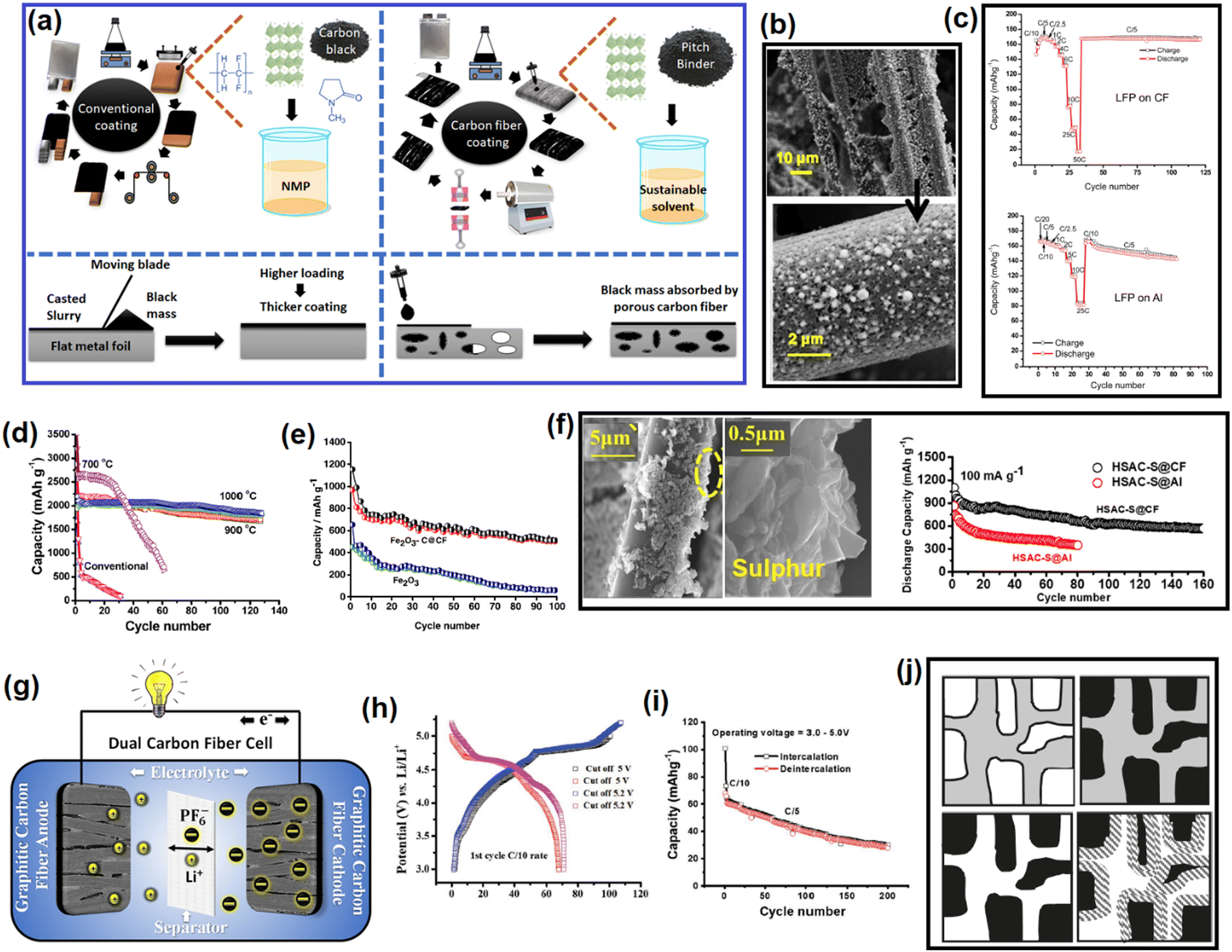 | ||
| Fig. 7 (a) Difference between a conventional coating on 2D metal foils vs. coating on 3D carbon fibers. (b) SEM images of material loading on the carbon fibers. Reused from ref. 165 with permission. Copyright 2023 Elsevier. (c) C-Rate performance comparison between LFP loaded on Al and carbon fiber (CF). Taken from ref. 159 with permission. (d) Cycling performance of Si/C loaded on CF. Reused from ref. 166 with permission. Copyright 2018 American Chemical Society. (e) Cycling performance comparison between Fe2O3vs. Fe2O3@ carbon fiber as an SIB anode. Taken from ref. 165 with permission. Copyright 2023 Elsevier. (f) SEM images of sulfur loaded on carbon fiber and the improvement in the cycling performance with respect to the loading on conventional Al foil. Reused from ref. 162 with permission. Copyright 2023 Elsevier. (g) Schematic diagram of a dual carbon fiber cell that worked on a dual-ion-storing mechanism. (h) and (i) Voltage profile and capacity retention profile of a dual carbon fiber cell. Reused from ref. 114 with permission. Copyright 2021 Wiley. (j) Process of making a hierarchically porous monolithic soft carbon current collector from pitch. Reused from ref. 167 with permission. Copyright 2009 American Chemical Society. | ||
The carbon-fiber-based current collector system is compatible with silicon, sulfur, FeF3, NaVPO4F, LiFePO4, carbons, silicates, and all other active materials except metal oxides.16,169–173 LiFePO4 loaded on carbon fiber reduces the surface side reactions, prolongs the cycle life, and induces a more homogeneous state-of-charge (SOC) even at considerably thicker coatings at a 10C rate.167 The reasons are related to the conductive bridging between the active material and current collector by the soft carbon, thus establishing a good contact and robust adhesion for long-term cycling, Fig. 7b. LFP loaded on CF showed a better C-rate performance than conventional LFP on an Al system, as shown in Fig. 7c. In another work, a free-standing carbon fiber incorporating a Si–C composite showed an improved 1st coulombic efficiency of ∼37% without sacrificing the reversible capacity much.174 A 6–14 nm carbon coating obtained from pitch enhanced the conductivity of Si nanoparticles, provided protection from side reactions, and assisted in maintaining electrical and structural integrity. All these factors contributed to an improved energy density and cycle life (Fig. 7d). Similar positive effects were also observed in an Fe2O3 conversion anode for SIBs173 (Fig. 7e). In addition, the carbon fiber system enhanced the cyclability of a sulfur cathode too (Fig. 7f).170 In 2021, we demonstrated the multifunctional utilization of pitch-coated-carbon fibers in Li-based rechargeable batteries, where a dual carbon fiber battery was fabricated that worked by a dual-ion-storing mechanism as described in Section 4.2, utilizing only pitch-coated graphitic carbon fibers as both the cathode and anode and no other active materials.121 Soft carbon played the role of both a conductive additive and binder here. The pictorial representation of the dual carbon fiber cell is provided in Fig. 7g. It was capable of providing 70 mA h g−1 up to 5.2 V vs. Li+/Li and a healthy capacity retention (Fig. 7h and i).
7. Soft-carbon-based current collectors
Doherty et al. fabricated a meso/micro hierarchically porous carbon monolithic current collector from mesophase pitch via a silica-templated synthesis, which featured graphitic microdomains along with a high surface area. The scheme is illustrated in Fig. 7j. The LiFePO4 material was integrated into it by precursor infiltration and calcination. The system offered promising electrochemical performance.175 Pitch could also be converted into a 3D foam-like structure via a polyurethane template method.176 A foam slab was used for a negative current collector in lead–acid batteries. However, discussion of the electrochemistry of aqueous lead–acid batteries is out of the scope of this review.8. Summary and overview
The carbons that are mostly used for rechargeable batteries are graphite, hard, and soft carbon. Graphite is ordered, whereas hard carbon is turbostratically disordered, while soft carbon is a bridging material, which gives us the flexibility to tune its dis/orderedness. The synthetic tunability also influences other properties, thus providing a gamut of advantages to customize it for multifaceted applications. The basic building block of soft carbon is the large aromatic fused molecules along with short aliphatic linkers that undergo aromatic growth polymerization, polycondensation, and intermolecular rearrangement reactions to form an intermediate liquid-crystalline mesophase, which transforms into an ordered microstructure via vigorous gas release and π–π stacking. The evolution mechanism from the precursor via the mesophase renders unique attributes to the soft carbon product, i.e., optimum and tunable porosity, surface area, carbon-rich backbone with a negligible weight percentage of heteroatoms, crystallinity, flexibility, smoothness, and appreciable electronic conductivity. The exceptional blend of physical properties is exploited in various battery applications, like as an active material, coating agent, flexible matrix, binder, conductive additive, and current collector.Soft carbon fulfills all the requirements of an ideal matrix for conversion/alloying materials, e.g., interfacial cohesion, spatial connection, and structural stability. It is a better matrix than graphite and hard carbon for Si-based anodes. The lower lithiation voltage of graphite and its staging mechanism forces the preferential lithiation of SiOx ahead of graphite, which prompts highly resistive bidirectional diffusional Li+ ions through the SiOx core to the surface and vice versa. In contrast, the partially overlapping lithiation potential of soft carbon and its sloping lithiation profiles regulates the unidirectional flow of Li+ with a low-energy barrier. Polycrystalline soft carbon also surpasses hard carbon as mass transport is facilitated by its better graphitic order. Si/SiOx embedded in soft carbon has also been shown to be industrially viable, and can provide an easy, sustainable, and cost-effective solution for the commercialization of Si-based anodes over chemical vapor-deposited coatings. Soft carbon coating has also been proven to be efficient for Sn/SnO2, Zn3V2O8, and red phosphorous-based anodes in LIBs, SIBs, and KIBs too. It suppresses volume expansion, mitigates material pulverization and electrode delamination, and improves the cycle life. Further, soft carbon is a better mesh for sulfur cathodes than disordered carbon blacks. It enables a higher mass loading and catalyzes reversible sulfur redox, and confines polysulfides into mesopores, which carbon black fails to do.
Soft carbon is the best anode for KIBs as it balances both an intercalation capacity into graphitic microdomains and adsorption capacity from defects. The optimum temperature of pitch pyrolysis has been extensively studied and 1500 °C has been established to be best trade-off between capacitive and diffusive storage. Although hard carbon is widely explored as an SIB anode, the Na+-storage performances of soft carbon anodes do not lag behind. Rather, some researchers counterargue that soft carbon is a better material than hard carbon as an SIB anode. The reversible capacity of soft carbon originates from the sloping region of its voltage profile due to the storage at local defect sites. The exceptional expandability at first sodiation facilitates soft carbon to perform far better in subsequent cycles. It also does not contain the <0.1 V vs. Na+/Na plateau, unlike hard carbon, and is not susceptible to sodium plating. On the other hand, soft carbon is rarely considered as an LIB anode because of the extraordinary performance of graphite. The turbostratic disorder in soft carbon shortens the stage 2 → 1 conversion plateau corresponding to 0.1 V vs. Li+/Li and also prevents the AB → AA stage conversion after lithiation. Nevertheless, composites of graphite and soft carbon can be a good option for fast charging anodes, and graphite–hard carbon composites have already been reported. Soft carbon has recently emerged as a more promising cathode for anion storage. The small graphitic domains circumvent the sluggish transition of the higher to lower stage conversion mechanism of graphite, thereby enhancing the capacity and C-rate performance. However, more in-depth studies are required to support this observation.
Soft carbon is undoubtedly the best coating agent for both the cathode and anode. Commercial graphite comes with a thin soft-carbon coating for surface smoothening. It alleviates electrolyte decomposition at graphene's edges, improves the C-rate by altering the orientation of graphite particles along the direction of the incoming Li+ flux, and modifies the solid–electrolyte interface (SEI) for inorganic-rich compositions due to the abundance of CO groups on the surface of soft carbon. In the case of Ti-based anodes (LTO, TiO2/C, and Na2Ti3O7) for LIBs and SIBs, the major role of the soft carbon coating is to increase the electrical conductivity. For example, 2–5 wt% carbon coating can enhance the electrical conductivity of LTO from 10−9 to 10−3 S cm−1. Carbon coating is also essential for polyanionic cathodes. Indeed, carbon coating has helped make the phosphate cathode a commercial success, as pristine phosphate materials are poor conductors of ions and electrons. The ideal situation is nanosized primary particles of LFP wrapped in a uniform coating, with further clustering into microsized secondary particles. However, it is very difficult to control the thickness, uniformity, and conformity of the coating. Meanwhile, pitch precursors provide that benefit when pitch is added before the sintering stage to obtain an in situ coating. The melted pitch during synthesis hinders undesired particle agglomeration, something which no other carbon precursors can do. This pitch also assists in improving the packing density of the LFP material and the volumetric energy density of LFP-based LIBs. Further, the soft carbon derived from pitch enhances the thermal diffusivity more than the uncoated sample. In addition, pitch outperforms other carbon precursors, like Super P, KS15 and Vulcan-XC72, in the carbothermal synthesis of LVP/C due to its higher reducibility and favorable thermodynamics to be converted into CO2. The obtained electrochemistry is better than the cases where carbon is derived from polymers, carbohydrates, amino acids, or polysaccharides, etc. Similarly, soft carbon has also been reported to be beneficial for all other phosphate-based polyanionic cathodes for LIBs and SIBs. Further, the latest addition in the list of materials that benefits from soft carbon integration is LNMO spinel oxides. Soft carbon furnishes a high voltage protection there, decreases parasitic reactions at the LNMO surface involving the electrolyte, and also decreases Mn dissolution. A similar kind of high voltage protection is also dispensed by soft carbon on anion-storing carbon cathodes. The smoothness, polycrystallinity, porosity, and flexibility of pitch-derived soft carbon partner to provide multifaceted benefits.
Soft carbon also finds uses as a binder and conductive additive for 3D carbon-fiber-based current collectors. It eliminates the need for PVDF binder, the use of NMP solvent, and conductive carbon black in such systems. The viscous nature of the melted mesophase pitch demonstrates binding properties and secures the adhesion of the active material with the carbon fiber. Also, the pitch precursor itself can be transformed into a monolithic current collector by a template synthesis method. The 3D fibrous or foam-type material offers voltage stabilities of 0–5 V vs. Li+/Li. Hence, it can used as both a cathode and anode current collector.
9. Conclusion, outlook, and future perspective
This review compiles literature reports on the wide variety of applications of soft carbon. In the majority of the cases, soft carbon comes out with flying colors when compared to other carbon variants. Therefore, it possesses enormous commercial prospects. In the upcoming years, it may find success as a KIB anode, matrix for conversion/alloying anodes like Si, and coating agent for LMFP and NVP cathodes. The commercial suitability of other applications shown in this article is subject to further developments. Nevertheless, none of the other forms of carbon, like graphite, hard carbon, graphene, and carbon black, have such an extensive domain of applications. Graphite is used as an LIB anode exhaustively and as a conductive additive in few cases. The utilization of carbon black is confined to as a conductive additive only. Graphene is a good fit for capacitor applications mainly. Its usage in batteries is limited to conductive additives or a coating, but in a minute quantity to preserve the volumetric characteristics. SIB prototypes containing hard carbon anodes have been demonstrated and are likely going to enter the consumer market in upcoming years. Besides, there exists lot of ambiguities around the usefulness of hard carbon as its good Na+-storage performance comes with additional disadvantages. In contrast, soft carbon can be tailored for all the above-mentioned applications. Here lies the beauty of soft carbon. That is why, it is not being overoptimistic to state that soft carbon may find multiple applications in the future, especially in batteries.While graphite is naturally available, its availability and cost are based on the supply chain, which itself is dependent on geopolitics. Moreover, the artificial synthesis of graphite is cost-bearing and energy-consuming. But hard and soft carbon syntheses can be performed at lower temperatures than graphite. This production upper hand may impart far reaching consequences in the future production of battery-grade carbon materials. The sources of hard carbon are plentiful, i.e., any available biomass. However, the major hurdle is the reliability and reproducibility of the material. The physical and electrochemical properties vary from one biomass to another, sometimes even between two separate batches of the same biomass. This production obstacle can be circumvented by chemical routes, but again the issues of atom economy and upscalability come into the picture. On the other hand, the precursor options for graphitizable soft carbon are very narrow. It is mainly petroleum and coal derived byproducts, i.e., pitch, pyrolysis fuel oil, anthracite, and a few organic molecules, like PTCDA and naphthalene, vinyl polymers. Pitch is the most used in the literature. It is low cost and a useful precursor for synthetic graphite too. Therefore, putting the environmental issues, like CO2 evolution, aside, the production of soft carbon from a pitch precursor is a useful scheme. Moreover, pitch encompasses a broad class of organic moieties. Based on the solubility in organic solvents, it can be classified into toluene in/solubles, hexane in/solubles, quinoline in/solubles, etc. Each fraction leads to a different category of product that shows completely distinguishable behaviors from others. For example, the quinoline-soluble fraction gives rise to N,S-dual-doped soft carbon. The plethora of choices pitch offers cannot be achieved from any other precursor. In addition, pitch provides one of the highest precursors to carbon conversion yields (not less than 45%), while other precursors struggle to reach >20%. Hence, the uniqueness of pitch-derived soft carbon can be easily comprehended.
Despite several advantages, there are a few remaining challenges for the adoption of soft carbon for widespread battery applications. First, from an electrochemistry point of view, the major shortcomings of using soft carbon as an anode are the low capacity and the irreversibility in the initial cycles. The irreversibility issue can be circumvented by particle engineering approaches, like spheroidizing, or size uniformization. Therefore, future research directions in soft carbon development include the mitigation of irreversibility. However, one positive attribute of commercially available soft carbon is its 1.9–2.1 g cm−3 true density leading to 0.9–1.0 g cm−3 tap density, which is very close to graphite and better than hard carbon. Second, from the perspective of large-scale production, the limited choice of precursors may become a daunting challenge. Petroleum and coal byproducts may not be sustainable, while organic precursors are generally not cost-effective.
In short, this review covers all aspects of soft carbon for use in non-aqueous rechargeable batteries, i.e., from its synthesis, carbonization mechanism, characterizations of physical properties, to all literature reported applications. The ease of synthesis and unique blend of tunable properties makes soft carbon a standout material for multifunctional battery applications.
Author contributions
Shuvajit Ghosh: conceptualization, visualiuzation, data mining, figure drawing and formatting, writing – first draft, writing – review & editing, referencing. Mohammad Zaid: data mining, figure drawing and formatting, writing – first draft. Jyotirekha Dutta: data mining, writing – first draft, referencing. Monira Parvin: data mining, writing – first draft. Surendra K. Martha: supervision, resources, validation, project administration, funding acquisition, writing – review & editing.Conflicts of interest
There are no conflicts of interests to declare.Acknowledgements
SG acknowledges CSIR, Govt. of India (File No. 09/1001(0067)/2019-EMR-I) for the fellowship. MZ acknowledges UGC, Govt. of India (Ref. No.: 211610132554) for the fellowship. JD acknowledges DST-INSPIRE (code: IF200099), Govt. of India for fellowship. MP acknowledges SERB-IRHPA (file no. IPA/2021/000007), Govt. of India for the fellowship. SKM acknowledges DST-SERB (Sanction Order: CRG/2018/003543), Govt. of India, for financial assistance to this work.References
- B. Dolter, Alternatives J., 2017, 43, 32 Search PubMed.
- U. Al-mulali, H. G. Fereidouni and J. Y. M. Lee, Renewable Sustainable Energy Rev., 2014, 30, 290–298 CrossRef.
- G. He, J. Michalek, S. Kar, Q. Chen, D. Zhang and J. F. Whitacre, Joule, 2021, 5, 379–392 CrossRef.
- C. A. Murphy, A. Schleifer and K. Eurek, Renewable Sustainable Energy Rev., 2021, 139, 110711 CrossRef.
- T. M. Gür, Energy Environ. Sci., 2018, 11, 2696–2767 RSC.
- M. Li, J. Lu, Z. Chen and K. Amine, Adv. Mater., 2018, 30, 1800561 CrossRef PubMed.
- S. Choi and G. Wang, Adv Mater. Technol., 2018, 3, 1700376 CrossRef.
- U. Bhattacharjee, S. Ghosh, M. Bhar and S. K. Martha, Emerging Trends in Energy Storage Systems and Industrial Applications, Elsevier, 2023, pp. 151–188 Search PubMed.
- U. Bhattacharjee, S. Ghosh, M. Bhar and S. K. Martha, Emerging Trends in Energy Storage Systems and Industrial Applications, Elsevier, 2023, pp. 595–617 Search PubMed.
- M. Armand, P. Axmann, D. Bresser, M. Copley, K. Edström, C. Ekberg, D. Guyomard, B. Lestriez, P. Novák and M. Petranikova, J. Power Sources, 2020, 479, 228708 CrossRef CAS.
- M. Fichtner, K. Edström, E. Ayerbe, M. Berecibar, A. Bhowmik, I. E. Castelli, S. Clark, R. Dominko, M. Erakca, A. A. Franco, A. Grimaud, B. Horstmann, A. Latz, H. Lorrmann, M. Meeus, R. Narayan, F. Pammer, J. Ruhland, H. Stein, T. Vegge and M. Weil, Adv. Energy Mater., 2022, 12, 2102904 CrossRef CAS.
- S. Ghosh, U. Bhattacharjee, S. Bhowmik and D. S. K. Martha, J. Energy Power Technol., 2022, 4, 1–77 CAS.
- Y. Ahmad, M. Colin, C. Gervillie-Mouravieff, M. Dubois and K. Guérin, Synth. Met., 2021, 280, 116864 CrossRef CAS.
- H. Thiele, Z. Anorg. Allg. Chem., 1932, 207, 340–352 CrossRef CAS.
- U. Hofmann and W. Rüdorff, Trans. Faraday Soc., 1938, 34, 1017–1021 RSC.
- S. K. Martha, L. Elias and S. Ghosh, Silicon Anode Systems for Lithium-Ion Batteries, Elsevier, 2022, pp. 331–371 Search PubMed.
- Y. Fang, X. Yu and X. W. (David) Lou, Angew. Chem., Int. Ed., 2019, 58, 7744–7748 CrossRef CAS PubMed.
- R. Orlando, C. Daniel, W. E. Tenhaeff and S. K. Martha, US Pat., 10, 680, 236, 2020 (Extention of US pat. No. 2014/0038042 A1), 2020.
- S. Li, Y.-M. Liu, Y.-C. Zhang, Y. Song, G.-K. Wang, Y.-X. Liu, Z.-G. Wu, B.-H. Zhong, Y.-J. Zhong and X.-D. Guo, J. Power Sources, 2021, 485, 229331 CrossRef CAS.
- J. Ling, C. Karuppiah, S. G. Krishnan, M. V. Reddy, I. I. Misnon, M. H. Ab Rahim, C.-C. Yang and R. Jose, Energy Fuels, 2021, 35, 10428–10450 CrossRef CAS.
- A. B. Yaroslavtsev and I. A. Stenina, Surface Innovations, 2021, 9, 92–110 CrossRef.
- X. Ding, Q. Zhou, X. Li and X. Xiong, Chem. Commun, 2024, 60, 2472–2488 RSC.
- Z. Zhu, F. Cheng and J. Chen, J. Mater. Chem. A, 2013, 1, 9484–9490 RSC.
- M. Yoshio, H. Wang and K. Fukuda, Angew. Chem., Int. Ed., 2003, 42, 4203–4206 CrossRef CAS PubMed.
- G. Wang, M. Yu and X. Feng, Chem. Soc. Rev., 2021, 50, 2388–2443 RSC.
- V. Gopalakrishnan, A. Sundararajan, P. Omprakash and D. B. Panemangalore, J. Electrochem. Soc., 2021, 168, 040541 CrossRef CAS.
- A. Yoshino, Nat. Energy, 2021, 6, 449 CrossRef CAS.
- F. Xie, Z. Xu, Z. Guo, Y. Lu, L. Chen, M.-M. Titirici and Y.-S. Hu, Sci. China: Chem., 2021, 64, 1679–1692 CrossRef CAS.
- P. Molaiyan, G. S. Dos Reis, D. Karuppiah, C. M. Subramaniyam, F. Garcia-Alvarado and U. Lassi, Batteries, 2023, 9, 116 CrossRef CAS.
- W. Tang, Y. Zhang, Y. Zhong, T. Shen, X. Wang, X. Xia and J. Tu, Mater. Res. Bull., 2017, 88, 234–241 CrossRef CAS.
- J. Ni and Y. Li, Adv. Energy Mater., 2016, 6, 1600278 CrossRef.
- Y. Zhao, Y. Zhang, Y. Wang, D. Cao, X. Sun and H. Zhu, Carbon Energy, 2021, 3, 895–915 CrossRef CAS.
- F. Liu, C. W. Lee and J. S. Im, J. Nanomater., 2013, 2013, 106 CrossRef.
- H. Feng, L. Tang, G. Zeng, J. Tang, Y. Deng, M. Yan, Y. Liu, Y. Zhou, X. Ren and S. Chen, J. Mater. Chem. A, 2018, 6, 7310–7337 RSC.
- S. Chen, L. Qiu and H.-M. Cheng, Chem. Rev., 2020, 120, 2811–2878 CrossRef CAS PubMed.
- R. Raccichini, A. Varzi, S. Passerini and B. Scrosati, Nat. Mater., 2015, 14, 271–279 CrossRef CAS PubMed.
- M. Zeiger, N. Jäckel, V. N. Mochalin and V. Presser, J. Mater. Chem. A, 2016, 4, 3172–3196 RSC.
- T. Liu, L. Zhang, B. Cheng and J. Yu, Adv. Energy Mater., 2019, 9, 1803900 CrossRef.
- X. Dou, I. Hasa, D. Saurel, C. Vaalma, L. Wu, D. Buchholz, D. Bresser, S. Komaba and S. Passerini, Mater. Today, 2019, 23, 87–104 CrossRef CAS.
- S. Ghosh, U. Bhattacharjee, J. Dutta, K. Sairam, R. Korla and S. K. Martha, J. Power Sources, 2023, 584, 233585 CrossRef CAS.
- Z. Jiang, Y. Zhao, X. Lu and J. Xie, J. Energy Chem., 2021, 55, 70–79 CrossRef CAS.
- N. A. Kaskhedikar and J. Maier, Adv. Mater., 2009, 21, 2664–2680 CrossRef CAS PubMed.
- P. Chen, J. N. Metz, A. S. Mennito, S. Merchant, S. E. Smith, M. Siskin, S. P. Rucker, D. C. Dankworth, J. D. Kushnerick and N. Yao, Carbon, 2020, 161, 456–465 CrossRef CAS.
- W. Zhang, J. T. Andersson, H. J. Räder and K. Müllen, Carbon, 2015, 95, 672–680 CrossRef CAS.
- S. Wu, Y. Song, C. Lu, T. Yang, S. Yuan, X. Tian and Z. Liu, Carbon, 2023, 203, 211–220 CrossRef CAS.
- I. C. Lewis, Fuel, 1987, 66, 1527–1531 CrossRef CAS.
- A. L. Lima, K. dos, S. C. Lima, T. C. França, M. I. B. Tavares, R. A. San-Gil, M. N. Eberlin and A. C. Pinto, J. Braz. Chem. Soc., 2012, 23, 1355–1371 CrossRef CAS.
- S. Choi, G. Nam, S. Chae, D. Kim, N. Kim, W. S. Kim, J. Ma, J. Sung, S. M. Han, M. Ko, H. Lee and J. Cho, Adv. Energy Mater., 2019, 9, 1803121 CrossRef.
- B. Xue, J. Xu and R. Xiao, ACS Sustainable Chem. Eng., 2021, 9, 15925–15934 CrossRef CAS.
- J. Entwistle, R. Ge, K. Pardikar, R. Smith and D. Cumming, Renewable Sustainable Energy Rev., 2022, 166, 112624 CrossRef CAS.
- J. Zhang, J. Han, Q. Yun, Q. Li, Y. Long, G. Ling, C. Zhang and Q.-H. Yang, Small Sci., 2021, 1, 2000063 CrossRef CAS.
- K. Feng, M. Li, W. Liu, A. G. Kashkooli, X. Xiao, M. Cai and Z. Chen, Small, 2018, 14, 1702737 CrossRef PubMed.
- The success story of graphite as a lithium-ion anode material – fundamentals, remaining challenges, and recent developments including silicon (oxide) … – Sustainable Energy & Fuels (RSC Publishing) 10.1039/D0SE00175A, https://pubs.rsc.org/en/content/articlehtml/2020/se/d0se00175a, (accessed February 22, 2024).
- C. Zhang, F. Wang, J. Han, S. Bai, J. Tan, J. Liu and F. Li, Small Struct., 2021, 2, 2100009 CrossRef CAS.
- F. Dou, L. Shi, G. Chen and D. Zhang, Electrochem. Energy Rev., 2019, 2, 149–198 CrossRef CAS.
- J. Wu, Y. Cao, H. Zhao, J. Mao and Z. Guo, Carbon Energy, 2019, 1, 57–76 CrossRef CAS.
- Is Soft Carbon a More Suitable Match for SiOx in Li-Ion Battery Anodes? (Small 37/2023) – Sun – 2023 – Small – Wiley Online Library, https://onlinelibrary.wiley.com/doi/abs/10.1002/smll.202370299, (accessed February 22, 2024).
- G. Nava, J. Schwan, M. G. Boebinger, M. T. McDowell and L. Mangolini, Nano Lett., 2019, 19, 7236–7245 CrossRef CAS PubMed.
- Y. He, F. Han, F. Wang, J. Tao, H. Wu, F. Zhang and J. Liu, Electrochim. Acta, 2021, 373, 137924 CrossRef CAS.
- J. Du, J. Ma, Z. Liu, W. Wang, H. Jia, M. Zhang and Y. Nie, RSC Adv., 2022, 12, 20672–20678 RSC.
- S. J. Kim, S.-J. Ha, J. U. Lee, Y.-P. Jeon and J.-Y. Hong, C, 2023, 9, 114 CAS.
- W. Zhang, S. Fang, N. Wang, J. Zhang, B. Shi, Z. Yu and J. Yang, Inorg. Chem. Front., 2020, 7, 2487–2496 RSC.
- A. M. Escamilla-Pérez, A. Roland, S. Giraud, C. Guiraud, H. Virieux, K. Demoulin, Y. Oudart, N. Louvain and L. Monconduit, RSC Adv., 2019, 9, 10546–10553 RSC.
- N. Kobayashi, Y. Inden and M. Endo, J. Power Sources, 2016, 326, 235–241 CrossRef CAS.
- J.-Y. Li, G. Li, J. Zhang, Y.-X. Yin, F.-S. Yue, Q. Xu and Y.-G. Guo, ACS Appl. Mater. Interfaces, 2019, 11, 4057–4064 CrossRef CAS PubMed.
- S. Chae, Y. Xu, R. Yi, H. Lim, D. Velickovic, X. Li, Q. Li, C. Wang and J. Zhang, Adv. Mater., 2021, 33, 2103095 CrossRef CAS PubMed.
- F. Li, Q. Liu, J. Hu, J. Yang and J. Ma, J. Phys. D: Appl. Phys., 2020, 53, 353001 CrossRef CAS.
- Y. Li, R. Liu, C. Wang and Y. Zhou, Energy Fuels, 2021, 35, 9029–9037 CrossRef CAS.
- J. H. Jo, J. U. Choi, H. J. Kim, H. Yashiro and S.-T. Myung, ACS Sustainable Chem. Eng., 2020, 8, 1908–1915 CrossRef CAS.
- W. Liu, H. Zhi and X. Yu, Energy Storage Mater., 2019, 16, 290–322 CrossRef.
- C. Liu, J. Yao, Y. Sun, Y. Zhu, H. Li, D. Feng, H. Li, Y. Yang, Q. Mao and T. Ma, Resources Chem. Mater., 2024, 3, 54–61 CrossRef CAS.
- 3D-hosted lithium metal anodes – Chemical Society Reviews (RSC Publishing), https://pubs.rsc.org/en/content/articlelanding/2024/cs/d3cs00495c, (accessed April 15, 2024).
- Y. Fang, Y. Zeng, Q. Jin, X. F. Lu, D. Luan, X. Zhang and X. W. (David) Lou, Angew. Chem., Int. Ed., 2021, 60, 8515–8520 CrossRef CAS PubMed.
- Y. Fang, S. L. Zhang, Z.-P. Wu, D. Luan and X. W. (David) Lou, Sci. Adv., 2021, 7, eabg3626 CrossRef CAS PubMed.
- Y. Yang, G. Zheng and Y. Cui, Chem. Soc. Rev., 2013, 42, 3018–3032 RSC.
- M. Wang, X. Xia, Y. Zhong, J. Wu, R. Xu, Z. Yao, D. Wang, W. Tang, X. Wang and J. Tu, Chem. – Eur. J., 2019, 25, 3710–3725 CrossRef CAS PubMed.
- H. Mai, Q. Wang, L. Sun, X. Meng, S. Chen, J. Zhou, Y. Jia, M. Wang, X. Han, X. Zhou, W. Gong, G. Zhu, J. Li, C. W. Bielawski and J. Geng, ACS Appl. Mater. Interfaces, 2023, 15, 41426–41437 CrossRef CAS PubMed.
- G. Li, J. Sun, W. Hou, S. Jiang, Y. Huang and J. Geng, Nat. Commun., 2016, 7, 10601 CrossRef CAS PubMed.
- X. Zhou, J. Zhou, L. Sun, S. Chen, M. Wang, X. Meng, J. Qu, C. Sun, Z.-Z. Yu, Y. Huang, C. W. Bielawski and J. Geng, ACS Appl. Energy Mater., 2023, 6, 11157–11167 CrossRef CAS.
- Y.-C. Ko, C.-H. Hsu, C.-A. Lo, C.-M. Wu, H.-L. Yu, C.-H. Hsu, H.-P. Lin, C.-Y. Mou and H.-L. Wu, ACS Sustainable Chem. Eng., 2022, 10, 4462–4472 CrossRef CAS.
- G. D. Park, D. S. Jung, J.-K. Lee and Y. C. Kang, Chem. Eng. J., 2019, 373, 382–392 CrossRef CAS.
- C. Schafhaeutl, J. Prakt. Chem., 1840, 21, 129–157 CrossRef.
- C. Li, L. Yan, M. Wang, J. Kong, W. Bao and L. Chang, Chem. Record, 2023, 23, e202200216 CrossRef CAS PubMed.
- S. Wu, Y. Song, C. Lu, T. Yang, S. Yuan, X. Tian and Z. Liu, Small, 2022, 18, 2105275 CrossRef CAS PubMed.
- W. Ruland and B. Smarsly, J. Appl. Crystallogr., 2004, 37, 575–584 CrossRef CAS.
- A. Monshi, M. R. Foroughi and M. R. Monshi, World J. Nano Sci. Eng., 2012, 2, 154–160 CrossRef.
- C. G. Pope, J. Chem. Educ., 1997, 74, 129 CrossRef CAS.
- F. R. Feret, Analyst, 1998, 123, 595–600 RSC.
- F. Aune, W. Brockner and H. A. Øte, Carbon, 1992, 30, 1001–1005 CrossRef CAS.
- M. Ou, Y. Zhang, Y. Zhu, C. Fan, S. Sun, J. Feng, X. Sun, P. Wei, J. Xu, J. Peng, X. Wu, G. Jiang, Q. Li, C. Fang and J. Han, ACS Appl. Mater. Interfaces, 2021, 13, 28261–28269 CrossRef CAS PubMed.
- D. B. Schuepfer, F. Badaczewski, J. M. Guerra-Castro, D. M. Hofmann, C. Heiliger, B. Smarsly and P. J. Klar, Carbon, 2020, 161, 359–372 CrossRef CAS.
- F. Ricciardella, E. Massera, T. Polichetti, M. L. Miglietta and G. Di Francia, Appl. Phys. Lett, 2014, 104, 183502 CrossRef.
- R. Alcántara, G. F. Ortiz, P. Lavela, J. L. Tirado, R. Stoyanova and E. Zhecheva, Chem. Mater., 2006, 18, 2293–2301 CrossRef.
- D. Tomaszewski and K. Tadyszak, Materials, 2022, 15, 4964 CrossRef CAS PubMed.
- D. Saurel, J. Segalini, M. Jauregui, A. Pendashteh, B. Daffos, P. Simon and M. Casas-Cabanas, Energy Storage Mater., 2019, 21, 162–173 CrossRef.
- W. Jian, X. Qiu, Y. Lai, P. Yin, J. Lin and W. Zhang, Adv. Energy Mater., 2023, 13, 2301303 CrossRef CAS.
- X. Chen, X. Wang and D. Fang, Fullerenes, Nanotubes Carbon Nanostruct., 2020, 28, 1048–1058 CrossRef CAS.
- B. Watts, L. Thomsen and P. C. Dastoor, J. Electron Spectrosc. Relat. Phenom., 2006, 151, 105–120 CrossRef CAS.
- A. T. Kozakov, A. G. Kochur, N. Kumar, K. Panda, A. V. Nikolskii and A. V. Sidashov, Appl. Surf. Sci., 2021, 536, 147807 CrossRef CAS.
- Y. Jiang, J. Jiang, P. Nie, W. Guo, C. Geng, Z. Sun, Y. Fei, Y. Chen, Q. Zhuang and Z. Xing, J. Energy Storage, 2023, 72, 108484 CrossRef.
- H. Tan, R. Zhou and B. Zhang, J. Power Sources, 2021, 506, 230179 CrossRef CAS.
- Z. Sun, Y. Chen, B. Xi, C. Geng, W. Guo, Q. Zhuang, X. An, J. Liu, Z. Ju and S. Xiong, Energy Storage Mater., 2022, 53, 482–491 CrossRef.
- C. Liu, H. Zheng, Y. Wang, N. Xiao, K. Yu, H. Li, X. Zhang, H. Bai, T. Ma and J. Qiu, J. Colloid Interface Sci., 2022, 615, 485–493 CrossRef CAS PubMed.
- Q. Liu, F. Han, J. Zhou, Y. Li, L. Chen, F. Zhang, D. Zhou, C. Ye, J. Yang, X. Wu and J. Liu, ACS Appl. Mater. Interfaces, 2020, 12, 20838–20848 CrossRef CAS PubMed.
- K. Hong, L. Qie, R. Zeng, Z. Yi, W. Zhang, D. Wang, W. Yin, C. Wu, Q. Fan and W. Zhang, J. Mater. Chem. A, 2014, 2, 12733–12738 RSC.
- D. A. Stevens and J. R. Dahn, J. Electrochem. Soc., 2001, 148, A803 CrossRef CAS.
- H. Au, H. Alptekin, A. C. Jensen, E. Olsson, C. A. O’Keefe, T. Smith, M. Crespo-Ribadeneyra, T. F. Headen, C. P. Grey and Q. Cai, Energy Environ. Sci., 2020, 13, 3469–3479 RSC.
- Y. Morikawa, S. Nishimura, R. Hashimoto, M. Ohnuma and A. Yamada, Adv. Energy Mater., 2020, 10, 1903176 CrossRef CAS.
- S. Ghosh, V. K. Kumar, S. K. Kumar, U. Sunkari, S. Biswas and S. K. Martha, Electrochim. Acta, 2020, 353, 136566 CrossRef CAS.
- Z. Jian, C. Bommier, L. Luo, Z. Li, W. Wang, C. Wang, P. A. Greaney and X. Ji, Chem. Mater., 2017, 29, 2314–2320 CrossRef CAS.
- W. Luo, Z. Jian, Z. Xing, W. Wang, C. Bommier, M. M. Lerner and X. Ji, ACS Cent. Sci., 2015, 1, 516–522 CrossRef CAS PubMed.
- Y. Miao, J. Zong and X. Liu, Mater. Lett., 2017, 188, 355–358 CrossRef CAS.
- Y. Li, Y.-S. Hu, X. Qi, X. Rong, H. Li, X. Huang and L. Chen, Energy Storage Mater., 2016, 5, 191–197 CrossRef.
- X. Yao, Y. Ke, W. Ren, X. Wang, F. Xiong, W. Yang, M. Qin, Q. Li and L. Mai, Adv. Energy Mater., 2019, 9, 1803260 CrossRef.
- X. Li, H. Zhao, C. Zhang, B. Xing, C. Zhang and C. Zhou, J. Mater. Sci.: Mater. Electron., 2021, 32, 21944–21956 CrossRef CAS.
- H. Chen, N. Sun, Y. Wang, R. A. Soomro and B. Xu, Energy Storage Mater., 2023, 56, 532–541 CrossRef.
- N. Sick, O. Krätzig, G. G. Eshetu and E. Figgemeier, J. Energy Storage, 2021, 43, 103231 CrossRef.
- T. Zheng, J. N. Reimers and J. R. Dahn, Phys. Rev. B: Condens. Matter Mater. Phys., 1995, 51, 734–741 CrossRef CAS PubMed.
- W. Lu and D. D. L. Chung, Carbon, 2003, 41, 945–950 CrossRef CAS.
- S. Ghosh, D. Sarma, A. Mahata and S. K. Martha, J. Power Sources, 2024, 589, 233721 CrossRef CAS.
- S. Ghosh, U. Bhattacharjee, S. Patchaiyappan, J. Nanda, N. J. Dudney and S. K. Martha, Adv. Energy Mater., 2021, 11, 2100135 CrossRef CAS.
- S. Ghosh and S. K. Martha, J. Energy Storage, 2024, 77, 109866 CrossRef.
- S. Ghosh and S. K. Martha, J. Energy Storage, 2023, 74, 109491 CrossRef.
- S. Ghosh, M. P. Nihad, S. Muduli, S. Bhowmik and S. K. Martha, Electrochim. Acta, 2023, 441, 141754 CrossRef CAS.
- A. Heckmann, O. Fromm, U. Rodehorst, P. Münster, M. Winter and T. Placke, Carbon, 2018, 131, 201–212 CrossRef CAS.
- Y. Shen, M. Zhang, D. Yan, J. Lv, T. Wu, B. He and W. Li, ChemSusChem, 2023, 16, e202300493 CrossRef CAS PubMed.
- S. Yoon, H. Kim and S. M. Oh, J. Power Sources, 2001, 94, 68–73 CrossRef CAS.
- Y. J. Jo and J. D. Lee, Korean J. Chem. Eng., 2019, 36, 1724–1731 CrossRef CAS.
- Y.-J. Han, J. Kim, J.-S. Yeo, J. C. An, I.-P. Hong, K. Nakabayashi, J. Miyawaki, J.-D. Jung and S.-H. Yoon, Carbon, 2015, 94, 432–438 CrossRef CAS.
- B.-R. Kim, J.-H. Kim and J.-S. Im, Materials, 2022, 15, 4713 CrossRef CAS PubMed.
- B. Zheng, W. Zhou, H. Liu, S. Chen, P. Gao, Z. Wang and J. Liu, Carbon, 2024, 218, 118729 CrossRef CAS.
- C. P. Sandhya, B. John and C. Gouri, Ionics, 2014, 20, 601–620 CrossRef CAS.
- H.-G. Jung, J. Kim, B. Scrosati and Y.-K. Sun, J. Power Sources, 2011, 196, 7763–7766 CrossRef CAS.
- S. Ghosh, V. K. Kumar, S. K. Kumar, S. Biswas and S. K. Martha, Electrochim. Acta, 2019, 316, 69–78 CrossRef CAS.
- K.-T. Kim, G. Ali, K. Y. Chung, C. S. Yoon, H. Yashiro, Y.-K. Sun, J. Lu, K. Amine and S.-T. Myung, Nano Lett., 2014, 14, 416–422 CrossRef CAS PubMed.
- P. Senguttuvan, G. Rousse, V. Seznec, J.-M. Tarascon and M. R. Palacín, Chem. Mater., 2011, 23, 4109–4111 CrossRef CAS.
- S. Li, S. Wen, H. Ding, L. Yang, D. Zhao, N. Zhang, H. Dong, S. Wang, J. Zhang and J. Wang, ACS Sustainable Chem. Eng., 2022, 10, 4247–4257 CrossRef CAS.
- P. Barpanda, G. Liu, C. D. Ling, M. Tamaru, M. Avdeev, S.-C. Chung, Y. Yamada and A. Yamada, Chem. Mater., 2013, 25, 3480–3487 CrossRef CAS.
- S. Ghosh, N. Barman, M. Mazumder, S. K. Pati, G. Rousse and P. Senguttuvan, Adv. Energy Mater., 2020, 10, 1902918 CrossRef CAS.
- J. Wang and X. Sun, Energy Environ. Sci., 2012, 5, 5163–5185 RSC.
- S. W. Oh, S.-T. Myung, H. J. Bang, C. S. Yoon, K. Amine and Y.-K. Sun, Electrochem. Solid-State Lett., 2009, 12, A181 CrossRef CAS.
- S. W. Oh, S. Myung, S. Oh, K. H. Oh, K. Amine, B. Scrosati and Y. Sun, Adv. Mater., 2010, 22, 4842–4845 CrossRef CAS PubMed.
- J. Nanda, S. K. Martha, W. D. Porter, H. Wang, N. J. Dudney, M. D. Radin and D. J. Siegel, J. Power Sources, 2014, 251, 8–13 CrossRef CAS.
- S. K. Martha, B. Markovsky, J. Grinblat, Y. Gofer, O. Haik, E. Zinigrad, D. Aurbach, T. Drezen, D. Wang and G. Deghenghi, J. Electrochem. Soc., 2009, 156, A541 CrossRef CAS.
- S. K. Martha, J. Grinblat, O. Haik, E. Zinigrad, T. Drezen, J. H. Miners, I. Exnar, A. Kay, B. Markovsky and D. Aurbach, Angew. Chem., Int. Ed., 2009, 48, 8559–8563 CrossRef CAS PubMed.
- Z. Song, S. Chen, S. Du and C. Fan, J. Alloys Compd., 2022, 927, 166921 CrossRef CAS.
- X. Rui, Q. Yan, M. Skyllas-Kazacos and T. M. Lim, J. Power Sources, 2014, 258, 19–38 CrossRef CAS.
- Study on Li3V2(PO4)3/C cathode materials prepared using pitch as a new carbon source by different approaches – ScienceDirect, https://www.sciencedirect.com/science/article/pii/S0013468615308082, (accessed February 22, 2024).
- J.-S. Park, J. Kim, W. B. Park, Y.-K. Sun and S.-T. Myung, ACS Appl. Mater. Interfaces, 2017, 9, 40307–40316 CrossRef CAS PubMed.
- The advent of manganese-substituted sodium vanadium phosphate-based cathodes for sodium-ion batteries and their current progress: a focused review – Journal of Materials Chemistry A (RSC Publishing) 10.1039/D1TA09040B, https://pubs.rsc.org/en/content/articlehtml/2022/ta/d1ta09040b, (accessed February 22, 2024).
- V. K. Kumar, S. Ghosh, S. Biswas and S. K. Martha, ACS Appl. Energy Mater., 2021, 4, 4059–4069 CrossRef CAS.
- Synthesis and characterization of nano-Li1.95FeSiO4/C composite as cathode material for lithium-ion batteries – ScienceDirect, https://www.sciencedirect.com/science/article/pii/S0013468611017270, (accessed February 22, 2024).
- M. Saito, S. Yano, T. Maekawa, A. Tasaka and M. Inaba, ECS Trans., 2013, 50, 251 CrossRef.
- H.-M. Cheng, H.-G. Dai, F.-M. Wang, P.-C. Tsai and W.-R. Liu, Int. J. Electrochem. Sci., 2017, 12, 10981–10993 CrossRef CAS.
- X. Huang, X. Li, H. Wang, Z. Pan, M. Qu and Z. Yu, Solid State Ionics, 2010, 181, 1451–1455 CrossRef CAS.
- Developing high-voltage spinel LiNi0.5Mn1.5O4 cathodes for high-energy-density lithium-ion batteries: current achievements and future prospects – Journal of Materials Chemistry A (RSC Publishing) 10.1039/D0TA02812F, https://pubs.rsc.org/en/content/articlehtml/2020/ta/d0ta02812f, (accessed February 22, 2024).
- X. Xu, S. Deng, H. Wang, J. Liu and H. Yan, Nano-Micro Lett., 2017, 9, 22 CrossRef PubMed.
- R. Jung, M. Metzger, F. Maglia, C. Stinner and H. A. Gasteiger, J. Phys. Chem. Lett., 2017, 8, 4820–4825 CrossRef CAS PubMed.
- A Perspective on Coatings to Stabilize High-Voltage Cathodes: LiMn1.5Ni0.5O4 with Sub-Nanometer Lipon Cycled with LiPF6 Electrolyte – IOPscience, https://iopscience.iop.org/article/10.1149/2.017305jes/meta, (accessed February 22, 2024).
- S. Ghosh, M. Mahapatra, S. Bhowmik, K. K. Garlapati and S. K. Martha, ACS Appl. Energy Mater., 2023, 6, 9390–9399 CrossRef CAS.
- M. Wang and Y. Tang, Adv. Energy Mater., 2018, 8, 1703320 CrossRef.
- Li4Ti5O12-coated graphite anode materials for lithium-ion batteries – ScienceDirect, https://www.sciencedirect.com/science/article/pii/S0013468613016800, (accessed February 22, 2024).
- Y. Yue and H. Liang, Small Methods, 2018, 2, 1800056 CrossRef.
- Current Collectors for Flexible Lithium Ion Batteries: A Review of Materials, https://www.jecst.org/journal/view.php?doi=10.5229/JECST.2015.6.1.1, (accessed February 22, 2024).
- M. J. Herzog, N. Gauquelin, D. Esken, J. Verbeeck and J. Janek, Energy Technol., 2021, 9, 2100028 CrossRef CAS.
- Aqueous PVDF slurry for lithium ion battery and its preparation method and use method, China, Current Assignee, Shenzhen Chaoyi New Energy Technology Co. Ltd., China, CN105119000A, 2015.
- S. K. Martha, J. O. Kiggans, J. Nanda and N. J. Dudney, J. Electrochem. Soc., 2011, 158, A1060 CrossRef CAS.
- S. K. Martha, N. J. Dudney, J. O. Kiggans and J. Nanda, J. Electrochem. Soc., 2012, 159, A1652 CrossRef CAS.
- O. Rios, C. Daniel, W. E. Tenhaeff and S. K. Martha, High capacity monolithic composite Si/carbon fiber electrode architectures synthesized from low cost materials and process technologies, Oak Ridge National Laboratory (ORNL), Oak Ridge, TN (United States), 2018 Search PubMed.
- J. P. Grace, M. Bhar, S. Ghosh and S. K. Martha, J. Alloys Compd., 2023, 969, 172341 CrossRef CAS.
- S. K. Martha, J. Nanda, H. Zhou, J. C. Idrobo, N. J. Dudney, S. Pannala, S. Dai, J. Wang and P. V. Braun, RSC Adv., 2014, 4, 6730 RSC.
- S. K. Kumar, S. Ghosh, M. Bhar, A. K. Kavala, S. Patchaiyappan and S. K. Martha, Electrochim. Acta, 2021, 373, 137911 CrossRef CAS.
- M. Bhar, S. Ghosh and S. K. Martha, J. Alloys Compd., 2023, 948, 169670 CrossRef CAS.
- S. K. Kumar, S. Ghosh, S. K. Malladi, J. Nanda and S. K. Martha, ACS Omega, 2018, 3, 9598–9606 CrossRef CAS PubMed.
- C. M. Doherty, R. A. Caruso, B. M. Smarsly, P. Adelhelm and C. J. Drummond, Chem. Mater., 2009, 21, 5300–5306 CrossRef CAS.
- Y. Chen, B.-Z. Chen, X.-C. Shi, H. Xu, W. Shang, Y. Yuan and L.-P. Xiao, Electrochim. Acta, 2008, 53, 2245–2249 CrossRef CAS.
| This journal is © The Royal Society of Chemistry 2024 |