 Open Access Article
Creative Commons Attribution 3.0 Unported Licence
In situ polymerization of EDOT onto sulfonated onion-like carbon for efficient pseudocapacitor electrodes†
Christian
Bauer
a,
Maximilian
Kirchner
ab and
Anke
Krueger
 *ab
*ab
aInstitute for Organic Chemistry, Julius-Maximilians University Würzburg, Am Hubland, 97074 Würzburg, Germany. E-mail: anke.krueger@oc.uni-stuttgart.de
bInstitute of Organic Chemistry, University of Stuttgart, Pfaffenwaldring 55, 70569 Stuttgart, Germany
First published on 3rd May 2024
Abstract
Conductive polymers (CPs) and carbon nanoparticles are attractive active materials for binder free supercapacitor electrodes. A composite of these components combines high pseudocapacitance of CPs with the mechanical stability of carbon particles. Homogeneous percolation of both materials in the composite is fundamental for electrochemical performance but is typically hindered due to insoluble starting materials. Here, we propose a template assisted polymerization of 3,4-ethylenedioxythiophene (EDOT) onto sulfophenylated onion-like carbon (SPOLC). Besides providing dispersibility for the carbon particles, anionic functionalization also promotes the mechanical and electrical connection between PEDOT and SPOLC. The resulting composite precipitates as a viscoelastic aqueous slurry enabling direct processing to binder-free supercapacitor electrodes. The synergistic combination of mechanical and electrochemical properties in the composite leads to a specific capacitance of 77 F g−1 and a capacitance retention above 90% after 70![[thin space (1/6-em)]](https://www.rsc.org/images/entities/char_2009.gif) 000 cycles. Our findings highlight how the functionalization of carbon enhances dispersibility in water and provides connectivity with the CP, thereby boosting the performance and stability in supercapacitor applications.
000 cycles. Our findings highlight how the functionalization of carbon enhances dispersibility in water and provides connectivity with the CP, thereby boosting the performance and stability in supercapacitor applications.
Introduction
Conductive polymers (CPs) are used as active materials for supercapacitors due to their convenient synthesis, electrochemical stability, and intrinsic capacitance.1 The charge storage capability of CPs originates mainly from faradaic but also from non-faradaic processes. The formation of a double layer at the solid–liquid interface between the CP and the electrolyte represents the non-faradaic part. The faradaic component, also called pseudocapacitance, is attributed to redox reactions of the CPs. Due to limited specific porosity of CPs, the contribution of pseudocapacitance towards energy storage exceeds the non-faradaic component.2 In this context, CPs such as polyaniline (PANI), polypyrrole (PPy), and poly(3,4-ethylenedioxythiophene) (PEDOT) are often used for pseudocapacitor applications. Among these CPs, PEDOT offers a superior cyclic stability and an outstanding resilience of its oxidized state, which enables application in a wide potential window.1Despite their electrochemical stability, CPs lack inherent mechanical strength. When used in electrodes for supercapacitors, swelling and shrinking induced by cycling initiates crack formation resulting in degrading capacitance.3 This drawback is often addressed by the addition of nanoparticles, which act as a framework to provide mechanical strength and space for swelling due to open porosity. For this purpose, various nanoparticles like MXenes,4 ZnO nanowires,5 nanofibers,6 carbon nanotubes,7 graphene8 and onion-like carbon9 have been combined with CPs. Carbon particles are ideal because of their sustainability, abundance, electrical conductivity and capability to contribute non-faradaic capacitance.3
To yield a superior composite electrode, the contradicting requirements of a stable coupling between PEDOT and carbon particle while maintaining their dispersibility during the formation of the composite need to be addressed. Both requirements are vital, with the tight interconnection between the particles as a gateway for the electrical current and their dispersibility assuring percolation of the PEDOT network throughout the forming composite. However, neither carbon nanoparticles nor PEDOT are easily dispersible.3
The most convenient approach to enable PEDOT dispersibility is to link it ionically with polystyrene sulfonate (PSS).3 These PEDOT:PSS micelles can be used to adsorb onto the carbon particles, which was reported for onion-like carbon (OLC) by Plonska–Brzezinska et al., enabling the application in electrodes for supercapacitors with a maximum capacitance of 75 F g−1.9b However, as the charge of PEDOT is neutralized by the interaction with sulfonic acid groups of PSS, excess amounts of the latter are required to maintain dispersibility of PEDOT:PSS.3
Another possibility is to establish CP monomers at the surface of the carbon material prior to polymerization. This in situ approach can either be promoted by electrodeposition or by chemical reactions. Electrodeposition is well controllable but also requires charged carbon particles for co-deposition and a specialized setup.8 Chemical oxidation is a more facile method that does not need specific equipment, additionally offering high yields but also requiring a stable carbon dispersion.3
Here we report an efficient approach to integrate and connect PEDOT with carbon particles, i.e. carbon onions, to form a composite suitable for the application in supercapacitor electrodes. Inspired by the functionality of PEDOT:PSS, we designed carbon nanoparticles directly decorated with benzenesulfonic groups. Sulfonation of carbon onions provides not only superior dispersibility but also the binding sites for PEDOT formed upon oxidative in situ polymerization of EDOT. This enables the template assisted precipitation of the PEDOT molecules and thus a homogeneous distribution in the composite without the formation of insulating PSS domains. In the electrode, the OLC template offers a large accessible surface area and mechanical stability while PEDOT enhances the specific capacitance and connects OLC agglomerates. Based on these findings, the composite can be used as active material for supercapacitor electrodes without additional binder.
Experimental
Sulfonation of OLC and composite formation
Composite formation
The onion-like carbon material was then used to form composites with PEDOT. To vary the content of benzenesulfonic acid moieties in the composite, SPOLC, pristine OLC as well as a mixture of both were used as carbon template. Based on these templates, three composites PEDOT@OLC (Fig. 1A) PEDOT@SPOLC (Fig. 1B) and PEDOT@SPOLC/OLC (Fig. 1C) were produced. A detailed synthetic procedure for the different composites can be found in the ESI.†Fabrication of electrodes and supercapacitors
For the slurry, 50 mg of washed PEDOT@SPOLC, PEDOT@SPOLC/OLC or PEDOT@OLC precipitate was stirred with water (100 mg). To obtain electrodes, the respective slurry was doctor bladed onto a carbon coated aluminum foil (Zflo 2653, Transcontinental Advanced Coatings), dried at ambient conditions for 15 minutes and transferred into a drying furnace (130 °C) for about 12 hours, leading to a loading density of about 1.5 mg cm−2. Round electrodes with a diameter of 16 mm were die cut with a punching iron and pressed with a hydraulic press (ca. 0.2 GPa). Symmetrical cells were produced using a stainless-steel test cell separated by a polymer membrane (Cellgard 2325, El-Cell). The electrolyte was prepared as a 1 M solution of tetraethylammonium tetra-fluoroborate (TEABF4; TCI) in acetonitrile (Sigma Aldrich). Three test cells for each system were assembled in the absence of humidity (<1 ppm) and oxygen (<1 ppm) using a glovebox (N2, Labmaster 130, M. Braun Inertgas-Systeme).Characterization
The Raman spectra were acquired with a DXR Raman Microscope (Thermo Fisher Scientific Inc) using a laser power of 0.2 mW and an excitation wavelength of 532 nm. Thermogravimetric analysis (TGA) was carried out with a STA 6000 (PerkinElmer) using nitrogen as purge gas (20 L min−1), a heating rate of 5 K min−1 and a plateau phase of 30 minutes at 130 °C to remove residual water. HRTEM was conducted with a FEI Titan 80–300 (Thermo Fischer Scientific Inc) using an operating voltage of 300 kV. Scanning electron microscopy (SEM) images were measured at an operating voltage of 5 kV using a Gemini Fe-SEM Ultra-Plus Zeiss field emission scanning electron microscope (Carl Zeiss Microscopy Deutschland GmbH). Cyclic voltammetry measurements (CV) were carried out with a potentio-/galvanostat (VMP300 Bio-Logic). Electrochemical measurements were conducted in a symmetrical supercapacitor setup. Every composite system was measured in three test cells at ambient conditions. For each applied scan rate the arithmetic average of ten consecutive cycles was used to calculate the total capacitance of the device CCV (eqn (1)) as well as the specific capacitance for one electrode CE (eqn (2)) where m is the combined mass of carbon material and PEDOT, I the current and V0 the potential window and v the scan rate.One cycle consists of a charge and a discharge process for every electrode, achieved by a repolarization between −V0 and V0.
 | (1) |
 | (2) |
Results and discussion
Characterization of the composite material
Functionalization of carbon particles is vital to ensure their dispersibility in aqueous media as well as for in situ incorporation of EDOT. Surface functionalization with benzenesulfonic acid groups meets both criteria, as the hydrophilic character of the sulfonic acid stabilizes the particles in aqueous media and the anionic charge electrostatically attracts PEDOT tightly to the surface of the OLC particle. As the functionalization occurs on carbon surfaces, Raman microscopy is well suited to identify these changes due to characteristic modes (Fig. 2 and Table 1).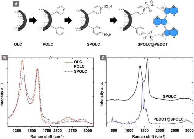 | ||
| Fig. 2 Schematic overview for the precursor functionalization (A), Raman spectra of the particles before (B) and after (C) PEDOT functionalization. | ||
| G-mode (cm−1) | D-mode (cm−1) | 2D-mode (cm−1) | I D/IG | I 2D/IG | |
|---|---|---|---|---|---|
| OLC | 1588 | 1338 | 2670 | 1.17 | 0.12 |
| POLC | 1598 | 1345 | 2681 | 1.06 | 0.09 |
| SPOLC | 1600 | 1357 | 2684 | 0.84 | 0.05 |
The structural changes after each functionalization step are observable by Raman spectroscopy in the characteristic modes for sp2 carbon, i.e. D, G and 2D bands. The G-mode is characteristic for the graphitic structure of the material, whereas the D-mode indicates disorder in the graphitic structure. During surface functionalization of OLC, the intensity ratio of D/G decreases with the surface functionalization of OLC (ID/IG = 1.17) to POLC (ID/IG = 1.06) and SPOLC (ID/IG = 0.84) indicating an influence of functional groups. The change in intensity ratio was already reported for other covalent OLC functionalizations, which included phenolic groups.12 The symmetric shape of the 2D-mode indicates the typical turbostratic stacking of the graphitic layers in OLC.13
Unlike the starting material (OLC) and POLC, SPOLC was highly dispersible in water due to its hydrophilic functionalization, forming a concentrated black, ink-like suspension. For the formation of the composites, PEDOT was established at the carbon particles OLC and SPOLC and a mixture of SPOLC/OLC by addition of EDOT and its in situ polymerization yielding the composites PEDOT@OLC, PEDOT@SPOLC and PEDOT@SPOLC/OLC. The successful formation of PEDOT at the carbon surfaces is apparent by very intense signals in the Raman spectra, overshadowing characteristic signals for SPOLC (Fig. 2B), PEDOT without carbon additive and the three composites PEDOT@OLC (Fig. 1A), PEDOT@SPOLC (Fig. 1B) and PEDOT@SPOLC/OLC (Fig. 1C) showed no significant difference in Raman shift (Fig. S1 and Table S1, ESI†).
To explain the scaffolding effect, which is responsible for the different arrangements of PEDOT in the SPOLC and unfunctionalized OLC, HRTEM measurements were conducted for both composites (Fig. 3).
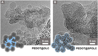 | ||
| Fig. 3 HRTEM micrographs of (A) PEDOT@OLC, (B) PEDOT@SPOLC and schematic interpretation, blue structures represent PEDOT. | ||
In PEDOT@OLC, the PEDOT is concentrated heterogeneously in bigger bulks between voids in the agglomerate leaving single OLC primary participles widely uncoated (Fig. 3A). In contrast, functionalized particles of SPOLC are evenly coated with PEDOT (Fig. 3B). However, as the typical domain size of PEDOT amounts to only several nm,14 the non-uniform coating was not detectable using SEM or Raman microscopy. Consequently, EDX mapping, performed to trace PEDOT, also showed a largely homogeneous sulfur distribution (Fig. S2, ESI†).
The difference in morphology between PEDOT@OLC and PEDOT@SPOLC visible in the HRTEM measurements can be explained by the mechanism of the reaction. Like PEDOT:PSS, oxidized PEDOT oligomers are attracted by counterions during polymerization.15 For the PEDOT@SPOLC system, benzenesulfonic acid moieties present at the surface of the carbon onions act as counterion, binding the PEDOT oligomer at the surface of the carbon particles electrostatically and thus inducing a “guiding” or “scaffolding effect” for the polymerization. Thus, after polymerization, SPOLC agglomerates are homogeneously covered with PEDOT. The interaction with the functional surface groups neutralizes the charge of the composite leading to its precipitation.
For the PEDOT@OLC this electrostatic interaction between SO3− and PEDOT is not possible, as the carbon particle lacks counterions at its surface. Instead, PEDOT oligomers interact with sulfonic acid anions, provided by the decomposition of the oxidative agent (sodium persulfate) during the oxidation of EDOT. Benzenesulfonic acid stabilized PEDOT particles grow in solution, eventually co-precipitating with the agglomerates of OLC. Precipitation eventually occurs for the PEDOT@OLC system because unfunctionalized OLC particles are generally unable to form stable aqueous dispersions. For the mixed composite consisting of functionalized and unfunctionalized OLC particles (PEDOT@SPOLC/OLC) it follows that both types of PEDOT deposition take place.
While PEDOT:PSS systems in the literature retain their dispersibility in aqueous media due to excess benzenesulfonic acid groups, all our composites were precipitating in water forming viscoelastic pastes. This property was beneficial since the composite pastes could be used for electrode production by doctor blading without further processing or the addition of thickening agents like binders.
Besides, the mechanical properties of PEDOT@SPOLC electrodes showed superior stability during electrode manufacturing. Processing of PEDOT@OLC on the other hand, was unsatisfying due to the formation of cracks and delamination of the coating (Fig. S3, ESI†). These drawbacks were observed neither for PEDOT@SPOLC nor for PEDOT@SPOLC/OLC composites, although, for the latter, functionalized and unfunctionalized OLC were mixed in equal amounts prior to the polymerization of EDOT.
This can be explained by the morphology of PEDOT at the surface of carbon particles, or more precisely at the surface of their agglomerates. In PEDOT@SPOLC, PEDOT is evenly distributed over the whole surface and can interact with other neighboring agglomerates, especially while the coating is drying and compressed. The result is a superior inter-agglomerate binding compared to PEDOT@OLC, where PEDOT is concentrated in voids of agglomerates, which hinders inter-agglomerate linkage. Therefore, PEDOT@OLC is not suitable for electrode production due to the formation of cracks. These findings show that the quality of the composite is determined rather by the interaction and distribution of PEDOT and the carbon particles than by its actual relative content. This is not only of importance for a system where PEDOT serves as capacitive enhancing additive, but also in case of its application as a conductive binder,16 where a tailored distribution and superior connection can reduce its content to a minimum.
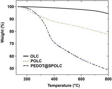
The thermal stability of the composite is an important parameter influencing the possible operating temperature for the intended application. In order to test the thermal properties of the composite, thermogravimetric analysis (TGA) was performed under nitrogen atmosphere (Fig. 4).
A significant loss in weight for PEDOT@SPOLC, was recorded between 260 and 400 °C, representing the degradation typically observed in composites of PEDOT films and carbon.17–19 No weight loss was observed for the starting material OLC, as expected by the absence of surface groups and the temperature resistance of OLC in nitrogen atmosphere. Given this reasonable thermal stability, PEDOT@SPOLC is useable for various applications including electrodes for supercapacitors.20
Electrochemical characterization
The functionalization of OLC is not only beneficial for mechanical but also for electrical interaction between PEDOT and the carbon material. The homogeneous distribution of PEDOT and its tight connection to carbon particles influences energy storage as well as performance capabilities.21 These properties were investigated by cyclic voltammetry measurements for PEDOT@SPOLC and PEDOT@SPOL/OLC, which feature functional groups. With PEDOT@OLC, eligible electrodes could not be produced due to its unsatisfactory mechanical properties (see above).A cyclic voltammogram for pristine PEDOT consists of a capacitive and pseudocapacitive current, explained in detail by Volkov et al.14 The pseudocapacitance in CPs originates from redox reactions, where cations are replaced by holes for an anodic scan and vice versa for the cathodic reversal. The non-faradaic contribution is caused by the formation of a double layer at the interface of electrolyte and particle surface.
In our composites, faradaic and non-faradaic contributions resulting from PEDOT, as well as the non-faradaic current originating from OLC are super-positioned. OLC does not show pseudocapacitance due to the lack of redox active functional groups at the surface. However, OLC offers a high external surface and is therefore used for electrical double layer capacitor (EDLC) applications.22,23 Due to the mesoporous character, OLC is a suitable template to host a variety of pseudocapacitive additives.21 Especially for PEDOT, the porosity of OLC offers space for volume changes of the CPs during cyclisation. To investigate the stability of the composite, we decided to charge and discharge both electrodes in each cycle, which is achieved by reversing the polarity of the electrodes.
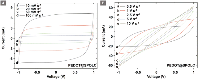
CV measurements of both composites show a quasi-rectangular shape when cycled using a symmetrical cell setup (Fig. S4, ESI†) between 1 and −1 V (Fig. 5A). At high scan rates, the shape turns into an ellipsoid as expected (Fig. 5B). This can be observed for the PEDOT@SPOLC and PEDOT@SPOLC/OLC (Fig. S5, ESI†) system.
The change in shape can be explained by kinetic limitations of the time sensitive electrochemical processes at the interface of OLC and conductive polymers. These incomplete processes result in a decreased stored charge.
Differences between both composites arise when the voltage window is increased. This investigation was possible due to the excellent electrochemical stability of PEDOT and the usage of an organic electrolyte (Fig. 6). A widening of the voltage range revealed a superior connection between CP and the carbon material for PEDOT@SPOLC (Fig. 6A and B) when compared with PEDOT@SPOLC/OLC (Fig. 6C and D).
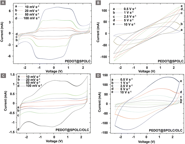 | ||
| Fig. 6 Comparison of cyclic voltammograms of PEDOT@SPOLC ((A): high, (B): low scan rates) and PEDOT@SPOLC/OLC ((C): high, (D): low scan rates). | ||
The CV curves for both composites show a characteristic shape for systems using PEDOT as pseudocapacitive active material.7 A drop in current starting at around 1 V indicates that the maximal pseudocapacitance is reached and PEDOT is completely doped. The subsequent decrease in current is more pronounced for PEDOT@SPOLC compared to PEDOT@SPOLC/OLC. The slower pseudocapacitive processes for PEDOT@SPOLC/OLC, expressed in flattened slopes in the cyclic voltammogram, support the finding of a more disadvantageous distribution and connection of PEDOT and carbon particles.
Faster pseudocapacitive processes for PEDOT@SPOLC (Fig. 6A) indicate a superior electrochemical interaction between PEDOT and OLC in the composite based on a functionalized template. As ten overlapping cycles are presented for each scan rate (Fig. 6), the excellent reversibility of the system is shown. Especially the redoping of PEDOT works without problems even after the electrodes were repolarized and reduced to −2.5 V.
These experiments support the idea of an electrical mediation between PEDOT and OLC in the presence of benzenesulfonic acid groups. To show this trend over a wide range of scan rates, the specific capacitance of the composites was compared for both potential ranges (Fig. 7).
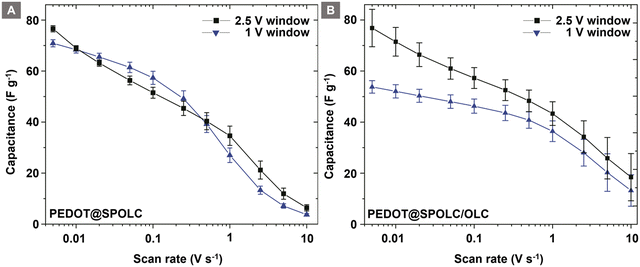 | ||
| Fig. 7 Comparison of the specific capacitance for potential windows of 1 V and 2.5 V for PEDOT@SPOLC (A) and PEDOT@SPOLC/OLC (B). | ||
For PEDOT@SPOLC, a specific capacitance of 77 F g−1 has been observed at a scan rate of 5 mV s−1 and an operating potential window of 2.5 V. Roughly the same capacitance (76 F g−1) was obtained in a 1 V potential window. Increasing the scan rate did not influence the difference of specific capacitance for both potential windows. In this context, PEDOT@SPOLC shows an independence of the selected voltage windows regarding its specific capacitance. In contrast, for the system in which sulfonated and pristine OLC were mixed (PEDOT@SPOLC/OLC), the specific capacitance is influenced by the voltage window (Fig. 7A). Especially at low scan rates, where time sensitive processes determine the capacitance, a certain potential is required to exhaust pseudocapacitive charge storage. This potential is provided by a large voltage window of 2.5 V (Fig. 7B).
This phenomenon underlines the importance of the morphology of the system. Superior performance can be observed for the specifically incorporated PEDOT compared to the partially functionalized system, especially at low scan rates where capacitance is dominated by pseudocapacitive processes.
With an increasing scan rate, the specific capacitance decreases for both systems. PEDOT@SPOLC/OLC maintains 19 F g−1 of its specific capacitance, whereas PEDOT@SPOLC retains only 6 F g−1 at a scan rate of 10 V s−1. The difference in specific capacitance regarding the two voltage windows fades for both composites at high scan rates, indicating a rise in influence of the non-faradaic processes over the slower faradaic pseudocapacitive processes.
At high scan rates, PEDOT@SPOLC/OLC delivers higher specific capacitance since less open porosity is blocked by PEDOT offering higher accessible surface to form an electrical double layer to store energy. Regarding the design of the composites, a different level of surface covering seems to offer the possibility for tuning the balance between faradaic and non-faradaic capacitance.
When compared to related materials, the maximal capacitance of PEDOT@SPOLC (77 F g−1 at 5 mV s−1) significantly exceeds the capacitance of pure PEDOT:PSS electrodes (29 F g−1 at 5 mV s−1)20 and supercapacitors based on pure OLC (up to 52 F g−1).21 Supercapacitors relying on organic solvents and nanofibrillar, structured PEDOT electrodes (70 F g−1 at 2 mV s−1)24 or reduced graphene oxide combined with PEDOT:PSS (81 F g−1 at 5 mV s−1) offer specific capacitances in the same range. For other PEDOT carbon composites, especially those using solvents with small diameters like aqueous electrolytes, values over 180 F g−1 have been reported (see Table S2 for additional values, ESI†).5,25 However, water only allows a much narrower voltage window and therefore limits the power density for the supercapacitor. For the combination of OLC and PEDOT:PSS, a comparable specific capacitance of 75 F g−1 was reported,9 but could not be maintained in long-term measurements (see below).
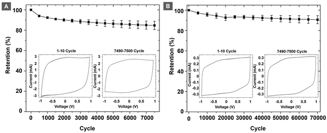
Cyclability and capacitance retention are important metrics to evaluate the performance of a supercapacitor. To evaluate the capacitance retention, electrodes of PEDOT@SPOLC were chosen over PEDOT@SPOLC/OLC on the basis of their superior electrochemical connection between carbon material and PEDOT. The electrodes were cycled 70![[thin space (1/6-em)]](https://www.rsc.org/images/entities/char_2009.gif) 000 times with a fast scan rate of 2.5 V s−1. Between segments, ten cycles at 5 mV s−1 were performed to increase the visibility of any impacts on pseudocapacitive processes (Fig. 8A). After this first test, a second series with a slow scan rate of 20 mV s−1, focusing mainly on the pseudocapacitance, was performed for 7500 cycles (Fig. 8B).
000 times with a fast scan rate of 2.5 V s−1. Between segments, ten cycles at 5 mV s−1 were performed to increase the visibility of any impacts on pseudocapacitive processes (Fig. 8A). After this first test, a second series with a slow scan rate of 20 mV s−1, focusing mainly on the pseudocapacitance, was performed for 7500 cycles (Fig. 8B).
For the fast cycling, 91% of the capacitance was retained after 70![[thin space (1/6-em)]](https://www.rsc.org/images/entities/char_2009.gif) 000 cycles while 85% of the initial capacitance was reached after 7500 cycles with a scan rate of 20 mV s−1. The major factor for damage and degrading capacitance in PEDOT:PSS systems are swelling induced cracks26 promoted by the pseudocapacitive current prominent at slow scan rates. SPOLC templates enable swelling of PEDOT into the open porous structure, reducing stress which subsequently suppresses the formation of cracks. At fast scan rates, mostly non-faradaic processes take place, which are less demanding for the integrity of the composite. In order to further assess the performance of the polymer composite, we have performed discharge capacitance measurements of the different composites (see Fig. S6 in the ESI†), which further confirm the suitability of the PEDOT@SPOLC system. In total, the system could retain a high share of its initial capacitance, proving an excellent stability of the composite in both tests. High retention was also reported for other composites where PEDOT was combined with carbon nanotubes (10
000 cycles while 85% of the initial capacitance was reached after 7500 cycles with a scan rate of 20 mV s−1. The major factor for damage and degrading capacitance in PEDOT:PSS systems are swelling induced cracks26 promoted by the pseudocapacitive current prominent at slow scan rates. SPOLC templates enable swelling of PEDOT into the open porous structure, reducing stress which subsequently suppresses the formation of cracks. At fast scan rates, mostly non-faradaic processes take place, which are less demanding for the integrity of the composite. In order to further assess the performance of the polymer composite, we have performed discharge capacitance measurements of the different composites (see Fig. S6 in the ESI†), which further confirm the suitability of the PEDOT@SPOLC system. In total, the system could retain a high share of its initial capacitance, proving an excellent stability of the composite in both tests. High retention was also reported for other composites where PEDOT was combined with carbon nanotubes (10![[thin space (1/6-em)]](https://www.rsc.org/images/entities/char_2009.gif) 000 cycles at 80 mV s−1, retention 95–98%)8 or with graphene (2000 cycles, retention 82%)6 underlining the suitability of carbon:PEDOT composites. However, depending on the manufacturing method, the degradation of the initial capacitance of these composites can be substantial, i.e. the combination of OLC and PEDOT:PSS showed a loss of 19% of its initial capacitance already after 300 cycles.27
000 cycles at 80 mV s−1, retention 95–98%)8 or with graphene (2000 cycles, retention 82%)6 underlining the suitability of carbon:PEDOT composites. However, depending on the manufacturing method, the degradation of the initial capacitance of these composites can be substantial, i.e. the combination of OLC and PEDOT:PSS showed a loss of 19% of its initial capacitance already after 300 cycles.27
This is where our approach based on the template assisted ionic attraction of PEDOT onto functionalized OLC improves the capacitance retention of the device significantly. It combines a wide potential window and long-term stability. These results reflect the importance of the morphology of PEDOT in the presence of carbon particles. Besides, benzenesulfonic acid groups emerged as a vital component to dispersing carbon in aqueous media and to attracting and integrating PEDOT into the composite.
Conclusion
Sulfonated onion-like carbon (SPOLC) was used as a template for electrostatically guided in situ polymerization of 3,4-ethylenedioxythiophene (EDOT) to form an active material for supercapacitor electrodes. The composite material combines the pseudocapacitive and binding capabilities of PEDOT with the mechanical stability of OLC while overcoming the problem of indispersible starting materials. Key element to reach a stable dispersion was the covalent functionalization of OLC with benzenesulfonic acid groups whose anionic charge also attracts and locks PEDOT tightly at the surface of the modified OLC (SPOLC) particles. While the PEDOT deposition was proven by Raman and TGA data for all composites, differences in morphology of PEDOT and OLC have been revealed by HRTEM. Electrochemical characterization of the composite showed a maximal capacitance of 77 F g−1 at a scan rate of 5 mV s−1. A superior electrical connection of the functionalized composite was concluded as a result of the performance in cyclic voltammetry measurements. In long term stability tests with over 70![[thin space (1/6-em)]](https://www.rsc.org/images/entities/char_2009.gif) 000 cycles, 91% of the initial capacitance could be retained, demonstrating the mechanical stability of the connection between PEDOT and SPOLC.
000 cycles, 91% of the initial capacitance could be retained, demonstrating the mechanical stability of the connection between PEDOT and SPOLC.
In perspective, PEDOT@SPOLC could be also used as additive for sodium ion cathodes, where PEDOT adopts the role of the binder and OLC serves as a spherical conductive additive whose structural integrity prevents trapping of sodium ions currently posing a problem for many commercial conductive additives.28
Conflicts of interest
There are no conflicts of interest to declare.Acknowledgements
The financial support of this project by the Bavarian State Ministry of the Environment and Consumer Protection is gratefully acknowledged (TNT01NaT-72356). We thank the Fraunhofer Institute for Silicate Research for access to the potentio-/galvanostat (VMP300 Bio-Logic) and Lukas Gold for the introduction to the operation of the setup. We acknowledge Martin Kamp for the measurement of the transmission electron micrographs and Stephan Kirchmayer for discussions concerning the properties of PEDOT.References
- H.-W. Chen and C. Li, Chin. J. Polym. Sci., 2020, 38(5), 435–448, DOI:10.1007/s10118-020-2373-2.
- R. A. Fisher, M. R. Watt and W. J. Ready, ECS J. Solid. State Sci. Technol., 2013, 2(10), M3170, DOI:10.1149/2.017310jss.
- G. J. Adekoya, R. E. Sadiku and S. S. Ray, Macromol. Mater. Eng., 2021, 306(3), 2000716, DOI:10.1002/mame.202000716.
- M. Boota and Y. Gogotsi, Adv. Energy Mater., 2019, 9(7), 1802917, DOI:10.1002/aenm.201802917.
- F. Niu, R. Guo, L. Dang, J. Sun, Q. Li, X. He, Z. Liu, Z. Lei and A. C. S. Appl, Energy Mater., 2020, 3(8), 7794–7803, DOI:10.1021/acsaem.0c01202.
- M. A. A. M. Abdah, N. A. Zubair, N. H. N. Azman and Y. Sulaiman, Mater. Chem. Phys., 2017, 192, 161–169, DOI:10.1016/j.matchemphys.2017.01.058.
- D. Wang, C. Lu, J. Zhao, S. Han, M. Wu and W. Chen, RSC Adv., 2017, 7(50), 31264–31271, 10.1039/c7ra05469f.
- H. Zhou and X. Zhi, Synth. Met., 2017, 234, 139–144, DOI:10.1016/j.synthmet.2017.10.011.
- (a) G. Siemiaszko, J. Breczko, A. Hryniewicka, A. Ilnicka, K. H. Markiewicz, A. P. Terzyk and M. E. Plonska-Brzezinska, Sci. Rep., 2023, 13, 6606, DOI:10.1038/s41598-023-33874-w; (b) M. E. Plonska-Brzezinska, M. Lewandowski, M. Blaszyk, A. Molina-Ontoria, T. Lucinski and L. Echegoyen, Chem. Phys. Chem., 2012, 13(18), 4134–4141, DOI:10.1002/cphc.201200789.
- C. Portet, G. Yushin and Y. Gogotsi, Carbon, 2007, 45(13), 2511–2518, DOI:10.1016/j.carbon.2007.08.024.
- A. Palkar, F. Melin, C. M. Cardona, B. Elliott, A. K. Naskar, D. D. Edie, A. Kumbhar and L. Echegoyen, Chem. – Asian J., 2007, 2(5), 625–633, DOI:10.1002/asia.200600426.
- J. D. Velásquez, M. Tomczykowa, M. E. Plonska-Brzezinska and M. N. Chaur, Mater., 2020, 13(5), 1141, DOI:10.3390/ma13051141.
- K. Bogdanov, A. Fedorov, V. Osipov, T. Enoki, K. Takai, T. Hayashi, V. Ermakov, S. Moshkalev and A. Baranov, Carbon, 2014, 73, 78–86, DOI:10.1016/j.carbon.2014.02.041.
- A. V. Volkov, K. Wijeratne, E. Mitraka, U. Ail, D. Zhao, K. Tybrandt, J. W. Andreasen, M. Berggren, X. Crispin and I. V. Zozoulenko, Adv. Funct. Mater., 2017, 27(28), 1700329, DOI:10.1002/adfm.201700329.
- P. Sakunpongpitiporn, K. Phasuksom, N. Paradee and A. Sirivat, RSC Adv., 2019, 9(11), 6363–6378, 10.1039/c8ra08801b.
- X. Liu, J. Zai, A. Iqbal, M. Chen, N. Ali, R. Qi and X. Qian, J. Colloid Interface Sci., 2020, 565, 270–277, DOI:10.1016/j.jcis.2020.01.028.
- B. Friedel, P. E. Keivanidis, T. J. Brenner, A. Abrusci, C. R. McNeill, R. H. Friend and N. C. Greenham, Macromolecules, 2009, 42(17), 6741–6747, DOI:10.1021/ma901182u.
- J. A. Luceño Sánchez, R. Peña Capilla and A. M. Díez-Pascual, Polymers, 2018, 10(10), 1169, DOI:10.3390/polym10101169.
- Y. Xu, Y. Wang, J. Liang, Y. Huang, Y. Ma, X. Wan and Y. Chen, Nano Res., 2009, 2(4), 343–348, DOI:10.1007/s12274-009-9032-9.
- Y. Liu, B. Weng, J. M. Razal, Q. Xu, C. Zhao, Y. Hou, S. Seyedin, R. Jalili, G. G. Wallace and J. Chen, Sci. Rep., 2015, 5, 17045, DOI:10.1038/srep17045.
- M. Zeiger, N. Jaeckel, V. N. Mochalin and V. Presser, J. Mater. Chem. A, 2016, 4(9), 3172–3196, 10.1039/C5TA08295A.
- V. Dhand, M. Yadav, S. H. Kim and K. Y. Rhee, Carbon, 2021, 175, 534–575, DOI:10.1016/j.carbon.2020.12.083.
- (a) M. Zeiger, N. Jaeckel, D. Weingarth and V. Presser, Carbon, 2015, 94, 507–517, DOI:10.1016/j.carbon.2015.07.028;; (b) C. Bauer, A. Bilican, S. Braxmeier, G. Reichenauer and A. Krueger, Carbon, 2022, 197, 555, DOI:10.1016/j.carbon.2022.06.041.
- J. M. D’Arcy, M. F. El-Kady, P. P. Khine, L. Zhang, S. H. Lee, N. R. Davis, D. S. Liu, M. T. Yeung, S. Y. Kim and C. L. Turner, ACS Nano, 2014, 8(2), 1500–1510, DOI:10.1021/nn405595r.
- M. Rajesh, C. J. Raj, R. Manikandan, B. C. Kim, S. Y. Park and K. H. Yu, Mater. Today Energy, 2017, 6, 96–104, DOI:10.1016/j.mtener.2017.09.003.
- (a) M. Modarresi, A. Mehandzhiyski, M. Fahlman, K. Tybrandt and I. Zozoulenko, Macromolecules, 2020, 53(15), 6267–6278, DOI:10.1021/acs.macromol.0c00877; (b) E. Pameté, L. Köps, F. A. Kreth, S. Pohlmann, A. Varzi, T. Brousse, A. Balducci and V. Presser, Adv. Energ. Mater., 2023, 13, 2301008, DOI:10.1002/aenm.202301008.
- M. Plonska-Brzezinska, M. Lewandowski, M. Błaszyk, A. Molina-Ontoria, T. Luciński and L. Echegoyen, Chem. Phys. Chem., 2012, 13(18), 4134–4141, DOI:10.1002/cphc.201200789.
- K. Pfeifer, S. Arnold, Ö. Budak, X. Luo, V. Presser, H. Ehrenberg and S. Dsoke, J. Mater. Chem. A, 2020, 8(12), 6092–6104, 10.1039/d0ta00254b.
Footnote |
| † Electronic supplementary information (ESI) available: Detailed synthetic procedures, additional Raman spectra, EDX measurements, pictures of the electrodes as well as a schematic overview of the cell setup and additional CV measurements. See DOI: https://doi.org/10.1039/d4ya00048j |
| This journal is © The Royal Society of Chemistry 2024 |


