
 Open Access Article
 This Open Access Article is licensed under a Creative Commons Attribution-Non Commercial 3.0 Unported Licence
Precise patterning of gold nanoparticle gratings on gelatin films†
Álex
Farrando-Pérez
 a,
José M.
Villalvilla
a,
Víctor
Bonal‡
a,
Pedro G.
Boj
b,
José A.
Quintana
b and
María A.
Díaz-García
*a
a,
José M.
Villalvilla
a,
Víctor
Bonal‡
a,
Pedro G.
Boj
b,
José A.
Quintana
b and
María A.
Díaz-García
*a
aDepartamento de Física Aplicada and Instituto Universitario de Materiales de Alicante, Universidad de Alicante, Alicante, 03080, Spain. E-mail: maria.diaz@ua.es
bDepartamento de Óptica, Farmacología y Anatomía and Instituto Universitario de Materiales de Alicante, Universidad de Alicante, Alicante, 03080, Spain
First published on 15th July 2024
Abstract
A method to fabricate gold nanoparticles in gelatin films and pattern them into gratings with periods down to 200 nm is reported. The procedure, based on holographic lithography, dry etching and temperature annealing, enables tuning the size and particle distribution. These materials offer potential for wearable and bio-compatible plasmonic-based applications.
In the last decades, many efforts have been devoted to the preparation of gold nanoparticles (AuNPs), motivated by their potential applications in different scientific areas.1 Particularly, there has been plenty of work towards the preparation of composite materials incorporating AuNPs, towards the exploitation of their plasmonic properties in biosensing applications,2 surface-enhanced Raman spectroscopy (SERS),3 medical treatments,4etc. For such purposes, the use of plasmonic materials prepared as NPs is interesting because their properties can benefit of the existence of localized surface plasmon resonances (LSPR), which constitute suitable platforms for low concentration small bio-target sensing.3 Moreover, the plasmonic NPs can be spatially organized across the sample conforming gratings (NPGs) or arrays, providing a significant improvement in sensor sensitivity, thanks to the coupling between the LSPR and the grating modes.5
Among many metals displaying plasmonic properties, gold is by far the most widely investigated because of its excellent biocompatibility and low toxicity, being these features crucial for biomedical applications.6 Commonly, AuNPs are chemically synthesized in organic solvents, involving the reduction of metal salts to gold atoms with the help of reducing agents. Generally, the solvents and chemicals used are environmentally unfriendly. Thus, many efforts have been devoted towards developing green-chemical methods based on non-toxic and biocompatible agents, such as polyhydroxylated biomolecules.7 Additionally, these agents provide protection to the synthesized NPs, thus improving their biocompatibility and potential for food and biological applications. In this context, gelatin (a food-grade biopolymer) has shown good reduction and stabilization capabilities for the synthesis of AuNPs.7b,c Moreover, gelatin has been used as the cladding layer in shell-isolated plasmonic NPs, designed to enhance the plasmonic signals in SERS spectroscopy.8
For the purpose of hosting plasmonic NPs, there are additional advantages of using a polymer (such as gelatin): it can be easily processed from inexpensive solution-based methods (such as spin coating, printing, etc.), it has low weight, high transparency and is suitable for a wide range of simple nanofabrication procedures, such as nanoimprint lithography (NIL), direct laser patterning or holographic lithography (HL). All these properties are essential for the development of wearable applications, which are growing significantly in recent years.9
With regards to methods to fabricate plasmonic NPGs, most reported studies (mainly targeting LSPR sensor applications), have implied the use of sophisticated techniques (i.e. electron-beam lithography) to fabricate gratings over inorganic substrates, aiming for a very precise control of the particles and their spatial distribution.3,5 Some studies have focused on using polymeric substrates towards the exploitation of other advantages (biocompatibility, low weight, mechanical flexibility, etc.).10 For example, laser ablation of a gold film on a polymeric substrate,10a,b photo-reduction followed by an annealing of gold precursors in a polyvinyl alcohol film,10c or simply the annealing of these precursors in a SU-8 resist,10d colloidal gold nanoparticles deposition in the grooves of photo-resist grating structures,10e or more sophisticated methods such as the use of photovoltaic tweezers.10f An attractive technique for such purposes is HL, because it allows the preparation of large samples and offers a great versatility on the control of the geometrical parameters of the resulting grating.11 Despite some reports of plasmonic NPGs (with grating periods in the range 0.5 to 10 μm) assisted by HL, they have a limited control on the geometrical grating parameters.10c Moreover, their implementation in real applications remains as a challenge. Thus, finding methods to prepare plasmonic NPs in polymeric materials and to organize them into gratings, having a fine control over the particle size and distribution is of great interest.
In the present work we report a method to prepare gold nanoparticle gratings (AuNPGs) on gelatin films. Remarkably, the method easily allows grating patterning with a much higher resolution (periods down to 200 nm) than other reported procedures.10c It is inspired on a procedure reported by the authors for making surface-relief gratings on dichromated gelatin (DCG) layers, to serve as distributed feedback (DFB) resonators for lasers.11 For such applications, the DCG gratings were fabricated by HL and subsequent dry-development in an oxygen plasma. The optimization of the gelatin films for food industry applications through different plasma treatments has also been targeted.12
The method reported here for AuNPG fabrication starts with the deposition of a DCG film (thickness = 120 nm) over a transparent fused silica substrate. This is accomplished by spin coating a hot water solution (at 40 °C) containing natural inert gelatin and ammonium dichromate. More details can be found elsewhere.11c The AuNPG is then fabricated with a procedure consisting of several steps, as graphically illustrated in Fig. 1 and briefly described as follows (more details in ESI†). The first step consists of the holographic exposure of the DCG layer followed by a desensitization (elimination of ammonium dichromate through a water washing and rapid drying), so the film becomes no longer sensitive to UV light (Fig. 1a and b). This is like the first step for DCG laser resonator fabrication. After that, the procedure is different because here, the layer is doped with a gold precursor (HAuCl4), see Fig. 1c. Thus, the subsequent application of an oxygen plasma (Fig. 1d), which contains reactive oxygen species (ROS), leads not only to the creation of a relief grating (as in the DCG resonator fabrication), but also to the production of electrons which enable the reduction of the Au3+ ions into gold atoms, according to the following reaction:
| Au3+ + 3e− → Au0 | (1) |
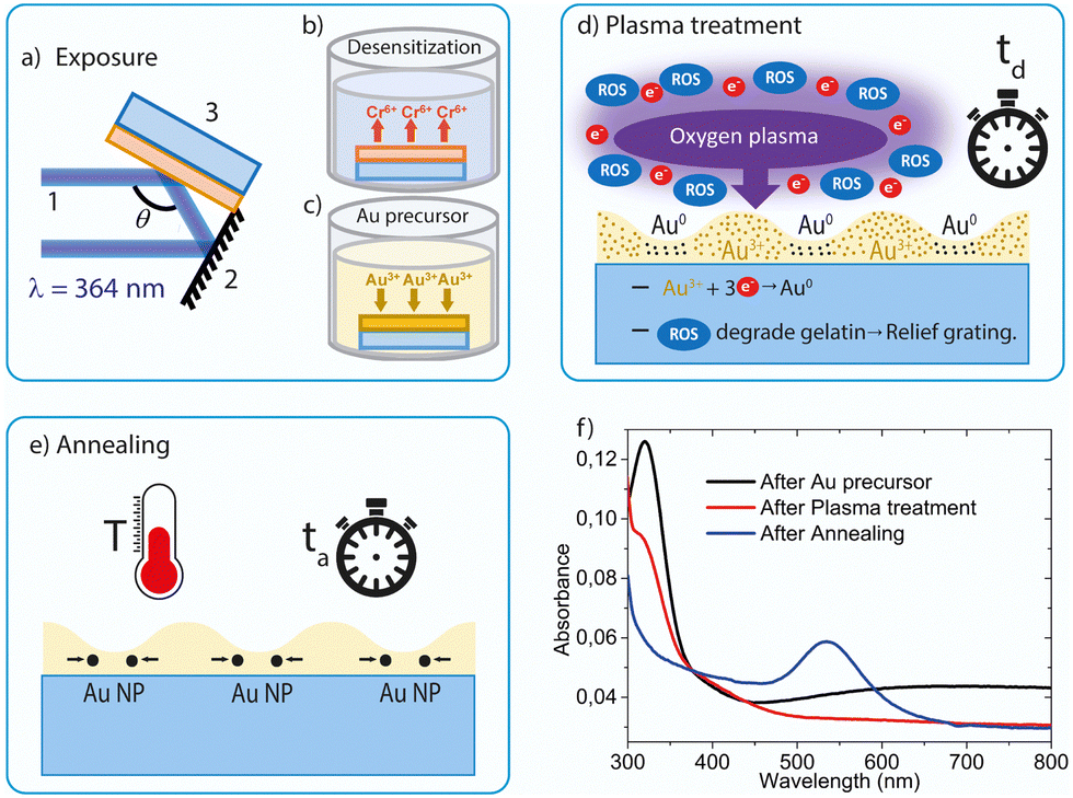 | ||
| Fig. 1 Fabrication procedure of a gold nanoparticle grating (AuNPG) on a dichromated gelatin (DCG) film. Steps for AuNPG fabrication: (a) holographic exposure; (b) desensitization; (c) doping with gold precursor; (d) oxygen plasma treatment (dry development) for a given time (td); (e) annealing at a given temperature (T) for a certain time (ta); (f) absorption spectra recorded after different fabrication steps for a sample exposed to an interference fringe pattern of period 200 nm, precursor concentration of 2 × 10⁻² M, td = 6 min, T = 180 °C, ta = 20 min. | ||
Absorption spectroscopy was used to determine proper times and temperatures for the plasma and annealing treatments, and more generally to understand the mechanisms responsible for the grating formation. This technique allows monitoring the presence of gold precursors (Au3+ ions) and AuNPs, after each step of the process (see example in Fig. 1f). Au3+ ions are identified by a peak in the absorption spectrum at around 325 nm, while the observation of the gold plasmon resonance in the range of 500–550 nm is indicative of the presence of gold nanoparticles.14 The peak observed in Fig. 1f at 325 nm, related to the Au3+ ions, is seen after the doping step (c). Then, after the plasma treatment (step d), its intensity weakens and gets drastically reduced after the annealing. On the other hand, the absorption at 500–550 nm range, associated to the plasmon, is not observed right after the plasma treatment, indicating that no appreciable amounts of AuNPs are formed at this stage in the process. Absorption in this region appears after some time under a given annealing T, growing until saturation. The time to reach this state depends on the applied T and is the one selected for the annealing treatment (ta = 20 min and T = 180 °C for the case shown in Fig. 1f). At this stage, at which the plasmonic band is present, the color sample turns purple. It should be noted that the absorbance observed at long wavelengths in the film spectrum, only prior to the relief grating formation, is due to an effect not related to the phenomena of interest in this work. Particularly, it corresponds to the interference between the directly transmitted light and that transmitted after two internal reflections in the film, which can be used to directly determine the thickness of the DCG film.15
Importantly, through backscattered field emission scanning electron (BS-FESEM) microscopy, it is shown that the AuNPG characteristics can be finely tuned by proper adjustment of some fabrication parameters: the gold precursor concentration, the plasma treatment time, td, and the annealing temperature, T, and time, ta. The presence of AuNPs is identified in the BS-FESEM images through the observation of bright circles, which can be seen even when the particles are in the deeper regions of the films. Besides, the average size, the total number of particles, Np, and their spatial distribution across the sample can be determined from histograms obtained with these figures.16a Additionally, the circularity of the particles can be quantified through the parameter c, defined as c = 4πA/p2, where A is the area of the nanoparticle and p its perimeter. For a perfectly circular particle, c = 1, while c would tend to 0 as the shape differs from a circle.16b The crystallinity of the particles was explored through X-ray diffraction (XRD) analysis (see Fig. S1, ESI†). Although results suggest a crystalline structure, the signal was too weak to extract reliable information. Moreover, other images, using the lower energy detector for secondary electrons (SE-FESEM), as well as transmission electron microscopy (TEM) aided to confirm some aspects of the method and the AuNPGs profile.
We first examined the effect on the AuNPGs characteristics of the gold precursor concentration used in step c of the fabrication procedure. AuNPGs with relatively good contrast could be prepared with precursor concentrations between 5 × 10⁻³ M and 2 × 10⁻² M (the range explored was 1 × 10⁻⁴ – 5 × 10⁻² M). For low concentrations, the density of formed particles was low, while with high concentrations, NPs were found everywhere, even for short td values. Thus, for the rest of studies we used a concentration of 2 × 10⁻² M.
The effect on the AuNPGs characteristics of varying the parameters of the plasma and the annealing treatments, are analyzed through the BS-FESEM images shown in Fig. 2a–d (all correspond to samples with a period of 200 nm). The effect of the plasma treatment time, td, can be analyzed through the images shown in Fig. 2a and b, obtained with different td values (3 and 6 min, respectively) and the same annealing treatment (T = 120 °C, ta = 8 h). It is found that td has an important effect on the duty-cycle of the grating (defined as the ratio between the AuNPG width and the DCG grating period), whose value increases from about 0.5 to 0.7, when td increases from 3 to 6 min. We also observed (data not shown) that for td = 9 min, the duty cycle kept increasing, reaching a value close to unity. This effect can be explained considering that the formation of the AuNPs depends on the hardness of the DCG. In the unexposed areas, the DCG is much softer than in the exposed ones, facilitating the production of gold according to eqn (1). Besides, note that in the exposed areas, the hardness varies locally because of the sinusoidal light intensity distribution in the exposure step, Fig. 1a (it is maximal in the peak distribution peak and softer in the tails). According to this idea, observing an increase in the surface area occupied by the AuNPs, upon the increase of td, looks reasonable. On the other hand, the effect of the annealing conditions (temperature, T; and time, ta) on the duty cycle seem to be negligible according to results shown in Fig. 2c and d, which correspond to AuNPGs, both obtained with td = 6 min, but subjected to very different annealing conditions: T = 20 °C (room temperature), for a ta = 1 month (Fig. 2c); and annealing at T = 180 °C, for a ta = 20 min (Fig. 2d). In both cases, a similar duty-cycle is observed (approximately 0.7), which corresponds also to the value obtained for T = 120 °C (Fig. 2b). To get further insights on the mechanisms leading to the formation of AuNPs and AuNPGs, we performed spectrophotometric analysis (like those of Fig. 1f) for the samples related to Fig. 2. The plasmon peak observed in the absorption spectra, as a signature of the presence of AuNPs, is similar for samples subjected to the treatments of Fig. 2b and c (T = 120 °C, ta = 8 h; and T = 20 °C and ta = 1 month, respectively). This means that the AuNPs can be formed at any temperature, whenever ta is sufficiently long. However, note that the number and size of the nanoparticles depend significantly on the magnitude of the treatments (see histograms shown in the insets of Fig. 2). Indeed, the number of particles increases upon the increase of td (see histograms of Fig. 2a and b) and the increase of T (see histograms of Fig. 2b–d). The particle size also increases with td, as well as the size distribution: from 10–20 nm (td = 3 min) to around 5–35 nm (td = 6 min). With regards to the effect of the annealing treatment, it does not seem to influence the range of sizes of the particles formed (see histograms in Fig. 2b–d). On the other hand, when T is very high (Fig. 2d), most of the particles are small (10–20 nm). It should also be remarked that the magnitude of the treatments influences the spatial distribution of the particles across the sample (see histograms in Fig. S2 ESI†). Particles get majorly distributed conforming a grating, particularly in the regions close to the valleys of the gratings, when mild treatments are used, that is, for short td (3 min) and moderate T (120 °C), as in Fig. 2a. On the other hand, for larger td (6 min) and T (180 °C), as in Fig. 2b and d, respectively, the particles are seen in other regions. Note that when no annealing is applied (Fig. 2c) particles are also conforming a grating, but the time to get that is rather long (1 month). The fact that the AuNPs are formed in the DCG regions attacked by the plasma treatment, that is the relief grating valleys (non-exposed to light, or exposed with a very low intensity, in step a), is confirmed by the image shown in Fig. 2e, which corresponds to a FESEM image recorded using the secondary and backscatter electron detectors simultaneously, particularly for the grating related to Fig. 2a. These results are further confirmed by TEM (see Fig. 2f). The increase of the width of the regions with AuNPs (increase of the duty cycle) as td increases, is clearly seen.
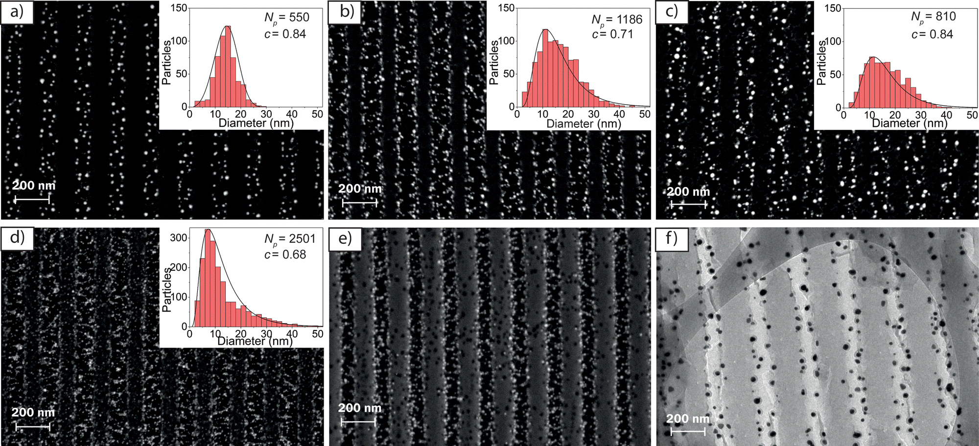 | ||
| Fig. 2 Microscopy images for AuNPGs (200 nm grating period, 2 × 10⁻² M gold precursor concentration) prepared under different plasma and annealing treatment parameters. (a)–(d) are BS-FESEM images: (a) and (b) same annealing conditions (T = 120 °C, ta = 8 h), and different plasma treatment times, td (3 and 6 min, respectively); (c) and (d) same td = 6 min, and different annealing conditions: T = 20 °C and ta = 1 month (in c); and T = 180 °C and ta = 20 min (in d). Insets are histograms displaying the number of particles versus their diameter (Np: total number of particles; c: mean circularity) for sample shown in (a), it is included a FESEM image recorded by using the secondary and backscatter electron detectors simultaneously (e), and a TEM image (f). | ||
The shape of the particles is approximately spherical, with circularity values ranging from 0.84–0.68 depending on fabrication conditions (see insets in Fig. 2). The spherical shape is confirmed through the TEM image shown in Fig. 2f. Moreover, this morphology is confirmed when the gelatin support is removed. For such purpose, a AuNPG was calcinated in a muffle furnace at 800 °C for 1 hour. Through BS-SEM microscopy (Fig. S3a, ESI†) the vertical alignment is perceptible, even without the gelatin support. Although the particles have moved and spread almost over the entire surface, the spherical shape of the particles can be clearly seen. Besides, the image can be used to make a statistic of the NPs final size (see histogram in Fig. S3b, ESI†). The particle size ranges from 5 to 35 nm, and the average size is about 20 nm.
Finally, we explored the effect of changing the grating period to 400 nm (Fig. S4, ESI†). Like gratings with a period of 200 nm, the increase in the particle formation rate due to annealing, produces a larger number of particles, but of smaller size. Besides, some particles begin to appear on the highly exposed gelatin areas. The sinusoidal character of the formed gratings, with a depth of around 100 nm, was confirmed by SE-FESEM (Fig. S4c, ESI†).
In summary, we report a method, based on HL and treatments of oxygen plasma and annealing, to prepare AuNPGs in gelatin films which offer great promise for wearable and bio-compatible plasmonic-based applications. Particularly, they offer prospects for sensing if configured as DFB lasers with top-layer resonators,11d whose performance would be likely improved by plasmonic effects provided by the AuNPs. The procedure is environmentally friendly (based on green chemistry methods) and enables grating formation with periods as small as 200 nm, significantly lower than other HL-based reported methods.10c The use of HL as main grating fabrication tool, has advantages over other methods,10 because it enables the preparation of large samples (various centimeters) and a fine tuning of the particle size and distribution. Further developments are envisaged, such as the use of other supporting polymers, or additional optimizations through control of other parameters such as grating depth, grating profile or average exposure.
This work was supported by the “Ministerio de Ciencia e Innovación” (MCIN) of Spain and the European Regional Development Fund (grant no. PID2020-119124RB-I00). Besides, this study part of the Advanced Materials program supported by the Spanish MCIN with funding from European Union NextGenerationEU and by Generalitat Valenciana (grant no. MFA/2022/045).
Data availability
The data supporting the findings of this manuscript are available from the corresponding authors upon reasonable request.Conflicts of interest
There are no conflicts to declare.Notes and references
- (a) R. Elghanian, J. J. Storhoff, R. C. Mucic, R. L. Letsinger and C. A. Mirkin, Science, 1997, 277, 1078–1081 CrossRef CAS PubMed; (b) J. M. Wessels, H.-G. Nothofer, W. E. Ford, F. von Wrochem, F. Scholz, T. Vossmeyer, A. Schroedter, H. Weller and A. Yasuda, J. Am. Chem. Soc., 2004, 126, 3349–3356 CrossRef CAS.
- (a) H. Jung, J. Jung, Y. Kim, D. Kwon, B. G. Kim, H. Bin and H. Ho, BioChip J., 2018, 12, 249–256 CrossRef CAS; (b) X. Chen, D. Cui and L. Zhang, Micro Nano Lett., 2016, 11, 20–23 CrossRef CAS; (c) A. Kaushik, R. Kumar, S. K. Arya, M. Nair, B. D. Malhotra and S. Bhansali, Chem. Rev., 2015, 115, 4571–4606 CrossRef CAS.
- (a) J. N. Anker, W. P. Hall, O. Lyandres, N. C. Shah, J. Zhao and R. P. Van Duyne, Nat. Mater., 2008, 7, 442–453 CrossRef CAS; (b) K. A. Maleeva, I. E. Kaliya, A. P. Tkach, A. A. Babaev, M. A. Baranov, K. Berwick, T. S. Perova, A. V. Baranov and K. V. Bogdanov, Materials, 2022, 15, 5197 CrossRef CAS.
- J. F. Masson, ACS Sens., 2017, 2, 16–30 CrossRef CAS.
- A. K. Pandey and A. K. Sharma, IEEE Sens. J., 2021, 21, 12633–12644 CAS.
- (a) D. Pissuwan, T. Niidome and M. B. Cortie, J. Controlled Release, 2011, 149, 65–71 CrossRef CAS; (b) A. P. Subramanian, S. K. Jaganathan, A. Manikandan, K. N. Pandiaraj, N. Gomathi and E. Supriyanto, RSC Adv., 2016, 6, 48294–48314 RSC.
- (a) H. Huang and X. Yang, Biomacromolecules, 2004, 5, 2340–2346 CrossRef CAS; (b) J. J. Zhang, M.-M. Gu, T.-T. Zheng and J.-J. Zhu, Anal. Chem., 2009, 81, 6641–6648 CrossRef CAS PubMed; (c) L. Lu, K. Ai and Y. Ozaki, Langmuir, 2008, 24, 1058–1063 CrossRef CAS PubMed.
- C. Lee and P. Zhang, J. Raman Spectrosc., 2013, 44, 823–826 CrossRef CAS.
- (a) M. Nan, B. A. Darmawan, G. Go, S. Zheng, J. Lee, S. Kim, T. Lee, E. Choi, J.-O. Park and D. Bang, Biosensors, 2023, 13, 184 CrossRef CAS PubMed; (b) G. P. Singh and N. Sardana, Plasmonics, 2022, 17, 1869–1888 CrossRef PubMed.
- (a) C. Hung, W. H. Cheng, M. S. Tsai, W. C. Chung, I. M. Jiang and P. Yeh, Appl. Phys. Lett., 2008, 93, 061109 CrossRef; (b) T. Zhai, Y. Wang, H. Liu and X. Zhang, Opt. Express, 2015, 23, 1863 CrossRef CAS; (c) E. Nadal, N. Barros, H. Glénat, J. Laverdant, D. S. Schmool and H. Kachkachi, J. Mater. Chem. C, 2017, 5, 3553–3560 RSC; (d) Q. T. Pham, G. L. Ngo, X. A. Nguyen, C. T. Nguyen, I. Ledoux-Rak and N. D. Lai, Polymers, 2022, 15, 16 CrossRef PubMed; (e) Y. Wang and X. Zhang, Nanoscale, 2019, 11, 17807–17814 RSC; (f) I. Elvira, J. F. Muñoz-Martínez, M. Jubera, A. García-Cabañes, J. L. Bella, P. Haro-González, M. A. Díaz-García, F. Agulló-López and M. Carrascosa, Adv. Mater. Technol., 2017, 2, 1700024 CrossRef.
- (a) J. A. Quintana, J. M. Villalvilla, M. Morales-Vidal, P. G. Boj, X. Zhu, N. Ruangsupapichat, H. Tsuji, E. Nakamura and M. A. Díaz-García, Adv. Opt. Mater., 2017, 5, 1700238 CrossRef; (b) V. Bonal, J. M. Villalvilla, J. A. Quintana, P. G. Boj, N. Lin, S. Watanabe, K. Kazlauskas, O. Adomeniene, S. Jursenas, H. Tsuji, E. Nakamura and M. A. Díaz-García, Adv. Opt. Mater., 2020, 8, 2001153 CrossRef CAS; (c) V. Bonal, J. A. Quintana, J. M. Villalvilla, P. G. Boj, R. Muñoz-Mármol, J. C. Mira-Martínez and M. A. Díaz-García, Polymers, 2021, 13, 3843 CrossRef CAS; (d) Á. Farrando-Pérez, J. M. Villalvilla, J. A. Quintana, P. G. Boj and M. A. Díaz-García, Adv. Opt. Mater., 2024 Search PubMed , under revisions.
- (a) A. Vesel, Mater. Technol., 2012, 46, 7–12 CAS; (b) J. Bassaganya-Riera, E. M. Berry, E. E. Blaak, B. Burlingame, J. le Coutre, W. van Eden, A. El-Sohemy, J. B. German, D. Knorr, C. Lacroix, M. Muscaritoli, D. C. Nieman, M. Rychlik, A. Scholey and M. Serafini, Front. Nutr., 2021, 7, 606378 CrossRef PubMed.
- V. Lotito and T. Zambelli, Adv. Colloid Interface Sci., 2022, 299, 102538 CrossRef CAS.
- E. Nadal, N. Barros, L. Peres, V. Goetz, M. Respaud, K. Soulantica and H. Kachachi, React. Chem. Eng., 2020, 5, 330–341 RSC.
- (a) V. Bonal, J. A. Quintana, R. Muñoz-Mármol, J. M. Villalvilla, P. G. Boj and M. A. Díaz-García, Thin Solid Films, 2019, 692, 137580 CrossRef CAS; (b) V. Bonal, J. A. Quintana, J. M. Villalvilla, R. Muñoz-Mármol, J. C. Mira-Martínez, P. G. Boj, M. E. Cruz, Y. Castro and M. A. Díaz-García, Polymers, 2021, 13, 2545 CrossRef CAS PubMed.
- (a) J. Schindelin, I. Arganda-Carreras, E. Frise, V. Kaynig, M. Longair, T. Pietzsch, S. Preibisch, C. Rueden, S. Saalfeld, B. Schmid, J. Y. Tinevez, D. James White, V. Hartenstein, K. Eliceiri, P. Tomancak and A. Cardona, Nat. Methods, 2012, 9, 676–682 CrossRef CAS; (b) V. Lotito and T. Zambelli, Adv. Colloid Interface Sci., 2020, 284, 102252 CrossRef CAS.
Footnotes |
| † Electronic supplementary information (ESI) available. See DOI: https://doi.org/10.1039/d4tc01970a |
| ‡ Present address: Departamento de Física Aplicada, Universidad Autónoma de Madrid, C/Tomás y Valiente 7, 28049, Madrid, Spain. |
| This journal is © The Royal Society of Chemistry 2024 |