
 Open Access Article
 This Open Access Article is licensed under a Creative Commons Attribution-Non Commercial 3.0 Unported Licence
Simple fabrication of laser-induced graphene functionalized with a copper-based metal–organic framework and its application in solid-state supercapacitors†
Samuel
Morales-Cámara
a,
Victor
Toral
b,
Iñigo J.
Vitorica-Yrezabal
 a,
Almudena
Rivadeneyra
b,
Luis
Pereira
cd,
Sara
Rojas
a and
Francisco J.
Romero
*b
a,
Almudena
Rivadeneyra
b,
Luis
Pereira
cd,
Sara
Rojas
a and
Francisco J.
Romero
*b
aDepartment of Inorganic Chemistry, University of Granada, Av. De Fuente Nueva, 18071, Granada, Spain
bDepartment of Electronics and Computer Technology, University of Granada, Av. De Fuente Nueva, 18071, Granada, Spain. E-mail: franromero@ugr.es
cAlmaScience Colab, 2829-516 Caparica, Portugal
dCENIMAT/i3N, Department of Materials Science, School of Science and Technology, NOVA University Lisbon and CEMOP/UNINOV, 2829-516 Caparica, Portugal
First published on 2nd May 2024
Abstract
Flexible thin-film electronics based on functionalized laser-induced graphene (LIG) hold great promise for a diverse range of applications, including biosensors and energy storage devices. In this study, we present a simple and direct method for synthesizing LIG functionalized with a copper-based metal–organic framework (MOF). The proposed synthesis procedure involves a one-step laser photothermal process on the surface of a carbon-rich polyimide to obtain LIG, followed by a simple layer-by-layer technique for growing Cu-BTC crystals within the porous structure of LIG. Structural characterization through various techniques confirms the successful deposition of crystalline Cu-BTC within the electrically conductive LIG surface. Cu-BTC@LIG composites are highly valuable candidate materials for multiple applications. In particular, we demonstrate the use of Cu-BTC@LIG as an electrode for electrochemical supercapacitors, increasing the specific capacitance by up to six times compared to LIG-only electrodes (reaching values of 2.8 mF cm−2 at 54.3 μA cm−2 or 2.1 mF cm−2 at 10 mV s−1) due to the double layer capacitance and pseudocapacitance contribution of Cu-BTC. The Cu-BTC@LIG electrodes also exhibit superior energy density (7.4 times higher at a power density of 21.26 μW cm−2) and stability over multiple charge–discharge cycles (>5000), making it a promising material not only for energy-storage devices but also for numerous applications in flexible electronics.
Introduction
Flexible thin-film electronics technology, involving lightweight, flexibility and wearability properties is attracting increasing interest in diverse fields, such as electronic skins, wearable devices or biosensing.1 This adjustable technology is expected to meet the requirements of future electronics applications that demand additional features beyond the capabilities of conventional rigid silicon-based devices, including flexibility, lightness or transparency, among others. When in 2010 the Nobel Prize was awarded to A. Geim and K. Novoselov “for the groundbreaking experiments regarding the two-dimensional material”, graphene became one of the most promising materials in the context of flexible thin-film electronics.2 Its unique properties combining outstanding electrical conductivity, flexibility, transparency and biochemical functionalization capabilities led to exponential growth in the interest in fundamental research fields, such as physics or chemistry, and in more applied lines, like energy storage or transducers.3,4 However, the expected potential of graphene failed to materialize in practical applications, given that the exceptional properties of graphene can only be attained through the use of high-quality samples. Therefore, the manufacturing processes of such samples make their production unviable on a large scale, since the performance of graphene falls significantly compared to that achieved in laboratory environments.5,6More recently, in the pursuit of achieving practical applications that combine performance and cost-effectiveness, there has been a shift to graphene derivatives. These derivatives possess some similar properties to pristine graphene but are associated with much simpler production processes. Examples of these graphene-based materials include graphene oxide (GO), reduced graphene oxide (rGO), graphene hydrogels, graphene aerogels, graphene quantum dots (GQDs) and GO quantum dots (GOQDs). Graphene-based materials have demonstrated outstanding properties at the laboratory scale and are considered crucial for future technologies, serving as primary components or additives for the development of sensors or battery electrodes with a much lower carbon footprint.7 Recently, significant advancements have been made in the synthesis of graphene-based materials and devices using direct laser writing (DLW) techniques with various organic and inorganic precursors. Firstly, this interest was in the laser reduction of GO to obtain laser-reduced graphene oxide (LrGO),8 and then more interest was garnered with the discovery of laser-induced graphene (LIG) on flexible carbon-rich polyimides.9
Particularly, LIG opens the possibility of simple, cost-effective, sustainable and scalable production of different electronic devices due to its electrical conductivity, high chemical and thermal stability and large surface-to-volume ratio.9–11 Among its wide range of applications, LIG has been identified as a promising active material in conventional electrochemical double-layer (ECDL) capacitors, whose charge storage is realized by electrostatic adsorption, owing to its high porosity and specific surface area.9,12 Nevertheless, since LIG primarily relies on electric double-layer capacitance for charge storage, the low energy density achieved limits the practical applications.13 To improve the LIG properties, recent studies have focused on the functionalization of LIG with other materials, such as metallic nanoparticles (Cu, Ag, etc.) or polymers (e.g., PEDOT:PSS, or PDMS), to create LIG composites with enhanced electrochemical and mechanical properties.14–17 For example, the use of composite electrodes based on rGO functionalized with transition metal oxides, such as copper oxides (e.g., CuO, Cu(OH)2, Cu2O, or Cu2+1O), has already shown potential in enhancing the electrochemical properties of supercapacitors by combining electrochemical double-layer capacitance with charge storage based on Faradaic redox processes.18
In recent years, the combination of metal–organic frameworks (MOFs) and graphene-based materials has also emerged as a growing trend across diverse fields, including gas sensing, catalysis, and energy storage.19 MOFs are highly porous crystalline compounds consisting of metal ions interconnected by organic ligands.20 The interest in MOFs lies in their versatile hybrid composition, providing a huge variety of combinations and high surface area and pore volumes (up to a Brunauer–Emmett–Teller surface area (SBET) of 7000 m2 g−1.21), leading to exceptional sorption capacities and simply functionalizable cavities, where host–guest interactions may take place. However, although there are some electrically conductive MOFs reported in the literature (e.g., Ni3(2,3,6,7,10,11-hexaiminotriphenylene)2),22 most MOFs are electrical insulators. Therefore, their use in many electronic applications requires either their combination with conductive materials23,24 or their functionalization with conductive groups.25
Regarding their use in energy-storage devices, MOFs have also emerged as promising materials especially in the development of electrodes for supercapacitors thanks to their ECDL and pseudocapacitance contributions. In particular, the ECDL mechanism requires porous MOFs to obtain an electrode–electrolyte interface with electrostatic charge separation, while pseudocapacitance requires conductive MOFs to promote reversible redox reactions at its surface.26 These redox reactions provide complementary charge storage mechanisms to the ECDL, thus leading to higher specific capacitance and energy density values. However, the use of MOFs to enhance the electrochemical performance of LIG electrodes for supercapacitors has rarely been reported in the literature.27–29 Here, through the combination of a copper-based MOF (Cu-BTC) and LIG, we demonstrate a synergistic effect that cannot be achieved when LIG is used alone.
One of the MOFs that has been attracting increasing attention in recent years is Cu-BTC (also known as HKUST-1), where Cu(II) metal units are linked by benzene-1,3,5-tricarboxylate (BTC) linkers to obtain a 3D porous structure with SBET = 1386.9 m2 g−1 and pore volume = 0.475 cm3 g−1.30,31 This material has been extensively investigated for multiple applications, being of particular interest in ammonia sensing, thanks to its interaction with the organic linker of Cu-BTC through strong hydrogen-bonding mechanisms.32,33 In fact, the potential of Cu-BTC to improve the adsorption performance of graphene-based materials, such GO and rGO, has already been studied for different applications,32,34–37 including energy-storage devices.38,39
Here, we describe a simple method for the synthesis of LIG functionalized with Cu-BTC on a flexible substrate. Firstly, LIG is induced on the surface of a Kapton® HN polyimide following a one-step laser photothermal process. Subsequently, a versatile layer-by-layer MOF growth deposition technique is used, involving the sequential reaction of the metal precursor with the organic linker, both of which are in solution at room temperature, thus avoiding the use of traditional hydrothermal methods or complex electrodeposition techniques usually required for other functionalized carbon electrodes, such as carbon–CuO or carbon–MnO.40–42 During the immersion, the metal ions bind to the upper layers of ligands and vice versa, allowing the construction of a SURMOF (SURface-mounted metal–organic framework) structure.43,44 This strategy enabled the facile fabrication of Cu-BTC@LIG composites, which opened up a wide range of possibilities to enhance the properties of LIG-based devices, such as the electroactive surface and performance with respect to LIG-only electronics, for their use in different applications. To prove this, we have also characterized the performance of Cu-BTC@LIG composites as supercapacitor electrodes to demonstrate their superior performance with respect to the electrodes based on LIG only, as well as their higher increase of the specific capacitance when compared with other LIG-based composites.
Experimental
Materials
The laser induction of nanographene was carried out directly on the surface of Kapton® HN polyimide films with a thickness of 125 μm acquired from DuPont Corporation (Wilmington, DE, USA). The PVA/H3PO4 gel electrolyte was prepared using poly(vinyl alcohol) (PVA, MW 31![[thin space (1/6-em)]](https://www.rsc.org/images/entities/char_2009.gif) 000–50000, 87–89% hydrolyzed) and phosphoric acid (H3PO4, index-no.: 015-011-00-6), acquired from Sigma-Aldrich (St Louis, MO, USA) and Honeywell International, Inc. (Morristown, NJ, USA), respectively. Electrical contacts on the electrodes for the capacitive structures were printed using silver/silver chloride paste (Ag/AgCl: 60/40), also acquired from Sigma-Aldrich (Ref. 901773-50G). All chemical reagents used for the Cu-BTC synthesis were purchased from commercial suppliers without further purification. In particular, trimesic acid (H3BTC, 98%) was purchased from BLDpharm and copper nitrate trihydrate (Cu(NO3)2·3H2O) (>99.5%) from Sigma-Aldrich.
000–50000, 87–89% hydrolyzed) and phosphoric acid (H3PO4, index-no.: 015-011-00-6), acquired from Sigma-Aldrich (St Louis, MO, USA) and Honeywell International, Inc. (Morristown, NJ, USA), respectively. Electrical contacts on the electrodes for the capacitive structures were printed using silver/silver chloride paste (Ag/AgCl: 60/40), also acquired from Sigma-Aldrich (Ref. 901773-50G). All chemical reagents used for the Cu-BTC synthesis were purchased from commercial suppliers without further purification. In particular, trimesic acid (H3BTC, 98%) was purchased from BLDpharm and copper nitrate trihydrate (Cu(NO3)2·3H2O) (>99.5%) from Sigma-Aldrich.
Structural characterization
Micro-Raman spectra were acquired using a Horiba Jobin–Yvon HR800 spectrometer equipped with a 532-nm laser excitation source (Ventus-LP-50085, Laser Quantum, Stockport, UK), and a 50×objective (spot size ≈ 1.3 μm, NA = 0.5). Measurements were conducted using a 10 s exposure time, ten accumulations, and a laser power of 1.23 mW. X-Ray photoelectron spectroscopy was performed using a Kratos Axis Supra (Kratos Analytical Ltd, Manchester, UK) equipped with monochromated Al Kα X-ray radiation (hν = 1486.6 eV). Fourier transformed infrared (FTIR) spectra were collected using a Bruker (Billerica, MA, USA) Tensor 27 spectrometer with an ATR accessory instrument and the data were analyzed using the software OPUS. X-Ray powder diffraction (XRD) was performed using a Bruker D8 advanced equipment. Scanning electron microscopy (SEM) was carried out using a GEMINI Field-Emission SEM from CARL ZEISS (Oberkochen, Germany) coupled with energy dispersive X-ray spectroscopy (EDX).
Electrical and electrochemical characterization
The sheet resistance was evaluated using a four-point probe station from Jandel Engineering Ltd (Leighton, UK) connected to a B2912A precision source-measurement unit (SMU) from Keysight Technologies, Inc. (St Rose, CA, USA). The separation between the probes was set to 1 mm with a loading of 50 g, and the measurements were carried out using a constant current of 1 mA. Moreover, the electrochemical performance of the supercapacitors was studied by means of cyclic voltammetry, galvanostatic charge–discharge at constant current, cyclability and electrochemical impedance spectroscopy (EIS). All these experiments were carried out using a Potentiostat/Galvanostat Reference 600™ from Gamry Instruments Inc. (Warminster, PA, USA).The specific capacitance as a function of the scan rate from the cyclic voltammetry results was extracted using eqn (1).
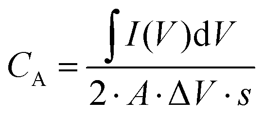 | (1) |
Similarly, the specific capacitance extracted from the galvanostatic charge–discharge curves at constant rates was calculated using eqn (2).
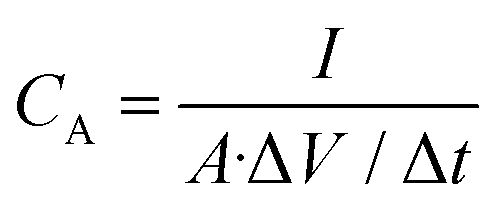 | (2) |
 | (3) |
 | (4) |
LIG synthesis
The laser photothermal process for inducing the nanographene electrodes on the surface of the polyimide was carried out using a CO2 laser with an infrared wavelength of 10.6 μm (Rayjet 50, from Trotec Ltd., Marchtrenk, Austria), as shown in Fig. 1. The laser-scribing process was performed at room temperature and relative humidity using a laser power of 6 W at an engraving speed of 15 cm s−1 to minimize the electrical conductivity of the LIG without compromising the integrity of the substrate, as demonstrated in a previous work.12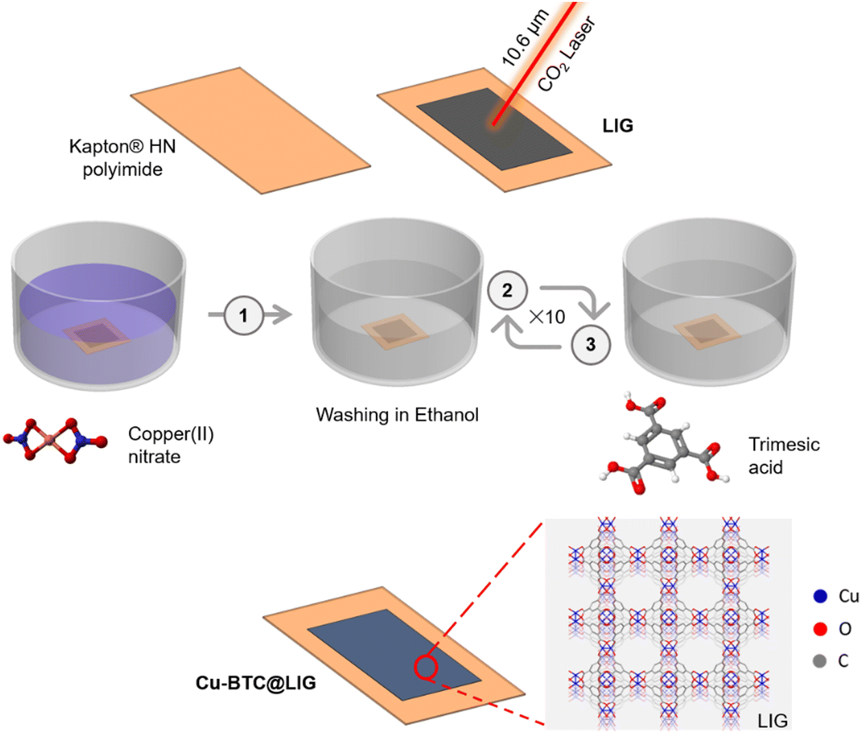 | ||
| Fig. 1 Cu-BTC@LIG electrode fabrication. LIG synthesis by the irradiation of a polyimide with a CO2 laser with a wavelength of 10.6 μm. LIG sheet is immersed alternating in a Cu2+ solution and a H3BTC solution with ethanol washing steps intercalation (10 cycles). | ||
Cu-BTC synthesis
Cu-BTC was synthesized based on a previously reported method.47 A solution of 0.07 g (0.3 mmol) Cu(NO3)2·3H2O was dissolved in 6 mL of ethanol. Then, a solution of 0.126 g (0.6 mmol) of H3BTC in 6 mL of ethanol was added and stirred at room temperature for 1 h. The nanoparticles were then washed with ethanol and collected by centrifugation.Cu-BTC growth over LIG electrodes
The LIG electrodes were activated with 200 mg KOH aqueous solution for 24 h to hydroxylate the graphene surface.48,49 After that, a thin film of Cu-BTC was grown over the LIG electrode based on the Cu-BTC synthesis following a layer-by-layer method.50 Metal and linker solutions were prepared separately but by considering the final stoichiometry of the MOF components. 0.07 g (0.3 mmol) of Cu(NO3)2·3H2O was dissolved in 6 mL of ethanol, and 0.126 g (0.6 mmol) H3BTC in 6 mL ethanol. Cu-BTC was grown on the LIG electrodes by repeated immersion of the electrode in the prepared solutions, as depicted in Fig. 1. Firstly, the electrode was immersed in the copper solution for 5 min and washed by submerging in ethanol (6 mL). Then, the electrode was immersed in the H3BTC solution for 5 min and washed in ethanol (6 mL). This sequence was repeated for 10 cycles to uniformly grow the Cu-BTC crystals all over the LIG surface.Supercapacitor fabrication
Planar supercapacitors with an InterDigital Electrode (IDE) structure were fabricated directly on the surface of the flexible Kapton® HN polyimide following the procedure shown in Fig. 2. In particular, we considered the following dimensions: number total of fingers N = 10, width of the fingers W = 1 mm, spacing between electrodes S = 1 mm, interspacing between fingers i = 1 mm and length of the fingers L = 11 mm, which resulted in a total area of ∼2.3 cm2 (Fig. 2.1). We have also characterized an alternative structure with the same area but by decreasing the interspacing between fingers and the separation between electrodes to 500 μm, thus increasing the number of unit cells (N = 13) and the overall capacitance.51 After the laser-scribing process, Cu-BTC was grown on the surface of the LIG as described in the previous section (Fig. 2.2). After that, electrical Ag/AgCl contacts were screen-printed on each electrode and dried at 60 °C for 30 min (Fig. 2.3). The gel electrolyte was prepared by dissolving 1 g of PVA in 10 mL of deionized water, stirring at 80 °C for 2 h using a hot plate stirrer. Once the PVA was completely dissolved, 1.5 mL of phosphoric acid, H3PO4, was added to the solution and it was stirred for another hour.12,52,53 Finally, 0.5 mL of the resulting PVA/H3PO4 gel electrolyte were drop-cast on top of the IDE structure covering all the effective area, as shown in Fig. 2.4. The final devices were left 48 h under ambient conditions to remove the excess of water before the characterization.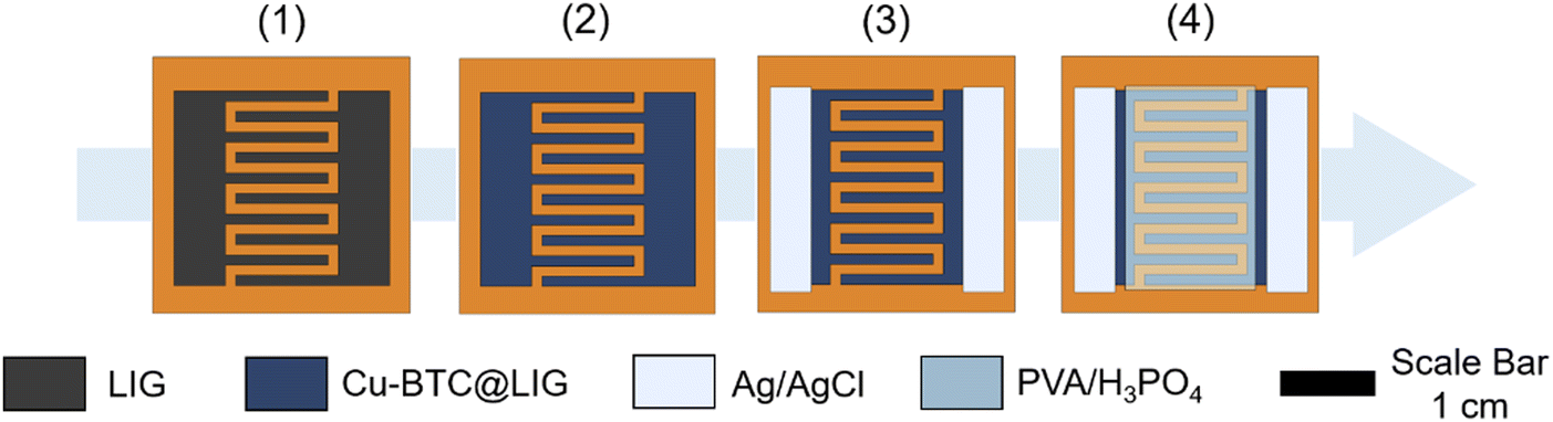 | ||
| Fig. 2 Cu-BTC@LIG supercapacitor fabrication. (1) Laser-synthesis of the interdigital electrodes, (2) Cu-BTC growth on the LIG layer, (3) silver-based electrical contacts printed on each electrode, (4) PVA/H3PO4 electrolyte drop-casted on top of the IDE structure. | ||
Results and discussion
Structural characterization
The formation of the crystalline Cu-BTC phase on the surface of flexible LIG following the procedure described in Fig. 1 was initially demonstrated with the combination of XRD and FTIR (Fig. 3). The FTIR spectrum of Cu-BTC@LIG confirmed the presence of the typical bands found in the spectra of pristine Cu-BTC, as shown in Fig. 3A. In particular, the vibration bands associated with the C–O–Cu bonds at 728 and 1110 cm−1, as well as with the C–C stretching (1450 cm−1) from the benzene rings, and both C–O (1370–1044 cm−1) and C![[double bond, length as m-dash]](https://www.rsc.org/images/entities/char_e001.gif) O (1645 cm−1) bonds from carboxylic acid in the BTC can be observed.54 In the case of the samples with only LIG (inset of Fig. 3A), the main contributions are attributed to the C–C stretching vibration (1618 cm−1) from the benzene ring along with the remaining C–N (1371 cm−1) and C–H (700–1000 cm−1) bonds from the initial polyimide structure.
O (1645 cm−1) bonds from carboxylic acid in the BTC can be observed.54 In the case of the samples with only LIG (inset of Fig. 3A), the main contributions are attributed to the C–C stretching vibration (1618 cm−1) from the benzene ring along with the remaining C–N (1371 cm−1) and C–H (700–1000 cm−1) bonds from the initial polyimide structure.
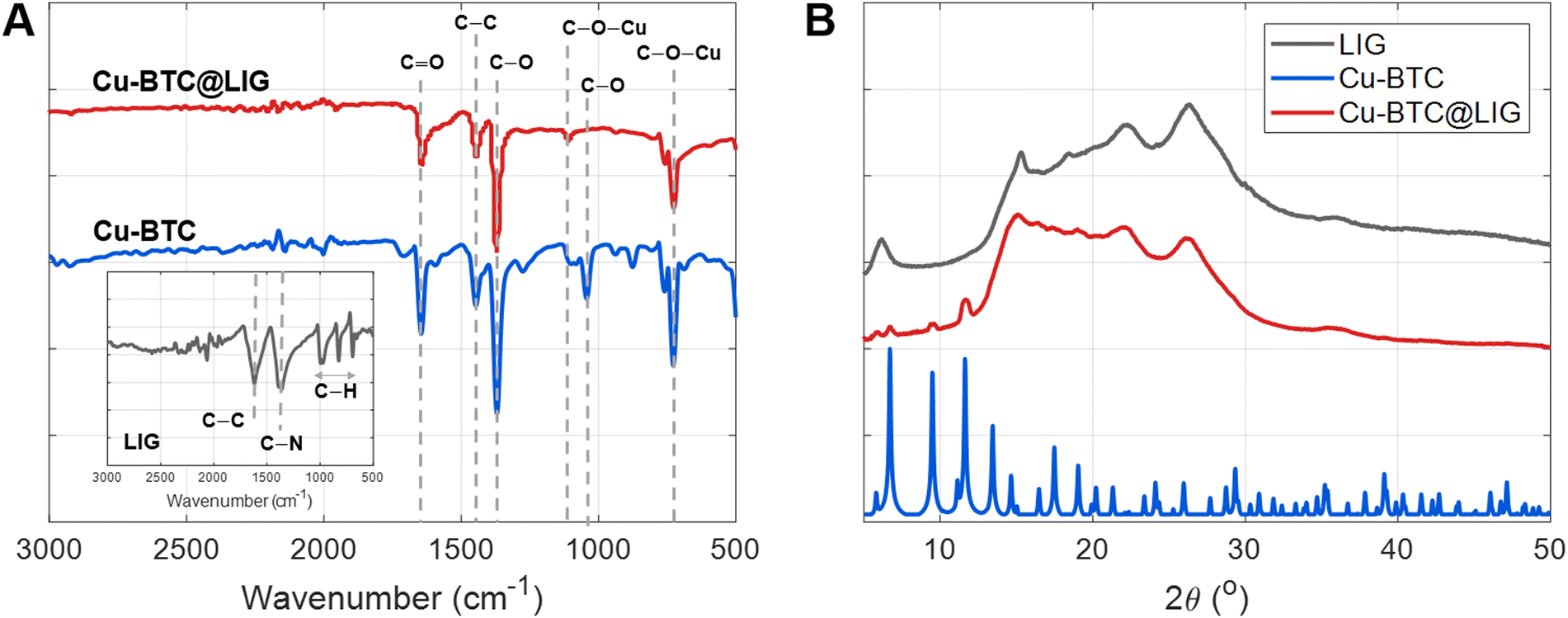 | ||
| Fig. 3 (A) FTIR of synthesized Cu-BTC, LIG, and Cu-BTC@LIG. (B) XRD diffraction patterns of LIG, Cu-BTC and Cu-BTC@LIG. | ||
In the case of the XRD, the diffractogram of LIG, shown in Fig. 3B, exhibits broad bands typically found in graphene-derived materials, such as the (002) peak at 26.5°. The other peaks at lower angles suggest the presence of defects and disorders in the graphene-derived structure, as will be confirmed later by Raman spectroscopy.55 Despite the broad bands in the XRD pattern of the LIG as a consequence of its defective and disordered structure, it is possible to observe the peaks that correspond to the Cu-BTC crystalline structure in the XRD pattern of the Cu-BTC@LIG composites, matching with the results already reported in previous works.54
Moreover, SEM images combined with EDX confirmed the successful deposition of the Cu-BTC within the LIG structure. The characteristic porous surface of LIG (Fig. 4A) is fully covered after the MOF growth with typical octahedron particles (size = 0.6 ± 0.2 μm) of Cu-BTC (Fig. 4B).56 In addition, the elemental mapping obtained by EDX (Fig. 4C–E) demonstrates the uniform distribution of these Cu-containing particles all over the LIG surface.
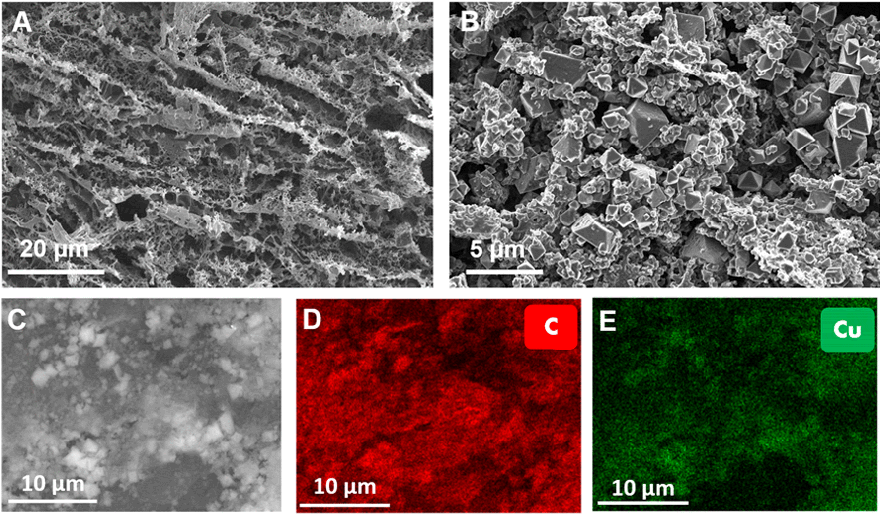 | ||
| Fig. 4 SEM images of the (A) LIG surface and the (B) Cu-BTC@LIG surface. EDX analysis study of the Cu-BTC@LIG surface (C) together with both (D) carbon (red) and (E) copper distribution (green). | ||
Furthermore, Raman experiments confirmed both the successful synthesis of the graphene-derived layer on top of the polyimide surface, and the subsequent successful growth of the Cu-BTC crystals to obtain a Cu-BTC@LIG composite (Fig. 5). The Raman spectrum of LIG is composed of the three main peaks of graphene-derived materials, the D peak located at ∼1350 cm−1, the G peak at ∼1580 cm−1 and the 2nd order D (2D) peak at ∼2700 cm−1. These peaks provide valuable information about the crystallographic quality of the graphene-derived structure. The G peak is always present in graphitic materials, indicating the presence of sp2 hybridized carbon–carbon bonds, while the D peak is activated by the presence of disorders and defects in this carbon sp2 structure. The higher the ID/IG ratio, the higher the concentration of defects. Moreover, the 2D peak is associated with the number of graphitic layers through the I2D/IG ratio and its full width at half maximum (FWHM2D). The rest of the bands (D + D′′, D + D′ and 2D′) are also activated by the defects from the ideal structure of graphite, as reported in previous works.57,58 In single layer graphene, the Raman spectrum would show a ratio ID/IG = 0, indicating the absence of defects in the sp2 hexagonal lattice structure, a ratio I2D/IG of 2–3 and a FWHM2D of ∼30 cm−1. As the number of graphene layers increases, the I2D/IG ratio decreases and the FWHM2D increases.59,60 In our case, the graphene-derived material shows a ID/IG ratio of 0.877, a I2D/IG ratio of 0.789 and a FWHM2D of 70 cm−1, as expected for 3D porous nanographene.59,61 On the other hand, the Raman spectroscopic analysis of Fig. 5B demonstrates that the spectrum of the Cu-BTC@LIG composites matches with the combination of both materials, demonstrating the successful growth of the MOF according to the results presented by Wang et al.62 Regarding the H3BTC ligand, we can identify the bands related to the stretching modes of CC from the benzene rings (1007 and 1614 cm−1), the symmetric and asymmetric stretching modes of CO from the carboxylate units (1463 and 1551 cm−1), and the bands assigned to the bending vibrations and bending modes of out-of-plane C–H located at 744 and 826 cm−1, respectively. Finally, the presence of CuO units is manifested through the band located at 501 cm−1. It can be seen that although the presence of the Cu-BTC functional groups on the surface of the LIG produces a slight increase of defect density (slightly higher ID/IG ratio), the 2D peak does not suffer significant changes, thus indicating that the layer-by-layer process is non-destructive to the LIG platform, as reported in previous works.44
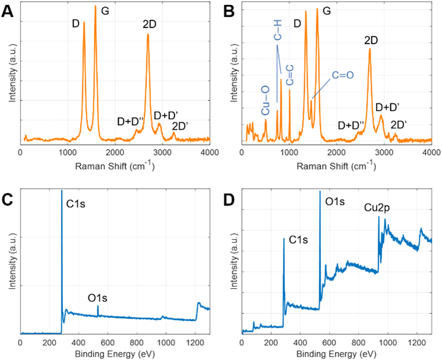 | ||
| Fig. 5 Raman spectra of LIG (A) and Cu-BTC@LIG electrode (B). Wide-scan XPS spectra of LIG (C) and Cu-BTC@LIG electrode (D). | ||
The chemical states of the Cu-BTC@LIG composite have been analyzed by XPS. The results of the wide spectra shown in Fig. 5C and D illustrated the main components present in both LIG and Cu-BTC@LIG electrodes. In the case of LIG, it is mainly composed of carbon (95.7%), with a remaining contribution of oxygen (4.9%) from those carbon–oxygen functional groups of the original Kapton® HN structure that were not broken with the laser photothermal process. As expected, the Cu-BTC coating led to an increase of oxygenation as a consequence of the BTC ligands, as well as to the apparition of the Cu2p contribution, thus demonstrating the co-existence of carbon, oxygen and copper elements in the Cu-BTC@LIG electrode.63–65
The deconvolution of the high-resolution C 1s peak of LIG, Fig. 6A, demonstrates that it is composed mainly of sp2/sp3 hybridized C–C bonds (284.6 eV) with a residual contribution of C–N–C bonds and oxygen-containing groups (C–O–C, CO) from the initial polyimide structure.66,67 The C 1s component of LIG also showed the presence of the π–π* transition, which is a characteristic shake-up line (satellite peak) of sp2 carbon when an excited valence electron is promoted to another valence energy level in the sample.68
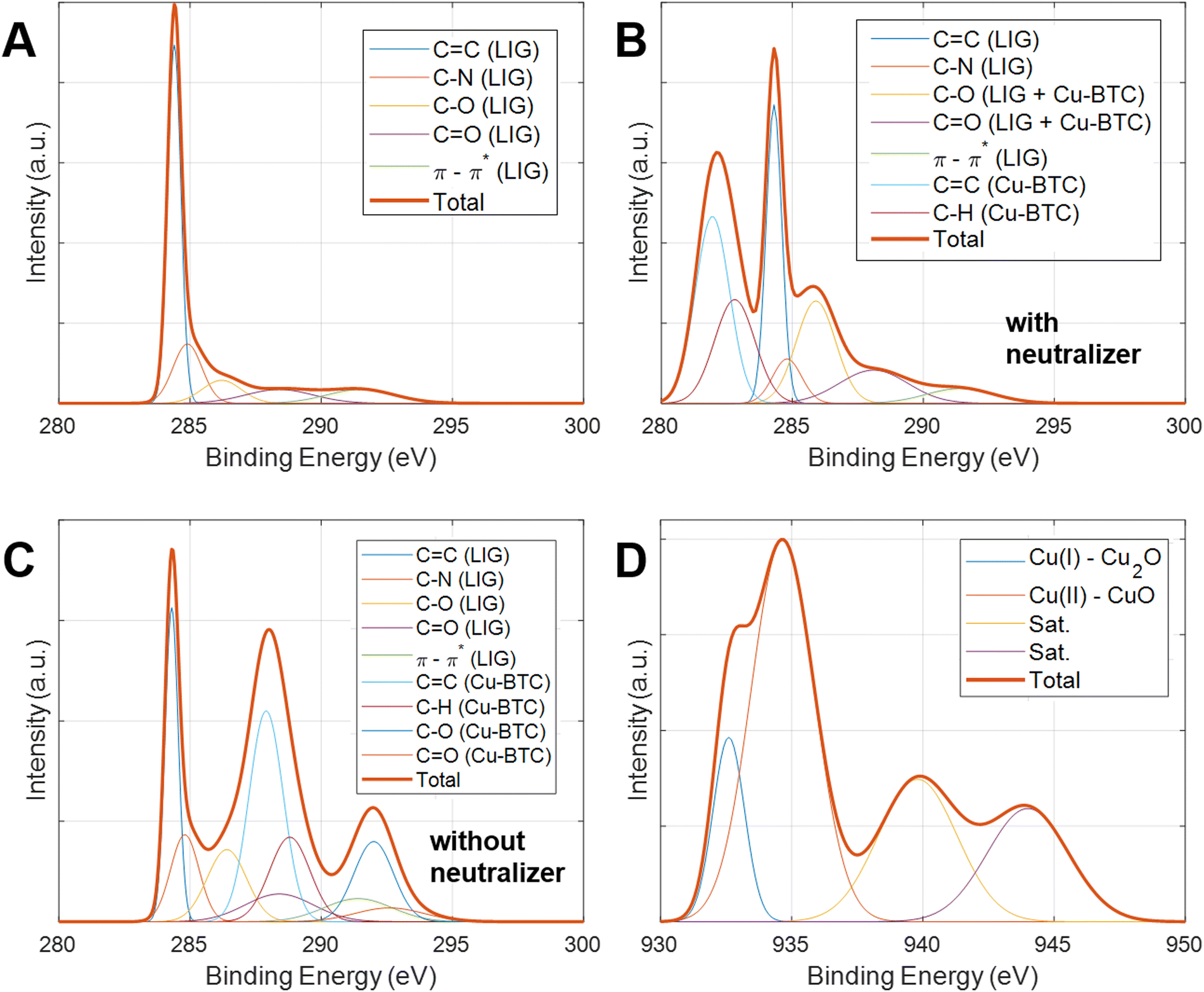 | ||
| Fig. 6 XPS C 1s peaks and their deconvolution for (A) LIG, (B) Cu-BTC@LIG with neutralizer, (C) Cu-BTC@LIG without neutralizer. (D) XPS Cu 2p3/2 peak and its deconvolution for (D) Cu-BTC@LIG composite with neutralizer. | ||
In the case of the Cu-BTC@LIG composite, the contribution of each material to the C 1s peak can be clearly distinguished. Since Cu-BTC is not conductive, we performed the XPS measurements with and without a neutralizer, as shown in Fig. 5B and C. Due to the charge accumulation at the surface and in the interface between materials, these measurements present a shift in the bending energy of the insulating material (Cu-BTC), while the contribution of the conductive material (LIG) remained static.69 From these results we can identify the three main contributions of the Cu-BTC to the C 1s peak: the first contribution is a characteristic of C–C and C–H bonds from the aromatic ring (benzene) of 1,3,5-benzenetricarboxylic acid, while the other two correspond to the C–OH and CO bonds of the carboxyl compounds.70,71 On the other hand, the oxidation states of Cu are also manifested in the Cu region of the XPS spectrum, matching with a Cu 2p3/2 spectra. The deconvolution of this peak shows four different contributions, as shown in Fig. 6D, where the peak at 934.6 eV along with two satellite peaks at 940 and 944 eV is associated with Cu(II) in CuO, and the peak at 932.6 eV with Cu(I) in Cu2O.65,72–74
Electrical and electrochemical performance
The sheet resistance of the laser-scribed patterns was evaluated before and after the Cu-BTC deposition. For that, 10 different LIG square samples (1 cm2) were fabricated, and the sheet resistance measurement process was conducted in the center of the sample, obtaining a result of 113.08 ± 27.71 Ω and 109.67 ± 33.26 Ω for the LIG and Cu-BTC@LIG samples, respectively. These similar results demonstrate that the growth of the insulating Cu-BTC crystals occurs mainly on the surface of the LIG, since the probes penetrate through the Cu-BTC on top of it, making a good electrical contact with the LIG surface, as occurring for the existing native oxide on the semiconductor surfaces.75Cyclic voltammetry curves for both LIG and Cu-BTC@LIG electrodes are shown in Fig. 7A for a scanning rate of 100 mV s−1. As seen, the CV curves of the LIG-only electrodes present a quasi-rectangular shape, indicating a pure electric double-layer capacitance behaviour. However, the inclusion of the Cu-BTC on the surface of the electrode introduces a pseudocapacitive contribution, thus enhancing the overall capacitance (being 2.3 times higher in this case). This increase of the capacitance originates from the conversion between the different copper oxidation states as a consequence of the redox reactions on the surface of the electrode, as also reported by CuO-decorated rGO, LIG/MoS2 composites and MnO2/rGO composite electrodes.76–79
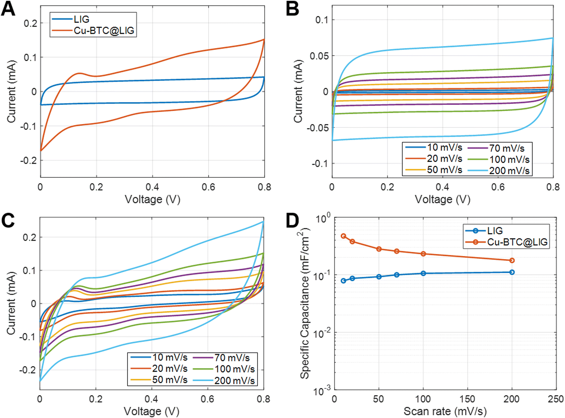 | ||
| Fig. 7 (A) Comparison of the cyclic voltammetry curves at 100 mV s−1 for both LIG and Cu-BTC@LIG electrodes. (B) CV curves at different scan rates for the LIG electrodes. (C) CV curves at different scan rates for the Cu-BTC@LIG electrodes. (D) Specific capacitance as a function of the scan rate for both LIG and Cu-BTC@LIG electrodes. | ||
The different CV curves as a function of the scan rate for both electrodes are shown in Fig. 7B and C, respectively, while their specific capacitance is included in Fig. 7D. This latter figure manifests that the increase in capacitance is especially noticeable at low frequencies, where pseudocapacitance typically plays a more prominent role since there is more time available for the redox reactions to occur. The inclusion of the Cu-BTC in the LIG structure offers an increase of up to 6 times with respect to that obtained with only LIG at 10 mV s−1 (from 78.8 to 473 μF cm−2 at 10 mV s−1), hence outperforming the relative increase obtained for the other functionalized LIG electrodes, as summarized in Table 1.
| LIG functionalizer | Electrolyte | C A increment | Ref. |
|---|---|---|---|
| Cu-BTC | PVA/H3PO4 | 6@10 mV s−1 | This work |
| 2.19@100 mV s−1 | |||
| 5.25@30 μA cm−2 | |||
| Cu | PVA/KOH | 1.34@100 mV s−1 | 13 |
| Ag | 1.5@100 mV s−1 | ||
| N + B + Co | PVA/H2SO4 | 9.35@50 mV s−1 | 80 |
| MoS2 | PVP + NaCl | 3.88@10 mV s−1 | 78 |
| MnO2 | PVA/H3PO4 | 1.5@1 mA cm−2 | 81 |
| B | PVA/H2SO4 | 4@50 μA cm−2 | 82 |
| N | PVA/H2SO4 | 4@50 μA cm−2 | 83 |
| NiO | KOH (aqueous) | 2.33@5 mV s−1 | 84 |
| SnO2 | PVA/H2SO4 | 5.2@10 mV s−1 | 85 |
It can also be observed that, as the frequency increases, the capacitive behavior associated with the electrical double layer at the electrode–electrolyte interface becomes more dominant.86 Despite this, the capacitance provided by the Cu-BTC@LIG electrodes is higher with respect to the only LIG electrodes, as they count with a more available surface for the adsorption of the electrolyte within the porous structure. On the other hand, the galvanostatic charge discharge experiments at constant current included in Fig. 8A–C demonstrated that the Cu-BTC@LIG supercapacitors offer significantly higher energy density than the LIG-based supercapacitors. For instance, for a discharge current of 75 μA, the discharge time for the Cu-BTC@LIG electrodes is 19.468 s, in contrast to the 3.92 s provided by the only-LIG ones, hence indicating a specific capacitance almost five times higher (being consistent with the values extracted from the CV data). The fact that the Cu-BTC@LIG electrodes do not exhibit a quasi-symmetric triangular shape indicates the involvement of Faradaic reaction processes, as demonstrated in other studies.76 Similar to the trend observed with increasing scan rates, Fig. 8C shows that the pseudocapacitive effect makes a lower contribution to the overall specific capacitance as the current density increases. In terms of stability across multiples charge discharge cycles, we can appreciate in Fig. 8D that the specific capacitance provided by the Cu-BTC@LIG composites is higher than that offered by the LIG electrodes, even after 5000 cycles. It is well-known that pseudocapacitive electrodes are compromised by the limited charge–discharge cycling stabilities of the pseudocapacitive material.
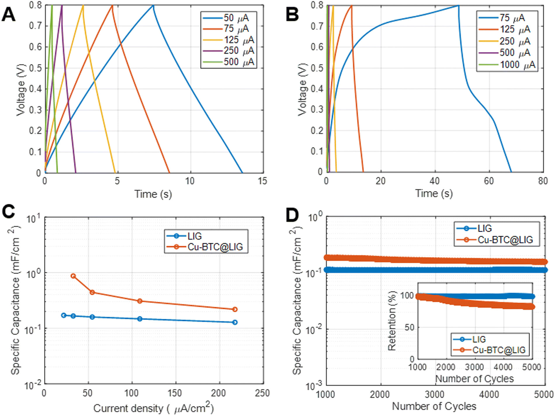 | ||
| Fig. 8 Galvanometric charge–discharge curves at different constant currents for both LIG (A) and Cu-BTC@LIG (B) electrodes. (C) Specific capacitance as a function of the current density for both LIG and Cu-BTC@LIG electrodes. (D) Specific capacitance and capacitance retention (inset) as a function of the number of cycles extracted from CV curves. | ||
Therefore, in the case of the Cu-BTC@LIG electrodes, the specific capacitance decays by around 20% of the original capacitance (inset of Fig. 8D), which is attributed to the degradation of the CuO crystal structure during the ion insertion–extraction process as the number of cycles increase, thus reducing the contribution of the pseudocapacitive effect.87,88
We have summarized in Table 1 the specific capacitance increment achieved for the Cu-BTC@LIG composites with respect to other LIG functionalizers reported in the literature. The comparison of the specific capacitance before and after the functionalization allows for a proper evaluation of the improvement in the capacitance regardless of the capacitive structure design, demonstrating that the Cu-BTC outperforms the relative increase in capacitance obtained for the other functionalized LIG electrodes.
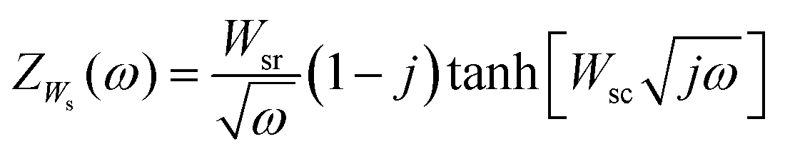
As a disadvantage, the increase in the overall capacitance of the Cu-BTC@LIG electrodes is accompanied by an increase of both distributed and electrical resistances, as demonstrated in the Nyquist plot of the inset in Fig. 9A and B (where the intersection with the x-axis, high frequency, reveals the electric resistance due to the sum of the resistance of the bulk electrolyte, the electrode, and the contact resistance between the electrode and the current collector). At very high frequencies the ions do not have enough time to penetrate inside pores and only the external surface is accessible; hence the resistive components have more influence.89 Since both electrolytes are the same, the increase in this resistance (from 170 to 217 Ω) comes from the fact of having the insulating Cu-BTC crystals on the surface of the LIG. As seen, the Nyquist plot does not show any semicircular region, indicating that the material possesses low Faradaic resistances in the electrode/electrolyte interface.89–91 Alternatively, at intermediate frequencies the Nyquist plot presents an intermediate region with a slope of around 45°, which is associated with the distributed resistance/capacitance in the porous electrode during the electric double layer formation at the electrode/electrolyte interface. Finally, the presence of the pseudocapacitance and the increase of these non-idealities lead to a higher inclination in the low frequency region of the Nyquist plot and to more tilted CV curves.92,93 This behaviour has also been evaluated by extracting the corresponding equivalent circuit from the EIS data of each electrode material. Following the approach presented by Nguyen and Breitkopf,94 we fitted the EIS data to the best suited parameters of an equivalent circuit generated using the software EIS spectrum analyzer. The resulting models for the LIG and Cu-BTC@LIG electrodes are shown in Fig. 9C and D, respectively. Both models consist of a series resistance combined with a modified Randles circuit that represents the pseudocapacitance, and a Randles circuit representing the ECDL capacitance. However, note that in the case of LIG electrodes the Warburg element is an open circuit element, which more accurately represents the reflective boundary of a non-electroactive electrode such as LIG, whereas the Cu-BTC@LIG electrode is modelled with a short-circuit Warburg element to account for diffusion in the electroactive electrode.
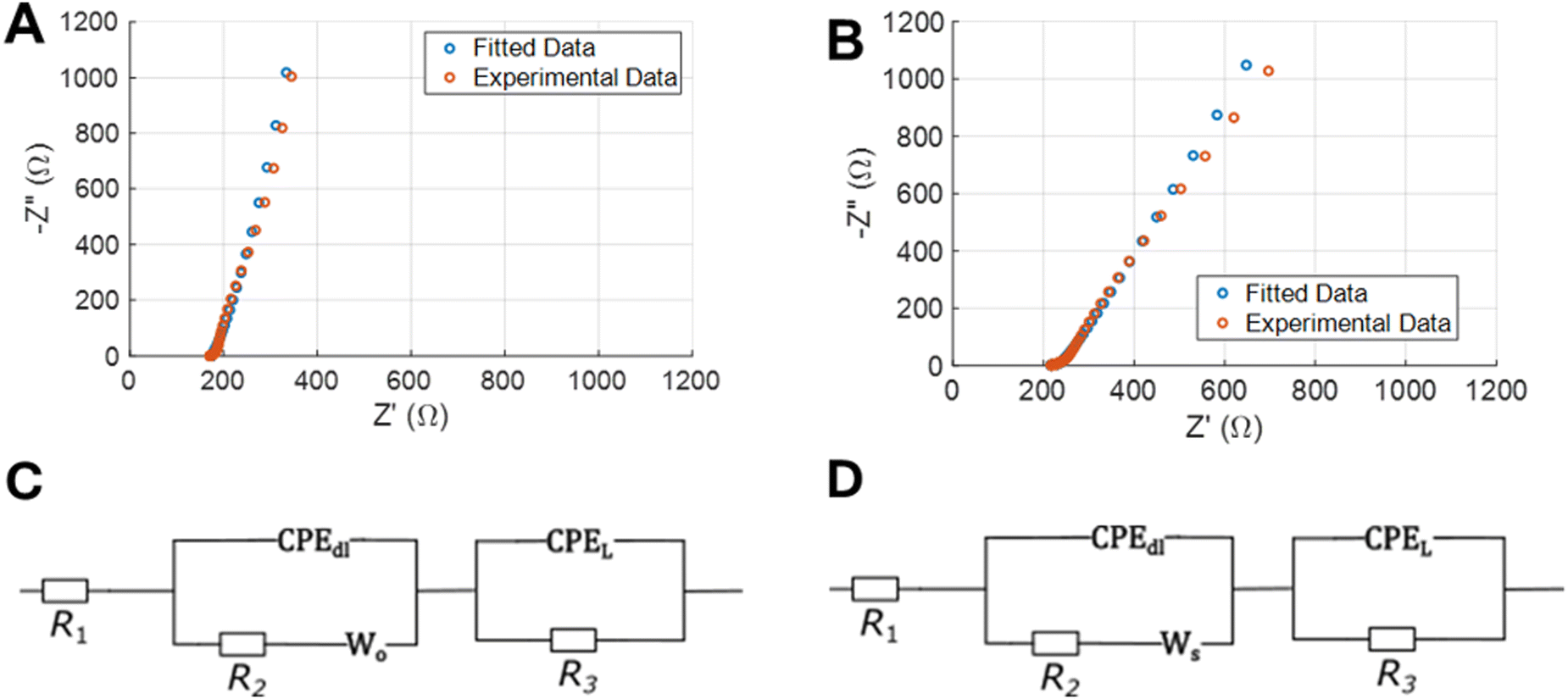 | ||
| Fig. 9 EIS experimental data and fitted curve for LIG (A) and Cu-BTC@LIG (B) electrodes. Equivalent circuits used for the fitting process for both LIG (C) and Cu-BTC@LIG (D). | ||
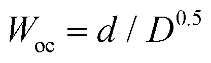
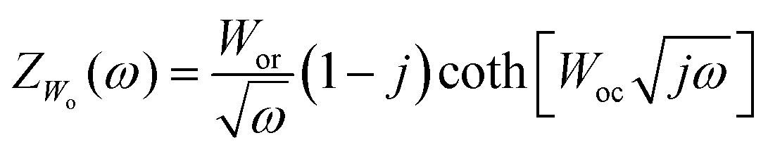
On the one hand, the short circuit Warburg element is defined by eqn (5), where the parameter Wsr is the Warburg coefficient and the parameter 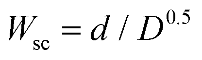 , D and d being the diffusion coefficient and Nernst diffusion layer thickness, respectively.
 | (5) |
 .
. | (6) |
The parameters of the equivalent circuits that provide the fitted EIS data of Fig. 9 are included in Table 2. As introduced before, the insulating Cu-BTC crystals on the surface of the LIG slightly increases the series resistance R1 of the Cu-BTC@LIG supercapacitors. As expected from the previous results, the capacitance CPEL (associated with pseudocapacitance) is higher in the case of Cu-BTC@LIG, while the effect of the ECDL capacitance is lower (CPEdl), which is consistent with the electroactive behaviour of this material. In addition, the charge transfer resistance (R2) is much lower in the case of the Cu-BTC@LIG, indicating a significantly better electrochemical performance thanks to a higher rate of charge transfer between the electrode and the electrolyte. Moreover, the Cu-BTC@LIG electrodes also present a lower Faradaic resistance (R3), thus allowing improved energy densities.95
| Electrode | R 1 (Ω) | R 2 (kΩ) | R 3 (Ω) | CPEdl | W o/Ws | CPEL |
|---|---|---|---|---|---|---|
| LIG | 173.3 | 960 | 339.03 | C dl = 0.0034877 | W or = 37.854 | C L = 0.0024359 |
| n = 0.96994 | W oc = 0.57007 | n = 0.61832 | ||||
| Cu-BTC@LIG | 212.46 | 94.424 | 32.651 | C dl = 0.0018988 | W sr = 268.82 | C L = 0.0057358 |
| n = 0.30398 | W sc = 49.766 | n = 0.81601 |
The higher energy density achieved with the Cu-BTC@LIG electrodes is demonstrated in Fig. 10. In this case, we used an alternative structure with the same area but a higher density of fingers to improve the overall capacitance while maintaining the same behaviour, as demonstrated in the additional CV and galvanostatic charge–discharge experiments included in the ESI† (Fig. S1 and S2). It can be appreciated that with the Cu-BTC functionalization we can achieve an areal energy density up to 7.4 times higher than that provided by the LIG electrodes at a power density of 21.26 μW cm−2, providing a performance similar to that obtained with the N-doped rGO supercapacitors presented by Liu et al.96 The lower performance of Cu-BTC@LIG supercapacitors compared to other LIG-functionalized electrodes, despite exhibiting a higher increase in the specific capacitance, is due to their smaller initial capacitance (before functionalization), as shown in Table S1 (ESI†). Therefore, future studies aim to further optimize the initial capacitive structure to enhance the final power performance of Cu-BTC@LIG supercapacitors relative to other LIG-functionalized devices.
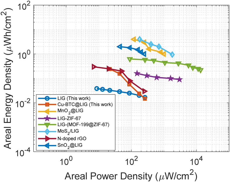 | ||
| Fig. 10 Ragone plot for the LIG and Cu-BTC@LIG electrodes along with other LIG and rGO functionalized electrodes presented in the literature.27,29,78,81,85,96 | ||
Conclusions
This study demonstrates the facile and versatile synthesis of Cu-BTC@LIG composites on flexible substrates. After a one-step laser-photothermal process over the surface of a Kapton® HN polyimide to obtain laser-induced graphene, Cu-BTC crystals are grown within its porous structure following a simple layer-by-layer method. The successful synthesis of a Cu-BTC@LIG composite is demonstrated by multiple characterization techniques, including FTIR, XRD, SEM, Raman and XPS. Cu-BTC@LIG composites exhibit significant promise for various applications because of their large surface area, porosity, and enhanced surface reactions at active sites. Here we have demonstrated its use for enhancing the specific capacitance and energy density of supercapacitors by more than 6 times thanks to the combination of the electrochemical double layer capacitance of LIG along with the pseudocapacitance introduced by the CuO of the Cu-BTC structure. The results presented in this work pave the way for the use of the Cu-BTC@LIG composites not only in energy-storage applications, but also in other flexible electronic applications, such as gas detection and biosensing.Author contributions
Samuel Morales-Camara: investigation, formal analysis, visualization, writing – original draft. victor total: investigation, data curation, validation, writing – review & editing. Iñigo J. Vitorica-Yrezabal: formal analysis, validation, writing – review & editing. Almudena Rivadeneyra: formal analysis, resources, validation, writing – review & editing. Luis Pereira: formal analysis, resources, validation, supervision, writing – review & editing. Sara Rojas: conceptualization, methodology, formal analysis, validation, supervision, writing – original draft. Francisco J. Romero: conceptualization, methodology, investigation, visualization, project administration, writing – original draft.Conflicts of interest
There are no conflicts to declare.Acknowledgements
This work was supported by the Junta de Andalucía – Consejería de Universidad, Investigación e Innovación through the projects ProyExcel_00268 and ProyExcel_00105, as well as by the Spanish Ministry of Sciences and Innovation through the research projects AgroMOFs TED2021-132440B-I00, TED2021-129949A-I00 and CNS2022-13591, and the Ramón y Cajal fellows RYC2019-027457-I and RYC2021-032522-I.References
- A. Nathan, A. Ahnood, M. T. Cole, S. Lee, Y. Suzuki, P. Hiralal, F. Bonaccorso, T. Hasan, L. Garcia-Gancedo, A. Dyadyusha, S. Haque, P. Andrew, S. Hofmann, J. Moultrie, D. Chu, A. J. Flewitt, A. C. Ferrari, M. J. Kelly, J. Robertson, G. A. J. Amaratunga and W. I. Milne, Proc. IEEE, 2012, 100, 1486–1517 Search PubMed
.
- A. K. Geim and K. S. Novoselov, Nat. Mater., 2007, 6, 183–191 CrossRef CAS PubMed
- E. P. Randviir, D. A. C. Brownson and C. E. Banks, Mater. Today, 2014, 17, 426–432 CrossRef CAS
- K. S. Novoselov, V. I. Fal′ko, L. Colombo, P. R. Gellert, M. G. Schwab and K. Kim, Nature, 2012, 490, 192–200 CrossRef CAS PubMed
- W. Kong, H. Kum, S.-H. Bae, J. Shim, H. Kim, L. Kong, Y. Meng, K. Wang, C. Kim and J. Kim, Nat. Nanotechnol., 2019, 14, 927–938 CrossRef CAS PubMed
- S. Park, Nat. Rev. Mater., 2016, 1, 1–2 Search PubMed
- R. Kumar, A. Pérez del Pino, S. Sahoo, R. K. Singh, W. K. Tan, K. K. Kar, A. Matsuda and E. Joanni, Prog. Energy Combust. Sci., 2022, 91, 100981 CrossRef
- Z. Wan, E. W. Streed, M. Lobino, S. Wang, R. T. Sang, I. S. Cole, D. V. Thiel and Q. Li, Adv. Mater. Technol., 2018, 3, 1700315 CrossRef
- J. Lin, Z. Peng, Y. Liu, F. Ruiz-Zepeda, R. Ye, E. L. G. Samuel, M. J. Yacaman, B. I. Yakobson and J. M. Tour, Nat. Commun., 2014, 5, 1–8 Search PubMed
- F. J. Romero, A. Salinas-Castillo, A. Rivadeneyra, A. Albrecht, A. Godoy, D. P. Morales and N. Rodriguez, Nanomaterials, 2018, 8, 517 CrossRef PubMed
- S. L. Silvestre, T. Pinheiro, A. C. Marques, J. Deuermeier, J. Coelho, R. Martins, L. Pereira and E. Fortunato, Flex. Print. Electron., 2022, 7, 035021 CrossRef CAS
- F. J. Romero, D. Gerardo, R. Romero, I. Ortiz-Gomez, A. Salinas-Castillo, C. L. Moraila-Martinez, N. Rodriguez and D. P. Morales, Micromachines, 2020, 11, 555 CrossRef
- J. Yao, L. Liu, S. Zhang, L. Wu, J. Tang, Y. Qiu, S. Huang, H. Wu and L. Fan, Electrochim. Acta, 2023, 441, 141719 CrossRef CAS
- H. Ali, D. Gupta, R. Gupta and N. Verma, Chem. Eng. Process., 2022, 181, 109146 CrossRef CAS
- D. X. Luong, K. Yang, J. Yoon, S. P. Singh, T. Wang, C. J. Arnusch and J. M. Tour, ACS Nano, 2019, 13, 2579–2586 CAS
- F. Tehrani, M. Beltrán-Gastélum, K. Sheth, A. Karajic, L. Yin, R. Kumar, F. Soto, J. Kim, J. Wang, S. Barton, M. Mueller and J. Wang, Adv. Mater. Technol., 2019, 4, 1900162 CrossRef CAS
- S. Jeong, S. Yang, Y. Jae Lee and S. Hyun Lee, J. Mater. Chem. A, 2023, 11, 13409–13418 RSC
- M. Zhai, A. Li and J. Hu, RSC Adv., 2020, 10, 36554–36561 RSC
- K. Jayaramulu, S. Mukherjee, D. M. Morales, D. P. Dubal, A. K. Nanjundan, A. Schneemann, J. Masa, S. Kment, W. Schuhmann, M. Otyepka, R. Zbořil and R. A. Fischer, Chem. Rev., 2022, 122, 17241–17338 CrossRef CAS PubMed
- S. Kitagawa, R. Kitaura and S. Noro, Angew. Chem., Int. Ed., 2004, 43, 2334–2375 CrossRef CAS PubMed
- O. K. Farha, I. Eryazici, N. C. Jeong, B. G. Hauser, C. E. Wilmer, A. A. Sarjeant, R. Q. Snurr, S. T. Nguyen, A. Ö. Yazaydın and J. T. Hupp, J. Am. Chem. Soc., 2012, 134, 15016–15021 CrossRef CAS PubMed
- L. S. Xie, G. Skorupskii and M. Dincă, Chem. Rev., 2020, 120, 8536–8580 CrossRef CAS
- Z. Li, J. Fraile, C. Viñas, F. Teixidor and J. G. Planas, Chem. Commun., 2021, 57, 2523–2526 RSC
- P. Salcedo-Abraira, A. Santiago-Portillo, P. Atienzar, P. Bordet, F. Salles, N. Guillou, E. Elkaim, H. Garcia, S. Navalon and P. Horcajada, Dalton Trans., 2019, 48, 9807–9817 RSC
- X. Deng, S.-L. Zheng, Y.-H. Zhong, J. Hu, L.-H. Chung and J. He, Coord. Chem. Rev., 2022, 450, 214235 CrossRef CAS
- S. Shin, J. W. Gittins, C. J. Balhatchet, A. Walsh and A. C. Forse, Adv. Funct. Mater., 2023, 2308497 CrossRef
- W. Zhang, R. Li, H. Zheng, J. Bao, Y. Tang and K. Zhou, Adv. Funct. Mater., 2021, 31, 2009057 CrossRef CAS
- A. Basu, K. Roy, N. Sharma, S. Nandi, R. Vaidhyanathan, S. Rane, C. Rode and S. Ogale, ACS Appl. Mater. Interfaces, 2016, 8, 31841–31848 CrossRef CAS PubMed
- M. Wang, Y. Ma and J. Ye, J. Power Sources, 2020, 474, 228681 CrossRef CAS
- S. Khoshhal, A. A. Ghoreyshi, M. Jahanshahi and M. Mohammadi, RSC Adv., 2015, 5, 24758–24768 RSC
- A. M. P. Peedikakkal and I. H. Aljundi, ACS Omega, 2020, 5, 28493–28499 CrossRef CAS PubMed
- Y. Yin, H. Zhang, P. Huang, C. Xiang, Y. Zou, F. Xu and L. Sun, Mater. Res. Bull., 2018, 99, 152–160 CrossRef CAS
- N. A. Travlou, K. Singh, E. Rodríguez-Castellón and T. J. Bandosz, J. Mater. Chem. A, 2015, 3, 11417–11429 RSC
- J. Cheng, X. Xuan, X. Yang, J. Zhou and K. Cen, RSC Adv., 2018, 8, 32296–32303 RSC
- Y. Sun, M. Ma, B. Tang, S. Li, L. Jiang, X. Sun, M. Que, C. Tao and Z. Wu, J. Alloys Compd., 2019, 808, 151721 CrossRef CAS
- A. Allahbakhsh, Z. Jarrahi, G. Farzi and A. Shavandi, Chem. Eng. J., 2023, 467, 143472 CrossRef CAS
- S. Jyotsna Sahoo, B. Barik, B. Maji, P. S. Nayak, N. Behera and P. Dash, J. Electroanal. Chem., 2023, 943, 117589 CrossRef CAS
- R. Darabi and H. Karimi-Maleh, Adv. Compos. Hybrid Mater., 2023, 6, 114 CrossRef CAS
- A. Choudhury, S. Anand, A. Syed, A. H. Bahkali, L. S. Wong, K. B. Yoon, D.-J. Yang and Md. W. Ahmad, Diamond Relat. Mater., 2024, 141, 110613 CrossRef CAS
- P. Arul and S. A. John, J. Electroanal. Chem., 2017, 799, 61–69 CrossRef CAS
- J. Tu, Y. Yuan, H. Jiao and S. Jiao, RSC Adv., 2014, 4, 16380–16384 RSC
- C. Rogier, G. Pognon, P. Bondavalli, C. Galindo, G. T. M. Nguyen, C. Vancaeyzeele and P.-H. Aubert, Surf. Coat. Technol., 2020, 384, 125310 CrossRef CAS
- V. Stavila, A. A. Talin and M. D. Allendorf, Chem. Soc. Rev., 2014, 43, 5994–6010 RSC
- H. Lim, H. Kwon, H. Kang, J. E. Jang and H.-J. Kwon, Nat. Commun., 2023, 14, 3114 CrossRef CAS PubMed
- Y. Chen, X. Zhang, D. Zhang, P. Yu and Y. Ma, Carbon, 2011, 49, 573–580 CrossRef CAS
- M. Klem, R. Abreu, T. Pinheiro, J. Coelho, N. Alves and R. Martins, Electrochemical Deposition of Manganese Oxide on Paper-Based Laser-Induced Graphene for the Fabrication of Sustainable High-Energy Density Supercapacitors, Social Science Research Network (SSRN), 2024 DOI:10.2139/ssrn.4724436.
- J. Huo, M. Brightwell, S. E. Hankari, A. Garai and D. Bradshaw, J. Mater. Chem. A, 2013, 1, 15220–15223 RSC
- Y. Tadjenant, N. Dokhan, A. Barras, A. Addad, R. Jijie, S. Szunerits and R. Boukherroub, Chemosphere, 2020, 258, 127316 CrossRef CAS PubMed
- L. Yan, M. Lin, C. Zeng, Z. Chen, S. Zhang, X. Zhao, A. Wu, Y. Wang, L. Dai, J. Qu, M. Guo and Y. Liu, J. Mater. Chem., 2012, 22, 8367–8371 RSC
- V. Stavila, J. Volponi, A. M. Katzenmeyer, M. C. Dixon and M. D. Allendorf, Chem. Sci., 2012, 3, 1531–1540 RSC
- J. Oberländer, Z. B. Jildeh, P. Kirchner, L. Wendeler, A. Bromm, H. Iken, P. Wagner, M. Keusgen and M. J. Schöning, Sensors, 2015, 15, 26115–26127 CrossRef PubMed
- J.-Y. Shieh, S.-H. Zhang, C.-H. Wu and H. H. Yu, Appl. Surf. Sci., 2014, 313, 704–710 CrossRef CAS
- Y. Houeix, F. J. Romero, C. L. Moraila, A. Rivadeneyra, N. Rodriguez, D. P. Morales and A. Salinas-Castillo, Appl. Surf. Sci., 2023, 634, 157629 CrossRef CAS
- A. M. Varghese, K. S. K. Reddy and G. N. Karanikolos, Ind. Eng. Chem. Res., 2022, 61, 6200–6213 CrossRef CAS
- J.-U. Lee, C.-W. Lee, S.-C. Cho and B.-S. Shin, Nanomaterials, 2021, 11, 3093 CrossRef CAS PubMed
- J. Gu, J. Li and Q. Ma, Nanomaterials, 2022, 12, 1134 CrossRef CAS PubMed
- M. S. Seehra, V. Narang, U. K. Geddam and A. B. Stefaniak, Carbon, 2017, 111, 380–385 CrossRef CAS PubMed
- L. G. Cançado, A. Jorio, E. H. M. Ferreira, F. Stavale, C. A. Achete, R. B. Capaz, M. V. O. Moutinho, A. Lombardo, T. S. Kulmala and A. C. Ferrari, Nano Lett., 2011, 11, 3190–3196 CrossRef PubMed
- J.-B. Wu, M.-L. Lin, X. Cong, H.-N. Liu and P.-H. Tan, Chem. Soc. Rev., 2018, 47, 1822–1873 RSC
- S. Karamat, S. Sonuşen, Ü. Çelik, Y. Uysallı, E. Özgönül and A. Oral, Prog. Nat. Sci.: Mater. Int., 2015, 25, 291–299 CrossRef CAS
- J. Zhu, X. Guo, H. Wang and W. Song, J. Mater. Sci., 2018, 53, 12413–12420 CrossRef CAS
- Y. Wang, W. Cao, L. Wang, Q. Zhuang and Y. Ni, Microchim. Acta, 2018, 185, 315 CrossRef PubMed
- D. Ji, H. Zhou, Y. Tong, J. Wang, M. Zhu, T. Chen and A. Yuan, Chem. Eng. J., 2017, 313, 1623–1632 CrossRef CAS
- S. Hao and Y. Liu, J. Mater. Sci., 2022, 57, 1689–1702 CrossRef CAS
- P. Gao, X.-Y. Sun, B. Liu, H.-T. Lian, X.-Q. Liu and J.-S. Shen, J. Mater. Chem. C, 2018, 6, 8105–8114 RSC
- M. Khandelwal, C. V. Tran and J. B. In, Appl. Surf. Sci., 2022, 576, 151714 CrossRef CAS
- F. J. Romero, A. Rivadeneyra, A. Salinas-Castillo, A. Ohata, D. P. Morales, M. Becherer and N. Rodriguez, Sens. Actuators, B, 2019, 287, 459–467 CrossRef CAS
- G. H. Major, N. Fairley, P. M. A. Sherwood, M. R. Linford, J. Terry, V. Fernandez and K. Artyushkova, J. Vac. Sci. Technol., A, 2020, 38, 061203 CrossRef CAS
- D. R. Baer, K. Artyushkova, H. Cohen, C. D. Easton, M. Engelhard, T. R. Gengenbach, G. Greczynski, P. Mack, D. J. Morgan and A. Roberts, J. Vac. Sci. Technol., A, 2020, 38, 031204 CrossRef CAS
- X. Li, H. Liu, X. Jia, G. Li, T. An and Y. Gao, Sci. Total Environ, 2018, 621, 1533–1541 CrossRef CAS PubMed
- S. Fleutot, H. Martinez, J. C. Dupin, I. Baraille, C. Forano, G. Renaudin and D. Gonbeau, Solid State Sci., 2011, 13, 1676–1686 CrossRef CAS
- A. Ahmed, C. M. Robertson, A. Steiner, T. Whittles, A. Ho, V. Dhanak and H. Zhang, RSC Adv., 2016, 6, 8902–8905 RSC
- X. Li, W. Kong, X. Qin, F. Qu and L. Lu, Microchim. Acta, 2020, 187, 325 CrossRef CAS PubMed
- S. Liu, H. Hou, X. Liu, J. Duan, Y. Yao and Q. Liao, Ionics, 2017, 23, 1075–1082 CrossRef CAS
- M. C. Benjamin, R. J. Hillard and J. O. Borland, Nucl. Instrum. Methods Phys. Res., Sect. B, 2005, 237, 351–355 CrossRef CAS
- I. Y. Y. Bu and R. Huang, Ceram. Int., 2017, 43, 45–50 CrossRef CAS
- D. Majumdar, J. Electroanal. Chem., 2021, 880, 114825 CrossRef CAS
- F. Clerici, M. Fontana, S. Bianco, M. Serrapede, F. Perrucci, S. Ferrero, E. Tresso and A. Lamberti, ACS Appl. Mater. Interfaces, 2016, 8, 10459–10465 CrossRef CAS PubMed
- F. Rahmanabadi, P. Sangpour and A. A. Sabouri-Dodaran, J. Electron. Mater., 2019, 48, 5813–5820 CrossRef CAS
- M. Khandelwal, C. V. Tran, J. Lee and J. B. In, Chem. Eng. J., 2022, 428, 131119 CrossRef CAS
- S. Xi, X.-W. Gao, X.-M. Cheng and H.-L. Liu, New Carbon Mater., 2023, 38, 913–924 CrossRef CAS
- Z. Peng, R. Ye, J. A. Mann, D. Zakhidov, Y. Li, P. R. Smalley, J. Lin and J. M. Tour, ACS Nano, 2015, 9, 5868–5875 CrossRef CAS PubMed
- K. Y. Kim, H. Choi, C. V. Tran and J. B. In, J. Power Sources, 2019, 441, 227199 CrossRef CAS
- N. M. Shaalan, S. Kumar, F. Ahmed, N. Arshi, S. Dalela and K. H. Chae, Nanomaterials, 2023, 13, 2081 CrossRef CAS PubMed
- C. Zhu, X. Dong, X. Mei, M. Gao, K. Wang and D. Zhao, Appl. Surf. Sci., 2021, 568, 150978 CrossRef CAS
-
S. N. Pronkin, N. Yu Shokina and C. Pham-Huu, in Redox Chemistry - From Molecules to Energy Storage, ed. O. Fontaine, IntechOpen, 2022 Search PubMed
- Z. Endut, M. Hamdi and W. J. Basirun, Thin Solid Films, 2013, 528, 213–216 CrossRef CAS
- T. Liu and Y. Li, InfoMat, 2020, 2, 807–842 CrossRef CAS
- P. Navalpotro, M. Anderson, R. Marcilla and J. Palma, Electrochim. Acta, 2018, 263, 110–117 CrossRef CAS
- T. Purkait, G. Singh, D. Kumar, M. Singh and R. S. Dey, Sci. Rep., 2018, 8, 640 CrossRef PubMed
- B.-A. Mei, O. Munteshari, J. Lau, B. Dunn and L. Pilon, J. Phys. Chem. C, 2018, 122, 194–206 CrossRef CAS
- Z. Lei, N. Christov and X. S. Zhao, Energy Environ. Sci., 2011, 4, 1866–1873 RSC
- C.-W. Huang and H. Teng, J. Electrochem. Soc., 2008, 155, A739 CrossRef CAS
- T. Q. Nguyen and C. Breitkopf, J. Electrochem. Soc., 2018, 165, E826 CrossRef CAS
- D. Qu, G. Wang, J. Kafle, J. Harris, L. Crain, Z. Jin and D. Zheng, Small Methods, 2018, 2, 1700342 CrossRef
- S. Liu, J. Xie, H. Li, Y. Wang, H. Y. Yang, T. Zhu, S. Zhang, G. Cao and X. Zhao, J. Mater. Chem. A, 2014, 2, 18125–18131 RSC
Footnote |
| † Electronic supplementary information (ESI) available. See DOI: https://doi.org/10.1039/d4tc00558a |
| This journal is © The Royal Society of Chemistry 2024 |