
 Open Access Article
 This Open Access Article is licensed under a
 Creative Commons Attribution 3.0 Unported Licence
Microfluidic-driven short peptide hydrogels with optical waveguiding properties†
Ana M.
Garcia
 *a,
Juan A.
Garcia-Romero
a,
Sara H.
Mejias
bc,
Pilar
Prieto
a,
Vittorio
Saggiomo
d,
Aldrik H.
Velders
ad,
M. Laura
Soriano
e,
Victor
Ruiz-Díez
f,
Juan
Cabanillas-González
*b and
M. Victoria
Gomez
*a
*a,
Juan A.
Garcia-Romero
a,
Sara H.
Mejias
bc,
Pilar
Prieto
a,
Vittorio
Saggiomo
d,
Aldrik H.
Velders
ad,
M. Laura
Soriano
e,
Victor
Ruiz-Díez
f,
Juan
Cabanillas-González
*b and
M. Victoria
Gomez
*a
aFacultad de Ciencias y Tecnologías Químicas, Instituto Regional de Investigación Científica Aplicada (IRICA), Universidad de Castilla-La Mancha, Ciudad Real 13071, Spain. E-mail: AnaM.Garcia@uclm.es; mariavictoria.gomez@uclm.es
bMadrid Institute for Advances Studies, IMDEA Nanociencia, Calle Faraday 9, Ciudad Universitaria de Cantoblanco, Madrid 28049, Spain. E-mail: juan.cabanillas@imdea.org
cCentro Nacional de Biotecnología (CNB-CSIC)-IMDEA Nanociencia Associated Unit “Unidad de Nanobiotecnología”, Cantoblanco, Madrid 28049, Spain
dLaboratory of BioNanoTechnology, Wageningen University, Wageningen 6700 EK, The Netherlands
eAffordable and Sustainable Sample Preparation (AS2P) Research Group, Departamento de Química Analítica, Instituto Químico para la Energía y el Medioambiente (IQUEMA), Universidad de Córdoba, Campus de Rabanales, Edificio Marie Curie, Córdoba E-14071, Spain
fMicrosystems, Actuators and Sensors Group, INAMOL-Universidad de Castilla La-Mancha, 45004, Toledo, Spain
First published on 11th April 2024
Abstract
Soft photonic elements with optical waveguiding ability based on biocompatible hydrogels have become increasingly important in optical techniques for medical diagnosis and phototherapy, among others. Supramolecular hydrogels based on peptides with interesting optical properties are rarely reported and explored. Although robust crystals based on short peptides have shown optical waveguiding capabilities, their rigidity is the main issue to overcome in the quest for soft biocompatible materials. Here, we report on the microfluidic-assisted formation of a heterochiral short peptide hydrogel that exhibits active optical waveguiding properties thanks to the incorporation of two different dyes, thioflavin T and rhodamine B, into the hydrogel structure. Using our microfluidic platform, different parameters such as the concentration of a peptide, type of dye and its concentration, and flow rate have been rapidly explored, with remarkable low reagent consumption. In this way, it was possible to develop peptide hydrogel waveguides with good optical loss values, modulating the emission in diverse spectral regions. The use of microfluidics to prepare these hydrogels makes possible the preparation of structures of high length-to-diameter aspect ratios, which otherwise are hard to devise from bulk conditions. Overall, this work broadens the use of supramolecular self-assembly of peptides to create functional materials with additional versatility to polymeric hydrogels, thanks to the possibility of tuning the structure by changing amino acid sequences. Additionally, the optical properties can be easily modulated by quick optimization of experimental parameters via microfluidic technology.
Introduction
Light-based technologies have experienced a rapid and substantial development in the last 20 years with application in telecommunications, medicine, lasers or solar cells. In this framework, photonic materials have gained a very active position in promoting the development of modern photonic devices, where optical waveguides are key elements.1 Optical waveguides are physical structures capable of confining and transmitting light with minimal losses, offering the possibility to manipulate light guiding.2 A number of crystals based on π-conjugated organic molecules3,4 and on short peptides5–7 or amino acids8 showing optical waveguiding behaviour have been reported. In this sense, diphenylalanine (Phe–Phe) crystals doped with Nile Red were the first short peptide assemblies that demonstrated waveguiding of the dye luminescence along the crystals.5 Other sequences studied are Phe–Phe cyclic peptides,6 triphenylalanine7 and more recently single amino acids such as tyrosine.8 Optical probes such as Nile Red and rhodamine B (RhB) are incorporated during the crystallization process giving rise to active optical waveguiding materials. Photoactive short peptide assemblies offer advantages such as their ease of preparation, biocompatibility and functional flexibility, being front-runners for the next-generation optical materials to fill the gap between optics and biology.9The promising results obtained on the optical waveguiding ability of short peptide crystals make it appealing to study other types of peptide assemblies such as supramolecular hydrogels, which are a softer, more flexible alternative to their crystal partners. In fact, softer photonic elements based on biocompatible polymers and hydrogels have become increasingly important due to the growing interest in optical techniques for medical diagnosis and treatment.10–13 In this context, supramolecular peptide-based hydrogels with interesting optical features have been described for the first time using Fmoc-diphenylalanine as the building block. Gelation is achieved thanks to the incorporation of the N-capping Fmoc group that increases hydrophobicity in the final structure.14 The optical properties observed for this short peptide hydrogel suggest its potential for optical waveguiding applications.15 An alternative strategy developed to prepare short peptide hydrogels consists of introducing D-amino acids at selected positions in L-tripeptides as it promotes water channel formation that favours hydrogelation.16 The first reports date back to 2012, where the introduction of a D-amino acid at the N-terminus of a hydrophobic sequence bearing the Phe–Phe motif led to rapid gelation under physiological conditions, whereas the L-tripeptide analogue did not gel.17,18 In this tripeptide system, gelation is achieved by a pH trigger from alkaline to neutral in phosphate buffer. This gelation strategy does not need the use of the rigid Fmoc group with concerns in terms of biocompatibility.19 Moreover, the peptide sequence and the combination of chirality chosen determine the long-range supramolecular order achieved in the final hydrogelator.20
An effective approach that may allow a fine control in the preparation of supramolecular short peptide hydrogels is the use of microfluidic technologies. Recent studies have indicated that microfluidic systems provide unique advantages to trigger controlled self-assembly of supramolecular structures on flow.21–23 The well-controlled supply of reagents due to the laminar flow regime present in the reduced-scale fluidic channels enables the contact between solutions, which is governed by diffusion.24 This diffusion mechanism together with the confinement afforded by microchannels, with specific size and shape, exerts a fine control on the way molecules can self-organize at the microscale. In this context, microfluidics represents a valuable tool for the controlled growth, manipulation and processing of self-assembled materials at surfaces, where the generation of a controlled reaction–diffusion environment governs the formation of supramolecular fibers.22 In this sense, Wilson and coworkers used planar extensional flow in cross-slot shaped devices to create aligned 1D supramolecular structures made of oligopeptides containing π-conjugated cores.25 Apart from the device shape, the self-assembly can also be modulated through the fine control of parameters such as a flow rate or solvent, enabling space and time control of the system.22 This reduced-scale technology is also gaining attention as a useful tool to prepare supramolecular peptide assemblies of different types.26–30 However, the microfluidic devices reported in those studies are still developed with soft lithography and therefore, specialized techniques are required for its fabrication, not accessible to all laboratories.
Despite several examples of optical waveguiding hydrogels made of natural/synthetic polymers being reported, supramolecular peptide-based hydrogels have not yet been studied in this manner, even though they offer the possibility to easily modulate both the emission wavelength using dyes as molecular probes and the supramolecular structure by changing amino acid sequences. To this end, a well-controlled self-assembly approach is needed to obtain hydrogels with the appropriate length to diameter ratio, which is quite challenging when they are prepared in bulk (e.g., mixing solutions in a vial).
We here report a microfluidic-based methodology to control the preparation of supramolecular hydrogels using the heterochiral tripeptide DLeu–LPhe–LPhe in biocompatible aqueous media, using two different dyes, thioflavin T (ThT) and rhodamine B (RhB), as optical probes to study the optical properties of the fluorescent hydrogels formed. Using a two-inlet microfluidic device offers the possibility for in situ mixing of two buffer solutions introduced through different inlets, whereby the laminar flow favours the diffusion of molecules and the formation of the hydrogel at the interface of these solutions. The extension of the diffusion can be simply modulated by the flow rate which, interestingly, influences the optical properties of the supramolecular assemblies. Thus, the optimization of the experimental conditions (flow rate, peptide concentration and dye concentration) at this microscale enables the control of the formation of short-peptide hydrogels with novel optical waveguiding properties. On the whole, the microfluidic methodology leads to better control in the self-assembly process compared with bulk (classical conditions),19 rendering fibrils with a high length-to-diameter aspect ratio that enabled the study of their optical waveguiding properties.
Results and discussion
Preparation of peptide hydrogels using microfluidics
The polydimethylsiloxane (PDMS)/glass microfluidic chips used in this work were prepared using oxygen plasma and replica molding, as previously reported (see the Experimental section).31 Their fabrication by 3D printing technology provides a cost-effective and facile fluid handling and high control of the experimental conditions. Our microfluidic devices are constructed by fabricating a positive mold with an SLA (stereolithography) or a masked (SLA) 3D printer that serves as a template to produce the PDMS positive replica in the desired shape. Then, the PDMS replica and the glass surfaces are activated in a plasma oven and subsequently sealed together.31 This replica molding strategy facilitates its implementation as open technology since it is a reliable and cost-effective methodology that can be developed in many laboratories as it does not require a specialist's time. This allows a quick iterative design, fabrication and testing process within 24 hours, as desired for microfluidic technology implementation.31–34The tripeptide DLeu–LPhe–LPhe is able to self-assemble in microfluidic channels (Fig. 1a). The optimization of the total flow rate to 1 µL min−1 rendered the formation of the DLeu–LPhe–LPhe hydrogel along the whole 1.4 cm-length of the central microfluidic channel (V = 14 µL) in a continuous flow regime (Fig. 1a and Fig. S1 and S2, ESI†). Interestingly, the total length of the hydrogel can be tuned on-demand using devices with a different central channel length (Fig. S3, ESI†). It is noted to mention that the use of microfluidics allows good reproducibility in the formation of these fibers, thanks to the well-controlled supply of reagents due to the laminar flow that controls the pH trigger. It is worth stating that the formation of hydrogels inside a microfluidic device using a known gelator as this tripeptide is far from trivial. This is because the system features offer a kinetic control not achieved when preparing hydrogels under bulk conditions, as previously observed in the literature,18,35,36 where microfluidics enable divergent structural features than that offered under the classical conditions.22,23,37,38
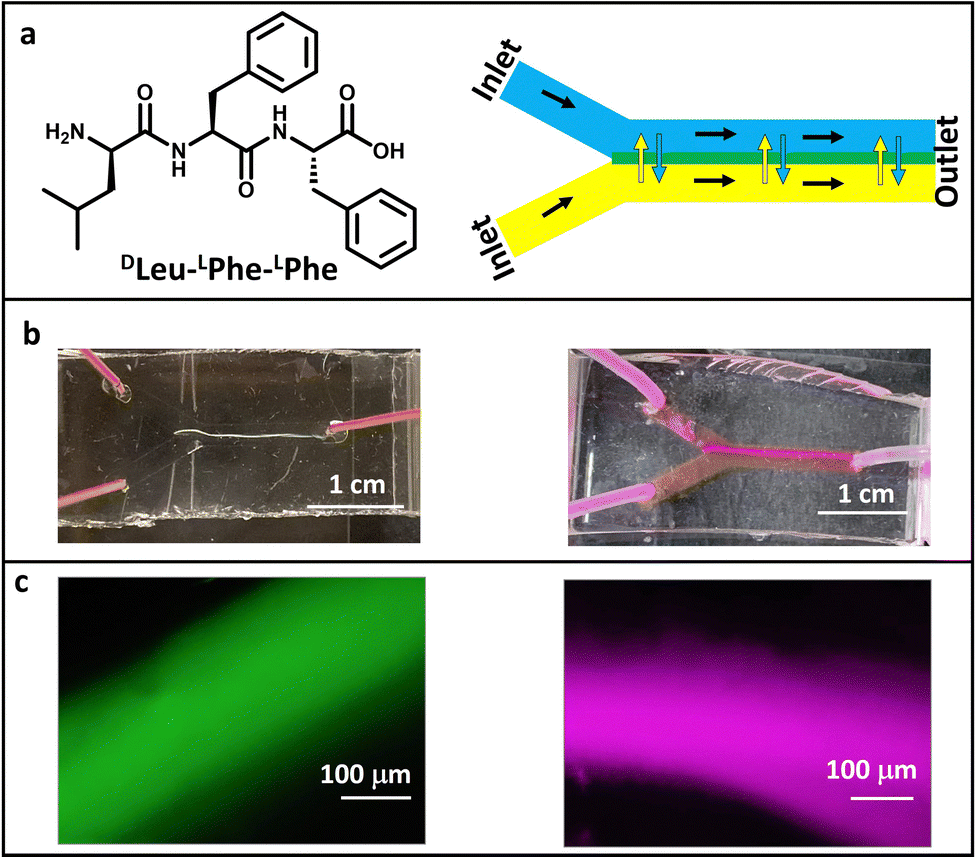 | ||
| Fig. 1 (a) Chemical structure of the tripeptide used in this work (left) and a scheme of a microfluidic device (right). Solution 1 (the peptide dissolved in alkaline phosphate buffer, depicted in blue) and buffer 2 (acidic phosphate buffer, depicted in yellow) are mixed in the central channel of the device. Diffusion between both solutions occurs at their interface, where the peptide hydrogel is formed (depicted in green). The black arrows show the flow direction, and the yellow/blue double-arrow represents the diffusion of molecules at the interface. (b) Photographs and (c) fluorescence microscopy images of the peptide hydrogels formed in microfluidics in the presence of ThT (left panel) and RhB (right panel) under the optimal conditions (10 µL of ThT stock 1 mg mL−1 in 200 µL of acidic phosphate buffer and 5 µL of RhB stock 0.5 mg mL−1 in 200 µL of each phosphate buffer); peptide solution concentration of 16 mM; flow rate of 1 µL min−1. | ||
Monitoring of peptide hydrogel formation
The formation of the hydrogels inside the microfluidic channel can be monitored in situ by fluorescence microscopy when they are prepared in the presence of a dye. To this end, self-assembly was performed in the presence of ThT, which leads to enhanced fluorescence in the presence of a β-sheet type structure (10 µL of a ThT solution 1 mg mL−1 was added to the 200 µL of acidic buffer, peptide/ThT molar ratio 102, see the Experimental section).18,39 Self-assembly occurred at different concentrations of the peptide, being 8 mM the minimum concentration of peptide solution introduced through one of the inlets of the device that allow hydrogel formation, although less porous and more robust materials were formed when the peptide concentration was doubled (Fig. 1b and c and Fig. S4, ESI†). The different experimental parameters were optimized to exploit the advantages offered by microfluidic technology to create self-assembled systems rapidly and consuming low amount of reagents. Thus, the flow rate was also modified (from 1 µL min−1 to 0.5 µL min−1 and 0.3 µL min−1), maintaining the constant peptide solution concentration at 16 mM and the ThT stock concentration at 1 mg mL−1 (a peptide-to-dye molar ratio of 102, see the Experimental section). Although these flow rates resulted in the formation of the hydrogel, they rendered more porous, wider and shorter structures with more structural defects as shown by fluorescence microscopy and their corresponding photographs (Fig. S5, ESI†). These findings demonstrate that the self-assembled structures obtained are affected by the flow conditions and only an optimum flow rate renders hydrogel formation at the interface along the whole length of the central channel.24 Regarding the dye, increasing the ThT concentration to 2 mg mL−1, whilst keeping the rest of parameters constant (i.e. flow rate and peptide concentration), enables hydrogel formation (Fig. S6, ESI†), while a further increase to 5 mg mL−1 impedes self-assembly formation in the microchannels. Lower ThT concentrations (0.5 mg mL−1) led to hydrogel formation too (Fig. S6, ESI†), although differences in the optical properties were observed, as will be shown below.Next, RhB was used as dye instead of ThT, in order to tune the emission wavelength of the waveguide. Fluorescent hydrogels were obtained using stock solutions with 0.25, 0.5 and 1 mg mL−1 RhB concentrations (Fig. 1b and c and Fig. S7 (ESI†), 5 µL of RhB solution was added to each 200 µL of phosphate buffer solution, see the Experimental section), although the latter concentration displayed severe aggregation-induced quenching. These results demonstrated the high versatility of this tripeptide to self-assemble in the presence of other molecules using microfluidics, as previously shown under bulk conditions.35,36,40,41
Characterization of peptide hydrogels
Hydrogels formed in the microfluidic devices were characterized using Raman spectroscopy to obtain insights into the structure of the self-assembled peptide systems. The peptide hydrogel was also prepared under bulk conditions to compare its Raman spectra with the self-assembled system prepared using microfluidics (see the Experimental section). The Raman spectrum of the peptide powder (non-assembled) was also recorded as a control. Raman analysis confirmed the β-sheet-structure arrangement observed in the microfluidic-prepared hydrogel similar to that observed in the hydrogel assembled under bulk conditions, in agreement with previous reports on self-assembling heterochiral ultra-short peptides (Fig. 2a).41–44 The amide I region displayed a Raman peak at 1692 cm−1 that indicates the presence of a hydrogen bonding pattern typical for β-type stacks, in both the classical and the microfluidic-directed assembled hydrogels, together with another peak at ∼1641 cm−1 that corresponds to the C![[double bond, length as m-dash]](https://www.rsc.org/images/entities/char_e001.gif) O stretching. These two Raman modes are fingerprints of self-assembly, as they are absent in the peptide powder spectrum,44 in agreement with previous reports.41 The Raman fingerprint does not change in the presence of ThT or RhB, implying that incorporating these dyes does not change the molecular arrangement of DLeu–LPhe–LPhe hydrogels (Fig. S8, ESI†).45
O stretching. These two Raman modes are fingerprints of self-assembly, as they are absent in the peptide powder spectrum,44 in agreement with previous reports.41 The Raman fingerprint does not change in the presence of ThT or RhB, implying that incorporating these dyes does not change the molecular arrangement of DLeu–LPhe–LPhe hydrogels (Fig. S8, ESI†).45
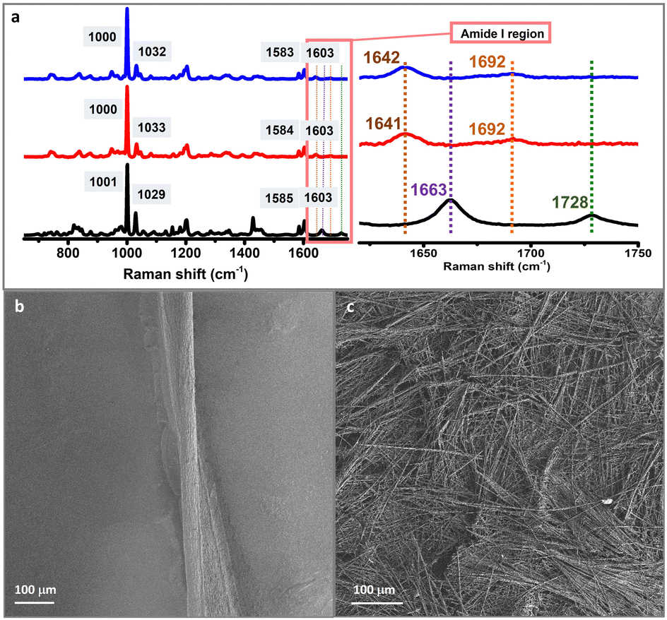 | ||
| Fig. 2 (a) Raman spectra of DLeu–LPhe–LPhe hydrogels obtained under bulk conditions (red) or using microfluidics (blue), and the peptide powder (non-assembled) (black). The four Raman active modes for aromatic rings are depicted in grey squares. The amide I region is expanded to show the differences in the structural arrangement between the powder and the assembled structures. SEM images of DLeu–LPhe–LPhe hydrogels formed (b) under bulk conditions and (c) in microfluidic devices. | ||
The morphology of the hydrogels was assessed with scanning electron microscopy (SEM). A twisted microfluidic-driven fibre of 220 ± 20 µm width is formed using microfluidics (Fig. 2b). It is composed of thinner fibrils parallelly aligned forming a bundle. This controlled orientation is clearly in contrast with an analogue hydrogel obtained in a standard vessel (bulk conditions) (Fig. 2c and Fig. S9, ESI†). The latter displays a heterogeneous morphology composed of interconnected fibrils forming a network with a random orientation. In this way, the precise control and manipulation of small volumes of fluids afforded by microfluidics leads to a controlled alignment of fibrils along the specific channel length.
Study of optical waveguiding properties
The formation of luminescent hydrogel fibres obtained by microfluidics of a large length-to-diameter ratio led us next to the study of the photoluminescence waveguiding properties. This is highly interesting given that these properties have been only addressed so far in peptide-based microcrystals, which do not possess the flexibility and soft structure of hydrogel fibres. Here, other related studies on dye-doped microcrystals of short peptides based on Nile Red5 or Rhodamine B serve as examples.45 In our case, we selected ThT and RhB as they are stable under the experimental conditions used and they allow tuning the emission at different wavelengths (Fig. 3).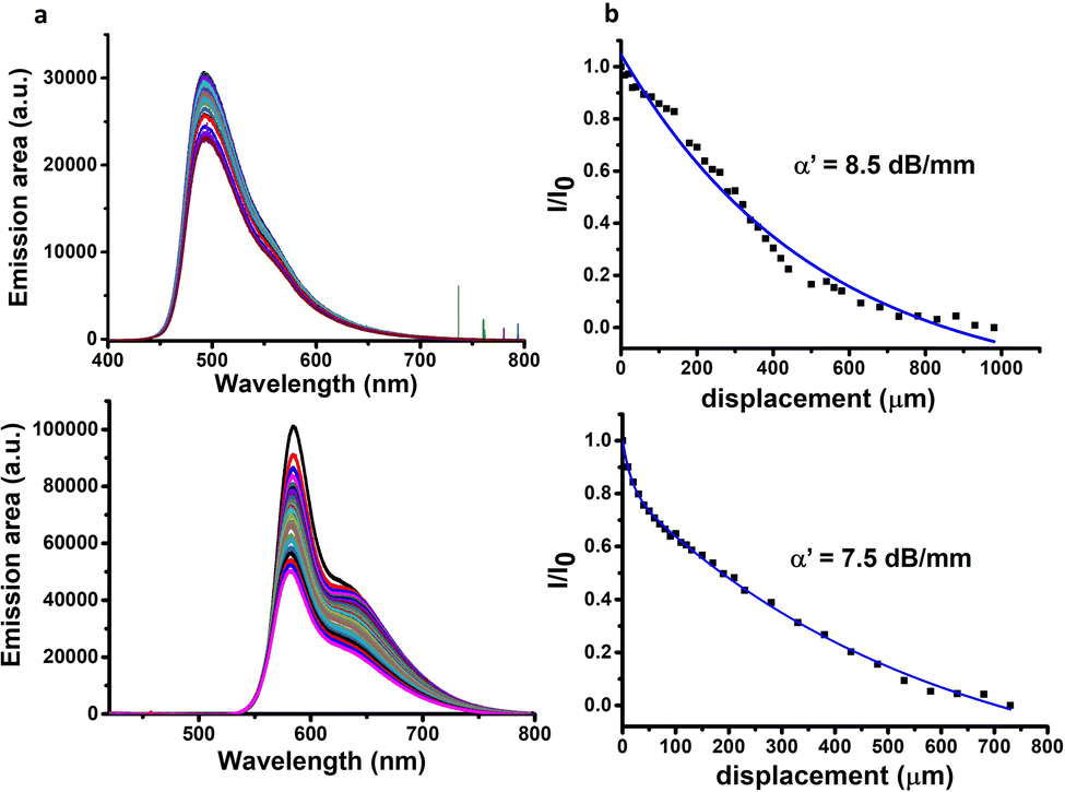 | ||
| Fig. 3 (a) PL spectra of fibres collected at the end tip upon varying the distances between the excitation and the tip of the fibre. (b) Ratio between the PL intensities photoexcited at the initial (Io) and intermediate (I) positions along the fibre as a function of distance (λexc = 355 nm). Top panel: ThT as the dye. Bottom panel: RhB as the dye. | ||
When excitation of light at 355 nm is focused on a precise point of the hydrogel fibre, a bright photoluminescence (PL) spot is obtained at this fibre end, with almost negligible emission along the body (Fig. S10, ESI†). This phenomenon is typical for optical waveguiding materials. The excitation–detection distance dependent PL intensity was evaluated for each system prepared with the two dyes (Fig. 3a and Fig. S11–S14, ESI†). To this end, fluorescence spectra were recorded upon photoexciting at different positions along the fibre axis and detecting at one of the fibre tips. Analysis of the intensity dependence as a function of photoexcitation – detection distance allowed the estimation of the optical loss coefficient (α′) in dB mm−1 for each sample (Fig. 3b and Fig. S11–S14 (ESI†), see the Experimental section for details).
The optical loss obtained for the hydrogels using ThT and RhB as optical probes (for their respective optimum dye concentrations) at the lower peptide solution concentration used (8 mM) was quite high indicating that light transmission is not very efficient (Table 1, entries 1 and 7 and Fig. S11, ESI†). However, when the peptide concentration was doubled, the optical loss decreased dramatically (Table 1, entries 2 vs. 1 and 8 vs. 7, Fig. 3b and Fig. S11, ESI†). We attributed this enhancement in the light transmission to a decrease in the porosity of the fibrillar structure at higher peptide concentrations. Less porosity decreases the light scattering in the material favouring, thus, the light transmission. This occurs even when the hydrogels present a similar supramolecular arrangement at both concentrations ofpeptide.
| Entry | Dye | C peptide (mM) | C dye (mg mL−1) | Peptide/dye molar ratioc | Flow rate (µL min−1) | α′ (dB mm−1) |
|---|---|---|---|---|---|---|
| a C peptide refers to the initial concentration of the peptide in alkaline phosphate buffer (PB) solution pumped through one of the inlets of the microfluidic device (Fig. 1a). b C dye refers to the initial concentration of ThT or RhB in the stock solution of the dye. 10 µL of ThT solution was added in 200 µL of acidic PB buffer, and 5 µL of RhB solution was added in 200 µL of each PB buffer (see Experimental section for details). c Molar ratio refers to µmol of the peptide to µmol of the dye employed in each experiment of hydrogel formation at the Cpeptide and Cdye indicated in each entry. | ||||||
| 1 | ThT | 8 | 1 | 51 | 1 | 590.0 |
| 2 | ThT | 16 | 1 | 102 | 1 | 8.5 |
| 3 | ThT | 16 | 2 | 51 | 1 | 13.0 |
| 4 | ThT | 16 | 0.5 | 204 | 1 | 18.1 |
| 5 | ThT | 16 | 1 | 102 | 0.5 | 26.0 |
| 6 | ThT | 16 | 1 | 102 | 0.3 | 26.1 |
| 7 | RhB | 8 | 0.5 | 153 | 1 | 1172.0 |
| 8 | RhB | 16 | 0.5 | 305 | 1 | 7.5 |
| 9 | RhB | 16 | 0.25 | 610 | 1 | 18.0 |
Furthermore, the dye concentration was varied for both ThT and RhB, where changes in the optical loss values were also evident. The optimal values for optical loss coefficients were found when using ThT and RhB stock solutions of 1 mg mL−1 and 0.5 mg mL−1, respectively (Table 1, entries 2 and 8, respectively, Fig. 3). Increasing the concentration of ThT to 2 mg mL−1 or lowering it to 0.5 mg mL−1 has a negative impact on the optical loss coefficient of the hydrogel (Table 1, entries 3 and 4 respectively and Fig. S12, ESI†). The same trend is observed when the RhB concentration decreases from 0.5 to 0.25 mg mL−1 (Table 1, entry 8 vs. entry 9 and Fig. S13, ESI†).
Finally, the impact of the flow rate on the optical properties of these hydrogels was studied, revealing that the optical loss coefficient increases as the flow rate decreases (Table 1, entry 2 vs. entries 5 and 6 and Fig. S14, ESI†). The lower the flow rate, the more porous and wider the assemblies are, as shown by fluorescence microscopy (Fig. 1vs. Fig. S5, ESI†) and SEM images (Fig. 2bvs. Fig. S15, ESI†). This has a detrimental impact on light transmission, most probably because of light scattering, one of the most critical optical loss mechanisms in biomaterials due to their porous structure.10
These results show that the assembled structures formed along the microfluidic channel possess active optical waveguiding ability when using ThT and RhB as dyes, being RhB needed at a lower concentration than ThT, in view of its higher fluorescence quantum yield (0.4 and 0.7 for ThT bound to amyloid fibrils46,47 and for RhB,48 respectively). In addition, the versatility of this tripeptide to self-assemble in conjunction with any of the dyes makes possible the development of luminescent waveguide structures capable to emit in different regions of the spectra, enabling the adjustment of the emission of the optical waveguides on demand.
Overall, it is important to highlight that the peptide concentration is the parameter having the higher impact on optical guiding, as the higher porosity found at lower concentrations led to poorer light propagation through the supramolecular fibrillar structure. This is because the supramolecular arrangement in the hydrogel structure is the key for the optical waveguiding behaviour, and this is mainly defined by the peptide sequence and chirality combination,20 as well as its concentration in the hydrogel. In addition, microfluidics has enabled to identify the experimental conditions (peptide concentration, dye concentration and flow rate) to achieve the hydrogel with the adequate structure and morphology to obtain better values of the optical loss coefficient. Furthermore, the optical loss coefficient found for the best conditions using ThT (8.5 dB mm−1, Table 1, entry 2) and RhB (7.5 dB mm−1, Table 1, entry 8) is in the order of that described for certain soft, biocompatible PEG hydrogels (0.017–2.5 dB mm−1)49,50 or even lower than that recently found for flexible microfibers from lotus silk (51 dB mm−1).51 Although some of the former hydrogels show optical loss values that are sometimes below 0.1 dB mm−1, it is important to remark that the strategy developed in this work allows engineering properties through chemical synthesis by changing amino acid sequences, which cannot be performed so easily with polymeric hydrogels.
Conclusions
In conclusion, this work describes the microfluidic-assisted preparation of supramolecular hydrogels of a short heterochiral peptide using homemade PDMS/glass microfluidic devices, allowing a quick, low-cost screening of multiple experimental conditions (e.g., peptide concentration, flow rate, and dye concentration) to fine tune the material properties. Microfluidic technology rendered possible hydrogel structures with high length-to-diameter aspect ratios, opening new avenues to exploit these short peptide hydrogels. Incorporation of ThT and RhB as dyes into these supramolecular systems led to the formation of fluorescent peptide hydrogels that behave as macroscopic active optical waveguiding biomaterials with emission in different spectral regions. This optical phenomenon is a consequence of the long-range supramolecular order presented by this peptide hydrogel, which functions as an optical microcavity,6 thus allowing the propagation of photoluminescence emission along the longitudinal axis. This novel photonic feature identified in this type of peptide-based hydrogel represents an interesting property to provide materials that will contribute to the future development of integrated biomedical optics, allowing light-based diagnosis and precise phototherapy.52In addition, short peptides enable a large diversity of supramolecular structures upon changing amino acid sequences thanks to chemical synthesis. These assets pave the way to create diverse self-assembled peptide systems with defined functional properties, enabling on-demand design and multiple size and shape possibilities.
Experimental section
Materials and methods
Tripeptide DLeu–LPhe–LPhe was purchased from DG peptides.Sodium hydroxide and hydrochloric acid were supplied by Scharlau and Sigma Aldrich, respectively. Phosphate buffer solutions at pH 12 and 5.8 were supplied by Fisher Scientific.
A pH bench meter (electrochemical sensor XS) was purchased from VioLab.
High purity Milli-Q-water (MQ water) with a resistivity greater than 18 M Ω cm was obtained from an in-line Millipore RiOs/Origin system. SYLGARD silicone elastomer 184 and its curing agent were obtained from Ellworth.
Fabrication of microfluidic devices
A 3D mold was designed in Tinkercad (Autocad) and printed with an mSLA 3D printer (Prusa SLS) or an SLA one (Formlabs Form 3) using Prusa tough resin and Formlab clear V4 resin, respectively. After 3D printing, the mold was washed with ethanol and isopropanol and then allowed to dry. For easy peeling of the PDMS, the 3D printed molds were covalently coated with trichloro (1H,1H,2H,2H-perfluorooctyl)silane (PFOTS, 97%) using chemical vapor deposition (CVD) in a vacuum desiccator. The 3D printed structure was air plasma-activated for 30 s, and then, it was placed in a desiccator with a vial of 100 µL of PFOTS and high vacuum was applied using the pump. For the plasma treatment, an Inseto Plasma Etch, Inc. PE-25 benchtop air plasma cleaner was used at its maximum RF plasma power of 100 W with an air flow of ∼10 cc min−1, which allowed for a vacuum pressure of 200–250 mTorr within the chamber during plasma treatment. The desiccator was then left under a static vacuum for overnight CVD of PFOTS. After deposition, the 3D printed structure was removed from the desiccator and left in the oven at 70 °C for 1 h, then it was washed with ethanol and isopropanol.PDMS replicas were prepared by pouring the PDMS degassed mixture (10![[thin space (1/6-em)]](https://www.rsc.org/images/entities/char_2009.gif) :1 silicone elastomer to curing agent) on the 3D printed PFOTS coated mold. After overnight curing at 70 °C, the PDMS was cut out the mold and sonicated in ethanol for 4 minutes to remove the small molecular weight and unreacted PDMS chains. The PDMS replica was then dried with nitrogen. An inlet and outlet were then created on the edges of the microchannel features by puncturing through the PDMS with a 1.0 mm ∅ or 1.5 mm ∅ punch (KAI, Japan).
:1 silicone elastomer to curing agent) on the 3D printed PFOTS coated mold. After overnight curing at 70 °C, the PDMS was cut out the mold and sonicated in ethanol for 4 minutes to remove the small molecular weight and unreacted PDMS chains. The PDMS replica was then dried with nitrogen. An inlet and outlet were then created on the edges of the microchannel features by puncturing through the PDMS with a 1.0 mm ∅ or 1.5 mm ∅ punch (KAI, Japan).
The PDMS replica was placed facing upwards in the plasma oven with a clean microscope glass slide. The slide and the PDMS replica were treated in a plasma oven (see above for details). After this, the PDMS replica was firmly placed on the glass slide, and the microfluidic was left in the oven at 70 °C overnight.
Formation of peptide hydrogels
Peptide hydrogel formation in the presence of dyes (thioflavin T and rhodamine B). Experiments were carried out as described for hydrogel formation, while dyes were incorporated as follows: in the case of ThT, 10 µL of a stock solution at the concentration indicated in each experiment (2, 1 or 0.5 mg mL−1) was added in 200 µL of acidic phosphate buffer; while for RhB, 5 µL of a stock solution at the concentration indicated in each experiment (0.5 or 0.25 mg mL−1) was added in 200 µL of each buffer (alkaline and acidic phosphate buffers, injected through inlets 1 and 2, respectively). All dye solutions were filtered (0.45 µm) before use.
:1 with another 150 µL of 0.1 M sodium phosphate buffer (pH 5.6–5.7) to yield a final pH ∼7.4 that triggers the hydrogel formation. All buffer solutions were filtered (0.45 µm) before use.
Author contributions
A. M. G.: conceptualization, investigation, data curation, funding acquisition, and writing – original draft and review and editing. J. A. G.-R.: investigation and data curation. S. H. M.: investigation, data curation, and resources. P. P.: conceptualization and writing – review and editing. V. S.: investigation, methodology, and writing – review and editing. A. H. V.: methodology and writing – review and editing. M. L. S.: investigation and methodology. V. R.-D.: investigation and resources. J. C.-G.: methodology, resources, and writing – review and editing. M. V. G.: conceptualization, investigation, methodology, funding acquisition, project administration, supervision, and writing – original draft and review and editing.Conflicts of interest
There are no conflicts to declare.Acknowledgements
S. H. M., P. P., J. C.-G. and M. V. G. acknowledge the MICINN-FEDER (Projects PID2020-119636GB-I00 funded by the MCIN/AEI/10.13039/501100011033, CTQ2017-84825-R, PID2021-128313OB-I00 and TED2021-131906A-I00). A. M. G., P. P. and M. V. G. acknowledge the Junta de Comunidades de Castilla-La Mancha (JCCM-FEDER) (Projects SBPLY/21/180501/000114 and SBPLY/21/180501/000206 and SBPLY/21/180501/000088) and Programa FEDER Castilla-La Mancha 2021-2027 (2022-GRIN-34310). A. M. G. acknowledges the María Zambrano program under the grant agreement UNI/551/2021. S. H. M. acknowledges her fellowship from the ““La Caixa” Foundation (ID 100010434)”. The fellowship code is LCF/BQ/PI22/11910022. J. C. G. acknowledges support by the Regional Government of Madrid (NMAT2D-CM). J. C. G. also acknowledges a Research Consolidation Grant (CNS2022-136191) from the Spanish Ministry of Science and Innovation. IMDEA Nanociencia acknowledges support from the ‘Severo Ochoa’ Programme for Centres of Excellence in R&D of the Spanish Ministry of Science and Innovation (CEX2020-001039-S).References
- Y. Yan and Y. S. Zhao, Chem. Soc. Rev., 2014, 43, 4325–4340 RSC.
- Y. Ma, Y. Zong, H. Yin, H. Lin, S. Chen and X. D. Wang, Adv. Opt. Mater., 2021, 9, 2101481 CrossRef CAS.
- X. Yang, L. Lan, X. Pan, X. Liu, Y. Song, X. Yang, Q. Dong, L. Li, P. Naumov and H. Zhang, Nat. Commun., 2022, 13, 7874 CrossRef CAS PubMed.
- S. Chen, M. P. Zhuo, X. D. Wang, G. Q. Wei and L. S. Liao, PhotoniX, 2021, 2, 2 CrossRef.
- X. Yan, J. Li and H. Möhwald, Adv. Mater., 2011, 23, 2796–2801 CrossRef CAS PubMed.
- X. Yan, Y. Su, J. Li, J. Früh and H. Möhwald, Angew. Chem., Int. Ed., 2011, 50, 11186–11191 CrossRef CAS PubMed.
- B. Apter, I. Lapsker, A. Inberg and G. Rosenman, Adv. Opt. Mater., 2022, 10, 2102342 CrossRef CAS.
- Y. Zhang, Q. Li, H. Wu, Y. Wang, Y. Wang, S. Rencus-Lazar, Y. Zhao, J. Wang, D. Mei, H. Xu, E. Gazit and K. Tao, ACS Nano, 2023, 17, 2737–2744 CrossRef CAS PubMed.
- B. Sun, K. Tao, Y. Jia, X. Yan, Q. Zou, E. Gazit and J. Li, Chem. Soc. Rev., 2019, 48, 4387–4400 RSC.
- S. Shabahang, S. Kim and S. H. Yun, Adv. Funct. Mater., 2018, 28, 1706635 CrossRef PubMed.
- D. Shan, E. Gerhard, C. Zhang, J. W. Tierney, D. Xie, Z. Liu and J. Yang, Bioact. Mater., 2018, 3, 434–445 Search PubMed.
- J. Feng, Y. Zheng, S. Bhusari, M. Villiou, S. Pearson and A. del Campo, Adv. Funct. Mater., 2020, 30, 2004327 CrossRef CAS.
- C. Pons, J. M. Galindo, J. C. Martín, I. Torres-Moya, S. Merino, M. A. Herrero, E. Vázquez, P. Prieto and J. A. Vallés, Micromachines, 2022, 13, 2253 CrossRef PubMed.
- K. Tao, A. Levin, L. Adler-Abramovich and E. Gazit, Chem. Soc. Rev., 2016, 45, 3935–3953 RSC.
- N. Amdursky, E. Cazit and G. Rosenman, Adv. Mater., 2010, 22, 2311–2315 CrossRef CAS PubMed.
- A. M. Garcia, D. Iglesias, E. Parisi, K. E. Styan, L. J. Waddington, C. Deganutti, R. De Zorzi, M. Grassi, M. Melchionna, A. V. Vargiu and S. Marchesan, Chem, 2018, 4, 1862–1876 CAS.
- S. Marchesan, C. D. Easton, F. Kushkaki, L. Waddington and P. G. Hartley, Chem. Commun., 2012, 48, 2195–2197 RSC.
- S. Marchesan, L. Waddington, C. D. Easton, D. A. Winkler, L. Goodall, J. Forsythe and P. G. Hartley, Nanoscale, 2012, 4, 6752–6760 RSC.
- W. T. Truong, Y. Su, D. Gloria, F. Braet and P. Thordarson, Biomater. Sci., 2015, 3, 298–307 RSC.
- S. Marchesan, K. E. Styan, C. D. Easton, L. Waddington and A. V. Vargiu, J. Mater. Chem. B, 2015, 3, 8123–8132 RSC.
- J. Puigmartí-Luis, M. Rubio-Martínez, U. Hartfelder, I. Imaz, D. Maspoch and P. S. Dittrich, J. Am. Chem. Soc., 2011, 133, 4216–4219 CrossRef PubMed.
- S. Sevim, A. Sorrenti, C. Franco, S. Furukawa, S. Pané, A. J. Demello and J. Puigmartí-Luis, Chem. Soc. Rev., 2018, 47, 3788–3803 RSC.
- D. Khoeini, T. F. Scott and A. Neild, Lab Chip, 2021, 21, 1661–1675 RSC.
- J. Puigmartí-Luis, D. Schaffhauser, B. R. Burg and P. S. Dittrich, Adv. Mater., 2010, 22, 2255–2259 CrossRef PubMed.
- A. B. Marciel, M. Tanyeri, B. D. Wall, J. D. Tovar, C. M. Schroeder and W. L. Wilson, Adv. Mater., 2013, 25, 6398–6404 CrossRef CAS PubMed.
- T. O. Mason, T. C. T. Michaels, A. Levin, E. Gazit, C. M. Dobson, A. K. Buell and T. P. J. Knowles, J. Am. Chem. Soc., 2016, 138, 9589–9596 CrossRef CAS PubMed.
- Z. A. Arnon, A. Vitalis, A. Levin, T. C. T. Michaels, A. Caflisch, T. P. J. Knowles, L. Adler-Abramovich and E. Gazit, Nat. Commun., 2016, 7, 1–7 Search PubMed.
- H. I. Ryoo, J. S. Lee, C. B. Park and D. P. Kim, Lab Chip, 2011, 11, 378–380 RSC.
- A. Méndez-Ardoy, A. Bayón-Fernández, Z. Yu, C. Abell, J. R. Granja and J. Montenegro, Angew. Chem., Int. Ed., 2020, 59, 6902–6908 CrossRef PubMed.
- S. Bai, S. Debnath, K. Gibson, B. Schlicht, L. Bayne, M. Zagnoni and R. V. Ulijn, Small, 2014, 10, 285–293 CrossRef CAS PubMed.
- S. B. J. Willems, J. Zegers, A. Bunschoten, R. M. Wagterveld, F. W. B. Van Leeuwen, A. H. Velders and V. Saggiomo, Analyst, 2020, 145, 1629–1635 RSC.
- D. C. Duffy, J. C. McDonald, O. J. A. Schueller and G. M. Whitesides, Anal. Chem., 1998, 70, 4974–4984 CrossRef CAS PubMed.
- G. G. Morbioli, N. C. Speller and A. M. Stockton, Anal. Chim. Acta, 2020, 1135, 150–174 CrossRef CAS PubMed.
- Y. Zhang, Int. J. Bioprinting, 2019, 5, 61–73 CAS.
- M. Kurbasic, C. D. Romano, A. M. Garcia, S. Kralj and S. Marchesan, Gels, 2017, 3, 29 CrossRef PubMed.
- E. Parisi, A. M. Garcia, D. Marson, P. Posocco and S. Marchesan, Gels, 2019, 5, 5 CrossRef CAS PubMed.
- J. Puigmartí-Luis, Chem. Soc. Rev., 2014, 43, 2253–2271 RSC.
- A. Sorrenti, R. Rodriguez-Trujillo, D. B. Amabilino and J. Puigmartí-Luis, J. Am. Chem. Soc., 2016, 138, 6920–6923 CrossRef CAS PubMed.
- C. Xue, T. Y. Lin, D. Chang and Z. Guo, R. Soc. Open Sci., 2017, 4, 160696 CrossRef PubMed.
- S. Marchesan, Y. Qu, L. J. Waddington, C. D. Easton, V. Glattauer, T. J. Lithgow, K. M. McLean, J. S. Forsythe and P. G. Hartley, Biomaterials, 2013, 34, 3678–3687 CrossRef CAS PubMed.
- D. Iglesias, M. Melle-Franco, M. Kurbasic, M. Melchionna, M. Abrami, M. Grassi, M. Prato and S. Marchesan, ACS Nano, 2018, 12, 5530–5538 CrossRef CAS PubMed.
- M. Kieffer, A. M. Garcia, C. J. E. Haynes, S. Kralj, D. Iglesias, J. R. Nitschke and S. Marchesan, Angew. Chem., Int. Ed., 2019, 58, 7982–7986 CrossRef CAS PubMed.
- B. Lekprasert, V. Korolkov, A. Falamas, V. Chis, C. J. Roberts, S. J. B. Tendler and I. Notingher, Biomacromolecules, 2012, 13, 2181–2187 CrossRef CAS PubMed.
- S. Kralj, O. Bellotto, E. Parisi, A. M. Garcia, D. Iglesias, S. Semeraro, C. Deganutti, P. D’Andrea, A. V. Vargiu, S. Geremia, R. De Zorzi and S. Marchesan, ACS Nano, 2020, 14, 16951–16961 CrossRef CAS PubMed.
- B. Sun, Q. Li, H. Riegler, S. Eickelmann, L. Dai, Y. Yang, R. Perez-Garcia, Y. Jia, G. Chen, J. Fei, K. Holmberg and J. Li, ACS Nano, 2017, 11, 10489–10494 CrossRef CAS PubMed.
- A. I. Sulatskaya, A. A. Maskevich, I. M. Kuznetsova, V. N. Uversky and K. K. Turoverov, PLoS One, 2010, 5, e15385 CrossRef PubMed.
- A. I. Sulatskaya, A. V. Lavysh, A. A. Maskevich, I. M. Kuznetsova and K. K. Turoverov, Sci. Rep., 2017, 7, 2146 CrossRef PubMed.
- F. L. Arbeloa, P. R. Ojeda and I. Lopez Arbeloa, J. Lumin., 1989, 44, 105–112 CrossRef.
- M. Choi, J. W. Choi, S. Kim, S. Nizamoglu, S. K. Hahn and S. H. Yun, Nat. Photonics, 2013, 7, 987–994 CrossRef CAS PubMed.
- A. K. Gaharwar, C. P. Rivera, C. J. Wu and G. Schmidt, Acta Biomater., 2011, 7, 4139–4148 CrossRef CAS PubMed.
- X. Yang, L. Xu, S. Xiong, H. Rao, F. Tan, J. Yan, Y. Bao, A. Albanese, A. Camposeo, D. Pisignano and B. Li, Nano Lett., 2024, 24, 566–575 CrossRef CAS PubMed.
- B. Apter, N. Lapshina, A. Handelman, B. D. Fainberg and G. Rosenman, Small, 2018, 14, 1801147 CrossRef PubMed.
Footnote |
| † Electronic supplementary information (ESI) available. See DOI: https://doi.org/10.1039/d4tc00282b |
| This journal is © The Royal Society of Chemistry 2024 |