
 Open Access Article
 This Open Access Article is licensed under a Creative Commons Attribution-Non Commercial 3.0 Unported Licence
Industrial vat orange dyes for organic field effect transistors†
Bilge
Kahraman
 a,
Cigdem
Yumusak
*a,
Felix
Mayr
a,
Dominik
Wielend
a,
Kamil
Kotwica
abc,
Cristian Vlad
Irimia
a,
Elisabeth
Leeb
a,
Munise
Cobet
a,
Niyazi Serdar
Sariciftci
a and
Mihai
Irimia-Vladu
a
a,
Cigdem
Yumusak
*a,
Felix
Mayr
a,
Dominik
Wielend
a,
Kamil
Kotwica
abc,
Cristian Vlad
Irimia
a,
Elisabeth
Leeb
a,
Munise
Cobet
a,
Niyazi Serdar
Sariciftci
a and
Mihai
Irimia-Vladu
a
aJohannes Kepler University Linz, Linz Institute for Organic Solar Cells (LIOS), Institute of Physical Chemistry, Altenberger Str. 69, 4040 Linz, Austria. E-mail: Cigdem.Yumusak@jku.at
bInstitute of Physical Chemistry, Polish Academy of Sciences, Kasprzaka 44/52, 01-224 Warsaw, Poland
cFaculty of Chemistry, Warsaw University of Technology, Noakowskiego 3, Warszawa, 00-664, Poland
First published on 15th February 2024
Abstract
Organic field effect transistors (OFETs) have been an innovate field of research in many ways, starting from the synthesis of organic molecular and polymeric semiconductors, to exploring various device architectures for diverse fabrication methods and finally to establishing practical applications such as bio-electronic sensors, ion pumps, bio-integrated circuits, etc. These achievements have been possible because of the special properties of organic semiconductors, one of them being the easy, versatile, low energy device fabrication, due to inherently lower processing temperatures of organic materials compared to their inorganic counterparts. In this paper, we introduce a group of industrial vat orange dyes in OFETs, i.e. vat orange 1, vat orange 3 and vat orange 9, and investigate their processability and material properties via cyclic voltammetry, FTIR, UV-Vis spectroscopy, X-ray diffraction, photoluminescence, film forming characteristics by atomic force microscopy, and finally look into their charge transport in fabricated organic field effect transistors. These materials that have natural quinone moieties are highly appealing for future investigations in organic electronics applications including field effect transistors, solar cells and electrochemical energy storage.
Introduction
Microelectronic devices, such as flexible or conformable displays,6,7 plastic solar cells,8 smart cards and sensors,9 inverters,10,11 frequency information tags12,13 (i.e. inventory labels and price tags) etc., are propelling the emerging field of organic electronics.14 In the last two decades, tremendous advancement has been accomplished so that the performances of the best organic field-effect transistors (OFETs) produced nowadays15–19 compete with commercial amorphous hydrogenated silicon-based field effect transistors (electron carrier mobilities of ∼1 cm2 Vs−1 and on/off current ratios surpassing 6 orders of magnitude).20,21 Organic materials on the other hand achieved such levels of performance by continuous progress in molecular design and precise control over the solution/vapor phase semiconductor film growth conditions.22–24 The attractiveness of organic electronic materials is reflected in the possibility of their customized synthesis processes.25,26 Moreover, their suitability for large scale production using solution cast (even roll-to-roll (R2R) and printing) thin films27–29 on various substrates30 at low temperatures31,32 may truly be the revolutionizing event of the electronics technology.33 Materials employed in such applications include both small molecule semiconductors, as used for example in organic light emitting diode displays (OLEDs)34 and solution processible polymeric organic semiconductors for organic solar cells35,36 and field effect transistors fabrication.25,37 Both small molecules as well as polymeric semiconductors can be advantageously employed in large area R2R industrial production.38 As has been demonstrated in the packaging industry, R2R processing is also compatible with vacuum deposition methods39,40 for small organic molecules. While the vacuum processible molecules can be purified to a very high degree prior to the device fabrication,41,42 solution-processed materials are more likely to present impurities.43–45 In addition, solution-based processing may require extensive cleaning steps,46 to avoid contamination of the devices with ionic impurities, which in the case of OFETs may give rise to undesired ionic electret effects,47 causing bias stress degradation or hysteresis in transfer characteristics.48–50 The issue of impurities in the solution processed semiconductors could be mitigated by vertical phase separation and crystallization that occur during spin-coating, as demonstrated by Y. Li et al.51 Nevertheless, the hydrophobicity vs. hydrophilicity of the dielectric and semiconductor materials plays an essential role in the process, and the method may not be easily translated to any combination of dielectric and semiconductor of various surface hydrophilicity/hydrophobicity. Vacuum evaporation processes allow introduction of higher purity in organic electronics,42,52 and enable the formation of well-defined interfaces between the organic semiconductor and the organic dielectric, thus augmenting the OFET performance.53 Moreover, since there are no dangling bonds, the organic–organic interface in such devices may also provide for low interface trap densities in comparison to inorganic–inorganic interfaces like the ones present in silicon–metal oxide-semiconductor (MOS-FET) transistors.54 Vacuum processed molecular semiconductors as electron acceptors (n-type charge conductors) are needed in organic photovoltaic applications,55–58 whereas electron-deficient aromatic molecules like quinones are also employed in the fields of electrochemistry, battery research59,60 as well as in heterogeneous61,62 and homogeneous63,64 electrocatalysis.We examined in this work a group of three industrial vat orange dyes containing quinone moieties, i.e. vat orange 1 (known also as vat golden yellow RK), vat orange 3 (known also as vat brilliant orange RK) and, respectively, vat orange 9 (known as vat golden orange G), whose chemical structures and their IUPAC names are displayed in Fig. 1.
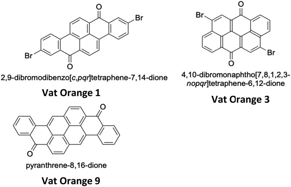 | ||
| Fig. 1 Chemical structures and the IUPAC name of the three vat dyes analyzed in this study. | ||
The rationale for investigating this group of molecules was triple fold. We deliberately intended to look into vacuum processible molecules that (i) have a large and flat π surface, a prerequisite for good charge transport; (ii) can be purified to a large extent, and (iii) can be purchased directly from the synthetic manufacturer at very low cost. Their high availability and low cost, at present time, in single digit US dollars per kilogram at several chemical manufacturers (indeed in their crude, unpurified form) permit further purification steps without increasing the final price of the highly purified (i.e. “electronic grade”) semiconductors to intangible levels. As a matter of fact, many vat dyes and pigment molecules exist in the catalog of commercially available materials for various coloring purposes (e.g. anthraquinones, acridones, quinacridones, naphthoquinones, etc.), but they are still not investigated in the organic electronics field, simply because they are not newly synthesized and reported in a fresh scientific publication by a currently active organic synthesis group. With this respect, a good example of a high volume-low cost vat dye is quinacridone, a molecule with an excellent temperature and air-stability in operating devices and a field effect mobility as high as 0.2 cm2 Vs−1, which has been demonstrated recently in our laboratory.65–67 The excellent results obtained by us with quinacridone, motivated us to look carefully into the library of long time synthesized and reported organic dyes and represented one of the main reasons to investigate the group of three anthraquinone-based vat orange dyes in this study. As a matter of fact, quinacridone can also be purchased for prices ranging from single digit to low-double digits $ per kg depending on the order volume, with the supply ability of the producers in the range of 1000 metric tons per year or more. As a comparison, modern, newly reported semiconductors, dinaphtho[2,3-b:2′,3′-f]thieno[3,2-b]thiophene (in short DNTT),21,68,69 are sold in gram amount only, for ∼$2600 per gram at Sigma-Aldrich and D18114 for ∼ $2500 per gram at 1-Material. Indeed, DNTT owns a record reported field effect mobility of 2.9 cm2 Vs−1 for highly optimized OFET device architectures,21 but many other reports place its field effect mobility below 1 cm2 Vs−1![[thin space (1/6-em)]](https://www.rsc.org/images/entities/char_2009.gif) 68,69 (the discrepancy may be due to the fact that the field effect mobility of the organic semiconductor is electric field dependent; so that the higher the applied electric field, or in other words, the higher the operating voltage that the dielectric can afford, the higher the recorded field effect mobility of the semiconductor70). Whereas the field effect mobility of DNTT is definitely not the impressive factor in a one-to-one comparison to quinacridone (i.e. ∼1 cm2 Vs−1vs. ∼0.2 cm2 Vs−1 respectively), it is ∼106 times higher price per kilogram is for sure the most remarkable one. A central motive for the low and affordable prices and the high level of supply volume of many vat dyes and pigments is definitely their ease of synthesis, that could reach reaction yield values as high as 99% even at the 1960s level industrial technology knowledge, as many of more than the 100 trans-quinacridones described in the seminal review of Labana and Labana demonstrate.71 We should remember the original promise of organic electronics, namely the advent of the low-cost era for technology, and indeed many of the dyes and pigments currently produced in large volumes and employed by the textile, cosmetics, outdoor painting, or food coloring industries, are definitely low cost-high availability materials that deserve careful investigation in the organic electronics field.
68,69 (the discrepancy may be due to the fact that the field effect mobility of the organic semiconductor is electric field dependent; so that the higher the applied electric field, or in other words, the higher the operating voltage that the dielectric can afford, the higher the recorded field effect mobility of the semiconductor70). Whereas the field effect mobility of DNTT is definitely not the impressive factor in a one-to-one comparison to quinacridone (i.e. ∼1 cm2 Vs−1vs. ∼0.2 cm2 Vs−1 respectively), it is ∼106 times higher price per kilogram is for sure the most remarkable one. A central motive for the low and affordable prices and the high level of supply volume of many vat dyes and pigments is definitely their ease of synthesis, that could reach reaction yield values as high as 99% even at the 1960s level industrial technology knowledge, as many of more than the 100 trans-quinacridones described in the seminal review of Labana and Labana demonstrate.71 We should remember the original promise of organic electronics, namely the advent of the low-cost era for technology, and indeed many of the dyes and pigments currently produced in large volumes and employed by the textile, cosmetics, outdoor painting, or food coloring industries, are definitely low cost-high availability materials that deserve careful investigation in the organic electronics field.
Experimental
The three vat dyes employed in this study were obtained directly from the synthetic factory, Shanghai Jucheng Chemicals Co. Ltd. (China), and purified two times by train sublimation, as amply described in our previous study.42Cyclic voltammetry
A one-compartment cell with the organic dye evaporated onto indium tin oxide (ITO) as described above (thickness ca. 75 nm) as the working electrode, a platinum counter electrode and an Ag/AgCl electrode as the quasi-reference electrode was used as the electrochemical cell. Cyclic voltammetry (CV) was performed using a Vertex One Ivium Potentiostat/Galvanostat inside a nitrogen (N2) flushed glove box. The electrolyte solution consisted of 0.1 M tetrabutylammonium hexafluorophosphate (TBAPF6, >99.0%, Sigma Aldrich) in dry acetonitrile (MeCN, >99.9%, Roth). The CV scans were performed at a scan rate of 20 mV s−1. Due to the dissolving of the dyes upon the electrochemical treatment, for each sample, the oxidation and reduction measurements were performed as two separate experiments always using a fresh electrode. For conversion of the applied potential versus the standard hydrogen electrode (SHE), after each measurement, a calibration with ferrocene (98%, Sigma Aldrich) was performed and the re-calculation was done according to the literature72 value of the ferrocene potential E1/2 = +0.640 V vs. SHE.Furthermore, −4.75 V was taken as the potential of SHE vs. a vacuum level, a value that is established in our laboratory and was reported previously in the literature.73,74
Spectroscopic and structural characterization
Fourier-transform infrared (FTIR) spectra of the purified powders of the three investigated Vat dyes were measured using a Bruker Vertex 80 FTIR spectrometer, equipped with a Bruker Platinum diamond attenuated total reflectance (ATR) unit. UV/Vis absorbance spectra were recorded using a PerkinElmer Lambda 1050 spectrophotometer. Photoluminescence (PL) spectra were recorded using a Photon Technology International Quanta Master 40 spectrofluorometer. The three investigated Vat dyes were measured as thin films on quartz glass, deposited by thermal evaporation. The PL spectra were measured at excitation wavelengths of 470 nm for vat orange 1, 500 nm for vat orange 3, and 460 nm for vat orange 9.OFETs fabrication
The chosen architecture of the OFET device for this study comprised a staggered bottom gate-top contact design, composed of an inorganic dielectric (aluminum oxide, AlOx, ∼16–17 nm thick) and a thin capping layer of organic dielectric (i.e. tetratetracontane, TTC). The aluminum gate electrodes (80 nm thick) were subsequently anodized for all the OFET devices fabricated in this study, by growing the aluminum oxide electrochemically via a previously reported recipe75 that was optimized over the years in our laboratories.42,76,77 The aluminum used for evaporation of the gate electrode had a purity of 99.999% (ChemPUR GmbH) and each gate electrode was evaporated at a rate of ∼4–5 nm s−1. The anodization voltage of this study was set to 10 V, producing an aluminum oxide layer of ∼16–17 nm in thickness. The aluminum oxide layer was passivated by 20 nm vacuum processed TTC (i.e. C44H90, that was annealed in situ, under vacuum at 60 °C for 1 hour) prior to the deposition of 80 nm thick vat orange semiconductor, without breaking the vacuum. Each of the three organic semiconductor vat orange dyes has been deposited at a rate of 0.1 Å s−1 without substrate heating. In line with the argument presented above relative to the number of Clar sextets identified for each of the three vat dyes investigated, indeed, the vat orange 9 showed higher thermal stability and sublimed at a temperature of ∼320–330 °C in a typical 1 × 10⁻⁶ mbar pressure of the instrument; vat orange 1 at ∼240–250 °C and vat orange 3 at ∼225–235 °C. The source and drain electrodes employed were aluminum (100 nm thick), LiF/Al (1 nm/99 nm thick) and gold (100 nm thick), respectively, for each of the three vat orange dyes, since we did not know a priori which metal contact is suitable for each semiconductor. The channel dimensions were length, L = 25 μm and width, W = 2 mm. The OFETs were measured with a probe station in a glove box, under a nitrogen atmosphere.XRD investigations and modelling
X-ray powder diffraction (XRPD) measurements were recorded at room temperature using a Bruker D8 Advance diffractometer (Bruker Co., Billerica, MA, USA) with a LYNXEYE position-sensitive detector employing Cu-Kα radiation (0.15418 nm). The data were recorded in the Bragg–Brentano (θ/2θ) horizontal geometry (flat reflection mode) between 3° and 50° in a continuous scan with a step size of 0.03° and a duration of 0.5 s seconds per step.Simulations were done by taking the single molecule mol-file from the database (Chemical Book) and using the CAS number of each molecule. Based on the given atomic point coordinates for each of the three molecules, a unit cell was built using a custom program code (js/Eclipse) by assuming monoclinic symmetry, without assuming or permitting any axis rotation. This allowed determining a 3D crystal unit containing a full set of symmetry information and atomic position in the Cartesian space point coordinates which were converted in a compatible input format for the “VESTA” free software, which finally helped us calculate the corresponding X-ray powder diffractogram presented in this study in comparison to the recorded diffractogram originating from the powder of each molecule.
Results and discussion
Motivated by the need of investigating high purity materials for electronics, we examined here a group of three industrial vat orange dyes with quinone moieties, i.e. vat orange 1 (known also as vat golden yellow RK), vat orange 3 (known also as vat brilliant orange RK) and, respectively, vat orange 9 (known as vat golden orange G), and consequently report in this article the results obtained from cyclic voltammetry, UV-Vis spectroscopy, photoluminescence, film forming characteristics, X-ray diffraction and finally charge transport performance in organic field effect transistors. The large and flat π surface of the three investigated dyes reduces the solubility in common organic solvents but does not impede their processing via physical vapor deposition. Among them, vat orange 1 and vat orange 3 either in their pristine form or as various derivatives78,79 have been so far the focus of several investigations because of their charge transport in OFETs,80–82 organic photovoltaics78,83,84 or electrochemical energy storage85 fields. A recent review article by Jean-François Morin summarizes in fact the entire effort made by the scientific community in the field of vat dye derivatization for organic electronic applications.86In the present work, we compare the above mentioned vat orange dyes that can be regarded as non-linear acenes, specifically [n,m]peri-acenoacenes,87,88 containing additionally two ketone groups. When analyzing their molecular structures, it is instructive to compare them to that of anthraquinone, which can be regarded as consisting of two benzene rings connected by two carbonyl groups. It is also helpful to regard these compounds in terms of the so-called empirical principle of Erich Clar, which links the chemical stability of a molecule to its aromaticity. In the resonance structure of aromatic compounds, a group of six π electrons arranged in a configuration resembling benzene is defined as a Clar sextet. The more of these sextets can be identified in a given aromatic compound, the more stable it should be ref. 89. Vat orange 3 can be regarded as a dibromo derivative of a binaphthyl molecule, additionally connected and stiffened by two carbonyl groups, with each naphthalene unit presenting one Clar sextet. In the case of vat orange 1, it is possible to identify an aromatic diphenyl–naphthalene structure with three Clar sextets and two additional ketone groups. The last of the examined dyes, vat orange 9, has a diphenylpyrene structure with two ketone groups, and four Clar sextets can be identified in this molecule. Thus, in the Clar approach, the studied dyes differ in their aromaticity and as a consequence in their stability.
Fig. 2 shows the photographs of the 100 nm thick films of each of the three dyes deposited for cyclic voltammetry investigations on ITO glass (panel a) and of the fabricated transistor slides. For measurement purposes, we added a droplet of silver paste on the gold source and drain pads and on the aluminum gate pads, in order to ensure better contact with the sharp measurement needles of the probe station. It is interesting to see the strikingly similar appearance of the three vat orange dyes in aggregated (powder form), with comparable shades of orange, as shown by the photograph of the evaporation crucibles, but the rather different appearance in the thin evaporated film of vat orange 3, compared to the other two investigated counterparts. As a matter of fact, vat orange 9 appears in the thin film remarkably analogous in color with vat yellow 1, reported previously by our group,80,81 a molecule that has two nitrogen atoms at its two core phenyl groups.
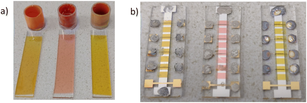 | ||
| Fig. 2 (a) Photograph of the evaporation crucibles of the vat dyes (left: orange 1, middle: orange 3 and right: orange 9) and their corresponding slides employed for the cyclic voltammetry with each material deposited as 75 nm thick layer on ITO. (b) Photograph of the OFET structure employed in this work displaying the bottom gate electrode, the patterned semiconductor (i.e. vat orange 1 in the left, vat orange 3 in the middle and vat orange 9 in the right of the photograph), and the 4 pairs of source and drain electrodes. The mask allowed also the patterning of a MIM structure (yellow electrode on the bottom of each slide shown in the photograph) necessary for the measurement of the specific capacitance of the field effect transistor. The electrode contacts were decorated with silver paste for measurement purposes. | ||
For this work, we purified the three vat orange dyes via two consecutive train sublimation methods42 and pursued a thorough material characterization of these compounds in their high purity form. We analyzed the three vat orange dyes by cyclic voltammetry (CV), photoluminescence spectroscopy (PL),90,91 UV-Vis absorption spectroscopy (UV-Vis),92 film forming by atomic force microscopy (AFM).93 We further looked into the possibility of these compounds having a useful functionality in field effect transistors.
Fig. 3 presents the cyclic voltammograms (CVs) of the investigated vat orange dyes. In all three cases, a distinct reduction peak is observed while the maximum currents of the re-oxidation peaks are faint as shown in Fig. 3(a). Vat oranges 1 and 3 show similar onset potentials of the reduction of −0.57 and −0.50 V, respectively. The reduction of vat orange 9 is cathodically shifted to −0.70 V. All three samples show similar reduction currents. It should be noted that for all three vat orange derivatives, a partial delamination of the films from the ITO/glass was observed upon reduction of the materials which may account for the significantly lower current observed for the re-oxidation peaks. The anodic CVs of the three vat orange derivatives (Fig. 3(b)) show two oxidative waves which are both irreversible. In contrast to the reductive CVs, no delamination of the films was observed upon oxidation of the materials. For all three materials, the onsets of reduction and oxidation were determined from the first reductive/oxidative waves in the CVs. The corresponding onset potentials (vs. SHE) are shown as insets in the graphs.
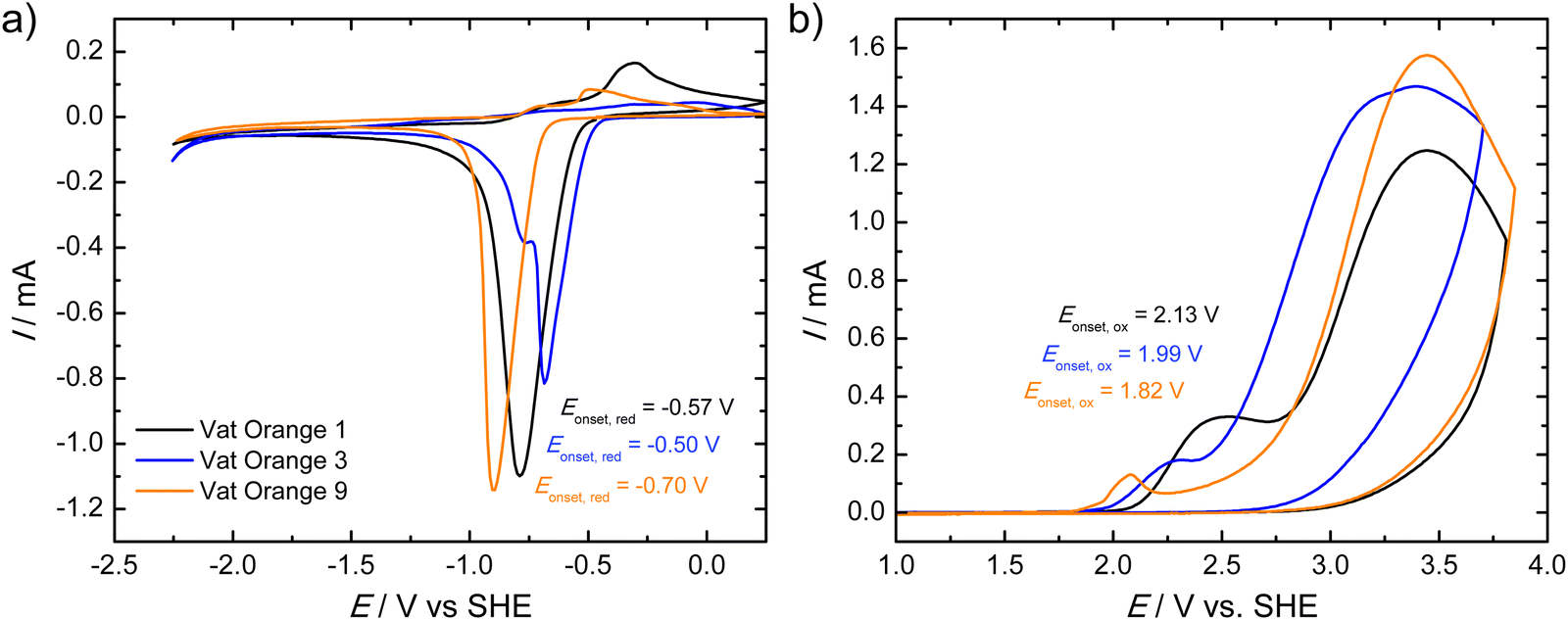 | ||
| Fig. 3 Cyclic voltammetry (CV) scans of the (a) reductions and (b) oxidations of vat orange 1 (black line), vat orange 3 (blue line) and vat orange 9 (orange line). The samples were used as thin films deposited by thermal evaporation on ITO/glass substrates. Scans were performed at a scan rate of 20 mV s−1 in a 0.1 M TBAPF6 solution in acetonitrile. | ||
For the spectroscopic characterization of the purified materials, Fourier-transform infrared (FTIR) spectra of the powders obtained from vacuum sublimation purification were measured. The spectra are displayed in Fig. 4. While the carbonyl C![[double bond, length as m-dash]](https://www.rsc.org/images/entities/char_e001.gif) O stretching vibrations for vat orange 1 (1648 cm−1) and vat orange 3 (1650 cm−1) show an almost identical spectral position, the band is shifted to 1638 cm−1 in vat orange 9. Characteristic differences between the materials can also be observed in the wavenumber regions of the aromatic CC stretching vibrations at ca. 1600–1500 cm−1 and at the aromatic C–H bending vibrations at ca. 900–680 cm−1. The patterns of the strong aromatic C–H bending peaks in this low wavenumber region can be related to the number of hydrogen atoms that are adjacent in the rings, and thus can be related to the arrangement of the fused rings in the three vat orange derivatives.94 For vat orange 1, the intense C–H bending peaks appear at slightly higher wavenumbers (777–824 cm−1) which are typical for sets of two adjacent hydrogen atoms on the rings in comparison to the sets of three adjacent hydrogen atoms in vat orange 3 occurring at lower wavenumbers (755–772 cm−1).94,95 For vat orange 9, several C–H bending peaks occur across a larger wavenumber range and can be related to the various different numbers of adjacent hydrogen atoms on the aromatic rings.
O stretching vibrations for vat orange 1 (1648 cm−1) and vat orange 3 (1650 cm−1) show an almost identical spectral position, the band is shifted to 1638 cm−1 in vat orange 9. Characteristic differences between the materials can also be observed in the wavenumber regions of the aromatic CC stretching vibrations at ca. 1600–1500 cm−1 and at the aromatic C–H bending vibrations at ca. 900–680 cm−1. The patterns of the strong aromatic C–H bending peaks in this low wavenumber region can be related to the number of hydrogen atoms that are adjacent in the rings, and thus can be related to the arrangement of the fused rings in the three vat orange derivatives.94 For vat orange 1, the intense C–H bending peaks appear at slightly higher wavenumbers (777–824 cm−1) which are typical for sets of two adjacent hydrogen atoms on the rings in comparison to the sets of three adjacent hydrogen atoms in vat orange 3 occurring at lower wavenumbers (755–772 cm−1).94,95 For vat orange 9, several C–H bending peaks occur across a larger wavenumber range and can be related to the various different numbers of adjacent hydrogen atoms on the aromatic rings.
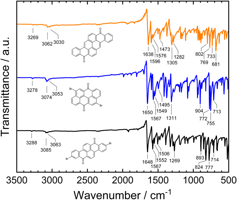 | ||
| Fig. 4 FTIR spectra of the purified powders of vat orange 1 (black), vat orange 3 (blue) and vat orange 9 (orange). The labels in the graph indicate the wavenumber positions of selected bands (in cm−1). | ||
The absorbance and photoluminescence spectra of thin films of the three vat orange derivatives on quartz glass are shown in Fig. 5.
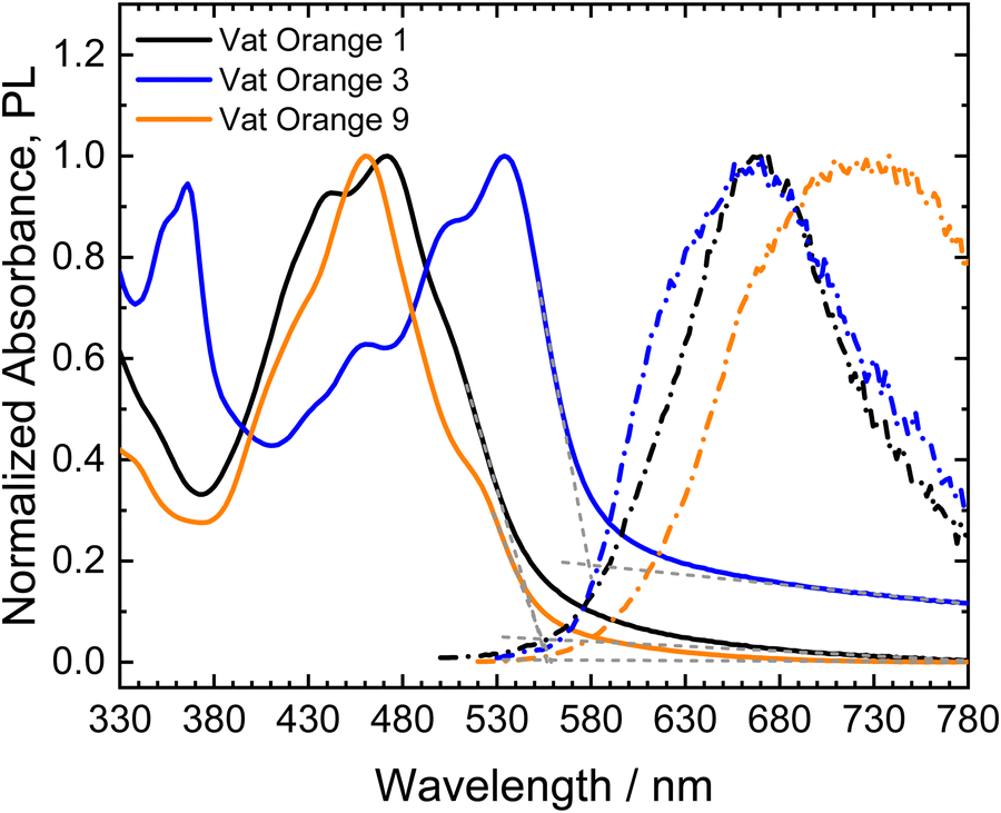 | ||
| Fig. 5 Normalized absorbance (solid lines) and PL spectra (dashed-dotted lines) of thin films of the three investigated Vat dyes deposited on quartz glass via thermal evaporation. Grey dashed lines indicate the linear fit used to determine the absorption onsets. | ||
All three materials show vibronic peak patterns in their absorption spectra, as observed for the similar molecules dibenzpyrenequinone96 and anthanthrone derivatives.97–99 For vat orange 3, the absorption maximum corresponds to the lowest energy (0–0) transition centered at 534 nm, while vat orange 1 and vat orange 9 show their absorption maxima at the second peak in the vibronic progression (0–1) at 472 nm and 460 nm, respectively. The absorption onsets of the materials were determined from linear fits of the absorption edges and baselines of the spectra, respectively. Vat orange 1 and vat orange 9 show very similar spectral positions of their absorption onsets of 553 nm (2.24 eV) and 558 nm (2.22 eV), respectively. In comparison to the other two materials, vat orange 3 shows a red-shifted absorption onset at 579 nm (2.14 eV). The above described bands are, however, hyspsochromically shifted as compared to the corresponding bands in the spectra of the linear counter parts of the studied vats with the same number of carbon atoms. The PL spectra of the investigated vat orange dyes do not show well-defined vibronic peak progressions as observed for the absorption spectra. Vat orange 1 shows its maximum PL at a spectral position of 668 nm and shows a large Stokes shift of 0.77 eV (196 nm). Vat orange 3 shows a similar emission spectrum as vat orange 1 with its emission maximum at 665 nm but with an additional higher-energy shoulder centered at 634 nm and a significantly smaller Stokes shift of the absorption and emission maxima of 0.46 eV (131 nm). For vat orange 9, the PL spectrum is very broad and strongly red-shifted with its maximum at 726 nm, resulting in an exceptionally large Stokes shift of 0.99 eV (266 nm). It should be noted that the films of all three investigated compounds showed a very low PL intensity in the measurements. The broad, featureless, low-intensity and strongly red-shifted PL may be a result of strong π–π interactions and aggregate formation of the molecules in the solid films.100–102 In the cases of vat orange 1 and vat orange 9, the higher relative intensity of the 0–1 transition in comparison to the lowest energy 0–0 transition is a further indication of the formation of H-aggregates.102,103 Furthermore, aggregation-induced phosphorescence, as was previously reported for anthraquinone derivatives,104 should be considered as a possible process, due to the typically high efficiencies of intersystem crossing (ISC) found in carbonyl-containing chromophores like anthanthrone derivatives.98,99 Intersystem crossing is further promoted by the substitution of the molecules with heavy atoms such as bromide99 as in vat orange 1 and vat orange 3.
Table 1 shows a summary of the absorption onsets (corresponding to the optical bandgap energies, Eg,opt), the ionization potential (IP) and the electron affinity (EA) values as well as the electrochemical bandgaps, Eg,CV, as determined from the reduction and oxidation onset potentials (see Fig. 3) after expressing the onset potential on the absolute potential scale and its multiplication with the elementary charge. The electrochemical bandgap energies show a similar trend as the optical bandgap energies with vat orange 1 showing the highest value, followed by vat orange 9 and finally vat orange 3. For all three materials, however, the electrochemical bandgap energies are higher than the optical ones. This is frequently observed in the comparison of electrochemical and optical bandgaps.105 The differences in the optical and electrochemical bandgap values may be related to an influence of the exciton binding energy in the materials, interfacial resistances, ion solvation and coulombic effects.106,107
| Material | ΔEg,opt/eV | E onset, red/V | EA/eV | E onset, ox/V | IP/eV | ΔEg,CV/eV |
|---|---|---|---|---|---|---|
| Vat Orange 1 | 2.24 | −0.57 | 3.59 | 2.13 | 6.29 | 2.70 |
| Vat Orange 3 | 2.14 | −0.50 | 3.66 | 1.99 | 6.15 | 2.49 |
| Vat Orange 9 | 2.22 | −0.70 | 3.46 | 1.82 | 5.98 | 2.52 |
Atomic force microscopy images of 80 nm thick layers of each of the vat orange dyes are shown in Fig. 6. The vat oranges 1 and 9 grow in a similar pattern of small grains coalesced together into larger grain domains. Vat orange 3 however has a peculiar growth pattern, showing the initial small grains aggregating in distinct ribbons, that are more clearly visible in thinner films, but nevertheless evident also in the 80 nm thick film shown in Fig. 6. The surface roughness of the three films is comparable, with the root mean square value (rms) of vat orange 1 in the range of 12 nm, of vat orange 3 in the range of 15 nm and vat orange 9 in the range of 20 nm respectively.
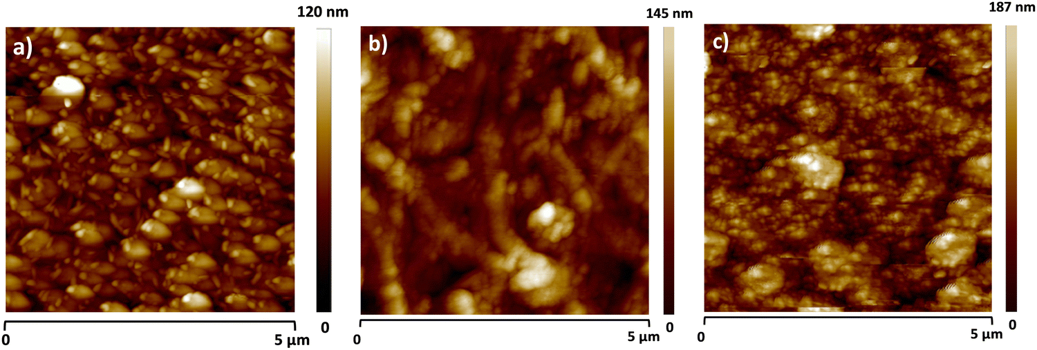 | ||
| Fig. 6 Atomic force microscopy (AFM) images of 80 nm deposited thick film of the vat orange dyes: (a) vat orange 1 (rms ∼ 12.5 nm), (b) vat orange 3 (rms ∼ 15.1 nm) and (c) vat orange 9 (rms ∼ 20.4 nm). | ||
OFETs have been fabricated with the three orange dyes, following the procedure detailed in the Experimental section. Since we did not know a priori what type of conduction mechanism these dyes have preponderantly (i.e. either p-type, or n-type, or ambipolar), we proceeded and contacted them with a large variety of metal electrodes: silver, aluminum, lithium fluoride + aluminum and gold, respectively. Given the particular design of our mask that allows the patterning of 8 individual patches of the organic semiconductor on the gate dielectric, we could deposit in one run half of these patches with one type of metal contact (as it is visible in Fig. 2) and could deposit the remaining half of the semiconductor patches on the same slide, with a different type of metal contact, with the aid of a different positional source-drain mask. With this respect, we observed that depositing aluminum directly on the two brominated vat orange dyes (orange 1 and 3, respectively) resulted in the occurrence of black source and drain contacts of very poor conductivity, irrespective of the rate of deposition of aluminum (varied from 0.1 Å s−1 to 10 Å s−1, and regardless of either keeping the rate constant or ramping it up during the entire evaporation). However, aluminum deposited as expected, in a shiny metallic film on vat orange 9, which let us infer that aluminum reacted violently with the bromine moieties of the two orange dyes, i.e. vat orange 1 and 3 respectively. Masking the aluminum layer with a thin lithium fluoride of ∼1 nm in thickness helped mitigate this event and produced electrodes that could be eventually interrogated under the probe station. Silver metal did not produce such an evident reaction with the two brominated dyes, but nevertheless, the OFET performance of all three vat orange dyes capped by silver was inferior to the respective one of the lithium fluoride + aluminum or gold electrodes. Interestingly, as Fig. 7 shows, each vat orange dye has a preference for one particular metal for source and drain contacts. Moreover, they are all n-type semiconductors, even when contacted with gold as it is visible in the case of vat oranges 3 and 9, and all the devices display minimal hysteresis, which being counterclockwise for the n-type semiconductors can be attributed to the shallow surface traps originated at the interface of the organic dielectric to the organic semiconductor.108–110 Vat orange 1 also worked with gold as a source and drain electrodes; however, the recorded field effect mobility was slightly below the one recorded with LiF/Al electrodes, and we decided to show the latter device here, in order to prove the point that LiF/Al works well also for all the three dyes. In addition to LiF/Al, vat orange 1 showed similar performance with silver electrodes (data not shown). In the case of vat orange 3, however, as we reported already in our previous publications dealing with this organic semiconductor,80,81 gold is definitely the metal of choice for the source and drain contacts of this particular dye. A preference of gold versus other dedicated metals (i.e. pure aluminum or pure silver) as contacts for an n-type semiconductor is rather bizarre, and current efforts in our group are aimed precisely to help clarifying this issue. Vat orange 1 displayed also a superlinear increase at moderately negative gate voltages in the output characteristic (see Fig. 7b)), implying that the semiconductor is actually ambipolar. Nevertheless, LiF/Al electrodes did not allow for the appropriate charge injection and the occurrence of the p-type channel when measured in the negative gate regime in the transfer characteristic. The devices with gold showed modest current as p-type (hole) transport, with maximum Ids below 1 nA. We conclude therefore that is safe at this point to call all three vat orange dyes investigated here as n-type semiconductors only with field effect mobilities of ∼1 × 10⁻⁴ cm2 Vs−1 for vat orange 1, ∼6 × 10⁻⁴ cm2 Vs−1 for vat orange 3, and a more modest 2 × 10⁻⁶ cm2 Vs−1 for vat orange 9, as Fig. 7 shows. It is worth mentioning that the best values of the field effect mobilities for the vat orange 3, i.e. ∼2 × 10⁻³ cm2 Vs−1 reported in our previous publications80,81 were obtained with the respective semiconductor deposited on an adenine capping layer of the aluminum oxide dielectric, and represented values obtained for highly optimized devices obtained for the organic semiconductor deposited on a dedicated evaporator for itself only over a period of time of several weeks. As we previously reported in our previous publication dealing with the importance of materials purity for the success of organic electronics field,42 this event if not of a negligible influence. The study reported here, however, had TTC as a capping layer of the aluminum oxide dielectric, and was a much faster work involving the fabrication of 4 batches only of devices for each of the 4 organic semiconductors, with each batch dedicated to one type of metal contact (Al, Ag, Au and LiF/Al). Each particular batch comprised 6 glass slides with 8 OFET devices per slide (as it is shown in Fig. 2), i.e. 48 OFETs in total for each type of metal contact and each of the 3 dyes. Obviously, the result obtained here, ∼6 × 10⁻⁴ cm2 Vs−1 is not far off the value obtained previously for vat orange 3, i.e. ∼2 × 10⁻³ cm2 Vs−181 and demonstrates that the fabrication route for this organic semiconductor is quite reproducible on different dielectric substrates.
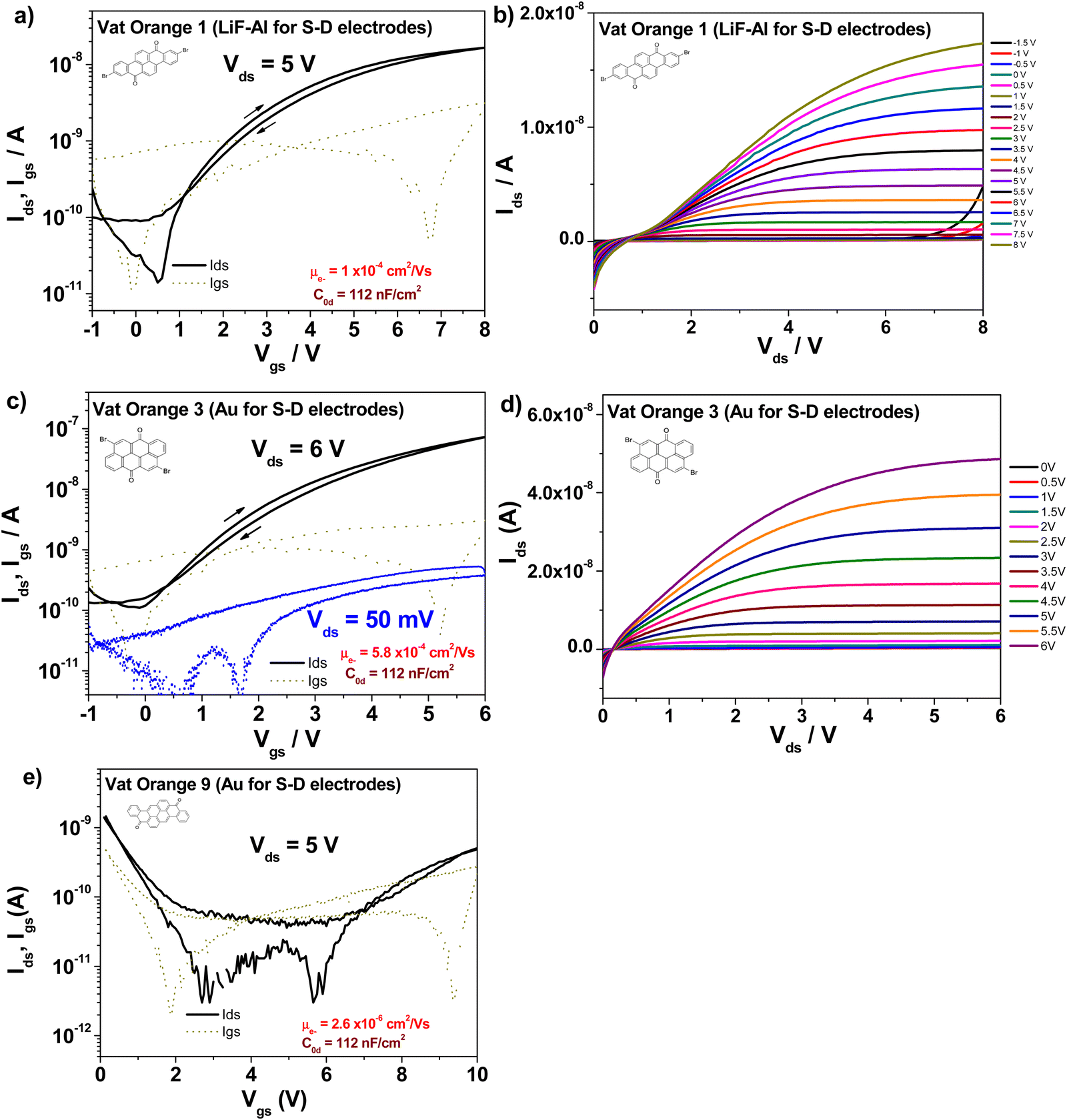 | ||
| Fig. 7 Transfer and output characteristics of the OFET devices with vat orange dyes. The contact electrodes are listed as inset in the graphs, together with the values of the specific capacitances of the combo dielectric of ∼16 nm Aluminum oxide and 20 nm TTC, and the calculated values of the field effect mobilities. The output characteristic of vat orange 9 was severely influenced by the leakage current of the device and is not shown here. (a) Transfer and (b) output characteristics of vat orange 1; (c) transfer and (d) output characteristics of vat orange 3; (e) transfer characteristics of vat orange 9. | ||
The figures of merit of the fabricated devices, i.e. field effect mobility, threshold voltage, subthreshold swing and on/off ratio, respectively, are displayed in Table 2.
| OFET structure (Gate-Dielectric-Semiconductor-Source/Drain) | Specific capacitance (nF cm−2) | Field effect mobility-electron channel -(cm2 Vs−1) | Threshold voltage (V) | Subthreshold swing (mV dec−1) | On/Off ratio |
|---|---|---|---|---|---|
| Al – AlOx + TTC – Vat orange 1-LiF + Al | 112 | 1 × 10⁻⁴ | 0.1 | 338 | 1.8 × 10² |
| Al – AlOx + TTC – Vat orange 3-Au | 112 | 5.8 × 10⁻⁴ | 0.25 | 1135 | 5.4 × 10² |
| Al – AlOx + TTC – Vat orange 9-Au | 112 | 2.6 × 10⁻⁶ | 4.8 | 4120 | 38 |
What is interesting to observe is that is vat orange 9 analyzed in this study produced far more modest results than the structurally related vat yellow 1 semiconductor reported by us in a previous study, for which a field effect mobility of 1.2 × 10⁻² cm2 Vs−1 was recorded on many fabricated devices in our laboratory employing a similar fabrication recipe and the same instruments.80,81 In addition, vat orange 9 performance in OFETs is significantly more modest than that of the other two anthraquinone derivatives investigated in the present study, as shown in Fig. 7 and Table 2 clearly. We intended to find the answer to this performance discrepancy between the brominated and the non-brominated vat dyes explored in this study through X-ray diffraction and match further our experimental findings with simulated data (as explained in the Experimental section). For vat orange 1 (C24H10Br2O2) (see Fig. 8), we simulated the powder diffraction reflections and (hkl)-values and compared them to the measured distinct spectral features. Simulations are done by taking the single molecule mol-file from the database (Chemical Book: CAS No. 1324-11-4). It should be noted that under the same sum formula, two isomers may exist (see also: PubChem CID 73989). Here, we used the one with the two Br-atoms bonding at the very opposite sides of the two benzene rings as schematically presented in Fig. 1. Based on the given atomic point coordinates for this molecule, a unit cell was built using a custom program code (js/Eclipse) by assuming monoclinic symmetry and space group P21/n (int. 14). Here, no rotation axis was permitted or assumed. This allows for determination of a 3D crystal unit containing a full set of symmetry information and atomic positions in Cartesian space point coordinates which were converted into a compatible input format for the “VESTA” free software, which finally calculated the corresponding X-ray powder diffractogram presented in Fig. 8(a). In Fig. 8(b), the powder diffractogram of a thin layer of vat orange 1 is presented which was first deposited on glass by vacuum evaporation and then removed from the substrate. The powder collected from the deposited thin film of vat orange 1 displays less crystallinity than the precursor powder, as shown by the comparison of the XRPD recording in the two panels of Fig. 8. We should mention that the attempt to model the diffraction peaks of the isomer of vat orange 1 having both Br atoms bond to the same benzene ring provided a fully off XRPD spectra that did not match at all the recorded one stemming from the powder. This fact was indicative to us that the powder we analyzed and worked with in this study was composed of the isomer displayed in Fig. 1.
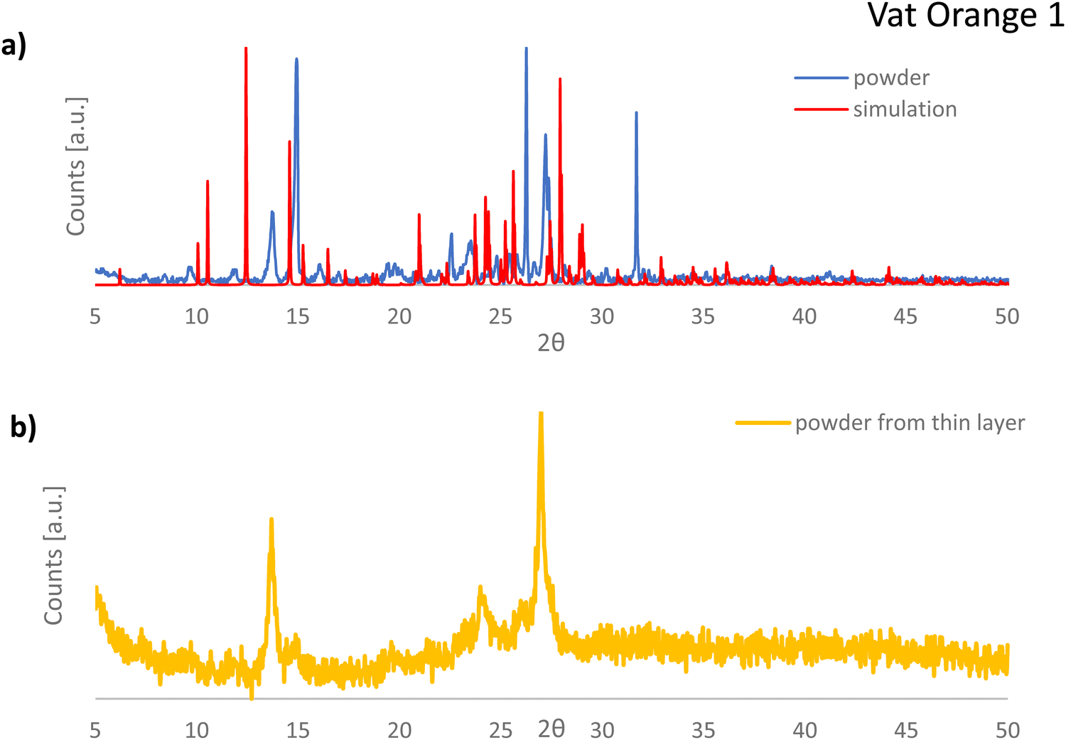 | ||
| Fig. 8 (a) Comparison of the recorded data for vat orange 1 powder (blue line) and simulation of the crystal reflections obtained with Vesta software (red line); (b) The XRPD data of vat orange 1 deposited as a thin layer on glass via vacuum sublimation and scratched from the glass prior to the investigation. | ||
Moreover, it should be mentioned that: (1) the modelling data provided more diffraction peaks than the experimentally recorded XRPD spectrum (see Fig. 8) and (2) the recorded peaks from the powder measurement that match the simulation data are offset to some fractions of a degree compared to their ideal position predicted by simulation. This event is well known in crystallography when dealing with very small, micrometer size crystals, that are inherently strained, with their built-in strain induced by the growth process on the substrate during vacuum deposition.
The crystal structure representation of vat orange 1 is presented in Fig. 9, with the associated view from each of the three-coordinate axes.
 | ||
| Fig. 9 Crystal structure of vat orange 1, with the view from (a) a-axis, (b) b-axis and (c) c-axis. | ||
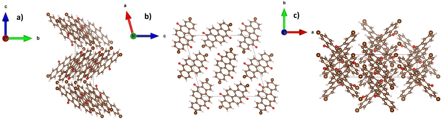
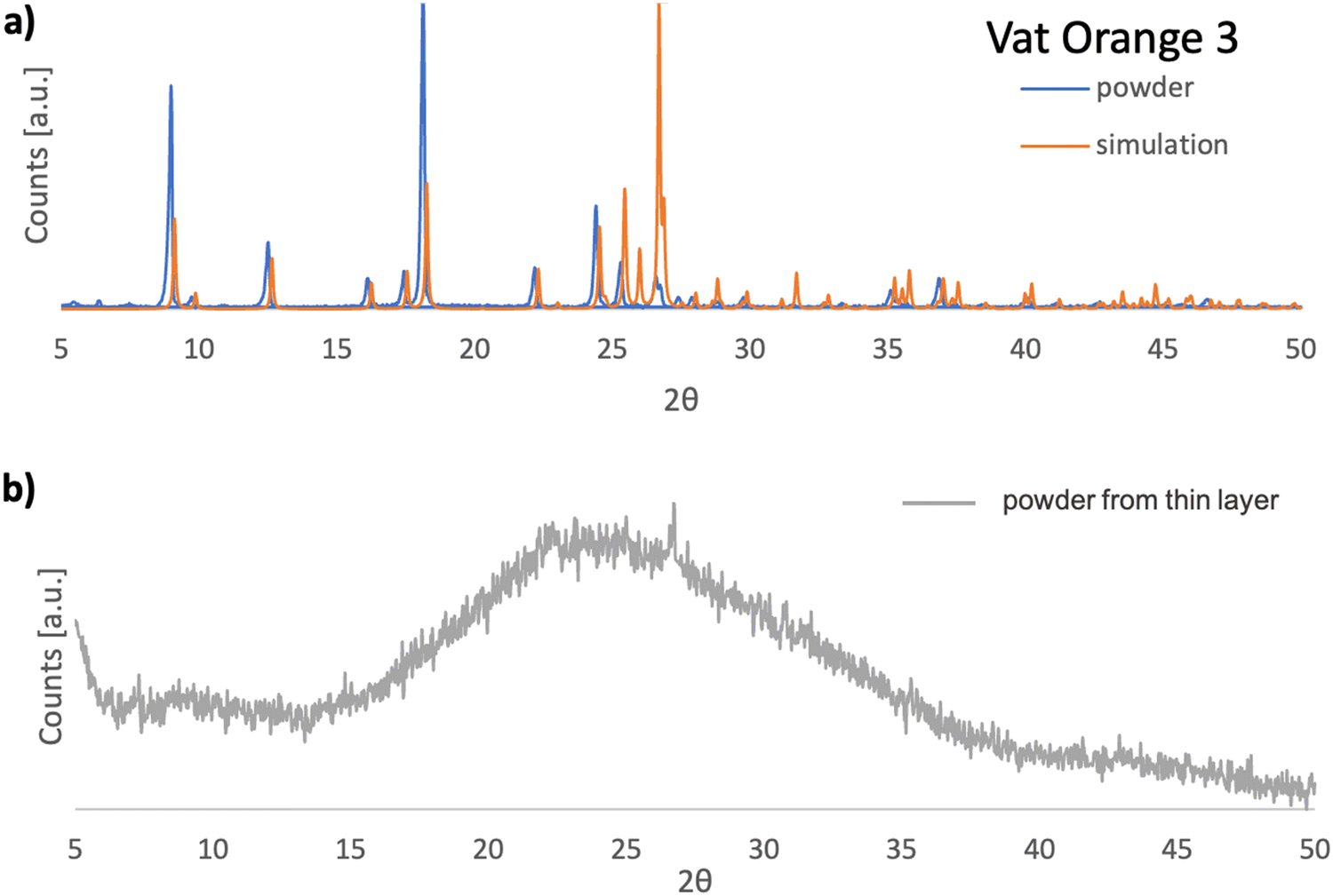
In Fig. 10(a), the XRPD pattern of vat orange 3 is presented and compared to the corresponding pattern obtained by simulation of the single crystal data reported in the literature.111 A very good match of the registered reflections in terms of their position and relative intensity between the powdered sample and the powder diffractogram simulated based on the single crystal data is evident. This indicates that the investigated dye in its powder form has the same crystalline structure as that reported for the single crystal (monoclinic P21/c).111Fig. 10(b) presents the powder diffractogram of the vat orange 3 which was first deposited as a thin film on glass by vacuum evaporation and then removed from the substrate. It is evident that the deposited film of vat orange 3 is essentially amorphous since only a broad amorphous halo can be seen without the presence of sharp Bragg reflections.
 | ||
| Fig. 10 (a) Comparison of the recorded data for vat orange 3, powder (blue line) and simulation of the crystal reflections obtained with Vesta software (orange line); (b) the XRPD data of vat orange 3 deposited as a thin layer on glass via vacuum sublimation and scratched from the glass prior to the investigation. | ||
In a similar observation to the recorded peaks of vat orange 1, also the recorded peaks of vat orange 3 that match the simulation data are visibly offset to some fractions of a degree compared to their ideal position predicted by simulation, a fact most likely attributed to the built-in strain in the crystal induced by the growing process on a glass substrate. The crystal structure representation of vat orange 3 is presented in Fig. 11, with the associated view from each of the coordinate axes presented in individual panels.
 | ||
| Fig. 11 Crystal structure of vat orange 3, with the view from (a) a-axis, (b) b-axis and (c) c-axis. | ||
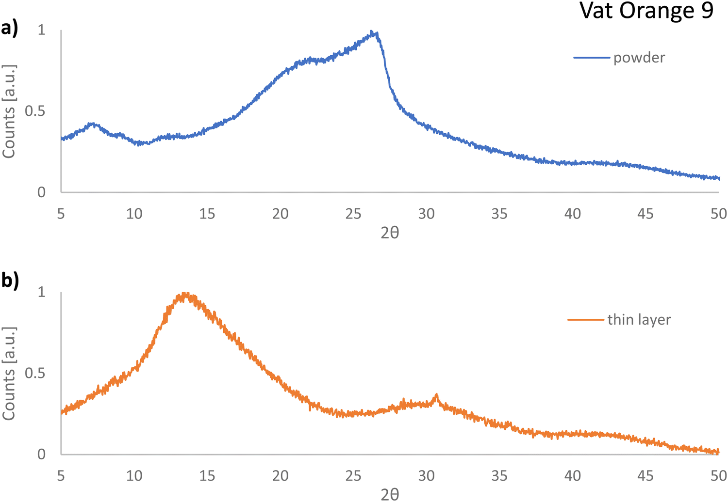
In contrast to our expectations and in full contrast to the cases of vat orange 1 and vat orange 3, the powder of vat orange 9 investigated in this study displayed fully amorphous XRPD recordings (see Fig. 12(a)). Moreover, the diffractogram recorded for the film first deposited on glass via vacuum sublimation and then removed from the glass also shows features characteristic of the amorphous state (Fig. 12(b)). It should be noted that vat orange 9 should be in fact capable of crystallization, since its crystal structure was reported to have the P21/n space group,112 however it seems plausible to conclude that our processing conditions did not allow this molecule to deposit and grow in a crystalline layer. Interestingly, both analyzed powders of vat orange 9 were amorphous, i.e. the one stemming from the purification by train-sublimation method and the one coming after its vacuum deposition on a glass substrate, an event that may help explain the low performance of this dye when employed as a semiconductor in OFETs.
 | ||
| Fig. 12 (a) The XRPD recorded data for vat orange 9 from precursor powder; and (b) the XRPD data of vat orange 9 deposited as a thin layer on glass via vacuum deposition and scratched from the glass prior to the investigation. | ||
The lattice parameters of vat orange 1 and 3 as determined by the Vesta software are presented in Table 3
| Material | Lattice system | Space group | Lattice parameters | Unit cell volume (Å3) | |||||
|---|---|---|---|---|---|---|---|---|---|
| a (Å) | B (Å) | C (Å) | α (°) | β (°) | γ (°) | ||||
| Vat orange 1 | Monoclinic | P21/n | 17.435 | 4.871 | 18.263 | 90.000 | 105.857 | 90.000 | 1492.194 |
| Vat orange 3 | Monoclinic | P21/c | 3.865 | 19.424 | 10.113 | 90.000 | 92.560 | 90.000 | 758.463 |
Our study shows that it is plausible to conclude that the molecular parameters of the studied compounds play a significant role in determining the performance of OFETs. Analysis of the data collected in Table 1 leads to a clear conclusion that the test transistor characteristics improve with increasing electron affinity (EA) of the used organic semiconductors; however, the crystallinity of the deposited molecules plays an integral role in the final performance too, as the XRPD study clearly demonstrates. This reasoning can be extended to the comparison of the performance of vat yellow 1 and vat orange 9-based OFETs, two molecules with very similar chemical structures. Substitution of two carbon atoms with more electronegative nitrogen ones in vat yellow 1 (flavanthrone) inevitably leads to an increase in its EA as compared to the case of vat orange 9. As a result, in vat yellow1-based OFETs, the charge injection barrier is lowered and the charge carrier's mobility improved.
Conclusions
We studied three commercially available vat orange dyes that are produced in large volume for the synthetic textile coloring industry. After their purification, we performed a thorough material characterization of the three small molecules and followed it with the fabrication of organic field effect transistors. Although the recorded field effect mobilities are indeed not impressive in their absolute value compared to state-of-the-art semiconductors in the field113–115 and can definitely not contribute in their unmodified form in reaching the coveted goal of gigahertz frequency in organic electronic circuits,10 these three commercially available vat dyes are n-type semiconductors of very good stability to degradation (oxidation) when stored in air. With this respect, we observed a very nice reproducibility of the OFET results fabricated several years apart, in an identical configuration and using an identical procedure, having the three purified vat dyes explored in this study stored in a laboratory sample box in air. Due to the low lying LUMO level of these molecules that is lower than −4.0 eV, these n-type semiconductors cannot be measured in ambient air, a fact possible for other air-stable n-type molecules.116–118 However, the two brominated dyes, vat orange 1 and orange 3, are easy to manipulate at their molecular level because of them possessing highly reactive bromine moieties.79,84 Therefore, we envision ample possibilities to chemically modify these two brominated vat orange dyes and synthesize various polymeric networks, either linear or branched. The recording of n-type and not p-type charge transport with gold contact electrodes in OFETs with these vat dyes needs definitely further attention. Possibly metals that can afford injecting into the deep HOMO level of these molecules like for example palladium may allow for the recording of hole transport in these organic semiconductors. Nevertheless, their low cost and their immense availability directly at the chemical producers or at the high-volume chemical retailers nearby the production facilities, represent good arguments to invest further work into the chemical modification of these dyes for particular applications. Alongside the choice of precursor materials, the green synthetic route, the performance and stability in operation of the designed product together with its biodegradability, biocompatibility, even recyclability characteristics,119 the cost and efficiency of the synthesis and the affordability of the final product are definitely key parameters to consider in order to reach sustainability in electronics.120Conflicts of interest
There are no conflicts to declare.Acknowledgements
Financial support from the project “EINSTEIN”, grant no. 101136377 (HORIZON-WIDERA-2023-ACCESS-03) is gratefully acknowledged. Kamil Kotwica acknowledges financial support from the National Science Centre of Poland, grant no. 2019/32/C/ST5/00179. Felix Mayr gratefully acknowledges financial support from the Austrian Research Promotion Agency (FFG) (Plas-Ion-Photo Kat, Grant No. 888408). We gratefully acknowledge the Wittgenstein Prize of the Austrian Foundation of Advancement of Science (FWF) for Prof. Serdar Sariciftci (Project Number Z 222-N19).References
- G. Horowitz, D. Fichou, X. Peng, Z. Xu and F. Garnier, A field-effect transistor based on conjugated alpha-sexithienyl, Solid State Commun., 1989, 72(4), 381–384 CrossRef CAS.
- G. Horowitz, Organic thin film transistors: From theory to real devices, J. Mater. Res., 2004, 19(7), 1946–1962 CrossRef CAS.
- G. Horowitz, Organic field-effect transistors, Adv. Mater., 2008, 10(5), 365–377 CrossRef.
- D. Braga and G. Horowitz, High-performance organic field-effect transistors, Adv. Mater., 2009, 21(14–15), 1473–1486 CrossRef CAS.
- L. Kergoat, L. Herlogsson, D. Braga, B. Piro, M. C. Pham, X. Crispin, M. Berggren and G. Horowitz, A water-gate organic field-effect transistor, Adv. Mater., 2010, 22(23), 2565–2569 CrossRef CAS PubMed.
- K. R. Sarma, in Flexible Displays: Attributes, Technologies Compatible with Flexible Substrates, and Applications, ed. J. Chen, W. Cranton, M. Fihn, Handbook of Visual Display Technology, Springer, Cham, 2016 DOI:10.1007/978-3-319-14346-0_61.
- Z. Zhao, K. Liu, Y. Liu, Y. Guo and Y. Liu, Intrinsically flexible displays: key materials and devices, Natl. Sci. Rev., 2022, 9, nwac090 CrossRef CAS PubMed.
- C. J. Brabec, N. S. Sariciftci and J. C. Hummelen, Plastic solar cells, Adv. Funct. Mater., 2001, 11(1), 15–26 CrossRef CAS.
- B. Stadlober, M. Zirkl and M. Irimia-Vladu, The Route towards Sustainable Smart Sensors: Ferroelectric PVDF-based Materials and Their Integration into Flexible Electronics, Chem. Soc. Rev., 2019, 48, 1787–1825 RSC.
- H. Klauk, Will We See Gigahertz Organic Transistors?, Adv. Electron. Mater., 2018, 4(10), 1700474 CrossRef.
- T. Leydecker, Z. M. Wang, F. Torricelli and E. Orgiu, Organic-based inverters: basic concepts, materials, novel architectures and applications, Chem. Soc. Rev., 2020, 49, 7627–7670 RSC.
- I. Singh, M. Kumar, J. Kaur and H. Y. Aboul-Enein, Versatility of Radio Frequency Identification (RFID) Tags in the Pharmaceutical Industry, Instrum. Sci. Technol., 2008, 36(6), 656–663 CrossRef CAS.
- M. B. Ahmad and F. Alkasim Nababa, The Need of Using a Radio Frequency Identification (RFID) System, Int. J. New Comput. Archit. Appl., 2021, 11(2), 22–29 Search PubMed.
- D. J. Lipomi and Z. Bao, Stretchable and Ultraflexible Organic Electronics, MRS Bull., 2017, 42, 93–97, DOI:10.1557/mrs.2016.325.
- X.-H. Zhang, B. Domercq and B. Kippelen, High-performance and Electrically Stable C60 Organic Field-effect Transistors, Appl. Phys. Lett., 2007, 91, 092114 CrossRef.
- K. Liu, B. Ouyang, X. Guo, Y. Guo and Y. Liu, Advances in flexible organic field-effect transistors and their applications for flexible electronics, npj Flexible Electron., 2022, 6, 1 CrossRef CAS.
- C. W. Sele, T. von Werne, R. H. Friend and H. Sirringhaus, Lithography-Free, Self-Aligned Inkjet Printing with Sub-Hundred-Nanometer Resolution, Adv. Mat., 2005, 17, 997–1001 CrossRef CAS.
- J. A. Rogers, Z. Bao, H. E. Katz and A. Dodabalapur, Thin-Film Transistors, Marcel Dekker Inc., New York, 2003, pp. 377–425 Search PubMed.
- F. Wu, Y. Liu, J. Zhang, S. Duan, D. Ji and H. Yang, Recent Advances in High-Mobility and High-Stretchability Organic Field-Effect Transistors: From Materials, Devices to Applications, Small Methods, 2021, 5, 2100676 CrossRef CAS PubMed.
- K. J. Lee, M. J. Motala, M. A. Meitl, W. R. Childs, E. Menard, A. K. Shim, J. A. Rogers and R. G. Nuzzo, Large-Area, Selective Transfer of Microstructured Silicon: A Printing- Based Approach to High-Performance Thin-Film Transistors Supported on Flexible Substrates, Adv. Mat., 2005, 17, 2232–2236 Search PubMed.
- T. Yamamoto and Kazuo Takimiya, Facile Synthesis of Highly π-Extended Heteroarenes, Dinaphtho[2,3-b:2′,3′-f]chalcogenopheno[3,2-b]chalcogenophenes, and their Application to Field-Effect Transistors, J. Am. Chem. Soc., 2007, 129(8), 2224–2225 CrossRef CAS PubMed.
- A. Facchetti, π-Conjugated polymers for organic electronics and photovoltaic cell applications, Chem. Mater., 2011, 23(3), 733–758 CrossRef CAS.
- A. Kovalenko, C. Yumusak, P. Heinrichova, S. Stritesky, L. Fekete, M. Vala, M. Weiter, N. S. Sariciftci and J. Krajcovic, Adamantane substitutions: a path to high-performing, soluble, versatile and sustainable organic semiconducting materials, J. Mater. Chem. C, 2017, 5, 4716–4723 RSC.
- M. Kratochvil, M. Ciganek, C. Yumusak, H. Seelajaroen, I. Cisarova, J. Fabry, M. Vala, S. Lunak, M. Weiter, N. S. Sariciftci and J. Krajcovic, Near-infrared absorbing hydrogen-bonded dithioketopyrrolopyrrole (DTPP) n-type semiconductors, Dyes Pigm., 2022, 197, 109884 CrossRef CAS.
- H. Usta, C. Risko, Z. Wang, H. Huang, M. K. Deliomeroglu, A. Zhukhovitskiy, A. Facchetti and T. J. Marks, Design, Synthesis, and Characterization of Ladder-Type Molecules and Polymers. Air-Stable, Solution-Processable n-Channel and Ambipolar Semiconductors for Thin-Film Transistors via Experiment and Theory, J. Am. Chem. Soc., 2009, 131(15), 5586–5608 CrossRef CAS PubMed.
- M. Goel, C. D. Heinrich, G. Krauss and M. Thelakkat, Principles of Structural Design of Conjugated Polymers Showing Excellent Charge Transport toward Thermoelectrics and Bioelectronics Applications, Macromol. Rapid Commun., 2019, 40, 1800915 CrossRef PubMed.
- Z. Bao, J. A. Rogers and H. E. Katz, Printable Organic and Polymeric Semiconducting Materials and Devices, J. Mater. Chem., 1999, 9, 1895–1904 RSC.
- F. Mathies, H. Eggers, B. S. Richards, G. Hernandez-Sosa, U. Lemmer and U. W. Paetzold, Inkjet-printed triple cation perovskite solar cells, ACS Appl. Energ. Mater., 2018, 1(5), 1834–1839 CrossRef CAS.
- S. G. Bucella, A. Luzio, E. Gann, L. Thomsen, C. R. McNeill, G. Pace, A. Perinot, Z. Chen, A. Facchetti and M. Caironi, Macroscopic and high-throughput printing of aligned nanostructured polymer semiconductors for MHz large-area electronics, Nat. Commun., 2015, 6(1), 8394 CrossRef CAS PubMed.
- M. Kaltenbrunner, T. Sekitani, J. Reeder, T. Yokota, K. Kuribara, T. Tokuhara, M. Drack, R. Schwödiauer, I. Graz, S. Bauer-Gogonea, S. Bauer and T. Someya, An Ultra-Lightweight Design for Imperceptible Plastic Electronics, Nature, 2013, 499, 458–463 CrossRef CAS PubMed.
- C. J. Bettinger, R. Langer and J. T. Borenstein, Engineering Substrate Topography at the Micro-And Nanoscale to Control Cell Function, Angew. Chem., Int. Ed., 2009, 48(30), 5406–5415 CrossRef CAS PubMed.
- A. Camus, M. Reali and C. Santato, Advances in high-resolution printed transistors: The case of bio-sourced organic materials, Curr. Opin. Green Sustainable Chem., 2022, 34, 100594 CrossRef CAS.
- M. Irimia-Vladu, E. D. Glowacki, N. S. Sariciftci and S. Bauer, Green materials for electronics, John Wiley & Sons, Weinheim, 2017 Search PubMed.
- K. Walzer, B. Maennig, M. Pfeiffer and K. Leo, Highly efficient organic devices based on electrically doped transport layers, Chem. Rev., 2007, 107(4), 1233–1271 CrossRef CAS PubMed.
- Organic Photovoltaics: Materials, Device Physics, and Manufacturing Technologies, ed C. Brabec, U. Scherf, V. Dyakonov, Wiley, 2011 Search PubMed.
- Alan J. Heeger, Niyazi Serdar Sariciftci and Ebinazar B. Namdas, Semiconducting and metallic polymers, Oxford University Press, 2010 Search PubMed.
- Y. Mei, A. L. Diao, L. Appleton, T. Fang and Z. Bao, Integrated Materials Design of Organic Semiconductors for Field-Effect Transistors, J. Am. Chem. Soc., 2013, 135, 6724–6746 CrossRef PubMed.
- M. Leitgeb, D. Nees, S. Ruttloff, U. Palfinger, J. Götz, R. Liska, M. R. Belegratis and B. Stadlober, Multilength scale patterning of functional layers by roll-to-roll ultraviolet-light-assisted nanoimprint lithography, ACS Nano, 2016, 10(5), 4926–4941 CrossRef CAS PubMed.
- N. Graff and D. Djurdjanovic, Modelling, Simulation and Control of Roll-to-Roll Physical Vapor Deposition Processes, Procedia CIRP, 2022, 113, 546–551 CrossRef.
- D. M. Taylor, Vacuum-Thermal-Evaporation: The Route for Roll-To-Roll Production of Large-Area Organic Electronic Circuits, Semicond. Sci. Technol., 2015, 30, 054002 CrossRef.
- M. Irimia-Vladu, N. Marjanovic, M. Bodea, G. Hernandez-Sosa, A. Montaigne Ramil, R. Schwödiauer, S. Bauer, N. S. Sariciftci and F. Nüesch, Small-molecule Vacuum Processed Melamine- C60, Organic Field-Effect Transistors, Org. Electron., 2009, 10(3), 408–415 CrossRef CAS.
- C. Yumusak, N. S. Sariciftci and M. Irimia-Vladu, Purity of Organic Semiconductors as a Key Factor for the Performance of Organic Electronic Devices, Mater. Chem. Front., 2020, 4, 3678–3689 RSC.
- C. K. Chiang, C. R. Fincher Jr., Y. W. Park, A. J. Heeger, H. Shirakawa and E. J. Louis, Electrical Conductivity in Doped Polyacethylene, Phys. Rev. Lett., 1977, 39, 1098–1101 CrossRef CAS.
- C. P. Jarrett, R. H. Friend, A. R. Brown and D. M. de Leeuw, Field Effect Measurements in Doped Conjugated Polymer Films: Assessment of Charge Charrier Mobilities, J. Appl. Phys., 1995, 77, 6289 CrossRef CAS.
- M. Irimia-Vladu and J. W. Fergus, Impedance spectroscopy of Thin Films of Emeraldine Base Polyaniline and its Implications for Chemical Sensing, Synth. Met., 2006, 156(21–24), 1396–1400 CrossRef CAS.
- M. Egginger, M. Irimia-Vladu, R. Schwödiauer, A. Tanda, I. Frischauf, S. Bauer and N. S. Sariciftci, Mobile Ionic Impurities in Poly(vinyl alcohol) Gate Dielectric: Possible Source of Hysteresis in Organic Field-effect Transistors, Adv. Mater., 2008, 20, 1018–1022 CrossRef CAS.
- L. S. McCarty and G. M. Whitesides, Electrostatic Charging Due to Separation of Ions at Interfaces: Contact Electrification of Ionic Electrets, Angew. Chem., Int. Ed., 2008, 47(12), 2188–2207 CrossRef CAS PubMed.
- R. J. Klein, S. Zhang, S. Dou and B. H. Jones, Modelling Electrode Polarization in Dielectric Spectroscopy: Ion Mobility and Mobile Ion Concentration of Single-ion Polymer Electrolytes, J. Chem. Phys., 2006, 124, 144903 CrossRef PubMed.
- M. Egginger, S. Bauer, R. Schwödiauer, H. Neugebauer and N. S. Sariciftci, Current versus gate voltage hysteresis in organic field effect transistors, Monatsh. Chem., 2009, 140, 735–750 CrossRef CAS.
- M. Egginger, M. Irimia-Vladu, R. Schwödiauer, A. Tanda, I. Frischauf, S. Bauer and N. S. Sariciftci, Mobile Ionic Impurities in Poly(vinyl alcohol) Gate Dielectric: Possible Source of Hysteresis in Organic Field-effect Transistors, Adv. Mater., 2008, 20, 1018–1022 CrossRef CAS.
- Y. Li, C. Liu, M. V. Lee, Y. Xu, X. Wang, Y. Shi and K. Tsukagoshi, In situpurification to eliminate the influence of impurities in solution-processed organic crystals for transistor arrays, J. Mater. Chem. C, 2013, 1, 1352–1358 RSC.
- A. C. Mayer, J. M. Blakely and G. C. Malliaras, in Vacuum Evaporated Thin Films, Organic Field Effect Transistors, ed Z. Bao and J. Loklin, CRC Press Taylor & Francis Group, 2007, pp. 341–370 Search PubMed.
- B. Stadlober, M. Zirkl, M. Beutl, G. Leising, S. Bauer-Gogonea and S. Bauer, „High-Mobility Pentacene Organic Field-Effect Transistors with a High-Dielectric-Constant Fluorinated Polymer Film Gate Dielectric, Appl. Phys. Lett., 2005, 86(24), 242902 CrossRef.
- M. Zirkl, A. Haase, A. Fian, H. Schön, C. Sommer, G. Jakopic, G. Leising, B. Stadlober, I. Graz, N. Gaar, R. Schwödiauer, S. Bauer-Gogonea and S. Bauer, Low-Voltage Organic Thin-Film Transistors with High-k Nanocomposite Gate Dielectrics for Flexible Electronics and Optothermal Sensors, Adv. Mat., 2007, 19, 2241–2245 CrossRef CAS.
- T.-J. Wen, Z.-X. Liu, Z. Chen, J. Zhou, Z. Shen, Y. Xiao, X. Lu, Z. Xie, H. Zhu and C.-Z. Li, Simple Non-Fused Electron Acceptors Leading to Efficient Organic Photovoltaics, Angew. Chem., Int. Ed., 2021, 60, 12964–12970 CrossRef CAS PubMed.
- J. Hofinger, S. Weber, F. Mayr, A. Jodlbauer, M. Reinfelds, T. Rath, G. Trimmel and M. C. Scharber, Wide-Bandgap Organic Solar Cells with a Novel Perylene-Based Non-Fullerene Acceptor Enabling Open-Circuit Voltages Beyond 1.4 V, J. Mater. Chem. A, 2022, 10, 2888–2906 RSC.
- M. Li, M. Xiao and Z. Li, Adjusting the Photovoltaic Performance of Big Fused Ring-Based Small Molecules by Tailoring With Different Modifications, RSC Adv., 2021, 11, 39625 RSC.
- J. Vollbrecht, J. Lee, S.-J. Ko, V. V. Brus, A. Karki, W. Le, M. Seifrid, M. J. Ford, K. Cheo, G. C. Bazan and T.-Q. Nguyen, Design of Narrow Bandgap Non-Fullerene Acceptors for Photovoltaic Applications and Investigation of Non-Geminate Recombination Dynamics, J. Mater. Chem. C, 2020, 8, 15175 RSC.
- B. Häupler, A. Wild and U. S. Schubert, Carbonyls: Powerful Organic Materials for Secondary Batteries, Adv. Energy Mater., 2015, 5, 1402034 CrossRef.
- D. Werner, D. H. Apaydin and E. Portenkirchner, An Anthraquinone/Carbon Fiber Composite as Cathode Material for Rechargeable Sodium-Ion Batteries, Batteries Supercaps, 2018, 1, 160–168 CrossRef CAS.
- K. Vaik, U. Mäeorg, F. C. Maschion, G. Maia, D. J. Schiffrin and K. Tammeveski, Electrocatalytic oxygen reduction on glassy carbon grafted with anthraquinone by anodic oxidation of a carboxylate substituent, Electrochim. Acta, 2005, 50(25–26), 5126–5131 CrossRef CAS.
- D. Wielend, M. Vera-Hidalgo, H. Seelajaroen, N. S. Sariciftci, E. M. Pérez and D. R. Whang, Mechanically Interlocked Carbon Nanotubes as a Stable Electrocatalytic Platform for Oxygen Reduction, ACS Appl. Mater. Interfaces, 2020, 12(29), 32615–32621 CrossRef CAS PubMed.
- C. Batchelor-McAuley, I. B. Dimov, L. Aldous and R. G. Compton, The Electrochemistry of Quinizarin Revealed Through its Mediated Reduction of Oxygen, Proc. Natl. Acad. Sci. U. S. A., 2011, 108(50), 19891–19895 CrossRef CAS PubMed.
- A. Kerschbaumer, D. Wielend, E. Leeb, C. Schimanofsky, N. Kleinbruckner, H. Neugebauer, M. Irimia-Vladu and N. Serdar Sariciftci, How to Use a Rotating Ring-disc Electrode (RRDE) Subtraction Method to Investigate the Electrocatalytic Oxygen Reduction Reaction?, Catal. Sci. Technol., 2023, 13, 834–843 RSC.
- E. D. Glowacki, M. Irimia-Vladu, M. Kaltenbrunner, J. Gąsiorowski, M. S. White, G. Romanazzi, G. P. Suranna, P. Mastrorilli, T. Sekitani, S. Bauer, T. Someya, L. Torsi and N. S. Sariciftci, Hydrogen- bonded Semiconducting Pigments for Air-stable Field-effect Transistors, Adv. Mater., 2013, 25, 1563–1569 CrossRef CAS PubMed.
- Y. Kanbur, H. Coskun, E. D. Głowacki, M. Irimia-Vladu, N. S. Sariciftci and C. Yumusak, High Temperature Stability of Organic Thin-film Transistors based on Quinacridone Pigments, Org. Electron., 2019, 66, 53–57 CrossRef CAS.
- E. D. Glowacki, L. Leonat, M. Irimia-Vladu, R. Schwödiauer, M. Ullah, H. Sitter, S. Bauer and N. S. Sariciftci, Intermolecular Hydrogen-bonded Organic Semiconductors: Quinacridone versus Pentacene, Appl. Phys. Lett., 2012, 101, 023305 CrossRef.
- R. Acharya, D. Günder, T. Breuer, G. Schmitz, H. Klauk and G. Witte, Stability of Organic Thin-film Transistors based on Ultrathin Films of Dinaphtho[2,3-b:20,30-f]thieno[3,2-b]thiophene (DNTT), J. Mater. Chem. C, 2021, 9, 270–280 RSC.
- A. Petritz, E. Karner-Petritz, T. Uemura, P. Schäffner, T. Araki, B. Stadlober and T. Sekitani, Imperceptible Energy Harvesting Device and Biomedical Sensor Based on Ultraflexible Ferroelectric Transducers and Organic Diodes, Nat. Commun., 2021, 12, 2399 CrossRef CAS PubMed.
- G. Horowitz, R. Hajlaoui, D. Fichou and A. El Kassmi, Gate voltage dependent mobility of oligothiophene field-effect transistors, J. Appl. Phys., 1999, 85, 3202–3206 CrossRef CAS.
- S. S. Labana and L. L. Labana, Quinacridones, Chem. Rev., 1967, 67(1), 1–18 CrossRef CAS.
- N. G. Connelly and W. E. Geiger, Chemical Redox Agents for Organometallic Chemistry, Chem. Rev., 1996, 96, 877–910 CrossRef CAS PubMed.
- D. Baran, A. Balan, S. Celebi, B. Meana Esteban, H. Neugebauer, N. S. Sariciftci and L. Toppare, Processable Multipurpose Conjugated Polymer for Electrochromic and Photovoltaic Applications, Chem. Mater., 2010, 22, 2978–2987 CrossRef CAS.
- C. M. Cardona, W. Li, A. E. Kaifer, D. Stockdale and G. C. Bazan, Electrochemical Considerations for Determining Absolute Frontier Orbital Energy Levels of Conjugated Polymers for Solar Cell Applications, Adv. Mater., 2011, 23, 2367–2371 CrossRef CAS PubMed.
- L. A. Majewski, M. Grell, S. D. Ogier and J. Veres, Org. Electron., 2003, 4, 27–32 CrossRef CAS.
- D. Saadi, F. Mayr, C. Yumusak, D. Wielend, B. Kahraman, C. V. Irimia, Y. Kanbur, M. Bednorz, K. Kotwica, A. ben Fredj, S. Romdhane, M. C. Scharber, N. S. Sariciftci and M. Irimia-Vladu, N,N'-substituted Quinacridones for Organic Field Effect Transistors, Mater. Adv., 2023, 4, 2214–2225 RSC.
- M. E. Coppola, A. Petritz, C. V. Irimia, C. Yumusak, F. Mayr, M. Bednorz, A. Matkovic, M. A. Aslam, K. Saller, C. Schwarzinger, M. D. Ionita, M. Schiek, A. I. Smeds, Y. Salinas, O. Brüggemann, R. D’Orsi, M. Mattonai, E. Ribechini, A. Operamolla, C. Teichert, C. Xu, B. Stadlober, N. S. Sariciftci and M. Irimia-Vladu, Pinaceae Pine Resins (Black Pine, Shore Pine, Rosin and Baltic Amber) as Natural Dielectrics for Low Operating Voltage, Hysteresis-free, Organic Field Effect Transistors, Global Challenges, 2023, 7, 2300062 CrossRef PubMed.
- F. Gagnon, V. Tremblay, A. Solder, M. U. Ocheje, S. Rondeau-Gagné, M. Leclerc and J. François Morin, 2,9-Dibenzo[b,def]chrysene as a building block for organic electronics, Mater. Adv., 2022, 3, 599–603 RSC.
- J.-B. Giguère, Q. Verolet and J.-F. Morin, 4,10-Dibromoanthanthrone as a New Building Block for p-Type, n-Type, and Ambipolar π-Conjugated Materials, Chem. − Eur. J., 2013, 19, 372–381 CrossRef PubMed.
- M. Irimia-Vladu, P. A. Troshin, M. Reisinger, G. Schwabegger, M. Ullah, R. Schwoediauer, A. Mumyatov, M. Bodea, J. W. Fergus, V. F. Razumov, H. Sitter, S. Bauer and N. S. Sariciftci, Environmentally Sustainable Organic Field-effect Transistors, Org. Electron., 2010, 11, 1974–1990 CrossRef CAS.
- M. Irimia-Vladu, P. A. Troshin, M. Reisinger, L. Shmygleva, Y. Kanbur, G. Schwabegger, M. Bodea, R. Schwödiauer, A. Mumyatov, J. W. Fergus, V. F. Razumov, H. Sitter, N. S. Sariciftci and S. Bauer, Biocompatible and Biodegradable Materials for Organic Field Effect Transistors, Adv. Funct. Mater., 2010, 20(23), 4069–4077 CrossRef CAS.
- M. Baumgartner, M. E. Coppola, N. S. Sariciftci, E. D. Glowacki, S. Bauer and M. Irimia-Vladu, Emerging green materials and technologies for electronics in Green Materials for Electronics, ed. M. Irimia-Vladu, E. D. Glowacki, N. S. Sariciftci and S. Bauer, John Wiley & Sons, 2017 Search PubMed.
- M. Li, M. Xiao and Z. Li, Adjusting the photovoltaic performance of big fused ring-based small molecules by tailoring with different modifications, RSC Adv., 2021, 11, 39625–39635 RSC.
- S. V. John, V. Cimrová, C. Ulbricht, V. Pokorná, A. Růžička, J.-B. Giguère, A. Lafleur-Lambert, J.-F. Morin, E. Iwuoha and D. A. M. Egbe, Poly[(arylene ethynylene)-alt-(arylene vinylene)]s Based on Anthanthrone and Its Derivatives: Synthesis and Photophysical, Electrochemical, Electroluminescent, and Photovoltaic Properties, Macromolecules, 2017, 50(21), 8357–8371 CrossRef CAS PubMed.
- L. Chen, F. Xing, Q. Lin, A. Waqas, X. Wang, T. Baumgartner and X. He, Cost-effective Vat Orange 3-Derived Organic Cathodes for Electrochemical Energy Storage, Batteries Supercaps, 2023, 6, e20220040 Search PubMed.
- J.-F. Morin, Recent advances in the chemistry of vat dyes for organic electronics, J. Mater. Chem. C, 2017, 5, 12298–12307 RSC.
- M. R. Ajayakumar, J. Ma and X. Feng, π-Extended peri-Acenes: Recent Progress in Synthesis and Characterization Eur, J. Org. Chem., 2022, e202101428 CAS.
- F. Lirette, A. Darvish, Z. Zhou, Z. Wei, L. Renn, M. A. Petrukhina, R. T. Weitz and J.-F. Morin, Dibenzanulane Peri-acenoacenes Derived from Anthracene, Chem. Sci., 2023, 14, 10184–10193 RSC.
- E. Clar, The Aromatic Sextet, Wiley, London, 1972 Search PubMed.
- A. Hirono, H. Sakai, S. Kochi, T. Sato and T. Hasobe, J. Phys. Chem. B, 2020, 124, 9921–9930 CrossRef PubMed.
- S. A. Tucker, H. Darmodjo, W. E. Acree Jr., M. Zander, E. C. Meister, M. J. Tanga and S. Tokita, Appl. Spectrosc., 1992, 46(11), 1630–1635 CrossRef CAS.
- T. Sander, H.-G. Loehmannsroeben and H. Langhals, J. Photochem. Photobiol., A, 1995, 86, 103–108 CrossRef CAS.
- B. Stadlober, E. Karner, A. Petritz, A. Fian and M. Irimia-Vladu, Nature as Microelectronics Fab, 45th European Solid-State Device Research Conference (ESSDERC), 2015, 0–17 DOI:10.1109/ESSDERC.2015.7324701.
- N. B. Colthup, Spectra-Structure Correlations in the Infra-Red Region, J. Opt. Soc. Am., 1950, 40(6), 397–400 CrossRef CAS.
- N. B. Colthup, L. H. Daly and S. E. Wiberley, Introduction to Infrared and Raman Spectroscopy, 1990, 3rd edn, 261–288 Search PubMed.
- R. N. Nurmukhametov and T. V. Kainkova, Spectrophotometric studies of photoreduction of 2-sulfoanthraquinone and dibenzpyrenequinone in alcohol and alkali-alcohol solutions, J. Appl. Spectrosc., 1987, 47, 789–792 CrossRef.
- L. Viaene, H. Van Mingroot, Ph Van Haver, M. Van der Auweraer and F. C. De Schryver, Photophysical properties of anthanthrone in the presence of electron donors, J. Photochem. Photobiol., A, 1992, 66, 1–13 CrossRef CAS.
- Y. J. Bae, M. D. Kryaniak, M. B. Majewski, M. Desroches, J.-F. Morin, Y.-L. Wu and M. R. Wasielewski, Competition between Singlet Fission and Spin-Orbit-Induced Intersystem Crossing in Anthanthrene and Anthanthrone Derivatives, ChemPlusChem, 2019, 84, 1432–1438 CrossRef PubMed.
- D. J. Stewart, J. Shi, T. R. Naranjo, T. A. Grusenmeyer, J. M. Artz, C. L. McCleese, R. M. O’Donnell, T. M. Cooper, W. M. Shensky and J. E. Haley, Manipulating triplet states: tuning energies, absorption, lifetimes, and annihilation rates in anthanthrene derivatives, Phys. Chem. Chem. Phys., 2018, 20, 28412–28418 RSC.
- S. Ma, S. Du, G. Pan, S. Dai, B. Xu and W. Tian, Organic molecular aggregates: From aggregation structure to emission property, Aggregate, 2021, 2, e96 CrossRef CAS.
- A. T. Haedler, H. Misslitz, C. Buehlmeyer, R. Q. Albuquerque, A. Köhler and H.-W. Schmidt, „Controlling the π-stacking behavior of pyrene derivatives: influence of H-bonding and steric effects in different states of aggregation, ChemPhysChem, 2013, 14, 1818–1829 CrossRef CAS PubMed.
- N. J. Hestand and F. C. Spano, „Expanded Theory of H- and J-Molecular Aggregates: The Effects of Vibronic Coupling and Intermolecular Charge Transfer, Chem. Rev., 2018, 118, 7069–7163 CrossRef CAS PubMed.
- M. Más-Montoya and R. A. J. Janssen, „The Effect of H- and J-Aggregation on the Photophysical and Photovoltaic Properties of Small Thiophene–Pyridine–DPP Molecules for Bulk-Heterojunction Solar Cells, Adv. Funct. Mater., 2017, 27, 1605779 CrossRef.
- A. D. Goudappagouda, R. A. Nidhankar and S. S. Nayak, Babu, „Aggregation-induced phosphorescence of an anthraquinone based emitter, Org. Biomol. Chem., 2021, 19, 1004–1008 RSC.
- S. Admassie, O. Inganäs, W. Mammo, E. Perzon and M. R. Andersson, „Electrochemical and optical studies of the band gaps of alternating polyfluorene copolymers, Synth. Met., 2006, 156, 614–623 CrossRef CAS.
- J.-L. Bredas, „Mind the gap!, Mater. Horiz., 2014, 1, 17–19 RSC.
- R. Holze, „Optical and Electrochemical Band Gaps in Mono-, Oligo-, and Polymeric Systems: A Critical Reassessment, Organometallics, 2014, 33, 5033–5042 CrossRef CAS.
- J. Lancaster, D. M. Taylor, P. Sayers and H. L. Gomes, Voltage- and Light-induced Hysteresis Effects at the High-k Dielectric-poly(3-hexylthiophene) Interface, Appl. Phys. Lett., 2007, 90, 103513 CrossRef.
- R. D’Orsi, C. V. Irimia, J. J. Lucejko, B. Kahraman, Y. Kanbur, C. Yumusak, F. Babudri and M. Irimia Vladu, Alessandra Operamolla, Kraft Lignin: from Pulping Waste to Bio-based Dielectric Polymer for Organic Field-effect Transistors, Adv. Sustainable Syst., 2022, 6(12), 2200285 CrossRef.
- M. Irimia-Vladu, N. Marjanovic, M. Bodea, G. Hernandez-Sosa, A. Montaigne Ramil, R. Schwödiauer, S. Bauer, N. S. Sariciftci and F. Nüesch, Small-molecule Vacuum Processed Melamine- C60, Organic Field-Effect Transistors, Org. Electron., 2009, 10(3), 408–415 CrossRef CAS.
- M. U. Schmidt, E. F. Paulus, N. Rademacher and G. M. Day, Experimental and predicted crystal structures of Pigment Red 168 and other dihalogenated anthanthrones, Acta Crystallogr., Sect. B: Struct. Sci., 2010, B66, 515–526 CrossRef PubMed.
- R. Maitland and H. P. Stadler, Pyranthrone, Acta Crystallogr., 1966, 21, A121 Search PubMed.
- J. Mei, Y. Diao, A. L. Appleton, L. Fang and Z. Bao, Integrated Materials Design of Organic Semiconductors for Field-effect Transistors, J. Am. Chem. Soc., 2013, 135(18), 6724 CrossRef CAS PubMed.
- Q. Liu, Y. Jiang, K. Jin, J. Qin, J. Xu, W. Li, J. Xiong, J. Liu, Z. Xiao, K. Sun, S. Yang, X. Zhang and L. Ding, 18% Efficiency organic solar cells, Sci. Bull., 2020, 65, 272–275 CrossRef CAS PubMed.
- P. Hu, X. He and H. Jiang, Greater than 10cm2 V−1 s−1: A Breakthrough of Organic Semiconductors for Field-effect Transistors, InfoMat, 2021, 3, 613–630 CrossRef CAS.
- E. D. Głowacki, L. Leonat, G. Voss, M. A. Bodea, Z. Bozkurt, A. Montaigne Ramil, M. Irimia-Vladu, S. Bauer and N. S. Sariciftci, Ambipolar organic field effect transistors and inverters with the natural material Tyrian Purple, AIP Adv., 2011, 1, 042132 CrossRef.
- T. D. Anthopoulos, S. Setayesh, E. Smits, M. Colle, E. Cantatore, B. de Boer, P. W. M. Blom and D. M. de Leeuw, Air-Stable Complementary-like Circuits Based on Organic Ambipolar Transistors, Adv. Mat., 2006, 18, 1900 CrossRef CAS.
- T. D. Anthopoulos, G. C. Anyfantis, G. C. Papavassiliou and D. M. de Leeuw, Air-stable ambipolar organic transistors, Appl. Phys. Lett., 2007, 90, 122105 CrossRef.
- A. Kumar, M. Holuszko and D. C. R. Espinosa, E-waste: An overview on generation, collection, legislation and recycling practices, Resour., Conserv. Recycl., 2017, 122, 32–42 CrossRef.
- M. Irimia-Vladu, Green Electronics: Biodegradable and Biocompatible Materials and Devices for Sustainable Future, Chem. Soc. Rev., 2014, 43, 588–610 RSC.
Footnote |
| † This paper is dedicated to the memory of Prof. Gilles Horowitz, who opened the way to organic transistor research by his seminal ideas and contributions.1–5 |
| This journal is © The Royal Society of Chemistry 2024 |