Solution fabrication methods and optimization strategies of CsPbBr3 perovskite solar cells
Chuanliang
Chen†
 *a,
Xiaoman
Lu†
c,
Xuzhi
Hu
d,
Guijie
Liang
a and
Guojia
Fang
 *b
*b
aSchool of Physics and Electronic Engineering, Hubei University of Arts and Science, China. E-mail: cclliang@163.com
bKey Lab of Artificial Micro- and Nano-Structures of Ministry of Education of China, School of Physics and Technology, Wuhan University, China. E-mail: gjfang@whu.edu.cn
cEnergy-saving Building Materials Innovative Collaboration Center of Henan Province, Xinyang Normal University, China
dSchool of Electronic and Electrical Engineering, Wuhan Textile University, Wuhan, China
First published on 30th October 2023
Abstract
In recent years, all-inorganic CsPbBr3 perovskite solar cells (PSCs) have attracted tremendous attention due to their superb stability under thermal and moisture induction. Great efforts have been made to fabricate CsPbBr3 PSCs with enhanced efficiency and stability. To date, the power conversion efficiency of CsPbBr3 PSCs has steadily increased from the initial 5.95% to the current 11.08%, demonstrating attractive potential in the photovoltaic field. In this article, we briefly review the development and current status of CsPbBr3 PSCs, summarize the solution preparation methods of CsPbBr3 films, and analyze emphatically the optimization strategies of CsPbBr3 PSCs. Finally, we discuss the potential applications and prospects of CsPbBr3 PSCs.
1 Introduction
In recent years, perovskite solar cells (PSCs) have aroused extensive research attention from academia to industry due to their excellent photoelectric properties and low preparation cost.1–11 To date, the certified power conversion efficiency (PCE) of organic–inorganic hybrid PSCs has reached up to 26.1%,12 almost comparable to crystalline silicon solar cells. However, the intrinsic instability of organic–inorganic hybrid perovskites hinders their further commercial application because of their volatile organic cations (such as MA+ and FA+) and low formation energies.13–15 To enhance their stability, the substitution of organic cations with inorganic cations (Cs+, Rb+) is one of the effective methods, and a lot of work has been performed.16,17 In 2015, Park's team used inorganic cation Cs+ to partially replace FA+ in FAPbI3, and obtained a PCE of 16.5% as well as significantly enhanced stability based on an FA0.9Cs0.1PbI3 solar cell.16 Subsequently, by careful processing control and development of a low-temperature phase transition route, Snaith's team innovatively fabricated all-inorganic CsPbI3 PSCs and achieved a PCE of 2.9% at room temperature. Importantly, these results have confirmed that organic cations are not an essential component of perovskite materials, and pave the way for fabricating PSCs with better thermal stability.18 Unfortunately, CsPbI3 perovskite normally exists in a yellow non-perovskite phase at room temperature, unsuitable as a perovskite absorber; it becomes a black cubic perovskite phase (bandgap of ∼1.73 eV) only after being heated above ∼310 °C, which limits its photovoltaic applications.19In order to obtain CS-based PSCs that can exist stably at room temperature, Kulbak et al. used CsPbBr3 perovskite (bandgap of ∼2.3 eV) as the absorber layer and fabricated all-inorganic PSCs based on the structure of fluorine-doped tin oxide (FTO)/compact-TiO2 (c-TiO2)/mesoporous-TiO2 (m-TiO2)/CsPbBr3/hole transfer layer (HTM)/Au, and a PCE of 5.95% was achieved as well as superb thermal stability.20 In the subsequent study, as a contrast, Kulbak et al. fabricated both CsPbBr3-based PSCs and MAPbBr3-based PSCs, and found that their PCEs were almost the same, but the former possessed better long-term stability.21 Meanwhile, Snaith's team systematically investigated the effect of varying the I−/Br− proportion on the performance of CsPbIxBr3−x films, and observed that with the increase of Br−, the CsPbIxBr3−x film demonstrated a wider bandgap and better thermal as well as humidity stability.22 Recently, Fang's team deeply analyzed the impact of halide mixing (I, Br, Cl) on the crystallization and phase evolution in CsPbX3 perovskite through in situ grazing-incidence wide-angle X-ray scattering, and also found that Br promoted black perovskite phase formation and suppressed the yellow non-perovskite phase transition.23 In view of its robust stability and wide bandgap, CsPbBr3 perovskite demonstrates great potential applications in semitransparent and tandem solar cells, thus attracting much attention from researchers.24,25 So far, the champion PCE of CsPbBr3 PSCs has reached 11.08%,26 which is still much lower than the Shockley–Queisser (S–Q) limit of 16.37%, leaving large room for improvement.27
For highly efficient CsPbBr3 PSCs, it is critical to obtain a high-quality CsPbBr3 film. In general, two main routes are used to fabricate CsPbBr3 films; one route is solution deposition, and the other is vacuum evaporation. Considering the easy operation and low cost, solution deposition is a more reliable route. And with the continuous improvement of solution deposition, the fabricated film has been greatly improved.28,29 To date, the highest efficiency of CsPbBr3 PSCs by solution deposition is 11.08%, which is still slightly higher than that (10.91%) of CsPbBr3 PSCs by vacuum evaporation, but the latter's fabrication is much more complex.30 Therefore, this article focuses on CsPbBr3 PSCs based on solution deposition.
In this article, we systematically review the development and current status of CsPbBr3 PSCs. First, the crystal structure and photoelectric properties of CsPbBr3 perovskite are briefly introduced. Then, three solution deposition methods for CsPbBr3 films are summarized. Subsequently, the device structure, performance and optimization strategies of CsPbBr3 PSCs are analyzed in detail. At the end of this article, the potential development direction and application prospects of CsPbBr3 PSCs are discussed.
2 Crystal structure and properties of CsPbBr3
The superb photoelectric properties of PSCs are due to the unique crystal structure of perovskite materials. The general formula of perovskite is ABX3, where the A cation coordinates with 12 X anions and the B cation coordinates with 6 X anions, constituting cuboctahedral and octahedral geometry, respectively (Fig. 1). The octahedral factor μ (μ = RB/RX) and the tolerance factor τ (τ = (RA + RX)/21/2(RB + RX)) determine the geometric stability of the perovskite structure to some extent (where RA, RB and RX represent the effective ionic radii of the A, B and X sites, respectively). Previous study has confirmed that the perovskite structure can be stabilized when 0.442 < μ < 0.895, and 0.813 < τ < 1.107.31 For CsPbBr3 perovskite, the value of τ is 0.824, showing a stable perovskite structure. In contrast, CsPbI3 perovskite, possessing a larger anion radius, has a smaller τ value of 0.807,32 thus leading to its instability at room temperature.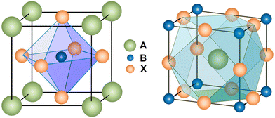 | ||
| Fig. 1 Crystal structure of the perovskite. Reproduced with permission.31 Copyright 2014, American Chemical Society. | ||
Generally, depending on the temperature, CsPbBr3 exists in three different phases including cubic α phase, tetragonal β phase, and orthogonal γ phase. At ambient temperature, CsPbBr3 perovskite resides in the stable γ phase. When the temperature increases to 88 °C, it transforms into the unstable β phase, and it will further transform into the α phase as the temperature increases above 130 °C. Once the temperature drops to room temperature, the α and β phases return to the γ phase, indicating superior stability under thermal and moisture induction.33–35
As to the photoelectric characteristics, CsPbBr3 perovskite possesses a wide bandgap of ∼2.3 eV, and can only absorb spectra with wavelengths less than ∼540 nm, which seriously restricts the improvement of the device efficiency. However, wide bandgap means a high open circuit voltage (Voc) for the corresponding device, and so far, the champion Voc of CsPbBr3 PSCs is up to 1.702 V, which is the highest among CsPbX3 PSCs.26 In addition, for CsPbBr3 single crystals, its carrier mobility is up to ∼2000 cm2 V−1 s−1, the carrier diffusion length is over 10 μm, and the carrier lifetime is approximately 2.5 μs.36,37 These superior properties facilitate charge extraction and transport. All of these parameters indicate that CsPbBr3 perovskite is an excellent light-absorbing material and has vast potential applications in the photovoltaic field.
3 Solution preparation of CsPbBr3 films
Since PbBr2 and CsBr are difficult to dissolve in one solvent at the same time, it is hard to prepare CsPbBr3 films with suitable thickness by the traditional one-step solution method. To solve the challenge of this vast solubility difference, two-step solution methods and multi-step solution methods are widely used to fabricate CsPbBr3 films. In addition, a novel one-step solution method is also proposed to obtain CsPbBr3 films with adequate thickness and purity phase.383.1 Two-step solution method
Since no solvent could be found to dissolve both CsBr and PbBr2 at the same time, Kulbak et al. utilized a two-step solution method to prepare CsPbBr3 films for the first time in 2015. As shown in Fig. 2(a), PbBr2/DMF solution was spin-coated onto the substrate, and was then dried at 75 °C for 30 minutes. Subsequently, the PbBr2-coated substrate was dipped in CsBr/methanol solution for 10 minutes and annealed at 250 °C for 10 minutes after being dried. Thus, a CsPbBr3 film with a thickness of ∼450 nm was prepared. Based on such CsPbBr3 films, the corresponding PSCs achieved a champion PCE of 5.95% using the architecture of FTO/c-TiO2/m-TiO2/CsPbBr3/PTAA/Au (Fig. 2(b)).20 However, CsPbBr3 precursor films decompose quickly when being dipped face-up in CsBr/methanol solution, thus leading to poor morphology of the CsPbBr3 films (Fig. 2(a)). In order to inhibit the decomposition, Teng et al. dipped the CsPbBr3 precursor films face-down in CsBr/methanol solution and fabricated smooth and uniform perovskite films. Based on the architecture of FTO/c-TiO2/CsPbBr3/carbon (Fig. 2(c)), the CsPbBr3 PSC achieved a PCE of 5.86%.39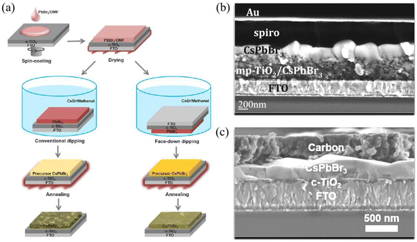 | ||
| Fig. 2 (a) Comparison between conventional dipping and surface-down dipping based on a two-step solution method. Reproduced with permission.39 Copyright 2018, American Chemical Society. Cross-sectional SEM image of photovoltaic devices based on (b) the conventional dipping method and (c) the surface-down dipping method. Reproduced with permission.20,39 Copyright 2015, American Chemical Society. | ||
Although CsPbBr3 films with suitable thickness can be fabricated by the two-step solution method, the uneven reaction between PbBr2 and CsBr results in the formation of impurity phases, such as CsPb2Br5 and Cs4PbBr6, which seriously deteriorate the performance of the photovoltaic device. Therefore, the two-step solution method needs to be improved urgently.40
3.2 Multi-step solution method
In order to reduce impurity phases and enhance the perovskite film quality, the multi-step solution method was proposed to prepare CsPbBr3 films by Duan et al.41 As shown in Fig. 3(a), after the PbBr2 layer had been deposited, CsBr/methanol solution was continuously spin-coated on the PbBr2 layer and annealed for several cycles. The reaction process is as follows| 2PbBr2 + CsBr → CsPb2Br5 (n ≤ 3) | (1) |
| CsPb2Br5 + CsBr → 2CsPbBr3 (n = 4) | (2) |
| CsPbBr3 + 3CsBr → Cs4PbBr6 (n ≥ 5) | (3) |
![[thin space (1/6-em)]](https://www.rsc.org/images/entities/char_2009.gif) :
:![[thin space (1/6-em)]](https://www.rsc.org/images/entities/char_2009.gif) 1, resulting in a pure CsPbBr3 perovskite phase; with n further increasing to above 4, an impurity phase of Cs4PbBr6 emerges due to the excess of CsBr. The CsPbBr3 films fabricated by this method appear compact and uniform, and the corresponding PSCs have achieved a champion efficiency of 9.72% based on the mesoporous structure of FTO/c-TiO2/m-TiO2/CsPbBr3/GQDs/carbon.
1, resulting in a pure CsPbBr3 perovskite phase; with n further increasing to above 4, an impurity phase of Cs4PbBr6 emerges due to the excess of CsBr. The CsPbBr3 films fabricated by this method appear compact and uniform, and the corresponding PSCs have achieved a champion efficiency of 9.72% based on the mesoporous structure of FTO/c-TiO2/m-TiO2/CsPbBr3/GQDs/carbon.
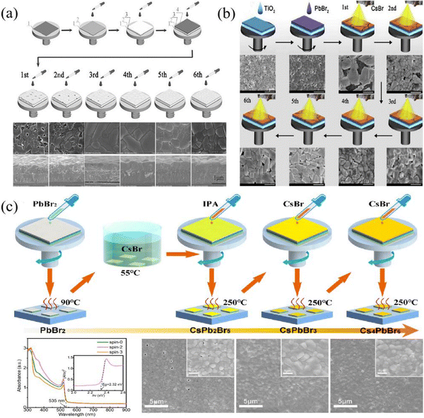 | ||
| Fig. 3 (a) Schematic illustration of the traditional multi-step solution method, reproduced with permission.41 Copyright 2018, Wiley-VCH. (b) Schematic illustration of the spray-assisted multi-step solution method. Reproduced with permission.42 Copyright 2018, Elsevier. (c) Schematic illustration of the enhanced multi-step solution method. Reproduced with permission.43 Copyright 2019, Elsevier. | ||
Considering the complicated process of the multi-step solution method, which is not conducive to commercial application, Duan et al. further improved this method; that is, a spray-assisted multi-step solution method was proposed.42 Here, PbBr2/DMF solution was first spin-coated on an m-TiO2 layer and then dried at 80 °C. Shortly after, CsBr/methanol solution was sprayed on the PbBr2 layer, followed by annealing at 250 °C, and this process was repeated several times until a high-quality CsPbBr3 film was prepared, as shown in Fig. 3(b).
Although the spray-assisted method facilitates the fabrication of large-scale photovoltaic devices and simplifies the fabrication process, it is still difficult to avoid the emergence of impurity phases. In particular, the corresponding PSCs have only obtained a PCE of 6.8%, which means that the film quality needs to be further enhanced. After that, based on the respective merits of the two-step solution method and multi-step solution method, Liu et al. fabricated high-quality CsPbBr3 films, and the process illustration is given in Fig. 3(c).43 Firstly, CsPbBr3 film with appropriate thickness was prepared by a two-step solution method, then treated with IPA solvent and annealed at 250 °C. Thereafter, the 0.07 M CsBr solution was spin-coated on the CsPbBr3 film and annealed at 250 °C; this process was repeated until a pure CsPbBr3 phase is prepared. Using this method, the fabricated CsPbBr3 film appears compact and uniform, and the grain size is close to 1 μm.
So far, highly efficient CsPbBr3 PSCs are commonly prepared by the muti-step solution method44–46 and the reported champion PCE is up to 11.08%. However, a high temperature treatment over 250 °C is necessary for CsPbBr3 films, which results in a rapid crystallization rate, leading to poor crystallinity with a non-uniform interface and high defect density in the films. In addition, the process of the muti-step solution method is too complicated, thus increasing the fabrication cost. All of these issues seriously restrict the development of CsPbBr3 PSCs, which are in urgent need of improvement.
3.3 Novel one-step solution method
Although the preparation methods of CsPbBr3 films are constantly improving, the challenge of uneven reaction between PbBr2 and CsBr remains unsolved, which leads to the generation of an impurity phase. Considering the fact that purity-phase perovskite films can be prepared by a one-step solution method, researchers have tried to use a novel one-step solution method to prepare high-quality CsPbBr3 films. Jiang et al. adopted CsAc and HPbBr3 as precursor pairs, and overcame the limitation of low solubility of CsBr, preparing compact and uniform CsPbBr3 films by a one-step solution method. The PSCs based on the above CsPbBr3 films achieved a PCE of 5.96%, which was the highest value of the same type of cells at that time.38 In 2019, Huang et al. adopted a similar one-step solution method to prepare a CsPbBr3 perovskite film, that is, CsAc and MAAc were introduced into the perovskite precursor to increase the solubility of the CsPbBr3 precursor, and a CsPbBr3 film with sufficient thickness was prepared.474 CsPbBr3 PSCs
4.1 Device structure
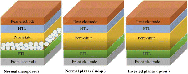
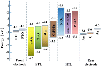
The architectures of CsPbBr3 PSCs are briefly divided into two categories: a mesoporous structure and planar structure; among them, the planar structure can be subdivided into a formal planar structure (n–i–p) and inverted planar structure (p–i–n). No matter what kind of structure, the CsPbBr3 PSCs are mainly composed of several parts, including the front electrode, electron transfer layer (ETL), perovskite layer, hole transfer layer (HTL), and rear electrode, as shown in Fig. 4. So far, the most efficient CsPbBr3 PSCs have adopted a mesoporous structure and formal planar structure.The rear electrode is usually made of metal materials (such as Au, Ag, Cu, etc.), non-metal materials (carbon electrode), and novel materials (such as Ag nanowires (NWs), Ag/Al alloys, carbon nanotubes, etc.). A superior rear electrode can facilitate carrier collection and enhance device stability and efficiency. For CsPbBr3 PSCs, because most of them adopt a mesoporous structure or formal planar structure, a carbon electrode (WF ∼5.0 eV) or Au electrode (WF ∼5.1 eV) is the most suitable, as shown in Fig. 5. In practical applications, a carbon electrode is also widely used as the back electrode, because of its low cost and high stability.
In the CsPbBr3 PSCs, TiO2 is the most commonly used ETL material; its electron mobility ranges from 0.1 to 10 cm2 V−1 s−1,53 which is not well matched with that of the CsPbBr3 layer. Therefore, some N-type metal oxide semiconductors (MOS) with good photoelectric properties (especially high carrier mobility and suitable energy level alignment), such as SnO2 (conduction-band minimum of ∼−4.3 eV, bulk electron mobility of 250 cm2 V−1 s−1),37,54,55 ZnO (conduction-band minimum of ∼−4.1 eV, bulk electron mobility of 205–300 cm2 V−1 s−1),56etc., are considered to be excellent alternatives to TiO2. For instance, the CsPbBr3 PSCs with a champion efficiency of 11.08% are fabricated with SnO2 as the ETL.26
4.2 Efficiency of CsPbBr3 PSCs
When the all-inorganic CsPbBr3 PSCs first appeared in 2015, they were prepared by a two-step solution method and achieved a PCE of 5.95% with the mesoporous structure of FTO/c-TiO2/m-TiO2/CsPbBr3/PTAA/Au.20 Subsequently, based on the same two-step solution method, Liang et al. fabricated HTL-free CsPbBr3 PSCs with the structure of FTO/c-TiO2/m-TiO2/CsPbBr3/carbon, and obtained a PCE of 6.7% as well as little hysteresis and high stability, as shown in Fig. 6(a)–(c).61 Significantly, this simplified structure eliminates the expensive organic component and noble metal electrode, and has become the classic structure of CsPbBr3 PSCs. However, the CsPbBr3 films fabricated by the two-step solution method face the challenge of impurity phases and poor crystallinity, making it difficult to prepare highly efficient devices. To obtain high-quality CsPbBr3 films, a multi-step solution method was proposed by Tang's team and a compact and uniform perovskite layer was obtained when the deposit cycle (n) equals 4. Based on the structure of FTO/c-TiO2/m-TiO2/CsPbBr3/carbon, a high PCE of 9.72% was achieved at that time, as shown in Fig. 6(d)–(f).41 At present, the highly-efficient CsPbBr3 PSCs are generally fabricated by a multi-step solution method.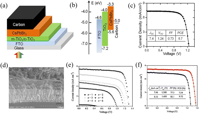 | ||
| Fig. 6 (a) The structure, (b) energy level alignment and (c) efficiency of the classic CsPbBr3 PSCs based on the two-step solution method. Reproduced with permission.61 Copyright 2016, American Chemical Society. (d) The cross-sectional SEM image, (e) J–V curves for different cycles (n) and (f) champion efficiency of the CsPbBr3 PSCs based on the multi-step solution method. Reproduced with permission.41 Copyright 2018, Wiley-VCH. | ||
Based on the above study, in order to further improve the performance of CsPbBr3 PSCs, various optimization strategies have been reported, such as additive engineering,28,62 interface engineering,63–65 carrier transfer layer optimization,45,66 electrode optimization,29,67 and so on. Table 1 demonstrates the performance parameters of typical CsPbBr3 PSCs fabricated by the multi-step solution method reported in the last 5 years.
| Device structure | Optimization strategy | PCE (%) | V oc (V) | J sc (mA cm−2) | FF (%) | Publication time | Ref. |
|---|---|---|---|---|---|---|---|
| FTO/c-TiO2/m-TiO2/CQDs/CsPbBr3/carbon (PtNi NWs) | Interface engineering | 7.86 | 1.432 | 6.78 | 81 | 2018.5 | 68 |
| Electrode optimization | |||||||
| FTO/c-TiO2/m-TiO2/CQDs/CsPbBr3/PQDs/carbon | Interface engineering | 7.93 | 1.45 | 7.24 | 75.6 | 2018.7 | 69 |
| FTO/c-TiO2/m-TiO2/CsPbBr3/CsSnBr2I QDs/carbon | Interface engineering | 9.13 | 1.39 | 8.7 | 75.5 | 2018.9 | 70 |
| FTO/c-TiO2/m-TiO2/CsPb0.97Sm0.03Br3/carbon | Additive engineering | 10.14 | 1.594 | 7.48 | 85.1 | 2018.11 | 71 |
| FTO/c-TiO2/m-TiO2/CsPbBr3/carbon | Electrode optimization | 7.62 | 1.431 | 6.84 | 78 | 2018.11 | 72 |
| FTO/c-TiO2/m-TiO2/CsPbBr3/BT-BTH/carbon | Novel HTL | 9.32 | 1.5 | 7.56 | 81.9 | 2018.12 | 73 |
| FTO/SnO2 QDs/CsPbBr3/CsSnBr3 QDs/carbon | ETL optimization | 10.6 | 1.61 | 7.8 | 84.4 | 2019.3 | 74 |
| Interface engineering | |||||||
| FTO/c-TiO2/m-TiO2/CsPb0.97Sr0.03Br3/carbon | Additive engineering | 9.63 | 1.54 | 7.71 | 81.1 | 2019.3 | 75 |
| FTO/c-TiO2/m-TiO2/CsPbBr3/P1Z1/carbon | HTL optimization | 10.03 | 1.578 | 7.652 | 83.1 | 2019.5 | 76 |
| FTO/c-TiO2/m-TiO2/CsPb0.995Zn0.005Br3/carbon | Additive engineering | 9.18 | 1.56 | 7.3 | 80.6 | 2019.11 | 77 |
| FTO/c-TiO2/m-TiO2/CsPb0.97Sm0.03Br3/Cu(Cr,Ba)O2/carbon | Additive engineering | 10.79 | 1.615 | 7.81 | 85.5 | 2019.11 | 28 |
| Novel HTL | |||||||
| FTO/c-TiO2/m-TiO2/Cs0.91Rb0.09PbBr3/J61-ITIC/carbon | Additive engineering | 10.34 | 1.58 | 8.18 | 80 | 2019.11 | 78 |
| Novel HTL | |||||||
| FTO/c-TiO2/m-TiO2/CsPbBr3/PVAc/GO/carbon | Interface engineering | 9.53 | 1.553 | 7.41 | 82.8 | 2019.12 | 79 |
| FTO/c-TiO2/m-TiO2/CsPbBr3/CsPbI3 NC/carbon | Interface engineering | 9.45 | 1.49 | 8.66 | 73.2 | 2019.12 | 80 |
| FTO/c-TiO2/m-TiO2/CsPbBr3/C12-QDs/LPP-carbon | Novel HTL | 10.85 | 1.626 | 7.73 | 86.3 | 2020.1 | 29 |
| Electrode optimization | |||||||
| FTO/c-TiO2/m-TiO2/CsPbBr3/[BMMIm]Cl/carbon | Interface engineering | 9.92 | 1.61 | 7.45 | 83 | 2020.1 | 81 |
| FTO/c-TiO2/m-TiO2/CsPbBr3/carbon-PANi/G | Electrode optimization | 8.87 | 1.59 | 6.87 | 81.2 | 2020.2 | 82 |
| FTO/c-TiO2/m-TiO2/CsPbBr3/carbon | Additive engineering | 9.65 | 1.584 | 7.42 | 82.1 | 2020.4 | 83 |
| FTO/c-TiO2/m-TiO2/CsPbBr3/MoO2/NC/carbon | Interface engineering | 9.4 | 1.532 | 7.2 | 85.2 | 2020.6 | 84 |
| FTO/c-TiO2/m-TiO2/CsPbBr3/carbon | Additive engineering | 9.68 | 1.565 | 7.64 | 81 | 2020.8 | 85 |
| FTO/c-TiO2/m-TiO2/AC/CsPbBr3/ZnPc/carbon | Interface engineering | 10.12 | 1.606 | 7.64 | 82.5 | 2020.1 | 86 |
| FTO/c-TiO2/m-TiO2/UV-360/CsPbBr3/carbon | Interface engineering | 9.61 | 1.568 | 7.69 | 79.7 | 2021.1 | 87 |
| FTO/c-TiO2/m-TiO2/CsPbBr3 + Br-GO/Br-GO/carbon | Additive engineering | 10.1 | 1.602 | 7.88 | 80.0 | 2021.5 | 88 |
| HTL optimization | |||||||
| FTO/2D SnO2/GQDs/CsPbBr3/carbon | Interface engineering | 10.34 | 1.585 | 7.94 | 82.2 | 2021.3 | 89 |
| FTO/L-TiO2/CsPbBr3/carbon | Interface engineering | 10.75 | 1.675 | 7.58 | 84.6 | 2021.6 | 64 |
| FTO/SnO2–RbCl/CsPbBr3/carbon | ETL optimization | 10.04 | 1.601 | 7.69 | 81.6 | 2021.7 | 66 |
| FTO/TiO2/CsPbBr3/Pt3Co–carbon | Electrode optimization | 9.08 | 1.574 | 7.24 | 79.7 | 2021.8 | 67 |
| FTO/c-TiO2/m-TiO2/CsPbBr3/HMTA/carbon | Interface engineering | 10.08 | 1.605 | 7.51 | 83.6 | 2021.6 | 90 |
| FTO/SnO2/CsPbBr3-Ti3C2Clx/Ti3C2Clx/carbon | Interface engineering | 11.08 | 1.702 | 7.87 | 82.7 | 2021.1 | 26 |
| Additive engineering | |||||||
| FTO/c-TiO2/m-TiO2/CsPbBr3/DCC/carbon | Interface engineering | 10.16 | 1.611 | 7.79 | 80.9 | 2022.1 | 91 |
| FTO/c-TiO2/m-TiO2/CsPbBr3/ReSe2/carbon | Interface engineering | 10.67 | 1.622 | 7.92 | 83.1 | 2022.2 | 92 |
| FTO/c-TiO2/m-TiO2/ASF/CsPbBr3/carbon | Interface engineering | 10.08 | 1.615 | 7.47 | 83.6 | 2022.3 | 93 |
| FTO/SnO2–SnS2/CsPbBr3/carbon | ETL optimization | 10.72 | 1.635 | 7.8 | 84.0 | 2022.6 | 45 |
| FTO/c-TiO2/m-TiO2/CsPbBr3/carbon | Interface engineering | 10.71 | 1.65 | 7.83 | 82.9 | 2022.9 | 94 |
| FTO/c-TiO2/m-TiO2/CsPbBr3-HAM/carbon | Additive engineering | 9.05 | 1.468 | 7.54 | 81.7 | 2023.2 | 95 |
| FTO/TiO2/CsPbBr3/PEO/carbon | Interface engineering | 8.84 | 1.495 | 7.8 | 75.8 | 2023.3 | 96 |
| FTO/c-TiO2/m-TiO2/CsPbBr3/PAMPS/NQDs/carbon | Interface engineering | 10.21 | 1.632 | 7.59 | 82.4 | 2023.4 | 97 |
Using the same strategy, Zhao et al. introduced alkaline earth metal cations (Mg2+, Ca2+, Sr2+, Ba2+) into CsPbBr3 perovskite, partially replacing Pb2+. After additive passivation (especially Sr2+), high-quality CsPbBr3 films with a smooth surface and big grain size are obtained, as shown in Fig. 7(a) and (b). In addition, based on the structure of FTO/c-TiO2/m-TiO2/CsPb0.97Sr0.03Br3/carbon, a PCE of 9.63% was obtained (Fig. 7(c) and (d)), and the device stability was also significantly enhanced. Under the condition of 80% relative humidity, the efficiency of the unencapsulated PSCs remained above 80% of the initial value when the light illumination lasted for 800 hours.75 In particular, Tang's team incorporated Ti3C2Clx MXene into CsPbBr3 film to realize strain release and defect passivation in the bulk and surface, and finally obtained high-performance CsPbBr3 PSCs with a PCE of 11.08% and a Voc of 1.702 V, which were the highest values thus far. The device structure is FTO/SnO2/CsPbBr3–Ti3C2Clx/Ti3C2Clx/carbon, as shown in Fig. 7(e) and (f).26 Similar additive engineering has also been performed for Lanthanide metal cations, Zn2+, Rb+, and so on.71,77,78
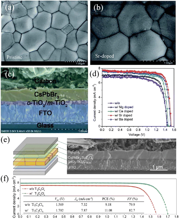 | ||
| Fig. 7 Top-view SEM images of (a) pristine and (b) Sr-doped CsPbBr3 films fabricated by the multi-step solution method, (c) cross-sectional SEM image of the CsPbBr3 PSC based on the structure of FTO/c-TiO2/m-TiO2/CsPb0.97Sr0.03Br3/carbon, and (d) J–V curves of CsPbBr3 PSCs doped with different alkaline earth metals. Reproduced with permission.75 Copyright 2018, Royal Society of Chemistry. (e) Structure and (f) J–V curves of CsPbBr3 PSCs passivated by Ti3C2Clx. Reproduced with permission.26 Copyright 2021, Wiley-VCH. | ||
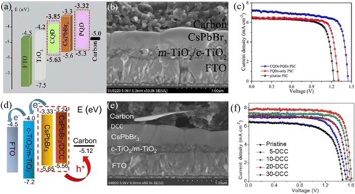 | ||
| Fig. 8 (a) The energy level alignment, (b) cross-sectional SEM image and (c) efficiency of CQD/PQD-modified CsPbBr3 PSCs. Reproduced with permission.69 Copyright 2018, Elsevier. (d) The energy level alignment, (e) cross-sectional SEM image and (f) efficiency of DCC-modified CsPbBr3 PSCs. Reproduced with permission.91 Copyright 2021, Copyright 2018, Elsevier. | ||
![[thin space (1/6-em)]](https://www.rsc.org/images/entities/char_2009.gif) :
:![[thin space (1/6-em)]](https://www.rsc.org/images/entities/char_2009.gif) ZnPc = 1
ZnPc = 1![[thin space (1/6-em)]](https://www.rsc.org/images/entities/char_2009.gif) :
:![[thin space (1/6-em)]](https://www.rsc.org/images/entities/char_2009.gif) 1 (P1Z1), a champion PCE as high as 10.3% was achieved based on the structure of FTO/c-TiO2/m-TiO2/CsPbBr3/P1Z1/carbon.76 Also based on ETL optimization, Zhao et al. utilized optimized SnO2 QDs as the ETL, and the efficiency of the device with the architecture of FTO/SnO2 QDs/CsPbBr3/carbon reached 9.15%. When further introducing a CsSnBr3 QD layer as a bridge energy level to reduce the interface energy barrier, the device based on the FTO/SnO2 QDs/CsPbBr3/CsSnBr3 QDs/carbon structure achieved a high PCE of 10.6% with a Voc of 1.610 V.74
1 (P1Z1), a champion PCE as high as 10.3% was achieved based on the structure of FTO/c-TiO2/m-TiO2/CsPbBr3/P1Z1/carbon.76 Also based on ETL optimization, Zhao et al. utilized optimized SnO2 QDs as the ETL, and the efficiency of the device with the architecture of FTO/SnO2 QDs/CsPbBr3/carbon reached 9.15%. When further introducing a CsSnBr3 QD layer as a bridge energy level to reduce the interface energy barrier, the device based on the FTO/SnO2 QDs/CsPbBr3/CsSnBr3 QDs/carbon structure achieved a high PCE of 10.6% with a Voc of 1.610 V.74
4.3 Stability of CsPbBr3 PSCs
Device stability is one of the important indicators for the commercialization of perovskite PSCs. Although the organic–inorganic hybrid PSCs have achieved high efficiency, the device instability hinders their further development.101–104 In contrast, CsPbBr3 perovskite is the most stable CsPbIxBr3−x perovskite so far, possessing robust stability under the induction of heat, humidity and light. Coupled with the high stability of the functional layer and electrode materials, CsPbBr3 PSCs generally reveal superb long-term stability.105,106 Kulbak et al. initially utilized inorganic cation Cs+ instead of organic cation MA+ to fabricate all-inorganic CsPbBr3 PSCs, and direct comparisons in terms of photovoltaic performance and stability were performed between CsPbBr3 PSCs and MAPbBr3 PSCs. Further studies demonstrated that both types of device achieved similar photovoltaic performance, while CsPbBr3 PSCs revealed much better thermal stability compared with MAPbBr3 PSCs. All the performance parameters of CsPbBr3 PSCs including Voc, Jsc, FF and PCE showed no remarkable decay under continuous light illumination for 14 days.21 This result also confirms that the substitution of volatile organic cations with inorganic cations is an effective means to improve device stability.Subsequently, Liang et al. fabricated all-inorganic PSCs without any volatile materials or expensive electrode. Based on the classical HTL-free structure of FTO/c-TiO2/m-TiO2/CsPbBr3/carbon, the fabricated CsPbBr3 PSCs yielded a PCE of 6.7% and demonstrated superb stability under the induction of high temperature (100 °C) and high humidity (90–95%RH), as depicted in Fig. 9(a)–(c).61
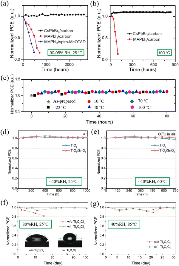 | ||
| Fig. 9 Normalized PCEs of CsPbBr3-based and MAPbI3-based PSCs as a function of storage time without encapsulation (a) in humid air (90–95% RH, 25 °C) and (b) at high temperature (100 °C). (c) Normalized PCEs of CsPbBr3-based PSCs as a function of storage time during temperature cycling (between −22 °C and 100 °C) in a high-humidity ambient environment. Reproduced with permission.61 Copyright 2016, American Chemical Society. Normalized PCEs of the TiO2-based and TiO2/SnO2-based PSCs when stored in ambient air with a relative humidity of ∼40% at (d) room temperature (25 °C) for over 1000 h and (e) 60 °C for 720 h, respectively. Reproduced with permission.43 Copyright 2019, Elsevier. Normalized PCEs of the encapsulation-free devices with and without Ti3C2Clx in air under (f) 25 °C, 80%RH and (g) 85 °C, 40% RH conditions. Reproduced with permission.26 Copyright 2021, Wiley-VCH. | ||
In 2019, based on the structure of FTO/c-TiO2/SnO2/CsPbBr3/CuPc/carbon, Liu et al. fabricated bilayered ETL CsPbBr3 PSCs with all-inorganic functional layers and obtained a PCE of 8.79%.43 The device stability was extremely excellent, as shown in Fig. 7(b). When stored under ambient conditions (∼40%RH, 25 °C) for over 1000 hours, both devices (including TiO2-based and TiO2/SnO2-based devices) exhibited superior stability with no efficiency decay. If the temperature increased to 60 °C for 720 hours, the efficiency of the TiO2/SnO2-based device remains almost unchanged, while only 97.4% efficiency remained for TiO2-based devices (Fig. 9(d) and (e)). The results means that the introduction of a bilayer ETL facilitates the enhancement of the device efficiency and stability.
After that, based on the structure of FTO/SnO2/CsPbBr3–Ti3C2Clx/Ti3C2Clx/carbon, Zhou et al. prepared a CsPbBr3 PSC with an efficiency of 11.08%, adopting the hydrophobic material Ti3C2Clx as a passivator and intermediate energy-level layer. The results of stability measurement are shown in Fig. 9(f) and (g). Under high humidity conditions (80%RH), an unencapsulated PSC with Ti3C2Clx showed little degradation after 100 days of storage, which is much superior to CsPbBr3 PSCs without Ti3C2Clx. Under high temperature conditions (85 °C), with or without Ti3C2Clx, the efficiency of the unencapsulated PSCs remained unchanged after 30 days of storage, indicating that the hydrophobic material as a functional layer can effectively improve the device humidity stability.
5 Conclusion and prospects
In this review, the material properties, film preparation, device structure and performance of CsPbBr3 PSCs are systematically introduced. Attributed to its high stability and wide bandgap, CsPbBr3 perovskite exhibits huge potential applications in semitransparent and tandem solar cells.107–109 However, the low efficiency of CsPbBr3 PSCs hinders its commercialization progress due to the poor crystallinity of the absorber layer. At present, great efforts are focused on the optimization strategies of CsPbBr3 PSCs, including additive engineering, interface engineering, optimization of the HTL and ETL, optimization of electrode, and so on. Based on the aforementioned strategies, the PCE of the CsPbBr3 PSCs quickly increased from the initial 5.95% to the current 11.08%, and demonstrated further upward momentum. In addition, the device stability can also be strengthened by the introduction and optimization of a high stability functional layer material.Unfortunately, although the current efficiency of CsPbBr3 PSCs has reached 11.08%, it is still far behind the S–Q limit value of 16.37%, and thus there is large room for improvement. To further enhance the performance of CsPbBr3 PSCs, the next efforts should focus on the following aspects: (1) simplifying the preparation process of CsPbBr3 films, transferring from a multi-step solution method to a novel one-step solution method, and avoiding the appearance of an impurity phase; (2) developing novel function layer materials with more suitable bandgaps, or regulating the bandgap of existing materials, so as to achieve energy level matching between the CsPbBr3 layer and carrier transfer layer, and reduce the energy loss caused by the excessive energy level difference; (3) adding a modification layer at the interfaces of perovskite/HTL or perovskite/ETL to smooth the bandgap, and reduce the non-radiative recombination of carriers, thus improving the efficiency of CsPbBr3 PSCs.
Author contributions
All authors contributed to the writing of the manuscript.Conflicts of interest
There are no conflicts to declare.Acknowledgements
The authors acknowledge the financial support from the Scientific Research Programs of Educational Department of Hebei Province of China (B2021213), and the National Natural Science Foundation of China (12134010, 12174290).References
- H. J. Snaith, J. Phys. Chem. Lett., 2013, 4, 3623–3630 CrossRef CAS.
- G. E. Eperon, S. D. Stranks, C. Menelaou, M. B. Johnston, L. M. Herz and H. J. Snaith, Energy Environ. Sci., 2014, 7, 982 RSC.
- C. Wehrenfennig, G. E. Eperon, M. B. Johnston, H. J. Snaith and L. M. Herz, Adv. Mater., 2013, 26, 1584–1589 CrossRef PubMed.
- S. D. Stranks, G. E. Eperon, G. Grancini, C. Menelaou, M. J. P. Alcocer, T. Leijtens, L. M. Herz, A. Petrozza and H. J. Snaith, Science, 2013, 342, 341–344 CrossRef CAS PubMed.
- J. H. Noh, S. H. Im, J. H. Heo, T. N. Mandal and S. I. Seok, Nano Lett., 2013, 13, 1764–1769 CrossRef CAS PubMed.
- Y. Liu, M. Bag, L. A. Renna, Z. A. Page, P. Kim, T. Emrick, D. Venkataraman and T. P. Russell, Adv. Energy Mater., 2016, 6, 1501606 CrossRef.
- J.-Y. Jeng, Y.-F. Chiang, M.-H. Lee, S.-R. Peng, T.-F. Guo, P. Chen and T.-C. Wen, Adv. Mater., 2013, 25, 3727–3732 CrossRef CAS.
- X. Luo, X. Lin, F. Gao, Y. Zhao, X. Li, L. Zhan, Z. Qiu, J. Wang, C. Chen, L. Meng, X. Gao, Y. Zhang, Z. Huang, R. Fan, H. Liu, Y. Chen, X. Ren, J. Tang, C.-H. Chen, D. Yang, Y. Tu, X. Liu, D. Liu, Q. Zhao, J. You, J. Fang, Y. Wu, H. Han, X. Zhang, D. Zhao, F. Huang, H. Zhou, Y. Yuan, Q. Chen, Z. Wang, S. F. Liu, R. Zhu, J. Nakazaki, Y. Li and L. Han, Sci. China: Chem., 2022, 65, 2369–2416 CrossRef CAS.
- J. P. Correa-Baena, M. Saliba, T. Buonassisi, M. Gratzel, A. Abate, W. Tress and A. Hagfeldt, Science, 2017, 358, 739–744 CrossRef CAS PubMed.
- C. Wehrenfennig, G. E. Eperon, M. B. Johnston, H. J. Snaith and L. M. Herz, Adv. Mater., 2014, 26, 1584–1589 CrossRef CAS.
- G. Xing, N. Mathews, S. Sun, S. S. Lim, Y. M. Lam, M. Grätzel, S. Mhaisalkar and T. C. Sum, Science, 2013, 342, 344–347 CrossRef CAS PubMed.
- https://www.nrel.gov/pv/cell-efficiency.html .
- B. w Park and S. I. Seok, Adv. Mater., 2019, 31, 1805337 CrossRef.
- H. Cho, Y.-H. Kim, C. Wolf, H.-D. Lee and T.-W. Lee, Adv. Mater., 2018, 30, 1704587 CrossRef PubMed.
- L. Zuo, Z. Li and H. Chen, Chin. J. Chem., 2023, 41, 861–876 CrossRef CAS.
- J.-W. Lee, D.-H. Kim, H.-S. Kim, S.-W. Seo, S. M. Cho and N.-G. Park, Adv. Energy Mater., 2015, 5, 1501310 CrossRef.
- C. Li, A. Wang, L. Xie, X. Deng, K. Liao, J.-A. Yang, T. Li and F. Hao, J. Mater. Chem. A, 2019, 7, 24150–24163 RSC.
- G. E. Eperon, G. M. Paternò, R. J. Sutton, A. Zampetti, A. A. Haghighirad, F. Cacialli and H. J. Snaith, J. Mater. Chem. A, 2015, 3, 19688–19695 RSC.
- S. Tan, C. Tan, Y. Cui, B. Yu, Y. Li, H. Wu, J. Shi, Y. Luo, D. Li and Q. Meng, Adv. Mater., 2023, 35, 2301879 CrossRef CAS.
- M. Kulbak, D. Cahen and G. Hodes, J. Phys. Chem. Lett., 2015, 6, 2452–2456 CrossRef CAS PubMed.
- M. Kulbak, S. Gupta, N. Kedem, I. Levine, T. Bendikov, G. Hodes and D. Cahen, J. Phys. Chem. Lett., 2016, 7, 167–172 CrossRef CAS PubMed.
- R. J. Sutton, G. E. Eperon, L. Miranda, E. S. Parrott, B. A. Kamino, J. B. Patel, M. T. Hörantner, M. B. Johnston, A. A. Haghighirad, D. T. Moore and H. J. Snaith, Adv. Energy Mater., 2016, 6, 1502458 CrossRef.
- J. Ma, M. Qin, Y. Li, X. Wu, Z. Qin, Y. Wu, G. Fang and X. Lu, Matter, 2021, 4, 313–327 CrossRef CAS.
- N. Kumar, J. Rani and R. Kurchania, Sol. Energy, 2021, 221, 197–205 CrossRef CAS.
- M. B. Faheem, B. Khan, C. Feng, M. U. Farooq, F. Raziq, Y. Xiao and Y. Li, ACS Energy Lett., 2019, 5, 290–320 CrossRef.
- Q. Zhou, J. Duan, J. Du, Q. Guo, Q. Zhang, X. Yang, Y. Duan and Q. Tang, Adv. Sci., 2021, 8, 2101418 CrossRef CAS.
- S. Rühle, Sol. Energy, 2016, 130, 139–147 CrossRef.
- J. Duan, Y. Zhao, Y. Wang, X. Yang and Q. Tang, Angew. Chem., Int. Ed., 2019, 58, 16147–16151 CrossRef CAS PubMed.
- J. Duan, Y. Wang, X. Yang and Q. Tang, Angew. Chem., Int. Ed., 2020, 59, 4391–4395 CrossRef CAS.
- G. Tong, T. Chen, H. Li, L. Qiu, Z. Liu, Y. Dang, W. Song, L. K. Ono, Y. Jiang and Y. Qi, Nano Energy, 2019, 65, 104015 CrossRef CAS.
- H.-S. Kim, S. H. Im and N.-G. Park, J. Phys. Chem. C, 2014, 118, 5615–5625 CrossRef CAS.
- A. Swarnkar, W. J. Mir and A. Nag, ACS Energy Lett., 2018, 3, 286–289 CrossRef CAS.
- C. C. Stoumpos, C. D. Malliakas, J. A. Peters, Z. Liu, M. Sebastian, J. Im, T. C. Chasapis, A. C. Wibowo, D. Y. Chung, A. J. Freeman, B. W. Wessels and M. G. Kanatzidis, Cryst. Growth Des., 2013, 13, 2722–2727 CrossRef CAS.
- J. Cheng, Z. Fan and J. Dong, Nanomaterials, 2023, 13, 991 CrossRef CAS PubMed.
- J. Deng, J. Li, Z. Yang and M. Wang, J. Mater. Chem. C, 2019, 7, 12415–12440 RSC.
- J. Song, Q. Cui, J. Li, J. Xu, Y. Wang, L. Xu, J. Xue, Y. Dong, T. Tian, H. Sun and H. Zeng, Adv. Opt. Mater., 2017, 5, 1700157 CrossRef.
- P. Tiwana, P. Docampo, M. B. Johnston, H. J. Snaith and L. M. Herz, ACS Nano, 2011, 5, 5158–5166 CrossRef CAS.
- Y. Jiang, J. Yuan, Y. Ni, J. Yang, Y. Wang, T. Jiu, M. Yuan and J. Chen, Joule, 2018, 2, 1356–1368 CrossRef.
- P. Teng, X. Han, J. Li, Y. Xu, L. Kang, Y. Wang, Y. Yang and T. Yu, ACS Appl. Mater. Interfaces, 2018, 10, 9541–9546 CrossRef CAS PubMed.
- J. Feng, X. Han, H. Huang, Q. Meng, Z. Zhu, T. Yu, Z. Li and Z. Zou, Sci. Bull., 2020, 65, 726–737 CrossRef CAS.
- J. Duan, Y. Zhao, B. He and Q. Tang, Angew. Chem., Int. Ed., 2018, 57, 3787–3791 CrossRef CAS PubMed.
- J. Duan, D. Dou, Y. Zhao, Y. Wang, X. Yang, H. Yuan, B. He and Q. Tang, Mater. Today Energy, 2018, 10, 146–152 CrossRef.
- X. Liu, X. Tan, Z. Liu, H. Ye, B. Sun, T. Shi, Z. Tang and G. Liao, Nano Energy, 2019, 56, 184–195 CrossRef CAS.
- B. Gao and J. Meng, Sol. Energy, 2020, 211, 1223–1229 CrossRef CAS.
- X. Yao, B. He, J. Zhu, J. Ti, L. Cui, R. Tui, M. Wei, H. Chen, J. Duan, Y. Duan and Q. Tang, Nano Energy, 2022, 96, 107138 CrossRef CAS.
- S. Wang, F. Cao, W. Sun, C. Wang, Z. Yan, N. Wang, Z. Lan and J. Wu, Mater. Today Phys., 2022, 22, 100614 CrossRef CAS.
- D. Huang, P. Xie, Z. Pan, H. Rao and X. Zhong, J. Mater. Chem. A, 2019, 7, 22420–22428 RSC.
- N. Singh, A. Mohapatra, C.-W. Chu and Y.-T. Tao, Org. Electron., 2021, 98, 106297 CrossRef CAS.
- J. Dou, J. Tan, B. He, J. Duan and Q. Tang, Dalton Trans., 2023, 52, 6146–6151 RSC.
- B. Roose, K. C. Gödel, S. Pathak, A. Sadhanala, J. P. C. Baena, B. D. Wilts, H. J. Snaith, U. Wiesner, M. Grätzel, U. Steiner and A. Abate, Adv. Energy Mater., 2016, 6, 1501868 CrossRef.
- M. M. Tavakoli, P. Yadav, R. Tavakoli and J. Kong, Adv. Energy Mater., 2018, 8, 1800794 CrossRef.
- Y. Xu, J. Duan, X. Yang, J. Du, Y. Wang, Y. Duan and Q. Tang, J. Mater. Chem. A, 2020, 8, 11859–11866 RSC.
- C. S. Ponseca, Jr., T. J. Savenije, M. Abdellah, K. Zheng, A. Yartsev, T. Pascher, T. Harlang, P. Chabera, T. Pullerits, A. Stepanov, J. P. Wolf and V. Sundstrom, J. Am. Chem. Soc., 2014, 136, 5189–5192 CrossRef PubMed.
- H.-S. Rao, B.-X. Chen, W.-G. Li, Y.-F. Xu, H.-Y. Chen, D.-B. Kuang and C.-Y. Su, Adv. Funct. Mater., 2015, 25, 7200–7207 CrossRef CAS.
- Q. Jiang, X. Zhang and J. You, Small, 2018, 14(31), 1801154 CrossRef.
- Q. Zhang, C. S. Dandeneau, X. Zhou and G. Cao, Adv. Mater., 2009, 21, 4087–4108 CrossRef CAS.
- H. S. Kim, C. R. Lee, J. H. Im, K. B. Lee, T. Moehl, A. Marchioro, S. J. Moon, R. Humphry-Baker, J. H. Yum, J. E. Moser, M. Grätzel and N. G. Park, Sci. Rep., 2012, 2, 591 CrossRef.
- N. J. Jeon, J. H. Noh, Y. C. Kim, W. S. Yang, S. Ryu and S. I. Seok, Nat. Mater., 2014, 13, 897–903 CrossRef CAS.
- E. H. Jung, N. J. Jeon, E. Y. Park, C. S. Moon, T. J. Shin, T.-Y. Yang, J. H. Noh and J. Seo, Nature, 2019, 567, 511–515 CrossRef CAS.
- Z. Y. Liu, B. Sun, X. Y. Liu, J. H. Han, H. B. Ye, T. L. Shi, Z. R. Tang and G. L. Liao, Nano-Micro Lett., 2018, 10, 1–13 CrossRef.
- J. Liang, C. X. Wang, Y. R. Wang, Z. R. Xu, Z. P. Lu, Y. Ma, H. F. Zhu, Y. Hu, C. C. Xiao, X. Yi, G. Y. Zhu, H. L. Lv, L. B. Ma, T. Chen, Z. X. Tie, Z. Jin and J. Liu, J. Am. Chem. Soc., 2016, 138, 15829–15832 CrossRef CAS.
- F. Zhang and K. Zhu, Adv. Energy Mater., 2020, 10, 1902579 CrossRef CAS.
- G. Liao, J. Duan, Y. Zhao and Q. Tang, Sol. Energy, 2018, 171, 279–285 CrossRef CAS.
- J. Duan, M. Wang, Y. Wang, J. Zhang, Q. Guo, Q. Zhang, Y. Duan and Q. Tang, ACS Energy Lett., 2021, 6, 2336–2342 CrossRef CAS.
- H. Li, G. Tong, T. Chen, H. Zhu, G. Li, Y. Chang, L. Wang and Y. Jiang, J. Mater. Chem. A, 2018, 6, 14255–14261 RSC.
- G. Xie, X. Lu, J. Duan, Y. Dong, X. Jiang, F. Tu, Y. Duan and Q. Tang, J. Mater. Chem. A, 2021, 9, 15003–15011 RSC.
- Y. Zhao, J. Zhu, B. He and Q. Tang, Chem. Commun., 2021, 57, 7577–7580 RSC.
- J. Ding, Y. Zhao, J. Duan, B. He and Q. Tang, ChemSusChem, 2018, 11, 1432–1437 CrossRef CAS.
- H. W. Yuan, Y. Y. Zhao, J. L. Duan, B. L. He, Z. B. Jiao and Q. W. Tang, Electrochim. Acta, 2018, 279, 84–90 CrossRef CAS.
- H. Xu, J. Duan, Y. Zhao, Z. Jiao, B. He and Q. Tang, J. Power Sources, 2018, 399, 76–82 CrossRef CAS.
- J. Duan, Y. Zhao, X. Yang, Y. Wang, B. He and Q. Tang, Adv. Energy Mater., 2018, 8, 1802346 CrossRef.
- G. Liao, Y. Zhao, J. Duan, H. Yuan, Y. Wang, X. Yang, B. He and Q. Tang, Dalton Trans., 2018, 47, 15283–15287 RSC.
- Y. Zhao, T. Liu, F. Ren, J. Duan, Y. Wang, X. Yang, Q. Li and Q. Tang, Mater. Chem. Front., 2018, 2, 2239–2244 RSC.
- Y. Zhao, J. Duan, H. Yuan, Y. Wang, X. Yang, B. He and Q. Tang, Sol. RRL, 2019, 3, 1800284 CrossRef.
- Y. Zhao, Y. Wang, J. Duan, X. Yang and Q. Tang, J. Mater. Chem. A, 2019, 7, 6877–6882 RSC.
- Y. Liu, B. He, J. Duan, Y. Zhao, Y. Ding, M. Tang, H. Chen and Q. Tang, J. Mater. Chem. A, 2019, 7, 12635–12644 RSC.
- M. Tang, B. He, D. Dou, Y. Liu, J. Duan, Y. Zhao, H. Chen and Q. Tang, Chem. Eng. J., 2019, 375, 121930 CrossRef CAS.
- Y. Zhao, H. Xu, Y. Wang, X. Yang, J. Duan and Q. Tang, J. Power Sources, 2019, 440, 227151 CrossRef CAS.
- Y. Ding, B. He, J. Zhu, W. Zhang, G. Su, J. Duan, Y. Zhao, H. Chen and Q. Tang, ACS Sustainable Chem. Eng., 2019, 7, 19286–19294 CrossRef CAS.
- G. Su, B. He, Z. Gong, Y. Ding, J. Duan, Y. Zhao, H. Chen and Q. Tang, Electrochim. Acta, 2019, 328, 135102 CrossRef CAS.
- W. Zhang, X. Liu, B. He, Z. Gong, J. Zhu, Y. Ding, H. Chen and Q. Tang, ACS Appl. Mater. Interfaces, 2020, 12, 4540–4548 CrossRef CAS PubMed.
- F. Bu, B. He, Y. Ding, X. Li, X. Sun, J. Duan, Y. Zhao, H. Chen and Q. Tang, Sol. Energy Mater. Sol. Cells, 2020, 205, 110267 CrossRef CAS.
- J. Zhu, B. He, Z. Gong, Y. Ding, W. Zhang, X. Li, Z. Zong, H. Chen and Q. Tang, ChemSusChem, 2020, 13, 1834–1843 CrossRef CAS PubMed.
- Z. Zong, B. He, J. Zhu, Y. Ding, W. Zhang, J. Duan, Y. Zhao, H. Chen and Q. Tang, Sol. Energy Mater. Sol. Cells, 2020, 209, 110460 CrossRef CAS.
- W. Zhang, X. Liu, B. He, J. Zhu, X. Li, K. Shen, H. Chen, Y. Duan and Q. Tang, ACS Appl. Mater. Interfaces, 2020, 12, 36092–36101 CrossRef CAS PubMed.
- J. Zhu, M. Tang, B. He, W. Zhang, X. Li, Z. Gong, H. Chen, Y. Duan and Q. Tang, J. Mater. Chem. A, 2020, 8, 20987–20997 RSC.
- J. Zhu, M. Tang, B. He, K. Shen, W. Zhang, X. Sun, M. Sun, H. Chen, Y. Duan and Q. Tang, Chem. Eng. J., 2021, 404, 126548 CrossRef CAS.
- X. Sun, B. He, J. Zhu, R. Zhu, H. Chen, Y. Duan and Q. Tang, Chem. Eng. J., 2021, 412, 128727 CrossRef CAS.
- Y. Zhao, J. Zhu, B. He and Q. Tang, ACS Appl. Mater. Interfaces, 2021, 13, 11058–11066 CrossRef CAS PubMed.
- M. Sun, J. Zhu, B. He, F. Bu, J. Ti, X. Yao, H. Chen, Y. Duan and Q. Tang, Sol. RRL, 2021, 5, 2100344 CrossRef CAS.
- J. Zhu, Y. Liu, B. He, W. Zhang, L. Cui, S. Wang, H. Chen, Y. Duan and Q. Tang, Chem. Eng. J., 2022, 428, 131950 CrossRef CAS.
- J. Zhu, B. He, X. Yao, H. Chen, Y. Duan, J. Duan and Q. Tang, Small, 2022, 18, 2106323 CrossRef CAS.
- L. Cui, B. He, Y. Ding, J. Zhu, X. Yao, J. Ti, H. Chen, Y. Duan and Q. Tang, Chem. Eng. J., 2022, 431, 134193 CrossRef CAS.
- J. Zhu, B. He, W. Zhang, R. Tui, H. Chen, Y. Duan, H. Huang, J. Duan and Q. Tang, Adv. Funct. Mater., 2022, 32, 2206838 CrossRef CAS.
- Y. Jiao, X. Yao, F. Bao, J. Mao, H. Chen, Y. Duan, P. Yang, Q. Tang and B. He, Sol. RRL, 2022, 7, 2200883 CrossRef.
- J. Tan, J. Dou, J. Duan, Y. Zhao, B. He and Q. Tang, Dalton Trans., 2023, 52, 4038–4043 RSC.
- J. Mao, B. He, H. Sui, L. Cui, H. Chen, Y. Duan, P. Yang and Q. Tang, Chem. Eng. J., 2023, 461, 141943 CrossRef CAS.
- H. Guo, Y. Pei, J. Zhang, C. Cai, K. Zhou and Y. Zhu, J. Mater. Chem. C, 2019, 7, 11234–11243 RSC.
- H. Pan, H. Shao, X. L. Zhang, Y. Shen and M. Wang, J. Appl. Phys., 2021, 129, 13 Search PubMed.
- W. Yu, X. Sun, M. Xiao, T. Hou, X. Liu, B. Zheng, H. Yu, M. Zhang, Y. Huang and X. Hao, Nano Res., 2021, 15, 85–103 CrossRef.
- T. Leijtens, G. E. Eperon, N. K. Noel, S. N. Habisreutinger, A. Petrozza and H. J. Snaith, Adv. Energy Mater., 2015, 5, 1500963 CrossRef.
- R. Fu, W. Zhou, Q. Li, Y. Zhao, D. Yu and Q. Zhao, ChemNanoMat, 2019, 5, 253–265 CrossRef CAS.
- D. Wang, M. Wright, N. K. Elumalai and A. Uddin, Sol. Energy Mater. Sol. Cells, 2016, 147, 255–275 CrossRef CAS.
- J. Song, H. Liu, W. Pu, Y. Lu, Z. Si, Z. Zhang, Y. Ge, N. Li, H. Zhou, W. Xiao, L. Wang and M. Sui, Energy Environ. Sci., 2022, 15, 4836–4849 RSC.
- J. Zhu, R. Kottokkaran, S. Sharikadze, H. Gaonkar, L.-P. Poly, A. Akopian and V. L. Dalal, ACS Appl. Energy Mater., 2022, 5, 6265–6273 CrossRef CAS.
- N. A. N. Ouedraogo, Y. Chen, Y. Y. Xiao, Q. Meng, C. B. Han, H. Yan and Y. Zhang, Nano Energy, 2020, 67, 104249 CrossRef CAS.
- W. Chen, J. Zhang, G. Xu, R. Xue, Y. Li, Y. Zhou, J. Hou and Y. Li, Adv. Mater., 2018, 30, 1800855 CrossRef PubMed.
- R. E. Beal, D. J. Slotcavage, T. Leijtens, A. R. Bowring, R. A. Belisle, W. H. Nguyen, G. F. Burkhard, E. T. Hoke and M. D. McGehee, J. Phys. Chem. Lett., 2016, 7, 746–751 CrossRef CAS PubMed.
- D. P. McMeekin, G. Sadoughi, W. Rehman, G. E. Eperon, M. Saliba, M. T. Hörantner, A. Haghighirad, N. Sakai, L. Korte, B. Rech, M. B. Johnston, L. M. Herz and H. J. Snaith, Science, 2016, 351, 151–155 CrossRef CAS PubMed.
Footnote |
| † Chuanliang Chen and Xiaoman Lu contributed equally to this work. |
| This journal is © The Royal Society of Chemistry 2024 |

