
 Open Access Article
 This Open Access Article is licensed under a Creative Commons Attribution-Non Commercial 3.0 Unported Licence
Boosting steam tolerance and electrochemical performance of an La0.6Sr0.4Co0.2Fe0.8O3−δ-based air electrode for protonic ceramic electrochemical cells†
Lei
Wu
a,
Jiqiang
Sun
a,
Huiying
Qi
b,
Baofeng
Tu
b,
Chunyan
Xiong
 c,
Fanglin
Chen
*d and
Peng
Qiu
*a
c,
Fanglin
Chen
*d and
Peng
Qiu
*a
aSchool of Materials Science and Engineering, Shandong University of Science and Technology, Qingdao, 266590, China. E-mail: qiupeng@sdust.edu.cn
bCollege of Chemical and Biological Engineering, Shandong University of Science and Technology, Qingdao, 266590, China
cHubei Key Laboratory of Novel Reactor and Green Chemical Technology, School of Chemical Engineering & Pharmacy, Wuhan Institute of Technology, Wuhan, 430073, China
dDepartment of Mechanical Engineering, University of South Carolina, Columbia, SC 29208, USA. E-mail: chenfa@cec.sc.edu
First published on 3rd September 2024
Abstract
La0.6Sr0.4Co0.2Fe0.8O3−δ (LSCF) is the state-of-the-art air electrode material for solid oxide electrochemical cells using oxide-ion electrolytes, yet its application in proton ceramic electrochemical cells (PCCs) remains limited, mainly attributed to its instability under operating conditions of high temperature and high humidity. To address this issue, coating a PrCoO3−δ (PCO) catalyst onto the LSCF scaffold has been evaluated in this study. The introduction of the PCO coating not only enhances the LSCF electrode's electrochemical performance but also significantly improves its steam tolerance by preventing direct contact between steam and LSCF. A PCC single cell with the PCO-coated LSCF air electrode exhibited a peak power density of 1.14 W cm−2 in fuel cell mode and a current density of 2.04 A cm−2 at an applied voltage of 1.3 V in electrolysis cell mode at 650 °C. Furthermore, single cells demonstrated excellent durability under operating conditions of high temperature and high humidity, maintaining stable operation for over 1100 h at a current density of −0.5 A cm−2 in humid air at 600 °C. This research highlights the potential of surface modification on LSCF as a promising air electrode for PCCs to achieve efficient and stable operations.
1 Introduction
The high-quality development of contemporary society relies heavily on the efficient utilization of renewable energy sources, including solar energy, wind energy, and tidal energy. These sources, however, introduce challenges due to their inherent intermittency and variability, which can strain existing electrical equipment and energy systems.1 Solid oxide cells (SOCs) are a new type of energy conversion device capable of efficiently converting electrical and chemical energy. Their development and research hold significant importance for integrating renewable energy into power systems. However, the high operating temperatures associated with SOCs result in high system costs and complexity, substantial thermal stress on components, and degradation of critical materials.2,3 Consequently, steering the development of SOCs towards mid-to-low temperature operation has become crucial for their commercial viability. Proton ceramic cells (PCCs), a novel subset of SOCs, operate based on proton conduction.4,5 Thanks to the lower transmission barrier of protons, PCCs can deliver higher output performance at mid-to-low temperatures. Additionally, the relatively dry environment at the fuel electrode mitigates the issue of Ni migration/oxidation.6–8 Recently, PCCs have emerged as a focal point of research, underscoring their pivotal role in enabling mid-to-low temperature operation for SOCs.In proton ceramic fuel cell (PCFC) mode, steam is generated on the air electrode side, while in proton ceramic electrolysis cell (PCEC) mode, humidified air is supplied to the air electrode side to enable steam electrolysis. This dual functionality of PCC creates a challenging high-temperature (400–700 °C), high-humidity (3–50 vol%) environment for the air electrode, leading to significant stability issues. Currently, La0.6Sr0.4Co0.2Fe0.8O3−δ (LSCF) stands out as the most commercially advanced air electrode material for SOCs based on oxide ion conducting electrolytes, primarily due to its mixed ionic-electronic conductivity (MIEC) and high catalytic activity for the oxygen reduction and evolution reactions (ORR/OER).9–11 The widely accepted mechanism for the formation of proton defects suggests that the presence of a significant number of oxygen vacancies is essential.12,13 Given this, the abundance of oxygen vacancies in LSCF indicates it potential to maintain a certain concentration of proton defects when exposed to humid air. Moreover, the reduced operating temperatures of PCCs can alleviate the Sr segregation issue, which is typically problematic for LSCF electrodes.14 Despite these advantages, LSCF's application as an air electrode in PCCs is limited by its instability in high-humidity environments. Research by Liu et al.15 revealed that LSCF showed relatively poor tolerance to high steam concentration at 800 °C and caused a large decrease in cell voltage, mainly due to the gradual decomposition of LSCF induced by steam poisoning. Research by Niania et al.16 indicated that the presence of water significantly exacerbated the Sr segregation process on the LSCF surface.
To enhance the durability of LSCF for use in PCCs in challenging high-temperature, high-humidity environments, researchers have been exploring various strategies.10,17 Among them, surface modification and nanostructure engineering have emerged as particularly reliable and effective approaches.18–22 Zhou et al.9 have made significant strides by introducing a barium cobalt oxide catalyst coating onto conventional LSCF, notably improving the ORR and OER kinetics and stability and allowing for continuous operation for over 1100 h at 600 °C with an electrolysis current density of −1 A cm−2 in the presence of 3% H2O. Building on this approach, Niu et al.10 further advanced the field by modifying LSCF air electrodes with Pr1−xBaxCoO3−δ nano-films and BaCoO3−δ nanoparticles. This modification enabled single cells with the enhanced air electrode to successfully operate for 300 h in an atmosphere of 3% H2O–97% air at 600 °C. In another innovative development, Niu et al.11 applied a highly efficient multiphase coating of Ba1−xCo0.7Fe0.2Nb0.1O3−δ to an LSCF air electrode, resulting in a composite electrode with remarkably low polarization resistance (0.048 Ω cm2 at 650 °C), demonstrating superior steam and Cr tolerance, and maintaining a degradation rate of merely 0.05% h−1 under the demanding conditions of 650 °C and 0.25 A cm−2.
PrCoO3−δ (PCO) is a perovskite oxide without alkaline earth metal elements, possessing MIEC properties and high stability.23–25 It also demonstrates excellent ORR/OER activity, making it a highly active air electrode for SOCs. However, the high thermal expansion coefficient of PCO (20.1 × 10⁻⁶ K−1 (ref. 26)) still increases the risk of its detachment from the electrolyte surface after long-term operation. PCO is typically used as a surface coating to modify the electrode to prevent direct contact with the electrolyte. Liu et al.27 have infiltrated high-conductivity PCO onto a Pr0.5Ba0.5Co0.7Fe0.2Ti0.1O3−δ–Gd0.2Ce0.8O2−δ (PBCFT–GDC) electrode and found that PCO extends the triple-phase boundary, facilitating oxygen spillover at the PCO/PBCFT–GDC interface, thereby enhancing OER activity and CO2 electrolysis performance. To address the challenge of LSCF's instability in high-humidity environments, a PCO nanocoating was introduced onto the surface of LSCF via a solution infiltration method in this study. It is worth noting that this is the first report of PCO as a nano-modification layer of PCC air electrodes. This modification aimed to boost the catalytic activity and durability of LSCF under the operational conditions of practical PCCs. Remarkably, single cells with the PCO–LSCF air electrode achieved a peak power density of 1.14 W cm−2 and a current density of 2.04 A cm−2 at 1.3 V in PCFC and PCEC modes at 650 °C, respectively. Most notably, single cells demonstrated stable operation for over 1100 h in PCEC mode. These findings offer valuable insights for the commercial utilization of LSCF air electrodes in PCCs.
2 Experimental
2.1 Material synthesis
La0.6Sr0.4Co0.2Fe0.8O3−δ (LSCF) powder was synthesized using a sol–gel method. Stoichiometric amounts of La(NO3)3·6H2O, Sr(NO3)2, Co(NO3)2·6H2O, and Fe(NO3)3·9H2O were completely dissolved in deionized water. To this solution, citric acid monohydrate (CA) was added and the mixture was heated and stirred continuously until it became a clear and transparent solution. Subsequently, an ethylenediaminetetraacetic acid (EDTA)–ammonia solution was added slowly, maintaining the molar ratio of metal cations to EDTA to CA at 1![[thin space (1/6-em)]](https://www.rsc.org/images/entities/char_2009.gif) :1:1.5. The pH value of the mixture was then adjusted to 7–8 using ammonia, and the solution was thoroughly stirred at 85 °C to form a gel. The gel was baked in an electric furnace for 2–3 h to yield a black fluffy precursor powder. After grinding this precursor powder, it was calcined at 800 °C for 5 h to obtain the LSCF powder.
:1:1.5. The pH value of the mixture was then adjusted to 7–8 using ammonia, and the solution was thoroughly stirred at 85 °C to form a gel. The gel was baked in an electric furnace for 2–3 h to yield a black fluffy precursor powder. After grinding this precursor powder, it was calcined at 800 °C for 5 h to obtain the LSCF powder.
For modifying the LSCF scaffold, a PrCoO3 (PCO) precursor solution with a concentration of 0.1 M was prepared. The solution used a solvent mixture of deionized water and isopropanol in a 1:4 volume ratio. Stoichiometric amounts of Pr(NO3)2·6H2O and Co(NO3)2·6H2O were dissolved in the mixed solvent. Following complete dissolution, CA was added. The EDTA–ammonia solution was then slowly added, and the pH of the mixed solution was adjusted to ∼7 using ammonia. The molar ratio of metal cations to EDTA to CA was kept at 1:1:1.5. After continuous stirring and complexation for 5 h, the PCO precursor solution was obtained. The LSCF powder was added to the PCO precursor solution with a weight ratio of PCO:LSCF of 15:100, and sonicated for 30 min. The mixture was then placed in an oven at 80 °C until the solution completely dried. Subsequently, the mixed powder was heat-treated at 800 °C for 2 h to obtain PCO-coated LSCF powder.
2.2 Cell fabrication
Symmetric cells with a cell configuration of LSCF|BaZr0.4Ce0.4Y0.1Yb0.1O3−δ (BZCYYb, ∼0.48 mm)|LSCF were prepared using a die-pressing, sintering, printing, and heat-treatment process. Commercial BZCYYb powder (Marion Technologies) was shaped into green discs through die pressing. These discs were then subjected to a sintering process at 1450 °C for 6 h for densification. Subsequently, LSCF paste was printed on both sides of the BZCYYb electrolyte, followed by a heat treatment at 1000 °C for 2 h to obtain LSCF symmetric cells with an effective area of 0.2 cm2. To prepare PCO–LSCF symmetric cells, 3 μL of PCO precursor solution was slowly infiltrated into the LSCF electrodes each time, followed by a heat treatment at 600 °C for 2 h until the loading reached 15 wt%. Finally, the PCO–LSCF symmetric cells were obtained after calcination at 800 °C for 2 h.The fabrication of PCC single cells with a cell configuration of NiO–BZCYYb|BZCYYb|PCO–LSCF was achieved through a comprehensive process that included die pressing, dip coating, co-sintering, printing, and heat treatment. The initial step involved the thorough wet-milling of various raw materials, including NiO, BZCYYb, corn starch, fish oil, and polyvinyl butyral, in a specific mass ratio of 12:8:4:0.05:0.5. After drying, the mixed powder was shaped into green discs through die pressing and then pre-sintered at 900 °C for 2 h. The BZCYYb electrolyte solution, whose preparation process is detailed in previous work,28 was then dip-coated onto the fuel electrode support substrate and sintered at 1450 °C for 6 h. This process resulted in a half-cell with an ∼ 12 μm thick electrolyte layer. LSCF paste was then printed on the electrolyte surface, followed by a heat treatment at 1000 °C for 2 h to obtain the final PCC single cell. The method for preparing the PCO–LSCF air electrode is the same as that used for the symmetric cells.
2.3 Electrochemical characterization
The oxygen surface exchange coefficient (kchem) and oxygen bulk diffusion coefficient (Dchem) were measured using the electrical conductivity relaxation (ECR) method. An LSCF sample was processed by die pressing the LSCF powder and then sintering it at 1250 °C for 4 h, obtaining a dense bar with dimensions of 26.34 × 3.67 × 2.36 mm3. The LSCF powder was added to the PCO precursor solution and subjected to sonication for 30 min to ensure homogeneity. Following this, the mixture was placed in an oven set at 80 °C until complete solvent evaporation was achieved. The dried powder then underwent a thermal treatment at 800 °C for a duration of 2 h to obtain PCO-coated LSCF powder, which was subsequently die-pressed into bar-shaped samples and sintered at 1250 °C for 4 h, yielding dense PCO–LSCF bars. The resistance of the LSCF bar was measured through a four-terminal method. Following this, the chamber's atmosphere was then switched from air to pure O2, recording the resistance change with a conductivity meter (Keithley DMM7510) until the response stabilized. Subsequently, the kchem and Dchem of the sample were fitted using Matlab software.The electrochemical performance of both symmetric cells and single cells was evaluated employing a four-probe method. Prior to the tests, Au paste was brushed on the surface of the air electrode as a current collector. The electrochemical impedance spectrum (EIS) of symmetric cells was recorded at various temperature points using an electrochemical workstation (Gamry Interface 5000E), covering a frequency range from 0.01 to 100 kHz. Humid air (3/10/20/30% H2O) at a flow rate of 25 sccm was fed to the air electrode. Single cells were tested in both PCFC and PCEC modes. In PCFC mode, humidified H2 (3% H2O) at a flow rate of 25 sccm was supplied to the fuel electrode, while humidified air (3% H2O) at a flow rate of 30 sccm was used as the oxidant in the air electrode. In PCEC mode, the humidity level of the air supplied to the air electrode was adjusted to different levels (3/10/20/30% H2O). The I–V curves and EIS at the open circuit voltage (OCV) of the single cell were documented using the electrochemical workstation.
2.4 Other characterization methods
The phase composition of LSCF and PCO and chemical compatibility between them were determined through X-ray analysis using a D/Max2500PC X-ray diffractometer (XRD). The microstructures of the air electrode and the single cells were observed using a field emission scanning electron microscope (Apreo S HiVac). To further validate the presence of the PCO nanocoating, particles stripped from the PCO–LSCF scaffold were characterized using a high-resolution transmission electron microscope (HRTEM, FEI Talos F200S). Complementing this, mapping analysis with an attached EDS was performed, offering elemental composition information of the nanocoating.3 Results and discussion
3.1 Phase characterization and microstructure
As shown in Fig. 1a, the as-synthesized LSCF powder exhibits a pure simple perovskite phase structure. By calcining the PCO precursor solution at 800 °C for 2 h, a pure PCO phase structure is obtained, indicating that the PCO precursor solution can be infiltrated on the surface of the LSCF scaffold to produce a PCO phase. To verify the chemical compatibility between PCO and LSCF, the PCO–LSCF mixed powder was thermally treated at 1250 °C for 4 h in air. The XRD pattern of the thermally treated PCO–LSCF mixed powders showed only diffraction peaks from PCO and LSCF, indicating their good chemical compatibility.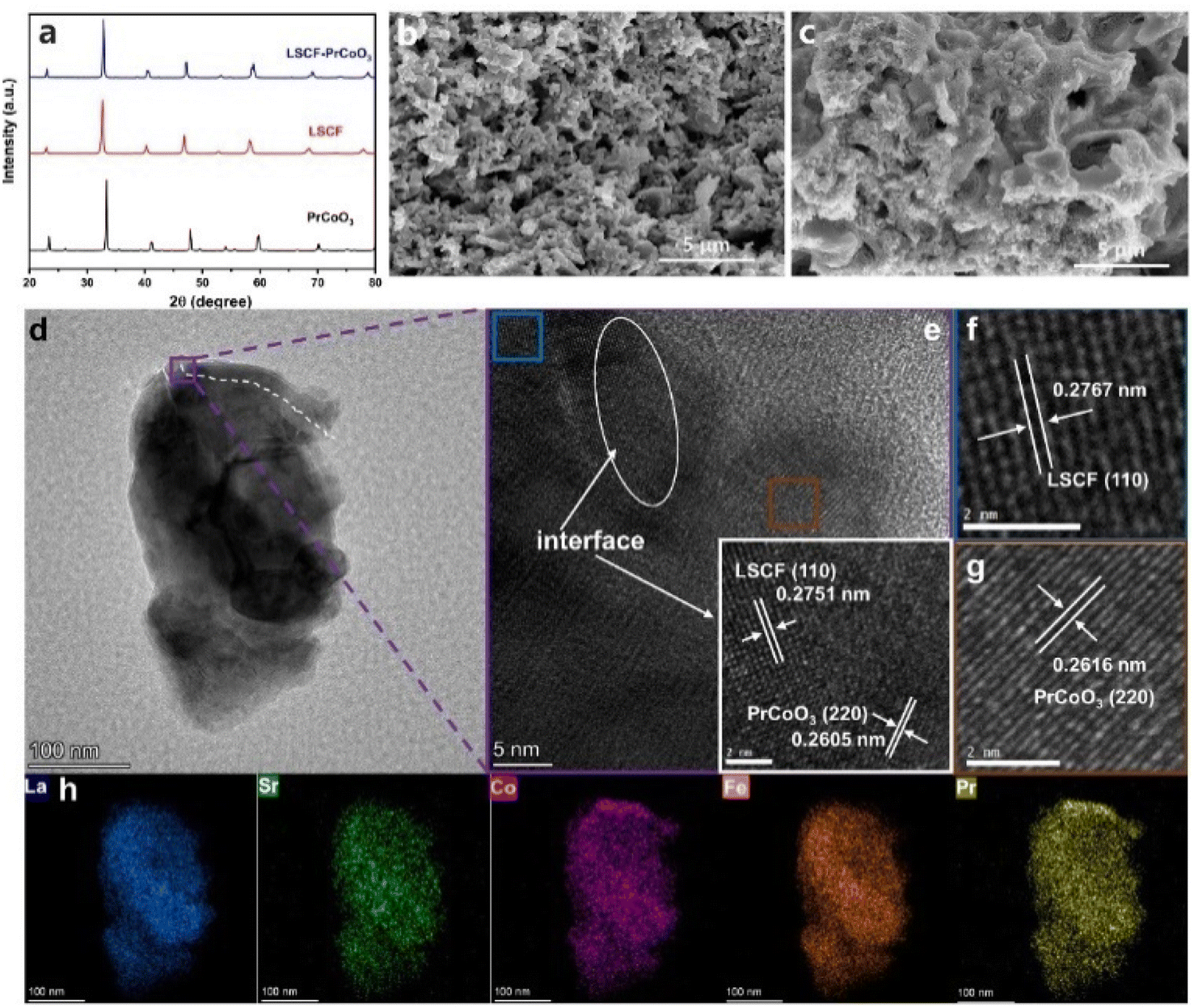 | ||
| Fig. 1 (a) XRD patterns of the as-prepared LSCF and PCO, as well as the PCO–LSCF mixture after heat treatment at 1250 °C for 4 h. (b) Microstructure of the LSCF air electrode. (c) Microstructure of the PCO–LSCF air electrode. (d and e) HRTEM images of particles stripped from the PCO–LSCF electrode. (f) Lattice fringe in the blue region of (e). (g) Lattice fringe in the orange region of (e). (h) EDS mapping of the purple squared region in (d). | ||
Compared to the smooth LSCF scaffold (Fig. 1b), the PCO–LSCF surface presents a uniform PCO nano-film coating (Fig. 1c). To further verify the PCO's distribution on the LSCF scaffold's surface, HRTEM analysis on particles stripped from the PCO–LSCF scaffold was conducted, as shown in Fig. 1d–h. In the EDS mapping (as shown in Fig. 1h), there is a clear enrichment of Pr and Co elements on the particle's top surface, with weaker signals of La, Sr, and Fe elements, providing strong evidence of PCO's presence. Moreover, PCO is uniformly distributed around the periphery of the LSCF particles. Based on the elemental distribution map, the PCO nanocoating on the particle in Fig. 1d can be roughly outlined. In the HRTEM image shown in Fig. 1e, the difference in interplanar spacing around the outline can be clearly seen. The white circled area shows an obvious interlacing of two types of crystal planes, with the measured interplanar spacings of 0.2751 and 0.2605 nm, corresponding to the LSCF (110) crystal plane (2.739 Å, PDF # 89-5720) and the PCO (220) crystal plane (2.676 Å, PDF # 25-1069), respectively. Thus, the white circled area can be determined to cover the interface between PCO and LSCF, as indicated by the white outline in Fig. 1d, which crosses this area. The blue squared area on the left side of the white circled outline, with an interplanar spacing of 0.2767 nm, is almost identical to the LSCF (110) crystal plane, indicating that this area can be identified as LSCF. Similarly, the orange squared area can be identified as PCO. These TEM results demonstrate that the PCO nano-catalyst coating can be achieved on the surface of the LSCF scaffold through solution infiltration.
3.2 k chem and Dchem of PCO–LSCF
The ORR/OER of PCC air electrodes necessitate the transport and transfer of e−, H+, and O2−, underscoring the importance of the high oxygen surface exchange coefficient (kchem) and oxygen bulk diffusion coefficient (Dchem) for their ORR/OER activity. The electrical conductivity relaxation (ECR) method was employed to assess the kchem and Dchem of both LSCF and PCO–LSCF, as shown in Fig. 2 and S1.† Notably, at various temperatures, the kchem and Dchem values of PCO–LSCF were significantly superior to those of LSCF. Specifically, at 650 °C, the kchem and Dchem values of PCO–LSCF reached 3.10 × 10⁻⁴ cm s−1 and 3.54 × 10⁻⁵ cm2 s−1, respectively, compared with the values of 6.59 × 10⁻⁵ cm s−1 for kchem and 6.59 × 10⁻⁶ cm2 s−1 for Dchem of LSCF, respectively. The increased kchem and Dchem values of PCO–LSCF could be attributed to the extremely high kchem and Dchem values of PCO, as shown in Fig. S1.† Upon dissociation of oxygen molecules into oxide ions on the PCO surface, these ions traverse the thin PCO layer. Due to PCO's inherently high Dchem value, it effectively contributes to the increase of the Dchem value for the PCO–LSCF electrode. Furthermore, PCO–LSCF demonstrated outstanding oxygen surface exchange and bulk diffusion properties among different air electrodes reported in the literature, as detailed in Table S1.† These findings demonstrate that the PCO–LSCF air electrode possesses high kinetics for the surface oxygen exchange process, which is a pre-requisite for promising ORR/OER catalytic activity. | ||
| Fig. 2 k chem and Dchem of LSCF and PCO–LSCF obtained from the ECR measurement at 650–750 °C. | ||
3.3 Electrochemical performance of symmetrical cells
To assess the catalytic activity of the air electrodes, EIS tests were performed on symmetric cells under humid air (3% H2O) conditions. Applying a PCO nanocoating on the surface of the LSCF led to a notable reduction in the polarization resistance (Rp), as shown in Fig. 3a and b. Specifically, at 700, 650, 600, and 550 °C, the Rp values were 0.062, 0.139, 0.320, and 0.786 Ω cm2 for PCO–LSCF, much lower than those for LSCF under similar testing conditions, 0.082, 0.200, 0.551, and 1.811 Ω cm2, respectively. Fig. 3c presents the Arrhenius plots for the polarization resistances of the PCO–LSCF and LSCF air electrodes, illustrating the temperature dependence of their performances. The calculated activation energy for the PCO–LSCF air electrode is 1.17 eV, markedly lower than that of the LSCF electrode at 1.42 eV. This lower activation energy suggests that the performance of the PCO–LSCF air electrode is less sensitive to temperature variations, potentially enabling more stable operation under varying thermal conditions. To gain some insight into the reaction kinetics of the air electrode, EIS data obtained at 600 °C were analysed using the distribution of relaxation time (DRT) method. This DRT analysis, as illustrated in Fig. 3d, allowed for the electrochemical processes within the air electrode to be deconvoluted into several distinct peaks. These peaks were categorized into three frequency regions: low frequency (P1), medium frequency (P2), and high frequency (P3).29 P1 can be associated with the gas diffusion process, P2 with the gas surface exchange and ionic bulk diffusion, and P3 with the charge transfer process.30 Notably, the areas of P2 and P3 for PCO–LSCF exhibited a significant reduction when compared to those of LSCF. This reduction is attributed to the enhanced oxygen surface exchange and oxygen ion bulk diffusion facilitated by the introduction of the PCO nanocoating. Such enhancements are closely linked to the elevated kchem and Dchem values of PCO–LSCF. | ||
| Fig. 3 (a) EIS of the LSCF symmetric cell in humid air (3% H2O) at 550–700 °C. (b) EIS of the PCO–LSCF symmetric cell in humid air (3% H2O) at 550–700 °C. (c) Ln(Rp) vs. 1/T curves of the LSCF and PCO–LSCF air electrodes. (d) DRT analysis of EIS for LSCF and PCO–LSCF at 600 °C. | ||
3.4 Electrochemical performance of single cells
The catalytic activity of LSCF is significantly enhanced with the introduction of a PCO nanocoating, as further evidenced in PCC single cells. As illustrated in Fig. 4a–c, the cross-sectional microstructure of the single cell reveals a porous electrode and a dense electrolyte layer of about 12 μm in thickness, with a well bonded electrode/electrolyte interface that facilitates charge transfer. Single cells with the LSCF electrode showed peak power densities of 1.01, 0.706, and 0.468 W cm−2 at 650, 600, and 550 °C, respectively (Fig. 4d). The introduction of the PCO nanocoating on the surface of LSCF has led to increased peak power densities of 1.14, 0.803, and 0.526 W cm−2 at 650, 600, and 550 °C (Fig. 4e), primarily attributed to the reduced Rp value (Fig. S2†). When compared to other advanced PCFC air electrodes reported in the literature, our PCO–LSCF electrode showcases superior catalytic activity, as demonstrated by Fig. 4f and Table 1.31–38 | ||
| Fig. 4 (a) Cross-sectional microstructure of the single cell. (b) Ni–BaZr0.4Ce0.4Y0.1Yb0.1O3−δ interfacial microstructure. (c) PCO–LSCF/BZCYYb interfacial microstructure; I–V–P curves of PCFCs with LSCF (d) and PCO–LSCF (e) air electrodes. (f) Comparison of PCFC performance using the PCO–LSCF air electrode with those reported in the literature. I–V curves of PCECs with LSCF (g) and PCO–LSCF (h) air electrodes. (i) Comparison of PCEC performance using the PCO–LSCF air electrode with those reported in the literature. | ||
| Air electrode | Electrolyte | Air electrode environment | T (°C) | PPD (W cm−2) | Ref. |
|---|---|---|---|---|---|
| a BZCYYb1711: BaZr0.1Ce0.7Y0.1Yb0.1O3−δ; BZCYYb4411: BaZr0.4Ce0.4Y0.1Yb0.1O3−δ. | |||||
| NdBa0.8Ca0.2Co2O5+δ | BZCYYb4411 (15 μm) | 3% H2O–97% air | 600 | 0.65 | 30 |
| Zn-doped Ba0.95La0.05FeO3−δ–BZCYYb1711 | BZCYYb1711 (10 μm) | Air | 600 | 0.286 | 31 |
| Nd(Ba0.4Sr0.4Ca0.2)Co1.6Fe0.4O5+δ–BZCYYb1711 | BZCYYb1711 (13 μm) | Air | 600 | 0.218 | 32 |
| LSCF–BZCYYb1711 | BZCYYb1711 (14 μm) | 3% H2O–97% air | 600 | 0.57 | 33 |
| PrBaCo1.6Fe0.2Nb0.2O5+δ | BZCYYb1711 (10 μm) | 3% H2O–97% air | 600 | 0.723 | 34 |
| Ba0.5Sr0.5(Co0.7Fe0.3)0.6875W0.3125O3−δ | BZCYYb1711 (15 μm) | 3% H2O–97% air | 600 | 0.582 | 35 |
| NdBa0.5Sr0.5Co1.5Fe0.5O5+δ | BZCYYb1711 (15 μm) | 3% H2O–97% air | 600 | 0.69 | 36 |
| Pr0.1Ce0.9O2+δ–PrBaCo2O5+δ | BZCYYb1711 (15 μm) | 3% H2O–97% air | 600 | 0.87 | 37 |
| PCO–LSCF | BZCYYb4411 (12 μm) | 3% H2O–97% air | 600 | 0.706 | This work |
PCECs with the PCO–LSCF air electrode achieved current densities of 2.04, 1.22, and 0.585 A cm−2 at 650, 600, and 550 °C, respectively, as shown in Fig. 4h. This contrasts with the performance of PCECs with the LSCF air electrode, which only reached current densities of 1.85, 1.14, and 0.55 A cm−2 under similar testing conditions (Fig. 4g). Tables S1 and S2† present the current densities at various cell voltages for the single cells, illustrating the performance disparities between LSCF and PCO–LSCF air electrodes. The PCO nanocoating on the surface of LSCF has led to a significant reduction in the Rp value of PCECs (Fig. S3†), and the PCO–LSCF air electrode has demonstrated outstanding performance compared to other advanced PCEC air electrodes, as shown in Fig. 4i and Table 2.35,39–44
| Air electrode | Electrolyte | Air electrode environment | T (°C) | Current density @ 1.3 V (A cm−2) | Ref. |
|---|---|---|---|---|---|
| NdBa0.5Sr0.5Co1.5Fe0.5O5+δ–BZCYYb4411 | BZCYYb4411 (14.7 μm) | 10% H2O–90% air | 600 | −0.75 | 38 |
| PrBa0.5Sr0.5Co1.5Fe0.5O5+δ | BaZr0.8Y0.2O3−δ (15 μm) | — | 600 | −0.903 | 39 |
| 3D-PrNi0.5Co0.5O3−δ | BZCYYb4411 (10 μm) | 10% H2O–90% air | 600 | −1.18 | 40 |
| BaGd0.8La0.2Co2O6−δ | BaZr0.2Ce0.7Y0.1O3−δ (25 μm) | — | 600 | −0.97 | 41 |
| La1.2Sr0.8NiO4−δ–BaCe0.68Zr0.1Y0.1Yb0.1Cu0.02O3−δ | BaCe0.68Zr0.1Y0.1Yb0.1Cu0.02O3−δ (13 μm) | 20% H2O–80% air | 600 | −1.04 | 42 |
| PrBa0.5Sr0.5Co1.5Fe0.5O5+δ–BZCYYb1711 | BZCYYb1711 (15 μm) | 40% H2O–60% air | 650 | −0.743 | 43 |
| PrBaCo1.6Fe0.2Nb0.2O5+δ | BZCYYb1711 (10 μm) | 3% H2O–97% air | 600 | −1.036 | 34 |
| PCO–LSCF | BZCYYb4411 (12 μm) | 30% H2O–70% air | 600 | −1.18 | This work |
During PCEC performance testing, the air electrode atmosphere was air containing 30% H2O. Interestingly, variations in water vapor pressure (pH2O) within the air electrode appeared to have minimal impact on the current density of the electrolysis cell. Evidence from Fig. S4† indicates that, even as pH2O ranged from 3% to 30%, the current density at 1.3 V maintained a steady level of about 1.4 A cm−2 at 600 °C. An increase in pH2O in the air electrode was observed to reduce the OCV (from 1.038 V to 1.032 V) of the PCEC single cell, while simultaneously causing an increase in the Rp value (Fig. S4†). The concurrent effects of these changes in pH2O do not markedly influence the electrolysis performance. Following this, a comprehensive evaluation of the performance of LSCF symmetric cells subjected to different pH2O was conducted (Fig. S5 and S6†). A rise in pH2O consistently results in an increase in the Rp value of the air electrode. While humid conditions promote the formation of protonic defects and enhance proton migration, the excessive absorption of H2O diminishes the oxygen adsorption on the surface of the air electrode, consequently leading to elevated Rp. Differential EIS analysis (Fig. S7†) revealed that pH2O predominantly impacts the P1 and P2 processes, namely the gas diffusion and the oxygen surface exchange processes. It is also noteworthy that increasing pH2O within the air electrode significantly boosts the Faraday efficiency of the PCEC single cell.21,45,46 Consequently, PCECs are inclined to operate under conditions of high pH2O to optimize electrolysis efficiency. Nevertheless, the durability of LSCF under conditions of high-temperature and high-humidity remains a concern.
3.5 Long-term stability and steam tolerance of PCO–LSCF
At 650 °C and under 30% H2O conditions, short-term tests were conducted on both LSCF and PCO–LSCF symmetric cells, with the Rp values recorded at intervals of several hours, as shown in Fig. 5a. During a 65 hour test period, the Rp value of LSCF sharply increased from 0.35 to 1.34 Ω cm2, revealing a degradation rate of 0.015 Ω cm2 h−1, indicating LSCF's instability in a high-temperature and high-humidity environment. In contrast, the PCO–LSCF cell showed significantly improved steam tolerance; its Rp value increased from 0.34 to 0.49 Ω cm2 within 48 h, with a much lower degradation rate of 0.003 Ω cm2 h−1. This comparison underscores the enhanced stability of PCO–LSCF under the same testing conditions. To understand the reasons for the enhanced steam tolerance of PCO–LSCF, LSCF and PCO–LSCF powders were subjected to a heat treatment at 750 °C for 72 h in a 50% H2O–50% air atmosphere. The subsequent XRD characterization revealed that LSCF exhibited a small amount of impurity phases (SrFeO2.71, La3Co3O8, and La0.6Sr0.4FeO3) following the hydrolysis treatment (Fig. S8†). Additionally, phase instability was observed in the three strong diffraction peaks between 55 and 80°. These findings further confirm LSCF's instability under high-temperature and high-humidity environments, which is consistent with the observed sharp increase in the Rp value of the LSCF symmetric cells. In contrast, there are no observable impurity peaks for the PCO–LSCF powder after the hydrolysis treatment, highlighting the enhanced chemical stability of PCO–LSCF, which effectively prevents direct contact between LSCF and steam, thereby significantly enhancing the steam tolerance of LSCF. | ||
| Fig. 5 (a) Rp variation over time for LSCF and PCO–LSCF symmetric cells in the air containing 30% H2O at 650 °C. (b) Durability test of a PCEC single cell with a PCO–LSCF electrode at 600 °C (3% H2O, J = −0.5 A cm−2). (c) Durability test of a PCEC single cell with a PCO–LSCF electrode at 600 °C (30% H2O, J = −0.5 A cm−2). (d) Variation of current density over time in the PCEC–PCFC cycling test. | ||
To further verify the steam tolerance of PCO–LSCF, long-term stability tests were carried out on PCECs with the PCO–LSCF air electrode. During a 1128 hour test at 600 °C with a steam concentration of 3% H2O in the air electrode and a current density of −0.5 A cm−2 (Fig. 5b), the single cell with a PCO–LSCF air electrode demonstrated remarkable stability, with no observable voltage degradation in 1128 h testing. This stability was maintained even when the steam concentration in the air electrode was increased to 30%, highlighting the robustness of the PCO–LSCF electrode (Fig. 5c). Furthermore, in a 128 hour PCFC/PCEC cycling test at 600 °C, which involved switching the cell between 0.7 V and 1.3 V for 32 cycles (Fig. 5d), there is very stable cell performance, indicating the excellent cycling stability of the PCO–LSCF air electrode. In contrast, the LSCF air electrode suffered notable performance degradation under similar conditions. Short-term electrolysis testing at 3% H2O led to a noticeable voltage increase within just 60 h, with a degradation rate reaching 0.019% h−1 (Fig. S9a†). EIS further highlighted the stability of the cell's ohmic impedance and the gradual increase in polarization impedance over time (Fig. S9b†), suggesting that LSCF's hydrolysis was primarily responsible for the electrolysis cell's performance degradation. The corrosion of the LSCF scaffold was visibly confirmed by comparing its microstructure before and after the short-term electrolysis test (Fig. S10†).
As previously mentioned, high-temperature and high-humidity atmospheres can exacerbate Sr segregation on the surface of LSCF. These segregated Sr species react with H2O molecules in the PCC air electrode atmosphere, leading to structural damage in the LSCF phase. The stability of the LSCF air electrode is compromised in high-temperature and high-humidity atmospheres, even with a low steam concentration of 3%. Therefore, direct use of LSCF as a PCC air electrode is not advisable. Several studies have indicated that applying a nanocoating on the surface of the LSCF scaffold can mitigate Sr segregation.47–49 In this study, the introduced PCO nanocoating can also partially inhibit Sr segregation in LSCF, significantly enhancing the electrode's stability. The application of a nano-coating on the LSCF scaffold results in an elevated formation energy of oxygen vacancies, consequently diminishing their concentration on the surface.50,51 This reduction in surface oxygen vacancies attenuates the electrostatic interactions between the positively charged surface oxygen vacancies and the negatively charged defect SrLa′, thus effectively mitigating the surface segregation of Sr. Therefore, the introduction of a PCO coating contributes positively to the inhibition of Sr segregation on LSCF surfaces, subsequently diminishing the chemical interaction between segregated Sr and H2O. Additionally, PCO can physically isolate H2O molecules from the LSCF scaffold, thereby improving the electrode's steam tolerance. It is worth noting that the PCO nanocoating introduced by solution infiltration may not entirely cover the LSCF scaffold (Fig. 1c). Consequently, the PCO nanocoating may not completely prevent the phase decomposition of the LSCF scaffold induced by high humidity. However, with the support of the PCO nanocoating, the Sr segregation and the adsorption of H2O molecules on the LSCF surface can be effectively suppressed. Consequently, PCO–LSCF demonstrates significantly boosted steam tolerance and durability.
4 Conclusions
In summary, a PCO nanocoating was successfully applied on the surface of the LSCF scaffold through solution infiltration, notably enhancing its catalytic activity and significantly improving its stability under high-temperature and high-humidity environments. Outstanding cell performance has been achieved using the PCO coated LSCF air electrode, reaching a peak cell output power density of 1.14 W cm−2 in fuel cell mode and a current density of 2.04 A cm−2 at 1.3 V in electrolysis mode at 650 °C. The remarkable improvement in the electrochemical catalytic activity of the PCO coated LSCF air electrode is primarily due to the enhanced kchem and Dchem facilitated by the PCO nanocoating. Moreover, the PCO coated LSCF air electrode demonstrated excellent stability in challenging high-temperature and high-humidity environments, maintaining stable cell performance for 1128 h in electrolysis mode. This work demonstrates the high promise of PCO surface-modified LSCF as a high-performance air electrode with excellent stability in high steam and high temperature environments.Data availability
The authors confirm that the data supporting the findings of this study are available within the article and its ESI.†Conflicts of interest
The authors declare that they have no known competing financial interests or personal relationships that could have influenced the work report in this paper.Acknowledgements
We acknowledge the financial support by the National Natural Science Foundation of China (52102279), the Natural Science Foundation of Shandong Province (ZR2021QE283) and the U.S. National Science Foundation (1832809).Notes and references
- A. Hauch, R. Küngas, P. Blennow, A. B. Hansen, J. B. Hansen, B. V. Mathiesen and M. B. Mogensen, Science, 2020, 370, eaba6118 CrossRef CAS PubMed.
- D. J. Brett, A. Atkinson, N. P. Brandon and S. J. Skinner, Chem. Soc. Rev., 2008, 37, 1568–1578 RSC.
- A. Ndubuisi, S. Abouali, K. Singh and V. Thangadurai, J. Mater. Chem. A, 2022, 10, 2196–2227 RSC.
- D. Kim, T. K. Lee, S. Han, Y. Jung, D. G. Lee, M. Choi and W. Lee, Mater. Today Energy, 2023, 36, 101365 CrossRef CAS.
- Y. Meng, J. Gao, Z. Zhao, J. Amoroso, J. Tong and K. S. Brinkman, J. Mater. Sci., 2019, 54, 9291–9312 CrossRef CAS.
- L. Lei, J. Zhang, Z. Yuan, J. Liu, M. Ni and F. Chen, Adv. Funct. Mater., 2019, 29, 1903805 CrossRef.
- J. Cao, Y. Ji and Z. Shao, Energy Environ. Sci., 2022, 15, 2200–2232 RSC.
- F. Liu, D. Ding and C. Duan, Adv. Sci., 2023, 10, 2206478 CrossRef CAS PubMed.
- Y. Zhou, W. Zhang, N. Kane, Z. Luo, K. Pei, K. Sasaki, Y. Choi, Y. Chen, D. Ding and M. Liu, Adv. Funct. Mater., 2021, 31, 2105386 CrossRef CAS.
- Y. Niu, Y. Zhou, W. Zhang, Y. Zhang, C. Evans, Z. Luo, N. Kane, Y. Ding, Y. Chen and X. Guo, Adv. Energy Mater., 2022, 12, 2103783 CrossRef CAS.
- Y. Niu, Y. Zhou, W. Lv, Y. Chen, Y. Zhang, W. Zhang, Z. Luo, N. Kane, Y. Ding and L. Soule, Adv. Funct. Mater., 2021, 31, 2100034 CrossRef CAS.
- L. Li, J. Zhou, Z. Hu, S. Choi, G. Kim, J.-Q. Wang and L. Zhang, J. Phys. Chem. Lett., 2021, 12, 11503–11510 CrossRef CAS PubMed.
- R. Glöckner, M. Islam and T. Norby, Solid State Ionics, 1999, 122, 145–156 CrossRef.
- B. Koo, K. Kim, J. K. Kim, H. Kwon, J. W. Han and W. Jung, Joule, 2018, 2, 1476–1499 CrossRef CAS.
- R. Liu, S. Kim, S. Taniguchi, T. Oshima, Y. Shiratori, K. Ito and K. Sasaki, J. Power Sources, 2011, 196, 7090–7096 CrossRef CAS.
- M. Niania, R. Podor, T. B. Britton, C. Li, S. J. Cooper, N. Svetkov, S. Skinner and J. Kilner, J. Mater. Chem. A, 2018, 6, 14120–14135 RSC.
- Z. Wang, X. Miao, X. Ye and Z. Wen, ACS Appl. Mater. Interfaces, 2023, 15, 45035–45044 CrossRef CAS PubMed.
- Y. Chen, Y. Choi, S. Yoo, Y. Ding, R. Yan, K. Pei, C. Qu, L. Zhang, I. Chang and B. Zhao, Joule, 2018, 2, 938–949 CrossRef CAS.
- Z. Chen, L. Jiang, S. He, C. Guan, Y. Zou, Z. Yue, N. Ai, Y. Shao and K. Chen, Appl. Catal., B, 2022, 305, 121056 CrossRef CAS.
- Y. Zhou, E. Liu, Y. Chen, Y. Liu, L. Zhang, W. Zhang, Z. Luo, N. Kane, B. Zhao and L. Soule, ACS Energy Lett., 2021, 6, 1511–1520 CrossRef CAS.
- T. Hu, F. Zhu, J. Xia, F. He, Z. Du, Y. Zhou, Y. Liu, H. Wang and Y. Chen, Adv. Funct. Mater., 2023, 33, 2305567 CrossRef CAS.
- Z. Liu, Y. Lin, H. Nie, D. Liu, Y. Li, X. Zhao, T. Li, G. Yang, Y. Sun and Y. Zhu, Adv. Funct. Mater., 2024, 34, 2311140 CrossRef CAS.
- Y. Li, W. Zhang, Y. Zheng, J. Chen, B. Yu, Y. Chen and M. Liu, Chem. Soc. Rev., 2017, 46, 6345–6378 RSC.
- Y. Chen, W. Zhou, D. Ding, M. Liu, F. Ciucci, M. Tade and Z. Shao, Adv. Energy Mater., 2015, 5, 1500537 CrossRef.
- H. Wang, G. Li, X. Guan, M. Zhao and L. Li, Phys. Chem. Chem. Phys., 2011, 13, 17775–17784 RSC.
- R. Thakur, R. K. Thakur and N. Gaur, J. Alloys Compd., 2016, 661, 257–267 CrossRef CAS.
- Q. Liu, R. Li, W. Feng, J. Li, X. Zhang, H. Lv, Y. Shen, Y. Song, G. Wang and X. Bao, ACS Appl. Energy Mater., 2022, 5, 11604–11612 CrossRef CAS.
- P. Qiu, L. Wu, K. Cheng, S. Wu, H. Qi, C. Xiong and B. Tu, Int. J. Hydrogen Energy, 2023, 48, 27805–27813 CrossRef CAS.
- M. Plekhanov, A. Kuzmin, E. Tropin, D. Korolev and M. Ananyev, J. Power Sources, 2020, 449, 227476 CrossRef CAS.
- Z. Liu, Y. Chen, G. Yang, M. Yang, R. Ji, Y. Song, R. Ran, W. Zhou and Z. Shao, Appl. Catal., B, 2022, 319, 121929 CrossRef CAS.
- Y. Wang, H. Zhang, J. Cao, K. Xu, K. Pei and Y. Chen, J. Power Sources, 2022, 524, 231101 CrossRef CAS.
- J. Jing, Z. Lei, Z. Zheng, H. Wang, Z. Yang and S. Peng, Int. J. Hydrogen Energy, 2022, 47, 35449–35457 CrossRef CAS.
- J. Chen, J. Li, L. Jia, I. Moussa, B. Chi, J. Pu and J. Li, J. Power Sources, 2019, 428, 13–19 CrossRef CAS.
- H. Shimada, Y. Yamaguchi, H. Sumi and Y. Mizutani, Ceram. Int., 2021, 47, 16358–16362 CrossRef CAS.
- K. Xu, H. Zhang, Y. Xu, F. He, Y. Zhou, Y. Pan, J. Ma, B. Zhao, W. Yuan and Y. Chen, Adv. Funct. Mater., 2022, 32, 2110998 CrossRef CAS.
- D. Hu, J. Kim, H. Niu, L. M. Daniels, T. D. Manning, R. Chen, B. Liu, R. Feetham, J. B. Claridge and M. J. Rosseinsky, J. Mater. Chem. A, 2022, 10, 2559–2566 RSC.
- J. Kim, S. Sengodan, G. Kwon, D. Ding, J. Shin, M. Liu and G. Kim, ChemSusChem, 2014, 7, 2811–2815 CrossRef CAS PubMed.
- K. Pei, S. Luo, F. He, J. Arbiol, Y. Xu, F. Zhu, Y. Wang and Y. Chen, Appl. Catal., B, 2023, 330, 122601 CrossRef CAS.
- J. Kim, A. Jun, O. Gwon, S. Yoo, M. Liu, J. Shin, T.-H. Lim and G. Kim, Nano Energy, 2018, 44, 121–126 CrossRef CAS.
- C. Duan, R. Kee, H. Zhu, N. Sullivan, L. Zhu, L. Bian, D. Jennings and R. O'Hayre, Nat. Energy, 2019, 4, 230–240 CrossRef CAS.
- H. Ding, W. Wu, C. Jiang, Y. Ding, W. Bian, B. Hu, P. Singh, C. J. Orme, L. Wang and Y. Zhang, Nat. Commun., 2020, 11, 1907 CrossRef CAS PubMed.
- E. Vøllestad, R. Strandbakke, M. Tarach, D. Catalán-Martínez, M.-L. Fontaine, D. Beeaff, D. R. Clark, J. M. Serra and T. Norby, Nat. Mater., 2019, 18, 752–759 CrossRef PubMed.
- C. Sun, S. Yang, Y. Lu, J. Wen, X. Ye and Z. Wen, J. Power Sources, 2020, 449, 227498 CrossRef CAS.
- H. Bai, Y. Zhang, J. Chu, Q. Zhou, H. Lan and J. Zhou, ACS Appl. Mater. Interfaces, 2023, 15, 38581–38591 CrossRef CAS PubMed.
- F. He, S. Liu, T. Wu, M. Yang, W. Li, G. Yang, F. Zhu, H. Zhang, K. Pei and Y. Chen, Adv. Funct. Mater., 2022, 32, 2206756 CrossRef CAS.
- F. He, Y. Zhou, T. Hu, Y. Xu, M. Hou, F. Zhu, D. Liu, H. Zhang, K. Xu and M. Liu, Adv. Mater., 2023, 35, 2209469 CrossRef CAS PubMed.
- J. Li, X. Zhou, C. Wu, L. Zhao, B. Dong, S. Wang and B. Chi, Chem. Eng. J., 2022, 438, 135446 CrossRef CAS.
- D. Zeng, K. Xu, F. Zhu and Y. Chen, Int. J. Hydrogen Energy, 2023, 48, 23992–24001 CrossRef CAS.
- Y. Yu, K. F. Ludwig, J. C. Woicik, S. Gopalan, U. B. Pal, T. C. Kaspar and S. N. Basu, ACS Appl. Mater. Interfaces, 2016, 8, 26704–26711 CrossRef CAS PubMed.
- J. Huang, F. Liang, S. Zhao, L. Zhao, N. Ai, S. P. Jiang, X. Wang, H. Fang, Y. Luo and K. Chen, Adv. Funct. Mater., 2024, 34, 2310402 CrossRef CAS.
- J. Huang, Q. Liu, L. Zhao, N. Ai, X. Wang, Y. Shao, C. Guan, H. Fang, Y. Luo and K. Chen, Appl. Catal., B, 2023, 321, 122080 CrossRef CAS.
Footnote |
| † Electronic supplementary information (ESI) available. See DOI: https://doi.org/10.1039/d4ta03706e |
| This journal is © The Royal Society of Chemistry 2024 |