DOI:
10.1039/D4TA02944E
(Paper)
J. Mater. Chem. A, 2024,
12, 24357-24369
A 3D-printed fully biocompatible supercapacitor†
Received
28th April 2024
, Accepted 1st August 2024
First published on 1st August 2024
Abstract
A fully biocompatible supercapacitor was fabricated utilizing dopamine-grafted activated carbon-based (DPBAC) electrode material along with a choline chloride–urea-based eco-friendly Reline deep eutectic solvent electrolyte. The current collector (graphite ink), electrode (DPBAC ink), and electrolyte (Reline) were 3D printed using the optimized printing parameters tailored specifically for the Piezo jet dispenser printing tool. Dopamine was grafted on commercially available (YP-80 F) bare activated carbon (BAC) using the π–π stacking method. Thermogravimetric analysis, Raman spectroscopy, Brunauer–Emmett–Teller method and X-ray photoelectron spectroscopy results confirmed the grafting of dopamine on BAC. 3D printed devices (size of 50 mm × 50 mm × 0.5 mm) were fabricated using DPBAC and BAC-based electrode materials to study the electrochemical performance. The DPBAC supercapacitor displayed a specific capacitance of 39 F g−1 which was comparatively higher than that of BAC (23 F g−1) at a current density of 0.2 A g−1, demonstrating the contribution of the redox reaction of the grafted dopamine molecule. The developed 3D-printed fully biocompatible supercapacitors (3DPBSC) demonstrate an outstanding specific capacitance of 96 F g−1 at a scan rate of 1 mV s−1 which surpasses the previously reported state-of-the-art performance (25.6 F g−1 at a scan rate of 1 mV s−1 for 1.2 V for fully 3D printed and disposable paper supercapacitors). Moreover, 3DPBSC exhibited a maximum energy density of 22 W h kg−1 at a power density of 1835 W kg−1 within a device voltage range from 0 to 2.0 V. These results highlight the promising potential of the fabricated 3DPBSC as flexible and sustainable supercapacitors for applications in low-power wireless sensors.
1 Introduction
The rapid advancement of the Internet of Things and wearable electronics has accelerated the unquenchable demand for affordable energy storage systems that seamlessly integrate with their intended applications. Supercapacitors (SCs), also known as electrochemical capacitors, have garnered significant attention for their exceptional power density, extended cycle life, and unmatched charge–discharge speed when compared to traditional batteries and capacitors.1,2 The growing focus on sustainable energy technologies has spurred recent developments in the exploration of eco-friendly materials for SCs. Furthermore, electrodes assume a pivotal role in determining the electrochemical performance of energy storage devices. Enhancing their performance involves various approaches, including material optimization, the development of novel energy storage devices, the incorporation of chemical additives, and the implementation of advanced electrode architecture design. Yet, conventional electrode manufacturing techniques like the two-dimensional (2D) slurry-coating method present limitations in realizing electrodes with advanced architecture.3 The advent of additive manufacturing has ushered in the era of advanced electrode architecture design, focusing squarely on enhancing the performance of energy storage devices. This cutting-edge approach, also known as three-dimensional (3D) printing, stands as a rapidly expanding manufacturing technique offering remarkable freedom in structural design.4 Through the synergy of computer-aided design, 3D printing empowers the realization of virtually any electrode geometry. Furthermore, the highly automated manufacturing process and straightforward synthesis pathways substantially reduce the costs associated with commercial electrode production, setting it apart from traditional manufacturing methods.
Many 3D-printed SCs documented thus far have relied on graphene, graphite, carbon nanotubes, activated carbon, polyaniline, poly(3,4-ethylenedioxythiophene) polystyrene sulfonate (PEDOT: PSS), and MXenes, as their primary electrode material.5 It is also widely known that activated carbon (AC) stands as the sole electrode material for SCs to have achieved commercial success, primarily owing to their exceptional attributes such as high surface area, adjustable pore size distribution, and cost-effectiveness when compared to alternative carbon and metal oxide materials.1,6 An intriguing opportunity lies in the exploration of composites generated through the incorporation of biodegradable pseudocapacitive materials via doping or grafting onto AC. This approach capitalizes on the advantages of two distinct charge storage mechanisms, making it well-suited for 3D printing, while simultaneously addressing dual concerns related to energy performance and sustainability considerations. Reversible redox activity shows that organic molecules, which are renewable resources and economically affordable, are highly regarded as electrode materials with great potential for pseudocapacitance. Quinones and their derivatives exhibit remarkable redox activity, electrochemical reversibility, and affordability, making them highly promising candidates for pseudocapacitors. Hence, researchers have devoted more attention to synthesizing composite materials by combining carbon-quinone materials.7 For example, Liu et al.8 studied the electrochemical performance of a redox-active tetramino-benzoquinone with multi-walled carbon nanotube-based composite (TABQ-MWCNTs) synthesized via immobilization of the redox-active organic molecule TABQ onto hydroxylated MWCNTs through noncovalent interactions, including π–π stacking and H-bonding. In comparison to the specific capacitance of bare MWCNTs (17 F g−1), the composite exhibits an impressive high specific capacitance of 463 F g−1 at 1 A g−1. Similarly, Pognon and co-worker9 reported that anthraquinone modified activated carbon demonstrates twice the capacitance (195 F g−1) compared to unmodified carbon (100 F g−1) due to the significant contribution of the redox reaction facilitated by grafting anthraquinone molecules. The existing literature provides ample evidence that the modification with quinone is a highly effective approach for enhancing the capacitive performance of carbonaceous materials.10,11 Aside from a recently published study by Purkait et al. 2020 on the electrochemical performance of reduced graphene oxide networks functionalized with environmentally friendly dopamine,12 dopamine-grafted activated carbon-based composite studies for SC application are still missing.
Furthermore, exploring novel and eco-friendly electrolytes for SCs is crucial for advancing technology in terms of performance, safety, sustainability, and regulatory compliance, while also meeting growing environmental and market demands.13–15 Considering these factors, Reline deep eutectic solvents are a suitable choice due to their impressive electrochemical stability, environmental friendliness, and cost-effectiveness, which suggest the potential for improved device performance. The unique advantage of Reline is its ability to enable the creation of energy cells under normal atmospheric conditions, unlike energy cells that depend on organic electrolytes and require glove-box setups for ionic liquids.16 Research has demonstrated that the choline chloride–urea eco-friendly Reline electrolyte exhibits outstanding cycle stability at 2.2 V, coupled with remarkable capacitance retention. It's worth noting that there have been no prior studies on 3D printing of the Reline electrolyte. 3D printing of Reline offers significant advantages over conventional loading techniques. Conventional methods involve immersing electrodes and separators in the electrolyte for 24 h and the high viscosity of Reline requires vertically holding electrodes and separators to efficiently remove excess electrolyte before assembly. By utilizing 3D printing techniques, precise loading of Reline onto the active areas of electrodes is achieved without the need for extended waiting periods. Moreover, optimizing the electrochemical performance of devices is possible through repeated cycles of electrolyte loading. Consequently, this research signifies the inaugural instance of printing the Reline electrolyte, thereby paving the way for enhanced electrochemical applications. Employing a dopamine grafted BAC and choline chloride–urea eco-friendly Reline electrolyte holds promise as a viable electrode and electrolyte material suitable for 3D printing, with a dual focus on both energy performance and sustainability considerations.
Here, we are reporting the electrochemical properties of dopamine-grafted commercially available activated carbon (YP-80 F) as a biocompatible and biodegradable electrode material for SC application. Previously, we have investigated the fabrication by blade coating,17,18 bending reliability,19,20 and electrical modelling of SCs21,22 using AC as the electrode. Furthermore, the author has conducted studies on the electrochemical performance of composites comprising metal oxide materials in conjunction with quinone-based charge storage electrodes that were fabricated using the spin coating method.23–25 This work aims to improve the electrochemical performance of BAC electrodes for SCs by incorporating dopamine onto BAC using a solvothermal approach. To achieve fully biocompatible SCs, we utilized a 3D-printed choline chloride-urea-based Reline electrolyte. Notably, previous research has not explored printing Reline, and to the best of our knowledge, this is the first instance of successfully printing Reline electrolytes using additive manufacturing. Moreover, we have thoroughly investigated the electrochemical performance of an SC fabricated using the 3D printed DPBAC electrodes and the chloride-urea-based Reline electrolyte.
2 Experimental section
2.1. Materials
Commercial activated carbon powder (YP-80 F) was provided by Kuraray Chemical Co., Japan. Dopamine hydrochloride, choline chloride, urea, N,N-dimethylformamide (DMF, 99.5%), and chitosan from shrimp shells were purchased from Sigma-Aldrich. All the chemicals were directly used as obtained. Milli-Q quality deionized water (Millipore, Merck) was utilized in all experiments.
2.2. Methods
2.2.1 Synthesis of dopamine grafted bare activated carbon.
Dopamine grafted bare activated carbon (DPBAC) was synthesized using the solvothermal method. The procedure involved dissolving a specific quantity of dopamine hydrochloride in 40 ml of DMF using a magnetic stirrer at room temperature, followed by the addition of 10 g of BAC. To achieve a homogeneous dispersion, the mixture underwent sonication for a duration of 30 min. Subsequently, the homogeneous dark dispersion was transferred into an autoclave with a capacity of 120 ml and maintained at 180 °C for 12 hours optimized in terms of yield of DPBAC. The resulting product, denoted as DPBAC, underwent multiple rinses with deionized water till neutral pH was achieved to eliminate any unbound DPBAC. Subsequently, the obtained powder was dried in a hot air oven at 80 °C for 24 hours.
2.2.2 Synthesis of the eco-friendly Reline electrolyte.
The synthesis of choline chloride![[thin space (1/6-em)]](https://www.rsc.org/images/entities/char_2009.gif) :urea was carried out as described in the published work.16 Briefly, the synthesis of Reline commenced with the blending of choline chloride salt and urea, with precise adjustment of the molar ratio to 1:2. Subsequently, the blend underwent a controlled heating process at 80 °C, accompanied by continuous stirring, until it attained a homogeneous, transparent liquid state. It was allowed to cool down to room temperature before being transferred to a 10 ml cartridge for printing.
:urea was carried out as described in the published work.16 Briefly, the synthesis of Reline commenced with the blending of choline chloride salt and urea, with precise adjustment of the molar ratio to 1:2. Subsequently, the blend underwent a controlled heating process at 80 °C, accompanied by continuous stirring, until it attained a homogeneous, transparent liquid state. It was allowed to cool down to room temperature before being transferred to a 10 ml cartridge for printing.
2.3. Material characterization
The structural properties of BAC and DPBAC, including specific surface area (SSA) and porosity, were examined using a Micromeritics 3Flex adsorption analyzer (Micromeritics Instrument Corporation, US) with nitrogen gas in liquid nitrogen. The annealing procedures of BAC, DP, and DPBAC were observed via thermogravimetric analysis (TGA) on a TGA-Q-500 (TA Instruments, New Castle, DE, USA), covering a temperature range of 30 to 790 °C under a nitrogen (N2) atmosphere. The Raman spectra of BAC and DPBAC were recorded with a Renishaw inVia Qontor Raman spectrometer coupled to a confocal microscope using a 50× objective. The excitation line of a diode-pumped solid-state laser (532 nm) was used with a power of 30 mW. In each case, the spectrum was obtained as the average of 5 acquisitions of 40 s from 100 to 3500 cm−1. The surface zeta potential was measured with the Zetasizer Nano ZS (Malvern, UK) at 25 °C using disposable folded capillary DTS1070 cells. X-ray photoelectron spectroscopy (XPS) measurements were conducted under ultra-high vacuum (UHV) conditions, utilizing the ESCA Model 3000 (Omicron Nanotechnology GmbH), where the base pressure was maintained below 1 × 10⁻¹⁰ mbar. Focused monochromatized Al Kα (hν = 1486.5 eV) was used as the excitation radiation for XPS. The data were processed and analyzed using CasaXPS version 2.3.22 PR1.0. Peak fitting was conducted after Shirley background subtraction. To approximate the line shapes of the fitted components, a symmetrical Gaussian–Lorentzian function (with a 50% Gaussian and 50% Lorentzian component) was employed. The samples were studied with a transmission electron microscope (TEM, JEM-F200, JEOL). A Fourier Transform Infrared (FTIR) Spectrophotometer (PerkinElmer in Waltham, MA) was employed to analyze the wavenumber range spanning from 4000 to 400 cm−1. TEM samples were prepared by crushing a powder between microscope slides and dispersing the powder with isopropanol onto a holey-carbon-coated copper grid. A field-emission scanning electron microscope (FESEM) (ZEISS Ultra Plus Scanning Electron Microscope, Carl Zeiss AG, Germany) was employed for collecting SEM images.
2.4. Fabrication of a fully biocompatible symmetrical supercapacitor
To fabricate fully biocompatible SCs, we utilized poly (lactic acid) (PLA) films, as developed by Luoma et al. 2021 (ref. 26) as the substrate, and graphite ink (Henkel, LOCTITE, EDAG PF 407C E&C) as the current collector in our study. The electrode inks were prepared by mixing electroactive materials (BAC and DPBAC) with a chitosan water-based binder.27 The plots of viscosity versus shear rate of both inks recorded at room temperature are displayed in Fig. S1.† The prepared inks were transferred into a 10 ml syringe for printing (Fig. S2a†). All inks were printed using the piezo jet dispenser of a PJ15X (Neotech AMT GmbH, Germany) 3D printer (Fig. S2b and c†). First, using a 100 μm printing nozzle, a 50 mm × 40 mm rectangle was printed on a PLA substrate using the current collector ink (Fig. S2d†). The printed ink was cured in a hot air oven at 90 °C for 15 min and the printing was repeated twice to achieve the desired thickness of the current collector (30 μm). Next, electrode ink (rectangle of 35 mm × 15 mm) was printed using the same size of the nozzle on the top of the current collector and curing was performed at 60 °C for 30 min (Fig. S2d†). A 60 μm thickness was achieved in a single printing. The dry thickness of the current collector and electrode was measured using the Mitutoyo ABSOLUTE Digimatic Indicator (Mitutoyo Corp., Japan). The surface coating thickness was measured at multiple points. As displayed in the images presented in Fig. S3,† the thickness of the current collector and electrode was found to be 30 ± 1 μm and 60 ± 1 μm, respectively. The mass loading of DPBAC and BAC was determined by weighing the electrodes before and after printing, and it was found to be 45 ± 2 mg for both electrodes. Later, the electrolytes were printed using the piezo jetting tool of 50 μm printing nozzle without the addition of a binder. Finally, the SCs were constructed in a sandwiched configuration, where the electrodes were aligned face to face and separated by a separator (Dynacap GT 0.45/40, Glatfelter Gernsbach GmbH). The structure was sealed using 3M 468 MP adhesive tape.
Table 1 showcases the optimized parameters employed in the printing process for the current collector, electrode, and electrolyte, utilizing the piezo jet dispenser technique. Fig. 1 illustrates the schematic diagram of the fabrication of the electrodes and device assembly.
Table 1 Optimized printing parameters for graphite, DPBAC and Reline based inks
| Parameter |
Current collector (graphite ink) |
Electrode (BAC and DPBAC ink) |
Electrolyte (Reline) |
| Mode |
Continuous |
Continuous |
Continuous |
| Pressure (bar) |
1.2 |
1.2 |
1 |
| Close volts (V) |
100 |
106 |
90 |
| Stroke (%) |
90 |
76 |
75 |
| Open (ms) |
0.25 |
0.25 |
0.25 |
| Close (ms) |
0.2 |
0.2 |
0.2 |
| Pulse (ms) |
0.5 |
0.5 |
0.5 |
| Cycle (ms) |
6 |
10 |
10 |
 |
| | Fig. 1 A schematic diagram showcasing the process involved in fabricating the SC. | |
2.5. Electrochemical measurements
Cyclic voltammetry (CV) and galvanostatic charge–discharge (GCD) measurements were recorded using a Maccor 4300 test equipment (Maccor, Inc., USA). CV and GCD were conducted within a potential range of 0 to 2.0 V, employing scan rates of 1, 2, 3, 4, 5 and 10 mV s−1. GCD measurements were conducted at a current of 0.02 A g−1, 0.06 A g−1, and 0.2 A g−1. Reline was used as an electrolyte for fully biocompatible SC electrochemical measurements. The equivalent series resistance (ESR) and capacitance values were obtained through the analysis of GCD measurements, utilizing the following mathematical formulae:2| |  | (1) |
| |  | (2) |
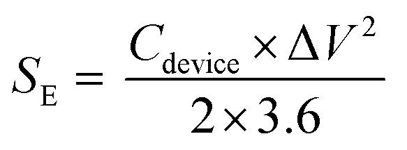
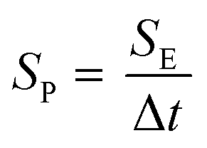
Here Vdrop represents the voltage and ΔI denotes the current associated with the IR drop. The variable I represents the applied current, while Δt represents the duration of charge or discharge. Additionally, specific energy (SE, W h kg−1) and specific power (SP, W kg−1) were calculated using eqn (3) and (4).24 Additionally, the coulombic efficiency also known as charge efficiency, defined as the ratio of the charge extracted from an energy storage device during discharge to the charge stored in the device during the charging process, was also calculated using eqn (5).28| |  | (3) |
| |  | (4) |
| |  | (5) |
3 Results and discussion
3.1. Material characterization
To confirm the grafting of dopamine onto BAC, material characterization of BAC and DPBAC-based electrodes was studied using BET, TGA, Raman spectra, TEM, and XPS analysis. The nitrogen adsorption/desorption isotherms of BAC and DPBAC are depicted in Fig. 2a, and the inset shows the plot of differential pore volume versus pore width. For both BAC and DPBAC, a combination of type I and type II isotherms was observed at low and high relative pressures (p/p0) respectively. This behaviour is characteristic of microporous materials. Additionally, reduction of 16% and 17% in the BET-specific surface area and pore volume, from 2243 to 1901 m2 g−1 and 1.35 to 1.12 cm3 g−1 respectively, was observed when comparing the BAC with the DPBAC which signified the grafting of dopamine on activated carbon micropores. Tisawat and coworkers (2019) observed similar occurrences upon functionalizing AC with anthraquinone and 9,10-phenanthrenequinone, as reported in their study.11 Furthermore, Fig. 2b displays the thermogravimetric (TG) analysis results for BAC, commercial dopamine and DPBAC. Up to 650 °C, commercial dopamine completely loses mass whereas BAC and DPBAC demonstrate mass loss of approximately 3% and 11% respectively. The results suggest that BAC exhibits the presence of minimal oxygenated functionalities on their surfaces; on the other hand, DPBAC releases decomposition products associated with surface functionality modification. The obtained TGA results also confirmed that the modification procedure successfully introduced only the intended dopamine molecules on the surface of BAC. The Raman spectra of BAC and DPBAC were recorded to identify the carbonaceous nature of both samples. Fig. 2c represents the normalized Raman spectra within the wavenumber range from 250 cm−1 to 3500 cm−1. In the case of BAC, the four absorption bands associated with 1340, 1598, 2695, and 2937 cm−1 peaks are attributed to the defect sites (D-band), stretching of the vibrational states of sp2 hybridized carbon (G-band), and the last two high-frequency components correspond to second order scattering processes together with the defect mode-activation.29,30 On the other hand, the DPBAC shows different peak components within the range of 600 to 1300 cm−1 that correspond to typical aliphatic chains.31 A clear difference between the BAC and the DPBAC Raman spectra can be observed and depicted as the different bands (D, G, 2D and D + D′) in BAC have undergone thorough modification that include suppressing, broadening as well as shifting of peaks due to π–π stacking with dopamine molecules. For instance, the broad peaks at 1321 cm−1 and an intense peak at 1605 cm−1 confirm the interaction of aliphatic and aromatic components between the BAC molecule and dopamine molecule.32,33 The dopamine peaks at higher wavelength shifts, specifically 2927 and 3073 cm−1, match the Raman spectrum provided by the chemical supplier (Sigma-Aldrich). An alternate explanation for the existence of these peaks is the presence of decorated protonated amine on one end of the aliphatic chain of the dopamine molecule.34
 |
| | Fig. 2 (a) N2 adsorption isotherms and desorption isotherms measured at 77 K (inset shows the pore size distribution of BAC and DPBAC), (b) TG analysis of BAC, commercial dopamine and DBPAC under a N2 atmosphere and (c) Raman spectra of BAC and DPBAC. | |
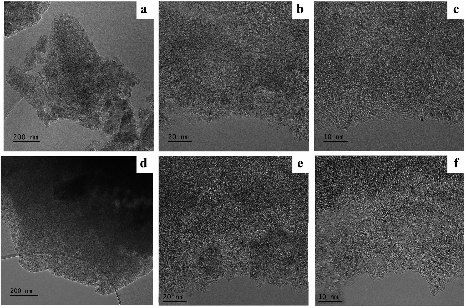
Moreover, the zeta potential of DPBAC reduced from −24.8 mV (BAC) (Fig. S4†) to −13.6 mV (Fig. S5†) because the commercially available dopamine hydrochloride is an amine-containing compound and displays a zeta potential of +5.28 mV (Fig. S6†) which decreased the overall surface zeta potential of BAC upon π–π stacking indicating the successful grafting of dopamine on the BAC surface. Moreover, we employed TEM and FESEM to explore deeper into the morphology of DPBAC. TEM images of BAC (Fig. 3a–c) were compared with those of DPBAC (Fig. 3d–f). Upon careful evaluation, it was found that the dark patches observed in the DPBAC images are likely due to variations in sample thickness rather than dopamine grafting. No significant differences were noted between the samples. Additionally, the FE-SEM image (Fig. S7†) corroborates the TEM findings.
 |
| | Fig. 3 TEM images of BAC (a–c) and DPBAC (d–f) captured at varying magnifications. | |
To gain a deeper insight into the chemical bonding between dopamine and BAC, we employed XPS analysis. The XPS-wide scan results, along with the deconvoluted core level spectra for C 1s and O 1s of the BAC and C 1s, O 1s, and N 1s for DPBAC are presented in Fig. 4. The XPS survey scan distinctly revealed a nitrogen (N) peak in DPBAC, consequently providing confirmation of the grafting of dopamine onto BAC, as illustrated in Fig. 4a. The high-resolution XPS analysis of core levels demonstrated distinct findings. The carbon (C) peak exhibited variations at 284.2 eV, 285.1 eV, and 286.8 eV, corresponding to sp2 C (C![[double bond, length as m-dash]](https://www.rsc.org/images/entities/char_e001.gif) C), C–N, and C–O interactions, respectively, as reported in prior research. A novel CO (carbonyl) peak at 290.07 eV emerged post-dopamine loading, unequivocally indicating the incorporation of dopamine into the DPBAC composite structure as depicted in Fig. 4d.8,11 Regarding oxygen (O) peak detection in the O 1s region, distinctive assignments were observed at 531.2 eV (CO) as displayed in Fig. 4e.8,12 These assignments aligned with the C 1s spectra outcomes, further corroborating the results. Furthermore, the peak located at 401.2 eV (Fig. 4f) is attributed to the presence of a primary amine (R–NH2), providing evidence for the existence of dopamine that is non-covalently attached.12 The energies and the identified chemical groups in the XPS analyses align closely with prior findings8,11,12 and provide further confirmation of the successful grafting of dopamine on the surface of the BAC electrode.
C), C–N, and C–O interactions, respectively, as reported in prior research. A novel CO (carbonyl) peak at 290.07 eV emerged post-dopamine loading, unequivocally indicating the incorporation of dopamine into the DPBAC composite structure as depicted in Fig. 4d.8,11 Regarding oxygen (O) peak detection in the O 1s region, distinctive assignments were observed at 531.2 eV (CO) as displayed in Fig. 4e.8,12 These assignments aligned with the C 1s spectra outcomes, further corroborating the results. Furthermore, the peak located at 401.2 eV (Fig. 4f) is attributed to the presence of a primary amine (R–NH2), providing evidence for the existence of dopamine that is non-covalently attached.12 The energies and the identified chemical groups in the XPS analyses align closely with prior findings8,11,12 and provide further confirmation of the successful grafting of dopamine on the surface of the BAC electrode.
 |
| | Fig. 4 (a) Comparative XPS analysis of DPBAC in relation to BAC, deconvoluted, (b) C 1s and (c) O 1s spectra acquired through high-resolution XPS analysis of BAC, deconvoluted, (d) C 1s, (e) O 1s and (f) N 1s spectra derived from high-resolution XPS measurements of DPBAC. | |
3.2. Electrochemical characterization
The CV and GCD measurements were recorded at a scan rate of 5 mV s−1 and a current density of 0.02 A g−1 to investigate dopamine's impact on BAC's electrochemical properties in the Reline electrolyte. Fig. 5a and b show CV and GCD curves recorded at 5 mV s−1 and 0.02 A g−1, respectively. CV curves exhibit a quasi-rectangular shape, aligned with the zero-baseline current line. This observation holds true for different scan rates within a voltage window of 0 to 2.0 V. Comparing the CV and GCD curves of the BAC and DPBAC devices, it is evident that the grafting of dopamine on BAC considerably improved the specific capacitance of the DPBAC device as compared to the BAC device. The specific capacitances, derived from discharge profiles at 0.2 A g−1, were determined to be 23 F g−1 for BAC and 39 F g−1 for DPBAC, respectively. This enhancement was primarily facilitated by the presence of active dopamine molecules, which engage in a reversible redox reaction involving two electrons and two protons.
 |
| | Fig. 5 (a) CV curves of the BAC and DPBAC devices compared at a scan rate of 5 mV s−1, (b) GCD curves of the BAC and DPBAC devices recorded at a current density of 0.02 A g−1 illustrate plots depicting the (c) reciprocal of specific capacitance (Cs−1) against the square root of the scan rate (ν0.5) and (d) displays plots of specific capacitance (Cs) against the reciprocal of the square root of the scan rate (ν−0.5). The solid and dotted lines represent linear fits applied to the data points of BAC and DPBAC, while the inset features the linear fit equation along with the root mean square. | |
To distinguish between faradaic and non-faradaic components contributing to the overall charge storage, we employed the Trasatti method.35,36 The analysis depends on the theory that the surface and diffusion-controlled contributions are governed by different kinetics and respond differently to increasing scan rates. Initially, we determined the specific capacitance (Cs) by analyzing CV curves obtained at various scan rates (specifically ≤10 mV s−1), utilizing the following equation:
| |  | (6) |
Here
Cs represents the specific capacitance (in F g
−1), Δ
V stands for the potential window (in V),
S denotes the area enclosed by the cyclic voltammograms (in mA V),
m and
ν indicate the mass of the whole device and potential scan rate (in mV s
−1) respectively. We hypothesized that ion diffusion adheres to a semi-infinite diffusion pattern, implying an anticipated linear correlation between the reciprocal of the calculated specific capacitance (
Cs−1) and the square root of scan rates (
ν0.5), as depicted in
Fig. 5c:
| |  | (7) |
CT denotes the total capacitance, which encompasses the maximum capacitance arising from the sum of the electrical double-layer capacitance (
CEDL) and pseudo-capacitance (
CPSEUDO).
We evaluated the maximum CEDLS and maximum CPSEUDO by establishing a linear relationship between the calculated specific capacitances (Cs) and the reciprocal of the square root of scan rate (ν(−0.5)) (refer to Fig. 5d), which is expressed by the following equation:
CEDLC was determined by performing a linear fit and extrapolating the fitting line to the
y-axis, while
CPSEUDO can be determined by subtracting
CEDLC from the
CT. The capacitance contribution of
CEDLC and
CPSEUDO in percentages was calculated using the following equations.
The results clearly indicate that within the DPBAC devices, CPSEUDO and CEDLC account for 69.8% and 30.2% of charge storage contributions respectively. Conversely, within the BAC device, these contributions were distributed as 21.1% and 78.9% respectively when the scan rate was less or equal to between 1 and 5 mV s−1. In DPBAC, CPSEUDO predominantly originates from dopamine, whereas in BAC, various internal factors such as pores, voids, grain boundaries, cracks, dislocations (including both edge and screw dislocations), and crevices may be accountable for its occurrence. The results of Trassati analysis clearly showed how grafting of dopamine significantly influences total charge storage.
| |  | (9) |
| |  | (10) |
Furthermore, the rate performance of BAC and DPBAC-based SCs was evaluated by plotting specific capacitance against current density, as shown in Fig. 6a. When the current density increased from 0.02 A g1 to 0.2 A g−1, the BAC-based SCs retained approximately 60% of its capacitance, while the DPBAC-based SCs retained about 75%, demonstrating superior stability under increasing current density. Electrochemical impedance spectroscopy (EIS) measurement was performed for the BAC and DPBAC based SCs and the recorded Nyquist plots are displayed in Fig. 6b. EIS was recorded at open circuit potential (OCP) over a frequency range of 1000 kHz to 0.01 Hz with an amplitude of 5 mV. The ESR was determined by examining the real part of the complex impedance at 1 kHz on a Nyquist plot.37
 |
| | Fig. 6 (a) Rate performance, (b) the Nyquist plots (insets show magnification of the high-frequency region), (c) capacitance retention rate and coulombic efficiency for BAC and DPBAC-based SCs. | |
The ESR values were found to be 8.2 Ω and 9.5 Ω for the DPBAC and BAC-based SCs, respectively. It is worth emphasizing that the ESR obtained from EIS is usually smaller than the ESR from the GCD curve. Additionally, the cycling stability of DPBAC and BAC-based SCs was rigorously assessed through repeated charging and discharging at a current density of 0.2 A g−1. As shown in Fig. 6c, the DPBAC device retained 87% of its capacitance after 10000 cycles, while the BAC-based supercapacitor retained 94%, highlighting its excellent cycling performance. These retention rates for DPBAC based SCs demonstrate comparability, and even superiority, when compared to retention rates reported for other quinone-carbon based devices such as polydopamine supported on functionalized carbon cloth-based devices (PDA-FCC//PVA-H2SO4//PDA-FCC, 81% after 10000 cycles),38 Juglone modified activated carbon//1 M H2SO4//activated carbon (77% after 3000 cycles),39 Juglone modified CNT-bacterial cellulose//PVA-H2SO4//activated carbon (82.4% after 10000 cycles),40 Emodin-graphene nanosheet//1 M H2SO4//caffeic acid-graphene hydrogel (80% after 7000 cycles),41 anthraquinone-2,6-disulfonic acid disodium salt graphene/polypyrrole (AQDS-GPy//1 M H2SO4//AQDS-GPy, 86% after 2000 cycles),42 and dihydroxy-p-benzoquinone/reduced graphene oxide (DHBQ/rGO-0.5)//1 M H2SO4 benz[a]anthracene-7,12-quinone (BAQ/rGO-0.3) (86% after 5000 cycles).43 The Coulomb efficiency of the BAC and DPBAC-based SCs was recorded every 2000 cycles, as shown in Fig. 6c. Both SCs maintained approximately 98% efficiency after 10000 cycles at 0.2 A g−1, indicating good electrochemical stability.
3.3. Charge storage mechanism
The application of dopamine grafting onto BAC substantially enhances the electrochemical properties exhibited by the DPBAC device. The operational principles of two electroactive substances, namely BAC and dopamine, exhibit notable distinctions (refer to Fig. 7 for a depiction of the charge storage mechanism). Carbon predominantly relies on the electrostatic mechanism, whereas dopamine predominantly involves a pseudocapacitive mechanism. At the outset of the charging phase, at the positive electrode, redox-active entities like dopamine experience oxidation, leading to an augmentation in the concentration of oxidized constituents such as dopamine quinones. Concurrently, protons and sodium cations migrate towards the aqueous electrolyte, while anions become integrated into the electrode material. Conversely, at the negative electrode, dopamine quinone entities undergo reduction, liberating chloride anions into the aqueous electrolyte, with cations assimilating into the electrode material. These processes undergo reversal during the discharging phase, as visually demonstrated in Fig. 7. A simultaneous charge storage mechanism encompasses the maintenance of electrode charge equilibrium through the presence of electrolyte ions at the interface between BAC and the electrolyte. This amalgamation of pseudocapacitive and electrostatic mechanisms assumes a paramount role in governing the charge storage process within DPBAC devices. Additionally, this improvement arises from several key factors: (i) dopamine grafting introduces functional groups onto the surface of activated carbon, thereby altering its chemical composition and providing novel active sites that facilitate electrochemical reactions, (ii) dopamine's capacity to undergo redox reactions contribute to pseudocapacitance, boosting the energy storage capacity of the activated carbon material, (iii) the interaction between dopamine and activated carbon initiates synergistic effects that harmonize the strengths of both components, optimizing the overall electrochemical performance. Collectively, the grafting of dopamine onto activated carbon produces a composite material endowed with enriched electrochemical properties.
 |
| | Fig. 7 Charge storage mechanism in the DPBAC electrode. | |
3.4. Electrochemical performance of the 3D printed fully biocompatible SC (3DPBSC)
To achieve the development of a fully biocompatible SC (3DPBSC), we employed 3D printing techniques to print the electrodes using DPBAC electrode materials and electrolytes based on Reline. This approach ensures the utilization of environmentally friendly materials throughout the SC structure including graphite ink as the current collector, cellulose as the separator, and PLA substrate, promoting sustainability and biodegradability. Fig. 8a shows the Reline ink viscosity as a function of shear rate. To facilitate effective application through methods like Piezo jet printing, ink compositions should possess viscosities within the range of about 50 to 200000 cps. The viscosity of Reline (500 cp at 1 s−1) meets the requirements for piezo jet printing therefore parameters such as stroke, open cycles, close volts, and pressure were precisely optimized to ensure the efficient printing of Reline onto electrode materials. The printing process was repeated two times to ensure a sufficient loading of Reline, effectively saturating both the pores and surface of the electrode. Moreover, the properties of Reline, choline chloride and urea were investigated using infrared spectroscopy. As shown in Fig. 8b, the FTIR spectra of urea exhibited peaks at 3426 cm−1 and 3328 cm−1 corresponding to anti-symmetric and symmetric N–H stretching vibrations, respectively.44 The peak at 1675 cm−1 was attributed to CO stretching, while the peak at 1585 cm−1 was assigned to N–H deformation. Additionally, the signal at 1455 cm−1 corresponded to C–N group stretching. For choline chloride, a characteristic peak was observed at 3215 cm−1, corresponding to O–H stretching. Vibrational bands at 3000 cm−1 and 1480 cm−1 were associated with CH2 bending of an alkyl group, and the signal at 1665 cm−1 corresponded to H–O bending. The region from 1080 cm−1 to 628 cm−1 was identified as the fingerprint region for the alkyl group. In the Reline mixture, broad peaks were observed in the range of 3320–3192 cm−1, attributed to the stretching bands of OH and N–H groups. This broad band was deformed by hydrogen bonding interactions between urea and choline chloride. Moreover, the N–H and CO stretching vibrations of urea in Reline exhibited a slight blue shift, from 1455 cm−1 to 1606 cm−1 and from 1585 cm−1 to 1665 cm−1, respectively. This shift indicated the formation of hydrogen bonds between the amino group in urea and the Cl in choline chloride.45
 |
| | Fig. 8 (a) Viscosity of Reline as a function of shear rate at room temperature, (b) FTIR spectra of Reline, (c) a digital image of the electrolyte holder, (d) the liquid holder connected to the electrochemical workstation, and (e) the Nyquist plot of Reline with the inset showing a magnified view at high frequency. | |
The ionic conductivity of the Reline electrolyte was determined using the following eqn:15
| |  | (11) |
where
σ denotes the ionic conductivity (mS cm
−1),
L signifies the electrolyte thickness (distance between the electrodes), and
A is the tested area of the electrolyte in the direction of ion flow. For our liquid sample holder,
L is 0.1 cm and
A is 10.5 cm
2.
R represents the bulk resistance, expressed as the ohmic resistance, measured using EIS.
Fig. 8c and d show the images of the liquid sample holder and its connection to the electrochemical workstation, while
Fig. 8e presents the recorded Nyquist plot for the Reline electrolyte. The ionic conductivity was found to be 1.4 mS cm
−1 for the Reline electrolyte which matched with the reported value (1.35 mS cm
−1) in the literature.
16 A comparison of the electrochemical performances of the aqueous electrolyte and Reline is displayed in Fig. S8.
† The CV and GCD curves of 3DPBSC at various scan rates and currents are presented in
Fig. 9a and b, respectively. Notably, the CV curves exhibit a consistent quasi rectangular shape across different scan rates, while the GCD curve maintains a uniform quasi triangular profile. These observations indicate robust electrochemical performance within the specified voltage window of 0–2.0 V.
 |
| | Fig. 9 (a) CV, (b) GCD curves, (c) Ragone plots of 3DPBSC compared with the values of similar quinone-carbon based devices from ref. 38, 39, 47, 48 and 50 and (d) practical demonstration of 3DPBSC illuminating an LED. | |
3DPBSC demonstrates the highest specific capacitance of 39 F g−1 at a current density of 0.2 A g−1 (96 F g−1 at 1 mV s−1) with 15 Ω ESR which is comparable with the SC assembled using the polydopamine supported on functionalized carbon cloth electrode and H2SO4/PVA hydrogel-based aqueous electrolyte in the voltage range of 1.2 V.38 It is consistently advisable to undertake meaningful comparisons of the electrochemical performances of energy materials, whether similar or dissimilar. This necessitates the consistent utilization of fabrication and testing parameters. These parameters encompass essential factors, such as coating thickness, discharge current, application of electrolyte, current collector, etc.28,37,46 To the best of our knowledge, no researcher has previously employed an identical combination of elements, including the current collector, electrode, electrolyte, or fabrication method. Therefore, a meaningful comparison of its electrochemical performance with the existing literature, specifically in terms of specific capacitance, ESR, and LC, is not warranted. However, in contrast to Aeby et al. 2021, who reported a specific capacitance of 25.6 F g−1 at 1 mV s−1 for 1.2 V using a fully EDLC-based 3D printed disposable SC,2 our current study demonstrates a notably higher specific capacitance of 96 F g−1 at 1 mV s−1 (for 2.0 V), specifically in comparison with fully biocompatible SCs.
Specific energy and specific power density are key metrics to evaluate the performance of SCs. 3DPBSC delivered a high specific energy of 28 W h kg−1 at a specific power of 102 W kg−1 and was able to maintain a specific energy of 22 W h kg−1 at a high specific power of 1835 W kg−1. It is noteworthy that the specific energy achieved in this study surpasses that of various quinone modified carbon based SCs reported in the literature, for instance, compared to a polydopamine-functionalized carbon cloth SC (symmetric, PVA-H2SO4 (0–1.2 V), which exhibited a specific energy of 11.7 W h kg−1 at a specific power of 385.3 W kg−1),38 an anthraquinone-functionalized highly porous graphitic carbon fiber SC (asymmetric, 1 M H2SO4 (0–1.2 V), with a specific energy of 19.3 W h kg−1 at a specific power of 300 W kg−1),47 a p-phenylenediamine-covalently grafted dissected carbon nanotube SC (symmetric, 1 M H2SO4 (0–1.6 V), which demonstrated a specific energy of 19.1 W h kg−1 at a specific power of 800 W kg−1),48 and a quinone-coated carbon onion SC (1 M H2SO4 (0–0.8 V), symmetric, achieving 4.5 W h kg−1).49 Additionally, in comparison to alizarin-grafted graphene hydrogels (symmetric, 1 M H2SO4 (0–1.4 V), with a specific energy of 18.2 W h kg−1 at a specific power of 700 W kg−1),50 Juglone modified activated carbon (asymmetric, 1 M H2SO4 (0–1.2 V), specific energy of 12 W h kg−1 at a specific power of 180 W kg−1),39 our work demonstrates improved performance presented in Fig. 9c. In the end, the practical performance evaluation of the fabricated 3DPBSC was conducted by illuminating a commercially available 1.8 V red light-emitting diode (LED). The 3DPBSC was charged from 0 to 2 V at 0.06 A g−1 for 15 min, followed by discharging through the LED. As depicted in Fig. 9d, the LEDs emitted strong light for 20 minutes, demonstrating the remarkable energy storage and discharge capabilities of the 3DPBSC. The present study showcases the potential of 3D printed, flexible, sustainable, fully biocompatible devices. These could encompass consumer electronics, transient medical implants, environmental sensors, and even wearable technologies. The versatility of the biocompatible materials offers a novel approach to reducing electronic waste and minimizing the environmental impact of modern devices.
4. Conclusions
In summary, a fully biocompatible SC was successfully fabricated using PLA, graphite, dopamine-grafted activated carbon, Reline, cellulose with corresponding components such as the substrate, current collector, electrode, electrolyte, and separator, respectively. 3DPBSC exhibited the highest capacitance of 96 F g−1 at a scan rate of 1 mV s−1 and delivers a high specific energy of 22 W h kg−1 at a specific power of 1835 kW kg−1, along with good cycling stability of 87% over 10000 charge–discharge cycles. The presented work represents a promising approach for the development of 3D printed, flexible, sustainable, non-toxic, and fully biocompatible SC for low-power wireless sensor applications.
Data availability
The datasets generated and/or analyzed during this study will be available in the Trepo, the institutional repository of Tampere University (https://trepo.tuni.fi/). Additionally, ESI† files accompanying this manuscript include raw data of few measurements. For any further data requests, please contact the corresponding author at E-mail: chirag.mevada@tuni.fi.
Author contributions
Chirag Mevada was involved in designing experiments, synthesizing electrodes, electrolyte, material and electrochemical characterization, optimizing the printing parameters for the current collector, electrodes and electrolyte, fabricating devices, and drafting the manuscript. Jonne Tissari contributed by assisting in printing the current collector and electrode. Vijay Singh Parihar's contributions included helping in synthesizing electrodes, and electrolytes, as well as conducting TGA analysis. Amit Tewari provided support with Raman analysis, writing its sections, and performing XPS analysis. Jari Keskinen guided the device fabrication process and contributed to manuscript revisions. Minna Kellomäki assisted with revising the manuscripts. Matti Mäntysalo significantly contributed to experimental design, feasibility analysis, and manuscript revisions.
Conflicts of interest
The authors declare no potential conflicts of interest regarding this article's research, authorship, and publication.
Acknowledgements
This study was made possible through the support of the Academy of Finland, under grant number 350309, for the CHIST-ERA TESLA Transient Electronics for Sustainable ICT in Digital Agriculture project. Additionally, we utilized the Academy of Finland Research Infrastructure, “Printed Intelligence Infrastructure” (PII-FIRI), funded under Grant Number 320019. The electron microscopy work was conducted at the Tampere Microscopy Center, Tampere University. We acknowledge Senior Scientist Mari Honkanen of Tampere University for her assistance with FESEM and TEM characterization, and Laboratory Coordinator Leo Hyvärinen, Tampere University for his help with BET analysis. We also extend our gratitude to VTT for providing the biodegradable PLA substrate used in fabricating the supercapacitor.
References
- A. Borenstein, O. Hanna, R. Attias, S. Luski, T. Brousse and D. Aurbach, J. Mater. Chem. A, 2017, 5, 12653–12672 RSC.
- X. Aeby, A. Poulin, G. Siqueira, M. K. Hausmann and G. Nyström, Adv. Mater., 2021, 2101328, 1–9 Search PubMed.
- F. Zhang, M. Wei, V. V. Viswanathan, B. Swart, Y. Shao, G. Wu and C. Zhou, Nano Energy, 2017, 40, 418–431 CrossRef CAS.
- M. Idrees, S. Ahmed, Z. Mohammed, N. S. Korivi and V. Rangari, Addit. Manuf., 2020, 36, 101525 CAS.
- M. Li, S. Zhou, L. Cheng, F. Mo, L. Chen, S. Yu and J. Wei, Adv. Funct. Mater., 2023, 33(1–29), 2208034 CrossRef CAS.
- C. Schütter, S. Pohlmann and A. Balducci, Adv. Energy Mater., 2019, 9, 1–11 Search PubMed.
- S. P. Ega and P. Srinivasan, J. Energy Storage, 2022, 47, 103700 CrossRef.
- J. Liu, Y. Yuan, H. Fang, Y. Xu, W. Sun, S. Chen, Y. Wang and L. P. Lv, ACS Appl. Energy Mater., 2022, 5, 8112–8122 CrossRef CAS.
- G. Pognon, T. Brousse, L. Demarconnay and D. Bélanger, J. Power Sources, 2011, 196, 4117–4122 CrossRef CAS.
- A. Gouda, A. Masson, M. Hoseinizadeh, F. Soavi and C. Santato, Commun. Chem., 2022, 5, 1–10 CrossRef PubMed.
- N. Tisawat, C. Samart, P. Jaiyong, R. A. Bryce, K. Nueangnoraj, N. Chanlek and S. Kongparakul, Appl. Surf. Sci., 2019, 491, 784–791 CrossRef CAS.
- T. Purkait, N. K. Dimple, M. Das, S. Sarkar, A. De Sarkar and R. S. Dey, J. Mater. Chem. A, 2020, 8, 6740–6756 RSC.
- R. Wang, M. Yao, S. Huang, J. Tian and Z. Niu, Adv. Funct. Mater., 2021, 31(1–9), 2009209 CrossRef CAS.
- Y. J. Jo, H. Kim, J. Ok, Y. J. Shin, J. H. Shin, T. H. Kim, Y. Jung and T. il Kim, Adv. Funct. Mater., 2020, 30(1–12), 1909707 CrossRef CAS.
- M. B. Durukan, D. Keskin, Y. Tufan, O. Dincer, M. O. Cicek, B. Yildiz, S. Çınar Aygün, B. Ercan and H. E. Unalan, Adv. Funct. Mater., 2024, 34(1–12), 2307051 CrossRef CAS.
- S. Azmi, M. F. Koudahi and E. Frackowiak, Energy Environ. Sci., 2022, 15, 1156–1171 RSC.
- C. Rokaya, J. Keskinen and D. Lupo, J. Energy Storage, 2022, 50, 104221 CrossRef.
- M. Arvani, J. Keskinen, D. Lupo and M. Honkanen, J. Energy Storage, 2020, 29, 101384 CrossRef.
- Z. Fu, M. Hannula, A. Jauho, V. Kaisa-leena, V. Marja, J. Keskinen and M. Matti, ACS Appl. Mater. Interfaces, 2022, 14, 40145–44015 CrossRef CAS PubMed.
-
Z. Fu, A. Jauho, K. L. Vaisanen, M. Valimaki, J. Keskinen and M. Mantysalo, in FLEPS 2022 – IEEE International Conference on Flexible and Printable Sensors and Systems, Proceedings, Institute of Electrical and Electronics Engineers Inc., 2022 Search PubMed.
- H. Pourkheirollah, J. Keskinen, M. Mäntysalo and D. Lupo, J. Power Sources, 2023, 567, 232932 CrossRef CAS.
- H. Pourkheirollah, J. Keskinen, M. Mäntysalo and D. Lupo, J. Power Sources, 2022, 535, 231475 CrossRef CAS.
- C. Mevada and M. Mukhopadhyay, J. Energy Storage, 2020, 30, 101453 CrossRef.
- C. Mevada and M. Mukhopadhyay, J. Energy Storage, 2020, 31, 101587 CrossRef.
- C. Mevada, P. S. Chandran and M. Mukhopadhyay, J. Energy Storage, 2020, 28, 101197 CrossRef.
- E. Luoma, M. Välimäki, T. Rokkonen, H. Sääskilahti, J. Ollila, J. Rekilä and K. Immonen, J. Plast. Film Sheeting, 2021, 37, 429–462 CrossRef CAS.
- E. Inci Yesilyurt, J. Pionteck, F. Simon and B. Voit, RSC Applied Polymers, 2023, 1, 97–110 RSC.
- A. Noori, M. F. El-Kady, M. S. Rahmanifar, R. B. Kaner and M. F. Mousavi, Chem. Soc. Rev., 2019, 48, 1272–1341 RSC.
- N. Kostoglou, C. Koczwara, S. Stock, C. Tampaxis, G. Charalambopoulou, T. Steriotis, O. Paris, C. Rebholz and C. Mitterer, Chem. Eng. J., 2022, 427, 131730 CrossRef CAS.
- A. Tewari, S. Gandla, S. Bohm, C. R. McNeill and D. Gupta, FlatChem, 2019, 16, 100110 CrossRef CAS.
- D. Mallinson, A. B. Mullen and D. A. Lamprou, J. Mater. Sci., 2018, 53, 3198–3209 CrossRef CAS PubMed.
- S. H. Ku and C. B. Park, Biomaterials, 2010, 31, 9431–9437 CrossRef CAS PubMed.
- J. X. Ma, H. Yang, S. Li, R. Ren, J. Li, X. Zhang and J. Ma, RSC Adv., 2015, 5, 97520–97527 RSC.
- R. W. Berg, T. Nrbygaard, P. C. White and S. Abdali, Appl. Spectrosc. Rev., 2011, 46, 107–131 CrossRef CAS.
- M. R. Thalji, G. A. M. Ali, H. Algarni and K. F. Chong, J. Power Sources, 2019, 438, 227028 CrossRef CAS.
- C. Mevada and M. Mukhopadhyay, Mater. Chem. Phys., 2020, 245, 122784 CrossRef CAS.
- S. Zhang and N. Pan, Adv. Energy Mater., 2015, 5, 1–19 Search PubMed.
- M. Moloudi, M. S. Rahmanifar, A. Noori, X. Chang, R. B. Kaner and M. F. Mousavi, J. Mater. Chem. A, 2021, 9, 7712–7725 RSC.
- X. He, Q. Chen, X. Mao, W. Liu, Y. Zhou, W. Yang, Y. Yang and J. Xu, RSC Adv., 2019, 9, 30809–30814 RSC.
- D. Fang, J. Zhou, L. Sheng, W. Tang and J. Tang, Chem. Eng. J., 2020, 396, 125325 CrossRef CAS.
- L. Hou, C. Kong, Z. Hu, Y. Han and B. Wu, J. Electroanal. Chem., 2021, 895, 115402 CrossRef CAS.
- Y. Han, T. Wang, T. Li, X. Gao, W. Li, Z. Zhang, Y. Wang and X. Zhang, Carbon, 2017, 119, 111–118 CrossRef CAS.
- L. Hou, C. Kong, Z. Hu, Y. Yang, H. Wu, Z. Li, X. Wang, P. Yan and X. Feng, Appl. Surf. Sci., 2020, 508, 145192 CrossRef CAS.
- D. Yue, Y. Jia, Y. Yao, J. Sun and Y. Jing, Electrochim. Acta, 2012, 65, 30–36 CrossRef CAS.
- X. Song, W. Hu, W. Huang, H. Wang, S. Yan, S. Yu and F. Liu, Chem. Eng. J., 2020, 388, 124324 CrossRef.
- C. Mevada and M. Mukhopadhyay, Ind. Eng. Chem. Res., 2021, 60, 1096–1111 CrossRef CAS.
- H. Wang, H. Yi, C. Zhu, X. Wang and H. Jin Fan, Nano Energy, 2015, 13, 658–669 CrossRef CAS.
- Y. He, X. Yang, N. An, X. Wang, Y. Yang and Z. Hu, New J. Chem., 2019, 43, 1688–1698 RSC.
- D. M. Anjos, J. K. McDonough, E. Perre, G. M. Brown, S. H. Overbury, Y. Gogotsi and V. Presser, Nano Energy, 2013, 2, 702–712 CrossRef CAS.
- N. An, Y. An, Z. Hu, B. Guo, Y. Yang and Z. Lei, J. Mater. Chem. A, 2015, 3, 22239–22246 RSC.
|
| This journal is © The Royal Society of Chemistry 2024 |
Click here to see how this site uses Cookies. View our privacy policy here. 
 Open Access Article
 This Open Access Article is licensed under a
  *a,
Jonne
Tissari
*a,
Jonne
Tissari