
 Open Access Article
 This Open Access Article is licensed under a
 Creative Commons Attribution 3.0 Unported Licence
Modulating proton conductivity through crystal structure tuning in arenedisulfonate coordination polymers†
Chao
Sun
ab,
Christopher M.
Pask
 b,
Sang T.
Pham
abc,
Emilio
Rapaccioli
b,
Andrew J.
Britton
ac,
Stuart
Micklethwaite
ac,
Andrew
Bell
a,
Maximilian O.
Besenhard
d,
Rik
Drummond-Brydson
ac,
Ke-Jun
Wu
ae and
Sean M.
Collins
*abc
b,
Sang T.
Pham
abc,
Emilio
Rapaccioli
b,
Andrew J.
Britton
ac,
Stuart
Micklethwaite
ac,
Andrew
Bell
a,
Maximilian O.
Besenhard
d,
Rik
Drummond-Brydson
ac,
Ke-Jun
Wu
ae and
Sean M.
Collins
*abc
aSchool of Chemical and Process Engineering, University of Leeds, Leeds LS2 9JT, UK. E-mail: S.M.Collins@leeds.ac.uk
bSchool of Chemistry, University of Leeds, Leeds LS2 9JT, UK
cBragg Centre for Materials Research, University of Leeds, Leeds LS2 9JT, UK
dDepartment of Chemical Engineering, University College London, London WC1E 7JE, UK
eZhejiang Provincial Key Laboratory of Advanced Chemical Engineering Manufacture Technology, College of Chemical and Biological Engineering, Zhejiang University, Hangzhou, 310027, China
First published on 19th June 2024
Abstract
The functional group-directed structures of coordination polymers (CPs) and metal–organic frameworks (MOFs) have made them key candidates for proton exchange membranes in fuel cell technologies. Sulfonate group chemistry is well established in proton conducting polymers but has seen less exploration in CPs. Here, we report solvent-directed crystal structures of Cu2+ and Ca2+ CPs constructed with naphthalenedisulfonate (NDS) and anthraquinone-1,5-disulfonate (ADS) ligands, and we correlate single crystal structures across this set with proton conductivities determined by electrochemical impedance spectroscopy. Starting from the Cu2+-based NDS and aminotriazolate MOF designated Cu-SAT and the aqueous synthesis of the known Ca2+-NDS structure incorporating water ligands, we now report a further five sulfonate CP structures. These syntheses include a direct synthesis of the primary degradation product of Cu-SAT in water, solvent-substituted Ca-NDS structures prepared using dimethylformamide and dimethylsulfoxide solvents, and ADS variants of Cu-SAT and Ca-NDS. We demonstrate a consistent 2D layer motif in the NDS CPs, while structural modifications introduced by the ADS ligand result in a 2D hydrogen bonding network with Cu2+ and aminotriazolate ligands and a 1D CP with Ca2+ in water. Proton conductivities across the set span 10−4 to >10−3 S cm−1 at 80 °C and 95% RH. These findings reveal an experimental structure–function relationship between proton conductivity and the tortuosity of the hydrogen bonding network and establish a general, cross-structure descriptor for tuning the sulfonate CP unit cell to systematically modulate proton conductivity.
1. Introduction
Metal–organic coordination polymers (CPs), encompassing one-dimensional (1D) chains, two-dimensional (2D) sheets, and three-dimensional (3D) frameworks built from the interconnection of metal ions or clusters and organic linkers,1 have been widely used in the fields of catalysis,2,3 gas adsorption/separation4,5 and energy storage.6,7 Many CPs have been developed using carboxylate and N-donor ligands, including the now-widespread microporous CPs or metal–organic frameworks (MOFs) built from ditopic or tritopic carboxylates for UiO,8 HKUST,9 MIL,10 and IRMOF11 families, imidazolate for the family of zeolitic imidazolate frameworks,12,13 and pyridine- and pyrazine-based MOFs and CPs.14 Phosphonates have also seen application in gas capture15,16 as well as for proton conduction.17 Void structures in 2D or 3D frameworks, characteristic of MOFs, are not necessarily required for the targeted functional properties in proton and ionic conductivity where 1D and dense CPs have likewise shown considerable promise.18 CPs built from sulfonate–metal coordination motifs have, however, seen significantly less exploration.19A number of sulfonate CPs have shown promising proton conductivity,20 attributed to the beneficial proton hopping sites incorporated in the form of sulfonic acid groups.21 The sulfonate group has three O atoms, and the sulfonate unit can assemble metal ions into diverse structural frameworks, with 1D, 2D, and 3D arrangements reported.22 The sulfonate group can coordinate with one O atom participating in coordination of the metal centre (designated η1) or with two O atoms (designated η2) or, alternatively, the sulfonate group can form bridging motifs (η2, μ2).18 In all cases, at least one other O atom provides further hydrogen-bond receptors to anchor proton carriers or to transfer protons.23 As characteristically weakly coordinating groups, sulfonates tend to form CPs with soft metal ions (e.g. Cu2+, Ca2+, Ba2+).24
Sulfonate CPs often appear as 1D or 2D layered structures,25 with far fewer 3D structures reported.26 Combining sulfonate linkers together with N-donor ligands as a structure-directing second ligand has provided a major guiding principle for sulfonate CP design. Kitagawa et al. reported porous 1D-ladder and 2D-sheet frameworks by using 5-sulfoisophthalate ligands with strongly coordinating N-donor ligands (e.g. 4,4′-bispyridylethylene and pyrazine).27 The 1,5-naphthalenedisulfonic acid (NDS) ligand has drawn particular attention25,28 as a ditopic linker that in this sense resembles the common benzenedicarboxylate (BDC) linker in MOFs.11
Recently, a 2D sulfonate CP denoted Cu-SAT has been synthesized combining NDS and 1,2,4-triazol-4-amine (T4A) linkers and shows promising proton conductivity of the order of 10−3 S cm−1 at >95% relative humidity (RH) and 80 °C,20,28 approaching the benchmark conductivities for Nafion proton conducting polymers (∼10−2 to 10−1 S cm−1). In Cu-SAT, μ2 OH groups and triazolate ligands connect Cu2+ ions in a chain with bridging η2, μ2 NDS linkers spanning the 1D Cu2+ chains to form a 2D structure. However, Cu-SAT, like many other MOFs, presents important limitations from a green chemistry perspective29,30 due to the use of dimethylformamide (DMF) in synthesis. Moreover, from a practical standpoint, Cu-SAT also exhibits limited stability on exposure to water, a critical challenge for proton conductivity under humid conditions. As such, we now turn to the role of the solvent in Cu-SAT synthesis and also examine a structurally analogous 2D CP built from only NDS and Ca2+ in aqueous solution.26 The incorporation of coordinating solvent at Ca2+ sites likewise prompts exploration of the role of solvent choice in Ca2+ as well as Cu2+ NDS CPs, and motivates the examination of the as yet unreported proton conductivity of Ca-NDS CPs.
Fig. 1 highlights the unified structural motifs across the Cu-SAT and Ca-NDS CPs. In Cu-SAT (Fig. 1a), the neutral T4A ligands are shown in the axial positions and the anionic OH and NDS ligands are shown in the equatorial positions. The coordination environment in the Ca-NDS system is analogous with the bridging OH along the metal–metal 1D chain adopted by a further set of NDS ligands (Fig. 1b, equatorial positions) and the structural position of the neutral T4A ligand adopted by solvent molecules (L) in the axial positions (L = H2O in the reported Ca-NDS structure26). Fig. 1c presents the molecular structure of the entire NDS and T4A ligands, and Fig. 1d depicts how these components form a characteristic 2D layer structure in Cu-SAT and Ca-NDS CPs.
 | ||
| Fig. 1 Coordination geometry of (a) Cu2+ in Cu-SAT and (b) Ca2+ in Ca-NDS CPs (L denotes coordinating solvent). (c) Molecular structure of the complete NDS and T4A ligands. (d) Schematic diagram of the characteristic 2D structure formed from NDS spanning between 1D metal chains. The blue spheres represent the metal ions separated by representations of the NDS ligand (purple). | ||
The solvent in MOF and CP synthesis is known to play diverse roles including deprotonation of precursors as well as templating void spaces.31,32 The polarity of the solvent can also play a role in directing the final structure and associated topology and porosity.33 The notable role of the solvent as a second ligand in Ca-NDS further invites exploration not only of the solvent choice but also the choice of the arenedisulfonate ligand. Principles of isoreticular chemistry are widespread in MOF synthesis,34,35 and as such we now evaluate extended arenedisulfonate ligands as a further structural tuning parameter. The anthraquinone-2,6-disulfonate (2,6-AQDS) ligand has been reported to form stable alkaline-earth sulfonate CPs with 3D structures, and the metal-to-metal distance of these samples are longer than 2,6-NDS synthesized CPs which also have 3D structures.26,36,37
Here, to mimic the 1,5-NDS ligand we introduce the anthraquinone-1,5-disulfonate ligand (ADS) as a further structure-modifying element. By synthesising a systematic series of Cu2+ and Ca2+ NDS CPs, we now report solvent-directed single crystal structures of Cu-SAT (ethanol, EtOH), Ca-NDS (DMF), and Ca-NDS (dimethylsulfoxide, DMSO). By incorporating the 1,5-ADS ligand, we further introduce a hydrogen bonded network termed Cu-SQAT incorporating sulfonate, quinone, and aminotriazolate moieties as well as a 1D CP built from Ca and 1,5-ADS ligands, denoted Ca-ADS. We then test their proton conductivities to examine the experimental structure–function relationship with a particular focus on changes in the relative positions of the electronegative functional groups along the major hydrogen bond acceptor chains common to the series. Taken together, these structures establish a correlation between proton conductivities and the tortuosity of the CP hydrogen bond acceptor site network. These findings in turn identify a general, cross-structure descriptor for tuning the sulfonate CP crystal structures to systematically modulate proton conductivity.
2. Experimental
2.1 Materials
1,5-Naphthalenedisulfonic acid tetrahydrate (H2NDS, molecular weight: 360.36 g mol−1), T4A (molecular weight: 84.08 g mol−1), copper nitrate hemi(pentahydrate) (molecular weight: 232.59 g mol−1), N,N-dimethylformamide (DMF, ≥99.9%), polyvinylpyrrolidone (PVP) [Mw 360![[thin space (1/6-em)]](https://www.rsc.org/images/entities/char_2009.gif) 000], and polyvinylidene fluoride (PVDF) [Mw 534000] were purchased from Sigma-Aldrich (Merck Group). Calcium nitrate hemi(pentahydrate) (molecular weight: 236.15 g mol−1) was purchased from Thermo Scientific, anthraquinone-1,5-disulfonic acid disodium salt (ADS, molecular weight: 422.31 g mol−1) was purchased from Santa Cruz Biotechnology, dimethyl sulfoxide (DMSO, ≥99.5%) was purchased from Honeywell, and ethanol (EtOH, ≥99.5%) was purchased from VWR International. All chemicals were used as received. Deionized (DI) water (≥18.2 Mohm cm−1) was used for all reactions.
000], and polyvinylidene fluoride (PVDF) [Mw 534000] were purchased from Sigma-Aldrich (Merck Group). Calcium nitrate hemi(pentahydrate) (molecular weight: 236.15 g mol−1) was purchased from Thermo Scientific, anthraquinone-1,5-disulfonic acid disodium salt (ADS, molecular weight: 422.31 g mol−1) was purchased from Santa Cruz Biotechnology, dimethyl sulfoxide (DMSO, ≥99.5%) was purchased from Honeywell, and ethanol (EtOH, ≥99.5%) was purchased from VWR International. All chemicals were used as received. Deionized (DI) water (≥18.2 Mohm cm−1) was used for all reactions.
2.2 Batch synthesis of the different CPs and membrane fabrication
:DMF and water:DMSO solvent ratios were set as 3:10. Calcium nitrate (47.2 mg, 0.2 mmol) was dissolved in DI water (0.3 mL), and DMF (1 mL) was then added as solution 1. H2NDS (72 mg, 0.2 mmol) was dissolved in DI water (0.3 mL), and DMF (1 mL) was then added as solution 2. Next, solutions 1 and 2 were mixed in a 20 mL glass vial and heated in a dry bath heater at 80 °C for 4 h. Ca-NDS (DMSO) was synthesized by substituting DMSO for DMF in the above reaction (1 mL DMSO in each solution). The reaction yield was determined gravimetrically and was recorded as 42.3% ± 2% for Ca-NDS (DMF) and 40% ± 2% for Ca-NDS (DMSO).
2.3 Materials characterization
Powder X-ray diffraction patterns were recorded using a Bruker D2 diffractometer (Cu Kαλ = 1.54184 Å, 2θ scan range = 5°–50°). Single crystal X-ray diffraction measurements were carried out at 100 K on a Rigaku SuperNova diffractometer equipped with an Atlas CCD detector and connected to an Oxford Cryostream low temperature device using Cu Kα radiation (λ = 1.54184 Å) for Cu-SAT (EtOH), Ca-NDS (DMSO), Cu-SQAT, and Ca-ADS and Mo Kα radiation (λ = 0.7103 Å, for larger crystals) for Ca-NDS (DMF). A microfocus X-ray source was used in all cases. The structure was solved by intrinsic phasing using SHELXT38 and refined by a full matrix least squares technique based on the squared structure factor F2 using SHELXL2014.39Table 1 summarizes the crystallographic data for these five CPs. Vesta software (version 3.5.7) was employed to produce calculated XRD patterns from the single crystal structure.| Crystal data | Cu-SAT (EtOH) | Ca-NDS (DMF) | Ca-NDS (DMSO) | Cu-SQAT | Ca-ADSa |
|---|---|---|---|---|---|
| a Ca-ADS was solved from a twinned crystal with two components relatively rotated by approximately 180° about the normal to (100). | |||||
| CCDC number | 2336805 | 2336806 | 2336802 | 2336803 | 2336804 |
| Formula | C14H16Cu2N8O8S2 | C16H20CaN2O8S2 | C14H18CaO8S4 | C18H16Cu2O10S2 | C14H12CaO11S2 |
| Formula weight | 615.55 | 472.54 | 482.60 | 695.59 | 460.44 |
| Temperature/K | 99.99(10) | 100.01(10) | 100.15(10) | 100.00(10) | 100.01(10) |
| Crystal system | Monoclinic | Triclinic | Monoclinic | Monoclinic | Monoclinic |
| Space group | P21/c |
P![[1 with combining macron]](https://www.rsc.org/images/entities/char_0031_0304.gif) |
P21/n | P21/c | C2/c |
| a/Å | 6.7128(5) | 9.4952(7) | 5.4131(2) | 13.7271(3) | 20.1769(8) |
| b/Å | 10.0239(7) | 10.2875(7) | 16.6724(6) | 6.7154(2) | 7.6697(3) |
| c/Å | 14.5560(10) | 11.0657(8) | 10.7173(3) | 12.1309(3) | 10.7097(5) |
| α/° | 90 | 74.765(6) | 90 | 90 | 90 |
| β/° | 93.268(6) | 79.328(6) | 103.282(3) | 91.407(2) | 104.898(4) |
| γ/° | 90 | 85.839(6) | 90 | 90 | 90 |
| Volume/Å3 | 977.86(12) | 1024.57(13) | 941.36(6) | 1117.93(5) | 1601.62(12) |
| Z | 2 | 2 | 2 | 2 | 4 |
| ρ calc/g cm−3 | 2.091 | 1.532 | 1.703 | 2.066 | 1.909 |
| μ/mm−1 | 5.311 | 0.556 | 7.411 | 4.818 | 6.456 |
| F(000) | 620.0 | 492.0 | 500.0 | 700 | 944.0 |
| Crystal size/mm3 | 0.07 × 0.05 × 0.03 | 0.35 × 0.18 × 0.08 | 0.07 × 0.04 × 0.03 | 0.09 × 0.06 × 0.02 | 0.19 × 0.05 × 0.04 |
| Radiation | Cu Kα | Mo Kα | Cu Kα | Cu Kα | Cu Kα |
| Index ranges | −7 ≤ h ≤ 4 | −10 ≤ h ≤ 13 | −6 ≤ h ≤ 6 | −16 ≤ h ≤ 16 | −23 ≤ h ≤ 24 |
| −11 ≤ k ≤ 12 | −14 ≤ k ≤ 11 | −19 ≤ k ≤ 20 | −8 ≤ k ≤ 2 | −9 ≤ k ≤ 9 | |
| −16 ≤ l ≤ 17 | −14 ≤ l ≤ 14 | −13 ≤ l ≤ 12 | −15 ≤ l ≤ 14 | −12 ≤ l ≤ 11 | |
| N tot | 3711 | 8441 | 8897 | 4603 | 2341 |
| N obs/Nall | 1519/1822 | 2467/4810 | 1656/1855 | 1848/2152 | 2107/2341 |
| N par | 162 | 266 | 126 | 193 | 141 |
| R int | 0.0427 | 0.0411 | 0.0524 | 0.0326 | 0.043 |
| Goodness-of-fit on F2 | 1.114 | 1.043 | 1.218 | 1.034 | 1.058 |
| R 1 (observed) | 0.0461 | 0.0550 | 0.0505 | 0.0364 | 0.0283 |
| wR2 (all data) | 0.1212 | 0.1406 | 0.1276 | 0.1042 | 0.0770 |
The morphologies of the MOF pellet samples were characterized by light microscopy (LM, Olympus, BX51) and scanning electron microscopy (SEM, Hitachi/TM-3030Plus, equipped with a backscattered electron detector and operated at 15 kV accelerating voltage). An Oxford Instruments 150 X-Max energy dispersive X-ray spectroscopy (EDS) detector was used to assess the elemental composition of pellet samples. The EDS analysis was conducted with an electron beam accelerated to 15 kV and using a probe current of 20 nA probe current and a working distance of 15 mm. Similar conditions were applied for EDS point analysis on the CPs powders to verify their composition in comparison to empirical formula. Prior the EDS point analysis, the CPs powders were deposited on the carbon tape, and coated with 15 nm Pt to avoid the charging effect. For EDS point analysis, at least 5 areas were collected for each CP to ensure the statistical significance of the results. Cryo-SEM was carried out using an Tescan Amber X Cryo-PFIBSEM, operated at 2 kV and equipped with a Quorum Technologies PP3010 cryo-stage and an Oxford Instruments 150 X-Max energy dispersive X-ray spectroscopy (EDS) detector, to check the thickness, surface morphology, and elemental composition of the hydrated membrane. Thermogravimetric analyses (TGA) were carried out using a Netzsch STA 449F3 instrument with a heating rate of 10 °C min−1 in a nitrogen atmosphere (40 mL min−1) and conducted from 50 to 850 °C. Characteristic temperatures for mass loss events were determined from the first derivative of the thermogravimetry curve (the DGT curve) by extracting the temperatures corresponding to maxima in the DGT curve. This temperature corresponds to the steepest change in mass loss. A Thermo Scientific Flash EA2000 elemental analyser was used to carry out carbon, hydrogen, nitrogen, and sulfur (CHNS) quantification. Briefly, this analysis entailed dropping samples into a furnace at 900 °C in a continual flow of helium. Pure oxygen was added for a few seconds to facilitate combustion. The combustion products pass through an oxidation/reduction reactor to convert them to CO2, H2O, N2 and SO2 which are then separated by gas chromatography and detected using thermal conductivity. X-ray photoelectron spectroscopy (XPS) was used to characterize the surface chemistry of the materials. CPs powders were pressed onto carbon tape and adhered to a standard omicron plate with a uniform flat sample. Cu-SAT (EtOH) and Cu-SQAT samples were sputtered with 500 V in 2 × 10⁻⁷ mbar of argon for 2 minutes before XPS test. The experiment was carried out in UHV (<1 × 10⁻⁹ mbar) on a Specs FlexMod system. The illuminating X-ray source was a monochromatic Al Kα (hν = 1486.7 eV) anode at a power of 400 W and 15 kV. A Specs Phoibos 150 hemispherical analyzer with 1D delay line detectors was used to detect the photoelectrons. The powder is insulating so to reduce any differential charging at the surface which could distort the spectra, an electron flood gun (energy 4 eV and current 75 μA) was used to charge neutralize the sample. Survey spectra were obtained with a pass energy of 50 eV, a step width of 1 eV and a dwell time of 0.1 seconds. High resolution spectra were collected with a pass energy of 30 eV, a step width of 0.1 eV and a dwell time of 0.2 seconds. After collecting the spectra, the data was analyzed using CasaXPS software. Binding energies were calibrated using the C–C C1s peak at 284.8 eV and the intensity was calibrated using a previously calculated transmission function for the specific instrument settings. All spectra were fitted with a Shirley background and the peak areas were determined. We quantified the relative atomic percentages using these peak areas and the respective relative sensitivity functions for each peak. Fourier Transform Infrared (FTIR) spectra of the CPs samples were obtained using a Bruker Vertex 80V FTIR spectrometer with a diamond prism Attenuated Total Reflection (ATR) crystal. Using a 6 mm aperture, data were collected for wavenumbers between 500 and 4000 cm−1 and averaged over 64 scans.
Scanning electron diffraction (SED) data were acquired using a JEOL ARM300CF transmission electron microscope (ePSIC, Diamond Light Source, UK) operated at 300 kV. This microscope was equipped with a high-resolution pole piece, a cold field emission gun, aberration-correctors in the probe- and image-forming optics, and a 4-chip Merlin-Medipix (512 × 512 pixels) electron counting detector. In SED, an electron nanobeam is scanned across a sample in an array (x, y) and a two-dimensional diffraction pattern (kx, ky) is recorded on the detector at each probe position (x, y). To achieve nanobeam diffraction, the electron optics were configured by deactivating the aberration corrector in the probe-forming optics and adjusting the condenser lens system to produce a convergence semi-angle of 0.8 mrad using a 10 μm condenser aperture. This configuration results in a diffraction-limited probe diameter of 3 nm at 300 kV. The beam current was measured at approximately 1 pA using a Faraday cup, with an exposure time set at 1 ms per probe position. In a single scan, the electron fluence was estimated to be roughly 8.8 e− Å−2, assuming a disk-like probe matching the diffraction-limited probe diameter. All measurements were performed across a scan size of 256 × 256 probe positions. For STEM-EDS, the same settings were employed, albeit with a 100 μm condenser aperture resulting in approximately 100-fold higher beam current for enhanced signal-to-noise ratio. Calibration data for both images and diffraction in SED dataset were acquired using a gold diffraction cross-grating with a 500 nm period (Ted Pella). Standard MoO3 crystals from Agar Scientific were used to calibrate the relative rotation between the diffraction pattern and the scan pattern. SED data were processed, aligned, and calibrated using Pyxem-0.11.041 and supporting tools from the HyperSpy package (1.6.5)40 following previously reported procedures.59
2.4 Proton conductivity
In order to test the proton conductivity of the synthesized sulfonate CPs, powder samples were pelletized under a pressure of 5 ton cm−2 for 2 minutes by using a 5 mm evacuable pellet die (Specac). Pellet samples were inserted in a cell consisting of two copper plates mounted on a polytetrafluoroethylene (PTFE) assembly (Fig. S1†). The contact between the copper electrodes and the pellet samples was secured by tightening screws on the cell. The proton conductivity (σ, mS cm−1) was calculated according to: | (1) |
All EIS measurements were performed 30 min after the testing temperatures (50–80 °C) reached the set value. Powder samples were placed in a 95% relative humidity (RH) chamber (Memmert HCP150) at room temperature overnight before pellet formation, and pellet samples were placed in a 95% RH chamber at room temperature overnight again to fully hydrate the sample, matching previous reports of RH equilibration conditions prior to testing.43,44 EIS measurements of Ca-NDS (water)-MMM and Cu-SQAT-MMM were carried out with using a BT-110 conductivity clamp (L = 0.425 cm). These membranes were held in a 95% RH chamber (Memmert HCP150) at room temperature over 12 h to fully hydrate before EIS measurements. EIS measurements were carried out following procedures established in our previous work.28 The activation energy (Ea) for membrane proton conduction was determined via the Arrhenius relationship:45
 | (2) |
3. Results and discussion
3.1 Single crystal structures of Cu2+ and Ca2+ arenedisulfonates
We first start with a brief evaluation of solvent effects in directing the structure of Cu-SAT as a 2D NDS-based CP with an established proton conductivity. Cu-SAT has been reported to exhibit structural changes after prolonged exposure to water.28 In an attempt to reduce the DMF content in synthesis, we introduced EtOH to the solvent system. Notably, the powder XRD for this material, termed Cu-SAT (EtOH) exhibited the pattern characteristic for Cu-SAT after degradation following exposure to water (Fig. S2†). This synthesis appeared to offer a direct synthetic route to the degradation product after water exposure, with high quality single crystals recovered. In contrast, ageing Cu-SAT in water to form this degradation product did not offer crystals of sufficient quality for single crystal XRD (SC-XRD). We denote the direct synthesis product Cu-SAT (EtOH).Fig. 2 presents a side-by-side comparison of the SC-XRD structures for Cu-SAT28 and Cu-SAT (EtOH). As shown in Fig. 2a and b, the Cu2+ centre in both Cu-SAT and Cu-SAT (EtOH) has an octahedral geometry with two coordination bonds to bridging OH moieties. There are a further two bonds to T4A ligands and also two η2, μ2 coordinating NDS ligands retained across both structures. These observations demonstrate that the water-aged Cu-SAT structure, as for directly synthesised Cu-SAT (EtOH) is not a decomposition product. Rather, the Cu-SAT (EtOH) structure indicates a more compact, DMF-free structure emerges with the loss of void spaces present in the Cu-SAT (Fig. 2c and d). Notably, in Cu-SAT the chain of Cu2+ centres lies along the b-axis with 2D layers stacked approximately perpendicular to the a-axis whereas the Cu-SAT (EtOH) unit cell places the Cu2+ chain along the a-axis and 2D layers stacked perpendicular to the c-axis (Fig. S3 and S4†). Atomic displacement parameters (ADPs) of Cu-SAT (EtOH) indicate non-hydrogen atoms are well localised with minimal evidence of significant disorder in the structure (Fig. S5†). Details of a unit cell and the refinement for the Cu-SAT (EtOH) are given in Table 1.
 | ||
| Fig. 2 Polyhedral representation of the Cu2+ and T4A ligand chain in (a) Cu-SAT and (b) Cu-SAT (EtOH) as determined from SC-XRD. Polyhedral representation determined from SC-XRD showing the NDS ligand coordination with the Cu2+ chain in (c) Cu-SAT and (d) Cu-SAT (EtOH), red dashed ellipses mark the DMF molecule in the void space. Atoms are color-coded by element: S, yellow; Cu, blue; O, red; N, light blue; C, brown; H, beige. | ||
We next turn to the structures of the Ca2+ CPs formed with NDS and water, DMF, and DMSO solvents. The metal centre, Ca2+, exhibits a consistent octahedral geometry with four coordination bonds to sulfonate groups from the NDS ligands (Fig. 3a–c). A further two coordination bonds are formed with water, DMF, or DMSO molecules in Ca-NDS (water), Ca-NDS (DMF), and Ca-NDS (DMSO) CPs, respectively. These three CPs present similar 2D sheet structures (Fig. 3d–f). Notably, in Ca-NDS (water), the NDS molecules exhibit two orientations, producing alternating orientations of the aromatic rings. In contrast, in the Ca-NDS (DMF) and Ca-NDS (DMSO) structures, the aromatic ring systems are aligned in parallel. Consequently, there is greater tilting of Ca2+ octahedra relative to the plane of the 2D CP sheet in the Ca-NDS (DMF) and Ca-NDS (DMSO) structures. Due to different unit cell definitions, in Ca-NDS chains of Ca2+ run along [10] with 2D layers stacked along [110], while in Ca-NDS (DMF) Ca2+ chains follow the b-axis and 2D layers are stacked along the a-axis, and in Ca-NDS (DMSO) Ca2+ chains lie along the a-axis and 2D layers are stacked along the b-axis (Fig. S6–S8†). ADPs of Ca-NDS (DMF) and Ca-NDS (DMSO) indicate all non-hydrogen atoms are well localised with minimal evidence of significant disorder in the structure (Fig. S9†). Further details of the unit cells of the Ca-NDS (DMF) and Ca-NDS (DMSO) are presented in Table 1, whilst the unit cell of Ca-NDS (water) was reported previously by Cai et al.26
 | ||
| Fig. 3 Polyhedral representations of the octahedral unit of Ca2+ in (a) Ca-NDS (water), (b) Ca-NDS (DMF) and (c) Ca-NDS (DMSO) as determined by SC-XRD. Polyhedral representations of the 2D layered structure of (d) Ca-NDS (water), (e) Ca-NDS (DMF) and (f) Ca-NDS (DMSO) as determined by SC-XRD. Atoms are color-coded by element: S, yellow; Ca, dusty blue; O, red; C, brown; N, light blue; H, beige. | ||
Structures resulting from analogous composition but substituting the ADS linker for NDS are shown in Fig. 4, producing what we denote Cu-SQAT derived from Cu-SAT and producing Ca-ADS derived from Ca-NDS (water). Details of unit cells for the Cu-SQAT and Ca-ADS are provided in Table 1. In the Cu-SQAT structure (Fig. 4a and c), Cu2+ exhibits distinctly different coordination to the octahedral ligand environment in Cu-SAT. Instead, a planar geometry is adopted around Cu2+ in what would resemble the equatorial positions in Cu-SAT but now in a corrugated 2D layer (see also Fig. S10†), with additional R–SO3− and R–NH2 groups stabilising at a significantly longer distance in the axial positions from layers above and below. These could be considered 3D coordination between layers of the CP, but the distances and interactions between ligands and the metal centre are significantly larger in the axial positions in this structure at 2.496 Å for Cu–N (amino N) and 2.951 Å for Cu–O (sulfonate O) when compared to the characteristic distances in the planar (equatorial) positions at 2.004 Å for Cu–N (triazolate N) and 1.931 Å for Cu–O (hydroxyl O) or when compared with the distances in Cu-SAT at 2.009 Å for Cu–N (triazolate N), 2.473 Å for Cu–O (sulfonate O), and 1.947 Å for Cu–O (hydroxyl O). Moreover, the structure as shown in Fig. 4c highlights the ADS ligands interact primarily through hydrogen bonding interactions with the bridging hydroxyl groups and the amino (T4A) groups along the Cu2+ chains. Within the determined unit cell, the Cu2+ chains lie along the b-axis with corrugated 2D sheets stacked along the c-axis (Fig. S11†). ADPs of Cu-SQAT indicate all non-hydrogen atoms are well localised with ambiguity in atomic coordinates (Fig. S12a†).
 | ||
| Fig. 4 Polyhedral representations as determined by SC-XRD of (a) the Cu2+ and T4A ligand chain in Cu-SQAT, (b) the Ca2+ and NDS chain in Ca-ADS, (c) the interactions between ADS ligands and the Cu2+ chain in Cu-SQAT, and (d) the packing of 1D chains in Ca-ADS (the shading highlights two ADS ligands in the same chain). Atoms are color-coded by element: S, yellow; Cu, blue; O, red; N, light blue; C, brown; H, beige; Ca, dusty blue. | ||
The assembly of ligands and Ca2+ centres in Ca-ADS also shows a significant departure from the coordination motifs in the Ca-NDS structures (Fig. 4b and d). The Ca2+ centre in Ca-ADS exhibits an apparent 9-fold coordination geometry about the Ca2+ centre, including three water molecules, two quinone carbonyl oxygens, and two pairs of η2 non-bridging sulfonate ligands forming a distorted, approximately pentagonal bipyramidal coordination sphere. This coordination results in a 1D chain structure in Ca-ADS, with hydrogen bonding between the chains mediated by the free sulfonate oxygens (hydrogen bond acceptors) and the nearest water ligands (hydrogen bond donors). The Ca-ADS unit cell places the 1D coordination polymer motif packed in sheets to form 2D layers stacked along the c-axis (Fig. S13†). ADPs of Ca-ADS indicate all non-hydrogen atoms are well localised with ambiguity in atomic coordinates (Fig. S12b†). Compared to the Ca-NDS structures, the quinone C![[double bond, length as m-dash]](https://www.rsc.org/images/entities/char_e001.gif) O groups show pronounced interaction with the Ca2+ atoms in Ca-ADS, seemingly precluding bridging coordination by the sulfonate groups to form a higher dimensional CP structure (Fig. S14a and b†). These single crystal structures suggest the 1,5-ADS ligand shows limited promise for isoreticular extension of the Cu-SAT and Ca-NDS CPs, in contrast to prior work with 2,6-ADS,37 but nevertheless introduces further modulation of the dense CP hydrogen bonding networks for proton conductivity applications.
O groups show pronounced interaction with the Ca2+ atoms in Ca-ADS, seemingly precluding bridging coordination by the sulfonate groups to form a higher dimensional CP structure (Fig. S14a and b†). These single crystal structures suggest the 1,5-ADS ligand shows limited promise for isoreticular extension of the Cu-SAT and Ca-NDS CPs, in contrast to prior work with 2,6-ADS,37 but nevertheless introduces further modulation of the dense CP hydrogen bonding networks for proton conductivity applications.
In addition to SC-XRD, we have further probed the powder-scale characteristics of the synthesised CPs. CHNS analysis showed similar ratios as determined by SC-XRD for Cu-SAT and Cu-SAT (EtOH) (Table S1†), Ca-NDS (Table S2†) and Cu-SQAT and Ca-ADS (Table S3†). SEM-EDS further confirmed elemental content, composition, and homogeneity for the reported structures Cu-SAT (EtOH) and Cu-SQAT (Table S4, Fig. S15 and S16†), Ca-NDS (DMF), Ca-NDS (DMSO), and Ca-ADS (Table S5, Fig. S17–S19†). XPS analyses likewise confirmed the elemental content, with small deviations observed from compositions expected in the SC-XRD molecular formula (Fig. S20 and S21, Tables S6 and S7†). These errors were attributed to surface degradation, residual solvent, or adventitious sources from the environment, though some missing metal centres, such as at the crystal surfaces in particular, cannot be ruled out from the XPS analyses. High resolution spectra further confirmed Cu(II) 2p3/2 and satellite peaks46 in the reported Cu-based CP structures and a single calcium state of Ca(II) 2p3/2 and 2p1/2 (ref. 47) in the reported Ca-based CP structures. High resolution spectra of S 2p3/2 presented two peaks at 168.0 and 169.2 eV, attributed to the sulfonate moiety48 in all reported structures. High resolution S 2p3/2 spectra of Ca-NDS (DMSO) showed two additional S 2p peaks associated with sulfinyl group from DMSO solvent.49
ATR-FTIR spectra of all considered sulfonate CPs (Fig. S22†) consistently showed signatures attributable to the constituent ligands. Strong bands at approximately 530, 620, 1068 and 1190 cm−1, were assigned as the major peaks of the sulfonate group.50 Multiple peaks across 1450 to 1650 cm−1 were attributed to the skeleton vibration of the benzene rings,51 and peaks in the range 650 to 900 cm−1 were assigned to the out-of-plane C–H bending vibration of the aromatic ring.52 In Cu-SAT and Cu-SAT (EtOH), the stretching vibration of the C–N bond53 and amino groups54 from T4A contributed further bands at 1190 cm−1 and 3300 cm−1. Ca-NDS (water) presents a wider and stronger band between 3000 and 3500 cm−1 relative to Ca-NDS (DMF) and Ca-NDS (DMSO), attributed to O–H band from water bound to Ca in the Ca-NDS (water) unit cell. In turn, the carbonyl group from the ADS ligand55 contributes strong peaks at 1685 cm−1 in Cu-SQAT and Ca-ADS sample.
Building on previous nanobeam electron diffraction and elemental analysis on Cu-SAT,28 Ca-NDS (water) particles were further analysed by SED (Fig. S23†) and STEM-EDS (Fig. S24 and S25†). These STEM imaging and diffraction analyses revealed plate-like particle with four major facets indexed as {100}, {010}, {110}, and {001} (Fig. S5†). The prominent planes forming the top and bottom of plates appear to be {001} planes with the major side facets formed from {110} planes. We note the {110} planes coincide with the inter-layer planes, and the larger {001} planes correspond to planes along the Ca–NDS–Ca direction. Under the assumption of thermodynamic or kinetic Wulff construction principles,56,57 the larger {001} facets may be the planes with the lowest surface energies or growth velocities. This facet analysis also suggests that the surfaces terminate at either metal centres or ligand molecules, consistent with previous observations of metal centre termination in UiO-66 MOFs.58,59 Elemental mapping of Ca-NDS (water) by STEM-EDS analysis confirmed the expected elements within these microscopic single crystals (Fig. S24 and S25†).
3.2 Proton conductivity
To investigate the proton conductivities of the NDS- and ADS-based CPs, we have carried out EIS characterisation in pellet form under controlled temperature (50–80 °C) and humidity (95% RH). We first examined the thermal stability of the CPs by TGA and DTG analysis. Cu-SAT shows a series of mass losses from 235 °C, attributed to the release of DMF followed by ligand decomposition, whereas Cu-SAT (EtOH) showed mass losses from 282 °C due to ligand decomposition (Fig. S26a and b†). All temperatures were extracted from the maxima in the first derivative of the TGA curve (see 2.3 Materials characterization). Ca-NDS samples generally showed initial mass losses at 178 °C (water), 210 °C (DMF) and 320 °C (DMSO) followed by a second mass loss in each case above 500 °C (Fig. S26c and d†). The first mass losses follow the order of the solvent boiling points and may suggest this event involves loss of the coordinated solvent, followed by NDS decomposition above 500 °C. Ca-ADS similarly showed an initial mass loss from approximately 167 °C, and followed by subsequent mass loss above 500 °C. Cu-SQAT showed a first major mass loss from approximately 298 °C, consistent with its structural similarity to Cu-SAT (EtOH) (Fig. S26e and f†). In all cases, no major mass losses occur at temperatures of 80 °C or below. To further assess the stability of the samples under the pellet formation and EIS testing conditions, powder XRD characterisation was carried out to evaluate any significant changes in the crystal structure of the pellets. Powder XRD analysis of Cu-SAT, following prolonged exposure at high humidity and high temperature conditions during the EIS measurements, showed a mixture of peaks indexed to the Cu-SAT and Cu-SAT (EtOH) structures (Fig. S27a†). No significant changes were observed for Cu-SAT (EtOH) (Fig. S27b†), for Ca-NDS (water), Ca-NDS (DMF), or Ca-NDS (DMSO) (Fig. S28†), or for Cu-SQAT or Ca-ADS (Fig. S29†).After pellet making, inspection by light microscopy showed that the small particles formed during synthesis were pressed tightly together, and the surfaces of the resulting pellets were smooth and flat (Fig. S30†), suitable for testing in a plate-electrode EIS cell. Elemental mapping by SEM-EDS confirmed homogeneous distributions of Cu, S, O, N and C across the pellet surfaces of Cu-SAT and Cu-SQAT pellets and a homogeneous distribution of Ca, S, O, and C elements across the surface of Ca-NDS (water) pellets (Fig. S31–S34†). We note that pellet densities were consistent and reproducible, and the pellet densities were generally >80% of the density calculated from their SC-XRD structures (Tables S8–S10†).
Fig. 5a presents the EIS results in the form of Nyquist plots for all seven CP pellets at 80 °C and 95% RH. The Cu-SAT material shows the smallest x-intercept value, reflecting the resistance, followed by Ca-NDS (water) and Cu-SQAT. Cu-SAT (EtOH) showed the highest intercept value. By accounting for the dimensions of the pellets, we determined conductivity values spanning 2.27 ± 0.06 mS cm−1 for Cu-SAT, 1.46 ± 0.08 mS cm−1 for Ca-NDS (water), and 1.11 ± 0.09 mS cm−1 for Cu-SQAT to 0.35 ± 0.03 mS cm−1 for Cu-SAT (EtOH). Here, uncertainties are given as one standard deviation. We note these conductivities take into the resistance (Fig. 5) as well as the thickness of the sample (see also eqn (1), Tables S8–S10†). Tables S4–S6† further summarise the EIS measurements across all seven CPs at 80 °C and 95% RH. The Cu-SAT pellet measurement is of a similar order of magnitude to that reported in polymer-based mixed matrix membranes (1.35 ± 0.05 mS cm−1 at 80 °C and 95% RH),20,28 albeit somewhat higher. More broadly, these conductivities across the set reported here are promising amongst a number of CPs and MOFs (Table S11†), often exhibiting proton conductivities under high humidity conditions of 10−4 to 10−5 S cm−1 in imidazolate and carboxylate MOFs.44,60,61
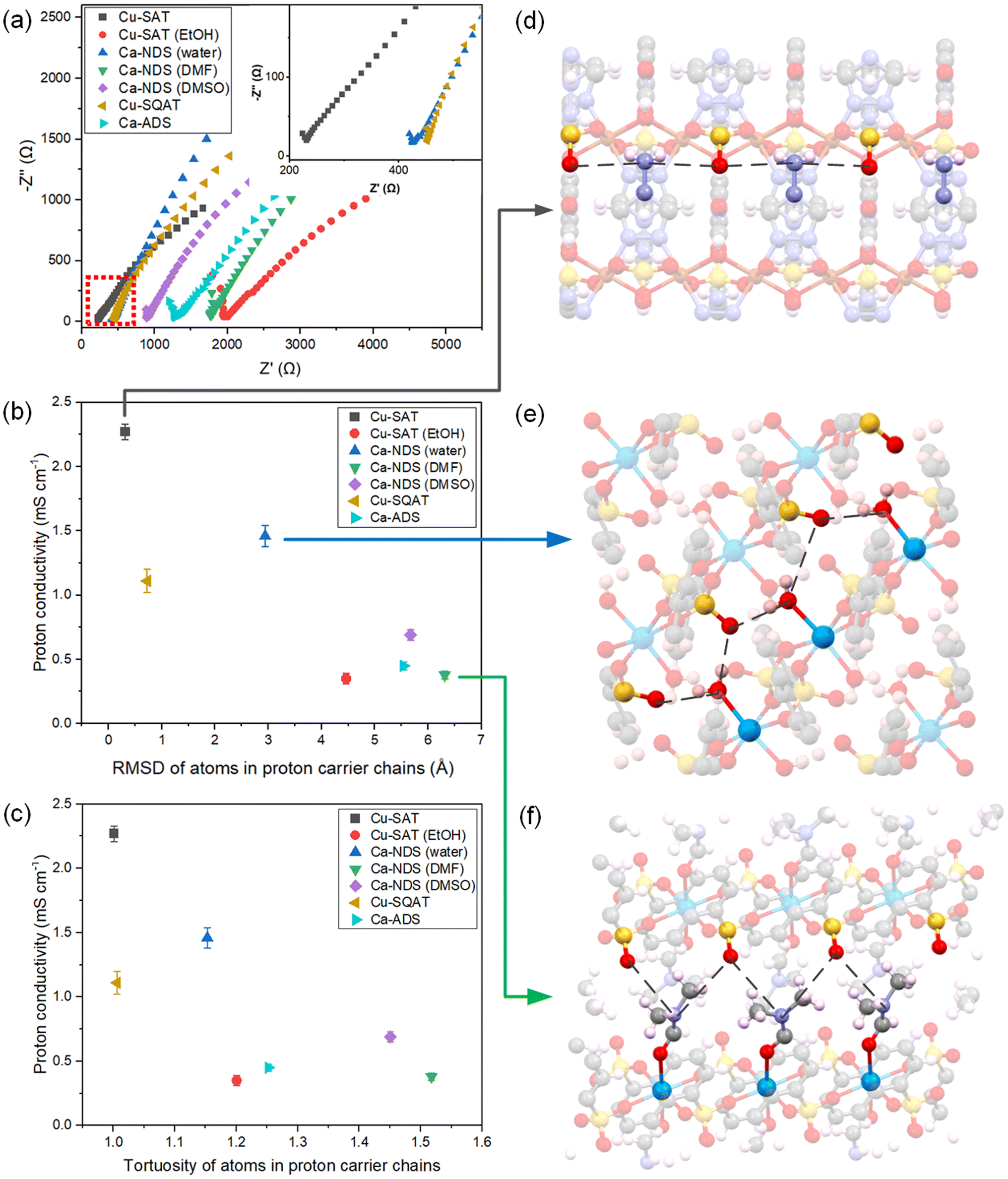 | ||
| Fig. 5 (a) EIS Nyquist plots for seven CPs synthesised in this work, prepared as pellets and measured at 80 °C and 95% RH. Correlation of recorded proton conductivities with (b) the RMSD and (c) the tortuosity of atoms in hydrogen bonding network within the synthesised CPs, determined from SC-XRD structures. The error bars indicate one standard deviation. Note: tortuosity is the ratio of the full circuitous path-length along the chain to the distance between its ends. Illustration of the hydrogen bonding networks in (d) Cu-SAT, (e) Ca-NDS (water) and (f) Ca-NDS (DMF). The black dashed line marks the hydrogen bonding network between adjacent electronegative species. | ||
As Cu-SAT, Ca-NDS (water) and Cu-SQAT showed the most promising proton conductivities, temperature-dependent EIS measurements were used to estimate activation energies for proton transport (Fig. S35†). The activation energy Ea of Cu-SAT pellet was determined to be 62.3 ± 2.5 kJ mol−1 or 0.65 ± 0.03 eV (uncertainties given as the standard error), the Ea of the Ca-NDS (water) pellet was determined to be 65.26 ± 4.2 kJ mol−1 or 0.68 ± 0.04 eV, and the Ea of the Cu-SQAT pellet was determined to be 77.3 ± 5.0 kJ mol−1 or 0.81 ± 0.05 eV. These activation energies suggest that in pellet form these materials exhibit a predominantly vehicle mechanism (Ea > 0.4 eV) for proton transport, where the proton travels as a diffusing protonated group such as H3O+.62 In the pellet form, the overall transport behaviour contains contributions from both the transport within crystals and along or between grains.
In order to further probe the structural and chemical origins of the spread of conductivities for these NDS- and ADS-based CPs, we return to the single-crystal structures. Given the prevailing understanding of the role of hydrogen bond donors and acceptors in MOF and CP proton conduction pathways, we have isolated the 1D shortest path routes through the seven synthesised CPs. By measuring the distances between proton carriers (taken as the most electronegative species along the chain), we have then extracted a root mean squared displacement (RMSD) as a general descriptor of the tortuosity of this hydrogen bonding and proton transport pathway. Fig. 5b plots the recorded proton conductivities against the RMSD, showing more linear hydrogen bonding networks (smaller RMSD values) are correlated with higher proton conductivities. Fig. 5c likewise depicts a consistent correlation between proton conductivities and the tortuosity of the chain, alternatively taken as the ratio of the full circuitous path-length along the chain to the distance between its ends. A clear trend emerges across the set of diverse structures exhibiting pronounced variation in the RMSD measure of the tortuosity, depicted in the unit cells in Fig. 5d–f. The pathways mapped for all samples are shown in Fig. S36.†
Features specific to individual materials, such as differences in the electronegativity of the species involved in the hydrogen bonding network, differences in spacing between the 2D layers in each structure, and differences in the relative offset or packing between layers, may also impact proton conductivity. We note, however, that these structural features are intrinsically interlinked with the tortuosity of the lowest energy configuration. That is, species with stronger interactions between hydrogen bonding donors and acceptors are expected to favour more linear chains and, consequently, narrower gaps between layers. Cu-SQAT and Ca-ADS distinct network structures (a hydrogen bonding network and a 1D coordination polymer, respectively) and incorporate additional carbonyl moieties in their quinone functional groups, and Cu-SAT (EtOH) exhibits significantly corrugated layers in contrast to the quasi-planar 2D sheets observed in the other structures. Such differences may explain why these compounds show a deviation to lower conductivity relative to the trend in the other 2D arenedisulfonate coordination polymers. While there are undoubtedly numerous contributions to the overall conductivity in the pellet, including the specific chemical interactions beyond purely structural variations63 and grain boundary pathways,64 the RMSD provides a practically useful classifier for proton conductivity within this set of chemically and structurally similar sulfonate CPs. Together, by experimentally deriving a set of CPs with sufficient chemical and structural inter-comparability, this analysis identifies a defining structure–function relationship for explaining and predicting variations in the proton conductivity of 2D sulfonate CPs.
To further demonstrate the utility of these coordination polymers for proton conducting membrane applications, Ca-NDS (water) and Cu-SQAT based MMMs were fabricated using a polymer matrix comprised of PVP and PVDF, two polymers that themselves show low proton conductivity but offer a favourable blend of hydrophilicity (PVP) and mechanical and thermal stability (PVDF).65,66 This approach enables enhancing performance of membranes through the coordination polymer conductivity using alternative polymers to Nafion associated with high production costs and manufacturing hazards.67,68 The choice of Ca-NDS (water) and Cu-SQAT MMMs extends and complements our previous examination of Cu-SAT MMMs28 as these sulfonate coordination polymers exhibit the next two top-performing pellet proton conductivities of the series considered here.
Fig. 6 shows cryo-SEM images of the membranes in the fully-hydrated state, used for accounting for thickness changes affected by swelling on hydration under electrochemical testing under high relative humidities (thicknesses of 108 μm and 117 μm for the Ca-NDS (water)-MMM and for the Cu-SQAT-MMM, respectively). Fig. S37 and S38† present EDS mapping of the membranes in cross section, confirming the dispersion of Ca-NDS (water) and Cu-SQAT particles throughout the membrane. Fig. 6c presents EIS results of Ca-NDS (water)-MMM and Cu-SQAT-MMM, showing proton conductivities of Ca-NDS (water)-MMM and Cu-SQAT-MMM of 0.91 ± 0.04 and 0.68 ± 0.03 mS cm−1 at 80 °C and 95% RH, respectively. The proton conductivity of Cu-SAT based MMM, reported in our previous work,28 is 1.34 ± 0.05 mS cm−1. As such, the MMMs prepared using Ca-NDS (water) and Cu-SQAT follow the trend in pellet conductivities. Moreover, all three arenedisulfonate coordination polymer based MMMs (Cu-SAT, Ca-NDS (water) and Cu-SQAT) made in our work offer favourable conductivities in comparison with other recently reported MOF-based MMMs.44,69–72 Critically, record conductivity is not the sole objective for optimizing these materials. Notably, reduced toxic solvent and a simplified set of precursors used in the preparation of Ca-NDS offers green chemical advantages for these MMMs while offering comparable proton conductivities to Cu-SAT prepared using DMF. The crystal structure trends identified (Fig. 5) point to transferability through to membrane integration for improving materials selection and design for scalable MMMs in fuel cells and related technologies.
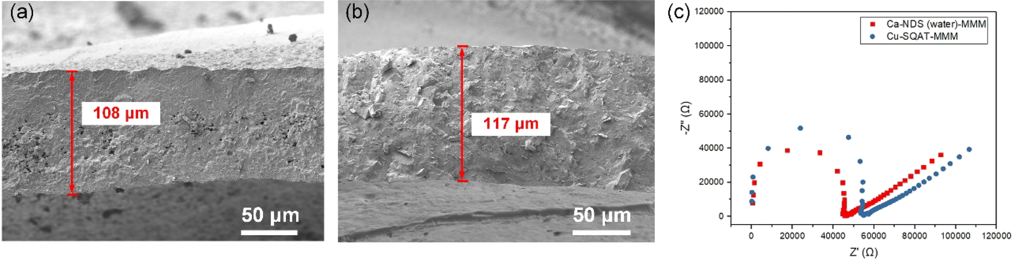 | ||
| Fig. 6 (a) Cryo-SEM micrographs of cross section of the fully hydrated (a) Ca-NDS (water)-MMM and (b) Cu-SQAT-MMM membranes, and (c) EIS Nyquist plots for Ca-NDS (water)-MMM and Cu-SQAT-MMM membranes measured at 80 °C and 95% RH. | ||
4. Conclusions
In summary, we have used NDS and ADS sulfonate ligands to synthesise a series of Cu2+ and Ca2+ CPs. By varying the solvent for a series of NDS-based structures, we have now reported unit cells for Cu-SAT (EtOH), Ca-NDS (DMF), and Ca-NDS (DMSO), all exhibiting a consistent 2D sheet structural motif. By using the ADS ligand, a hydrogen bonded network incorporating sulfonate, quinone, and aminotriazolate moieties named Cu-SQAT and a 1D CP built from Ca2+ denoted Ca-ADS have also been reported. We have assessed these materials' proton conductivity properties, of interest in fuel cell applications: Cu-SAT, Ca-NDS (water) and Cu-SQAT show promising proton conductivities of 2.27 ± 0.06 mS cm−1, 1.46 ± 0.08 mS cm−1 and 1.11 ± 0.09 mS cm−1 at 80 °C and 95% relative humidity, respectively. And the proton conductivities of Cu-SAT, Ca-NDS (water) and Cu-SQAT based MMMs present a similar order of magnitude to that their pellet samples. Finally, we have established an experimental structure–function relationship linking the tortuosity of the hydrogen bonding pathway with proton conductivities across the synthesised sulfonate CPs. These findings outline structural design principles for sulfonate CPs and likely wider CP and MOF materials for optimising proton conductivity systematically.Data availability
Crystallographic data for 2336802, 2336803, 2336804, 2336805, and 2336805 have been deposited at the CCDC. The data associated with this paper are openly available from the University of Leeds Data Repository at https://doi.org/10.5518/1502.Conflicts of interest
There are no conflicts to declare.Acknowledgements
CS acknowledges financial support from the China Scholarship Council (CSC) (Grant No. 202006630025). SMC acknowledges support from the Royal Society (RGS\R2\212076) and UK Research and Innovation (EP/Y024583/1, project AMICI selected by the European Research Council and funded by UKRI) and the Engineering and Physical Sciences Research Council (EP/V028855/1). We thank Karine Alves Thorne, Adrian Cunliffe and Mohammed Javed for their assistance with CHNS, TGA and FTIR analysis. We acknowledge support from the Henry Royce Institute (EPSRC grants: EP/P022464/1, EP/R00661X/1), which funded the VXSF Facilities (https://engineering.leeds.ac.uk/vxsf) within the Bragg Centre for Materials Research at Leeds. We thank the Diamond Light Source for access and support in the use of the electron Physical Sciences Imaging Centre (MG33373).References
- R. Sahoo, S. C. Pal and M. C. Das, ACS Energy Lett., 2022, 7, 4490–4500 CrossRef CAS.
- W. Xu, W. Xue, H. Huang, J. Wang, C. Zhong and D. Mei, Appl. Catal., B, 2021, 291, 120129 CrossRef CAS.
- D. Yang and B. C. Gates, ACS Catal., 2019, 9, 1779–1798 CrossRef CAS.
- X. L. Hu, K. Wang, X. Li, Q. Q. Pan and Z. M. Su, New J. Chem., 2020, 44, 1249–1252 Search PubMed.
- H. Li, K. Wang, Y. Sun, C. T. Lollar, J. Li and H. C. Zhou, Mater. Today, 2018, 21, 108–121 CrossRef CAS.
- Y. Chen, L. Zheng, Y. Fu, R. Zhou, Y. Song and S. Chen, RSC Adv., 2016, 6, 85917–85923 RSC.
- X. Zhao, G. Niu, H. Yang, J. Ma, M. Sun, M. Xu, W. Xiong, T. Yang, L. Chen and C. Wang, CrystEngComm, 2020, 22, 3588–3597 RSC.
- S. Tai, W. Zhang, J. Zhang, G. Luo, Y. Jia, M. Deng and Y. Ling, Microporous Mesoporous Mater., 2016, 220, 148–154 CrossRef CAS.
- Y.-K. Seo, G. Hundal, I. T. Jang, Y. K. Hwang, C.-H. Jun and J.-S. Chang, Microporous Mesoporous Mater., 2009, 119, 331–337 CrossRef CAS.
- A. Grigoropoulos, A. I. McKay, A. P. Katsoulidis, R. P. Davies, A. Haynes, L. Brammer, J. Xiao, A. S. Weller and M. J. Rosseinsky, Angew Chem. Int. Ed. Engl., 2018, 57, 4532–4537 CrossRef CAS PubMed.
- Z. Mai and D. Liu, Cryst. Growth Des., 2019, 19, 7439–7462 CrossRef CAS.
- X. Jiang, H. Li, J. Xiao, D. Gao, R. Si, F. Yang, Y. Li, G. Wang and X. Bao, Nano Energy, 2018, 52, 345–350 CrossRef CAS.
- B. Huang, Y. Li and W. Zeng, Nano Futures, 2022, 6, 032003 CrossRef CAS.
- S. Wang, M. Gong, X. Han, D. Zhao, J. Liu, Y. Lu, C. Li and B. Chen, ACS Appl. Mater. Interfaces, 2021, 13, 11078–11088 CrossRef CAS PubMed.
- S. S. Iremonger, J. Liang, R. Vaidhyanathan, I. Martens, G. K. Shimizu, T. D. Daff, M. Z. Aghaji, S. Yeganegi and T. K. Woo, J. Am. Chem. Soc., 2011, 133, 20048–20051 CrossRef CAS PubMed.
- S. S. Iremonger, J. Liang, R. Vaidhyanathan and G. K. Shimizu, Chem. Commun., 2011, 47, 4430–4432 RSC.
- S. Horike, D. Umeyama, M. Inukai, T. Itakura and S. Kitagawa, J. Am. Chem. Soc., 2012, 134, 7612–7615 CrossRef CAS PubMed.
- A. P. Côté and G. K. H. Shimizu, Coord. Chem. Rev., 2003, 245, 49–64 CrossRef.
- F. Yang, G. Xu, Y. Dou, B. Wang, H. Zhang, H. Wu, W. Zhou, J.-R. Li and B. Chen, Nat. Energy, 2017, 2, 877–883 CrossRef CAS.
- R. Moi, A. Ghorai, S. Banerjee and K. Biradha, Cryst. Growth Des., 2020, 20, 5557–5563 CrossRef CAS.
- H. A. Patel, N. Mansor, S. Gadipelli, D. J. Brett and Z. Guo, ACS Appl. Mater. Interfaces, 2016, 8, 30687–30691 CrossRef CAS PubMed.
- S.-N. Zhao, X.-Z. Song, M. Zhu, X. Meng, L.-L. Wu, S.-Y. Song, C. Wang and H.-J. Zhang, Dalton Trans., 2015, 44, 948–954 RSC.
- P. Ramaswamy, R. Matsuda, W. Kosaka, G. Akiyama, H. J. Jeon and S. Kitagawa, Chem. Commun., 2014, 50, 1144–1146 RSC.
- G. Zhang and H. Fei, Top. Curr. Chem., 2019, 377, 32 CrossRef PubMed.
- J. Cai, Coord. Chem. Rev., 2004, 248, 1061–1083 CrossRef CAS.
- J. Cai, C. H. Chen, C. Z. Liao, X. L. Feng and X. M. Chen, Acta Crystallogr., Sect. B: Struct. Sci., Cryst. Eng. Mater., 2001, 57, 520–530 CrossRef CAS PubMed.
- D. K. Maity, K. Otake, S. Ghosh, H. Kitagawa and D. Ghoshal, Inorg. Chem., 2017, 56, 1581–1590 CrossRef CAS PubMed.
- C. Sun, M. Barton, C. M. Pask, M. Edokali, L. Yang, A. J. Britton, S. Micklethwaite, F. Iacoviello, A. Hassanpour, M. Besenhard, R. Drummond-Brydson, K.-J. Wu and S. M. Collins, Chem. Eng. J., 2023, 474, 145892 CrossRef CAS.
- J. Zhang, G. B. White, M. D. Ryan, A. J. Hunt and M. J. Katz, ACS Sustain. Chem. Eng., 2016, 4, 7186–7192 CrossRef CAS.
- P. Marino, P. R. Donnarumma, H. A. Bicalho, V. Quezada-Novoa, H. M. Titi and A. J. Howarth, ACS Sustain. Chem. Eng., 2021, 9, 16356–16362 CrossRef CAS.
- T. Kundu, M. Wahiduzzaman, B. B. Shah, G. Maurin and D. Zhao, Angew Chem. Int. Ed. Engl., 2019, 58, 8073–8077 CrossRef CAS PubMed.
- G. Wen, B. Liu, D. Liu, F. Wang, L. Li, L. Zhu, D. Song, C. Huang and Y. Wang, Inorg. Chim. Acta, 2020, 502, 119296 CrossRef CAS.
- Q. Yang, X. Chen, Z. Chen, Y. Hao, Y. Li, Q. Lu and H. Zheng, Chem. Commun., 2012, 48, 10016–10018 RSC.
- W. Fan, X. Zhang, Z. Kang, X. Liu and D. Sun, Coord. Chem. Rev., 2021, 443, 213968 CrossRef CAS.
- O. M. Yaghi, M. O'Keeffe, N. W. Ockwig, H. K. Chae, M. Eddaoudi and J. Kim, Nature, 2003, 423, 705–714 CrossRef CAS PubMed.
- A. E. Platero-Prats, M. Iglesias, N. Snejko, Á. Monge and E. Gutiérrez-Puebla, Cryst. Growth Des., 2011, 11, 1750–1758 CrossRef CAS.
- F. Gándara, A. García-Cortés, C. Cascales, B. Gómez-Lor, E. Gutiérrez-Puebla, M. Iglesias, A. Monge and N. Snejko, Inorg. Chem., 2007, 46, 3475–3484 CrossRef PubMed.
- G. M. Sheldrick, Acta Crystallogr., Sect. A: Found. Adv., 2015, 71, 3–8 CrossRef PubMed.
- G. M. Sheldrick, Acta Crystallogr., Sect. C: Struct. Chem., 2015, 71, 3–8 Search PubMed.
- F. de La Peña, E. Prestat, V. Tonaas Fauske, P. Burdet, J. Lähnemann, T. Furnival, P. Jokubauskas, M. Nord, T. Ostasevicius, K. E. MacArthur, D. N. Johnstone, M. Sarahan, T. Aarholt, J. Taillon, V. Migunov, A. Eljarrat, J. Caron, T. Poon, S. Mazzucco, C. Francis, B. Martineau, S. Somnath, T. Slater, N. Tappy, M. Walls, N. Cautaerts and F. Winkler, Hyperspy/Hyperspy: Release v1.6.5, Zenodo, 2021, DOI:10.5281/zenodo.5608741.
- D. N. Johnstone, P. Crout, J. Laulainen, S. Høgås, B. Martineau, T. Bergh, S. Smeets, C. Francis, Eirik Opheim, E. Prestata, S. Collins, M. Danaie, T. Furnival, H. W. Ånes, J. Morzy, A. Iqbal, T. Doherty, M. von Lany, T. Ostasevicius, R. Tovey and E. Jacobsen, Pyxem/Pyxem: Pyxem 0.11.0, Zenodo, 2020, DOI:10.5281/zenodo.3831473.
- S. M. Rezaei Niya and M. Hoorfar, J. Power Sources, 2013, 240, 281–293 CrossRef CAS.
- L. Ding, H. Zou, J. Lu, H. Liu, S. Wang, H. Yan and Y. Li, Inorg. Chem., 2022, 61, 16185–16196 CrossRef CAS PubMed.
- L. X. Xie, Z. J. Ye, X. D. Zhang and G. Li, J. Solid State Chem., 2022, 311, 123154 CrossRef CAS.
- M. Mamlouk, P. Ocon and K. Scott, J. Power Sources, 2014, 245, 915–926 CrossRef CAS.
- G. Shi, W. Xu, J. Wang, Y. Yuan, S. Chaemchuen and F. Verpoort, J. CO2 Util., 2020, 39, 101177 CrossRef CAS.
- Q. Liu, J. Li, Z. Zhou, J. Xie and J. Y. Lee, Sci. Rep., 2016, 6, 19593 CrossRef PubMed.
- D. Liu, Z. Jin and Y. Bi, Catal. Sci. Technol., 2017, 7, 4478–4488 RSC.
- P. Gobbo, Z. Mossman, A. Nazemi, A. Niaux, M. C. Biesinger, E. R. Gillies and M. S. Workentin, J. Mater. Chem. B, 2014, 2, 1764–1769 RSC.
- L. Zhong and S. F. Parker, R. Soc. Open Sci., 2018, 5, 181363 CrossRef PubMed.
- M. Staufer, U. Birkenheuer, T. Belling, F. Nörtemann, N. Rösch, W. Widdra, K. L. Kostov, T. Moritz and D. Menzel, J. Chem. Phys., 2000, 112, 2498–2506 CrossRef CAS.
- Y. Ishida, T. Togashi, K. Yamamoto, M. Tanaka, T. Kiss, T. Otsu, Y. Kobayashi and S. Shin, Rev. Sci. Instrum., 2014, 85, 123904 CrossRef CAS PubMed.
- Y. Ji, X. Yang, Z. Ji, L. Zhu, N. Ma, D. Chen, X. Jia, J. Tang and Y. Cao, ACS Omega, 2020, 5, 8572–8578 CrossRef CAS PubMed.
- N. Majoul, S. Aouida and B. Bessaïs, Appl. Surf. Sci., 2015, 331, 388–391 CrossRef CAS.
- D. Grime and I. M. Ward, Trans. Faraday Soc., 1958, 54, 959–971 RSC.
- G. Wulff, Z. Kristallogr. - Cryst. Mater., 1901, 34, 449–530 CrossRef CAS.
- E. Ringe, R. P. Van Duyne and L. D. Marks, J. Phys. Chem. C, 2013, 117, 15859–15870 CrossRef CAS.
- L. Liu, Z. Chen, J. Wang, D. Zhang and Y. Han, Nat. Chem., 2019, 11, 1 CrossRef.
- D. N. Johnstone, F. C. N. Firth, C. P. Grey, P. A. Midgley and S. M. Collins, J. Am. Chem. Soc., 2020, 142, 13081–13089 CrossRef CAS PubMed.
- Z. Guo, Y. Zhang, J. Liu, B. Han and G. Li, New J. Chem., 2021, 45, 16971–16977 RSC.
- H. Zhao, Z. H. Du, C. Y. Mu and G. Li, J. Solid State Chem., 2022, 315, 123550 CrossRef CAS.
- J. T. W. Wang and S. L. C. Hsu, Electrochim. Acta, 2011, 56, 2842–2846 CrossRef CAS.
- A. Gupta, S. Goswami, S. M. Elahi and S. Konar, Cryst. Growth Des., 2021, 21, 1378–1388 CrossRef CAS.
- K. Zhang, G. H. Wen, S. S. Bao, L. Q. Wu and J. G. Jia, ACS Appl. Energy Mater., 2020, 3, 8198–8204 CrossRef CAS.
- L. Fu, N. A. Hashim, Y. Liu, M. Abed and K. Li, J. Membr. Sci., 2011, 375, 1–27 CrossRef.
- Y. Zhang, J. Li, L. Ma, W. Cai and H. Cheng, Energy Technol., 2015, 3, 675–691 CrossRef CAS.
- N. A. Nazir, N. Kim, W. G. Iglesias, A. Jakli and T. Kyu, Polymer, 2012, 53, 196–204 CrossRef CAS.
- M. A. Hickner, H. Ghassemi, Y. S. Kim, B. R. Einsla and J. E. McGrath, Chem. Rev., 2004, 104, 4587–4612 CrossRef CAS PubMed.
- M. Rautenberg, B. Bhattacharya, C. Das and F. Emmerling, Inorg. Chem., 2022, 61, 10801–10809 CrossRef CAS PubMed.
- Y. L. Bao, J. Y. Zheng, H. P. Zheng, G. D. Qi, J. R. An, Y. P. Wu, Y. L. Liu, W. W. Dong, J. Zhao and D. S. Li, J. Solid State Chem., 2022, 310, 123070 CrossRef CAS.
- S. Luo, N. Deng, H. Wang, Q. Zeng, Y. Li, W. Kang and B. Cheng, Chem. Eng. J., 2023, 474, 145683 CrossRef CAS.
- R. L. Liu, J. Li, Y. L. Zhao, Y. R. Wang, X. H. Fan, G. Li and D. Y. Wang, J. Solid State Chem., 2024, 332, 124557 CrossRef CAS.
Footnote |
| † Electronic supplementary information (ESI) available. CCDC 2336802–2336806. For ESI and crystallographic data in CIF or other electronic format see DOI: https://doi.org/10.1039/d4ta01716a |
| This journal is © The Royal Society of Chemistry 2024 |