DOI:
10.1039/D4TA01042F
(Paper)
J. Mater. Chem. A, 2024,
12, 12762-12776
High-performance flexible solid-state asymmetric supercapacitor with NiCo2S4 as a cathode and a MXene-reduced graphene oxide sponge as an anode†
Received
15th February 2024
, Accepted 23rd April 2024
First published on 3rd May 2024
Abstract
Ti3C2 MXenes have revealed immense potential in energy storage systems. Herein, we report the development of a flexible solid-state asymmetric supercapacitor (ASC) device by assembling spherical NiCo2S4 as a cathode, a MXene-reduced graphene oxide sponge (rGOsp) nanocomposite as an anode, and polyvinyl alcohol (PVA) hydrogel comprising a mixture of 3 M KOH and 0.1 M K4[Fe(CN)6] as an electrolyte cum separating membrane. This device (NiCo2S4//MXene-rGOsp) provides a specific capacitance (CS) of 98 F g−1 (at 4.5 A g−1), coulombic efficiency of ∼99% at 15 A g−1, and CS of ∼95% after 4000 cycles. Moreover, it provides an energy density of 35.75 W h kg−1 at a power density of 3693 W kg−1. This device establishes its mechanical flexibility by exhibiting almost similar performances at various deformed structures. The performance of this flexible NiCo2S4//MXene-rGOsp ASC device is superior to many reported MXene-based supercapacitors. This device is also capable of illuminating a series of LED lights. In conclusion, the results clearly prove the potential of this device in high-performance energy storage applications.
1. Introduction
The deterioration of the sources of traditional fossil fuels is adversely affecting the increasing demand for energy required by emerging markets and developing economies.1 Therefore, ascertaining alternative energy sources has become one of the globally essential quests.2,3 The development of energy storage systems capable of storing energy generated from renewable sources and later efficiently delivering this energy whenever required is becoming a crucial technology that needs to be accomplished. Most fields using cutting-edge technologies, such as defence, transportation, and biomedicine, often require energy storage systems that are capable of delivering high energy density and high power density.4 Among various energy storage and conversion systems, electrochemical energy storage (EES) devices (for example, batteries, fuel cells, and supercapacitors) are leading worldwide.3 Supercapacitor devices have the competence to be used in myriad fields, such as hybrid vehicles, military, uninterruptible power supplies, electronics, aircrafts, smart grids, forklifts, and electronics.4,5 Electrode materials can be classified into two main categories: (i) electric double-layer capacitors (EDLCs) (such as porous carbon, graphene, and graphene oxide) and (ii) pseudocapacitors (e.g., metal oxides, metal sulfides, and LDHs). Reviews are available where the electrochemical activities of different electrode materials have been described.6–8 However, the already available supercapacitors in the market exhibit low energy density (5–10 W h kg−1), which further motivates us to explore other electrochemically active materials to attain the demands for supercapacitors with higher energy density and higher power density.9 Multiple approaches are being explored to advance the performance of supercapacitor devices; for example, employing nanocomposites (having the composition of both EDLCs and pseudocapacitive nanomaterials) as electrode materials, increasing the working potential window by assembling asymmetric devices, and modifying electrolyte systems.10–12 Among these strategies, we explored the preparation of high-performance active electrode materials. Many transition metal sulfides (TMSs) are well-studied as active cathode materials for supercapacitors because of their high electrochemical activity and theoretical specific capacitance.13–15 However, single TMSs have certain limitations, including reduced specific capacity under high current densities and insufficient cycling stability. To effectively address these issues, it is vital to develop mixed metal sulfides consisting of a significantly high number of redox sites, enhanced capacitance, and superior electrical conductivity compared to single transition metal sulfides and transition metal oxides.16 Among TMSs, binary transition metal sulfide electrodes, such as CuCo2S4, CoMoS4, ZnCo2S4, MnCo2S4, and NiCo2S4, exhibit enhanced storage capacity, higher electrical conductivity, accelerated electron/ion diffusion, improved redox characteristics, and superior reversibility, thus resulting in extended cycle life.17 A high theoretical specific capacitance value of 2534 F g−1 of NiCo2S4 has convinced us to explore its synthesis and use as electrode material.18 Hence, in this present work, spherical NiCo2S4 has been synthesized as the active material for the cathode. The morphology of the materials plays a significant role in influencing their electrochemical properties.16 Some studies have been carried out on NiCo2S4 with different morphologies, such as nanorods, nanoplates, urchins, and hollow spheres.19,20 Because of abundant active sites, NiCo2S4 spheres can exhibit enhanced electrochemical activities. In this research, sphere-shaped NiCo2S4 has been synthesized through a single-step solvothermal process and used as the cathode material for supercapacitor application.
After the first time synthesis of two-dimensional (2D) MXene (Ti3C2Tx),21 research has been directed toward its properties and use in various fields such as catalysis, electrochemical energy storage and conversion applications (e.g., batteries, supercapacitors), electromagnetic field shielding, biomedical applications, etc. Ti3C2Tx possesses a layered structure of titanium carbide with –O, –OH, and –F as terminal functional groups. Excellent electrical conductivity, hydrophilic surface, high chemical stability, etc., are impressive properties of MXene. However, compared to the other 2D materials, MXene still suffers from exclusive utilization of its properties for electrochemical reactions (i.e., hindrance in ion transportation from the electrolyte to the electrode) due to the restacking or aggregation of the layers. Therefore, researchers are focusing on improving the performance of MXene.22,23 To overcome this limitation, the combination of MXene with rGOsp has been carried out. 2D MXene consisting of unique properties like hydrophilic and negatively charged surface, open ion transport channels, and high metallic conductivity,24 along with 3D rGOsp structures having a high electrical conductivity and high surface area,25 efficiently enhance the performance of the anode material.
In this work, a flexible all-solid-state ASC device was developed by assembling NiCo2S4 as the cathode material, MXene-rGOsp nanocomposite as the anode material, and PVA/KOH + K4[Fe(CN)6] gel was used as a separator as well as electrolyte. The fabricated all-solid-state NiCo2S4//MXene-rGOsp device exhibited high electrochemical performances like specific capacitance (CS) of 98 F g−1 (at 4.5 A g−1) with an energy density of 35.75 W h kg−1 at a power density of 3693 W kg−1, and retained 95% CS value even after ∼4000 cycles. Furthermore, the solid-state NiCo2S4//MXene-rGOsp ASC device demonstrated its capability to illuminate the LED lights, showing its future scope for practical applications. A prototype of an asymmetric supercapacitor device (2032 button type cell) was assembled, and its performances were evaluated.
2. Materials and methods
2.1. Preparation of the materials
The synthesis routes used to prepare pure NiCo2S4, pure MXene, pure rGOsp, and MXene-rGOsp nanocomposite are depicted in Scheme 1. A one-step hydrothermal technique was used to prepare spherical NiCo2S4 particles.26 A three-step process was employed to prepare the MXene-rGOsp nanocomposite. Step-1: pure Ti3C2Tx was synthesized by an etching process where a mixture of LiF/HCl removed Al layers from the MAX phase (Ti3AlC2). Step 2: pure graphene oxide (GO) was synthesized using Hummer's method. A freeze-drying method was used to prepare a GO sponge (GOsp) from this synthesized GO. This GOsp was then proceeded with hydrazine hydrate to form the pure rGOsp by the reduction process. Step 3: two dispersions were prepared by dispersing pure MXene and rGOsp separately in methanol by sonication. Then, the appropriate amount of these dispersions of MXene and rGOsp were mixed and refluxed for 3 h under magnetic stirring. MXene-rGOsp nanocomposites with desired compositions were obtained by drying after refluxing. The comprehensive synthesis protocols and the details of the techniques that were used for the characterization of the materials are specified in the ESI.†
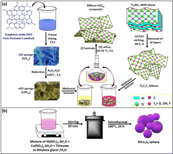 |
| | Scheme 1 Graphical illustration of the synthesis methodologies for the preparation of (a) the MXene, rGOsp, MXene-rGOsp, nanocomposite, and (b) NiCo2S4. | |
2.2. Characterizations of electrochemical properties
2.2.1. 3E-cell system.
The electrochemical tests of MXene, rGOsp, NiCo2S4, and MXene-rGOsp nanocomposite were performed by assembling the 3E-cell setup, comprising the Hg/HgO electrode as the reference electrode, Pt wire as the auxiliary electrode, and a working electrode was prepared using the synthesized materials (MXene, rGOsp, NiCo2S4, and MXene-rGOsp nanocomposite) individually on Ni foam. The synthesized materials were studied in two different aqueous electrolytes (3 M KOH and a mixture of 3 M KOH + 0.1 M K4[Fe(CN)6]) to analyze the effect of different electrolytes on the electrochemical performances of materials. Cyclic voltammetry (CV) and galvanic charge–discharge (GCD) tests were carried out to determine the working potential windows, CS values, etc. Eqn S1 (ref. 27) used for the calculation is provided in ESI.†
2.2.2. Asymmetric supercapacitor device assemblage.
An ASC device was fabricated using 2E-cell, with NiCo2S4 as the cathode and MXene-rGOsp as the anode. A Whatman filter paper dipped in aqueous 3 M KOH + 0.1 M K4[Fe(CN)6] was used as an electrolyte/membrane. The mass ratio of the positive electrode and negative electrode was optimized using a theory of charge balance (q+ = q−) (eqn (S2)†). In the NiCo2S4//MXene-rGOsp ASC device, the mass ratio (m+/m−) was ∼0.31. All the related parameters were calculated using eqn (S1)–(S6)27 provided in the ESI.† A steady working potential window of 1.6 V was finalized after optimizing the CV measurement of the ASC device. The details of the fabrication of flexible all-solid-state ASC devices and 2032-type button cells are described in the ESI.†
3. Result and discussion
3.1. Preparation and characterization of materials
The formation of the NiCo2S4 sphere was carried out using a one-step solvothermal method, and the involved reactions are presented in eqn (1)–(5).28,29 In the aqueous media, the thiourea decomposes to H2S, NH3, and CO2. In the presence of NH3, Ni2+ and Co2+ formed coordination complexes (e.g., [Ni(NH3)4]2+ and [Co(NH3)4]2+) under the hydrothermal condition, and in the presence of S2−, these complexes are converted to NiCo2S4 in the form of a black precipitate. During the reaction, ethylene glycol acts as a stabilizing agent, which limits particle growth and inhibits their agglomeration.| | S![[double bond, length as m-dash]](https://www.rsc.org/images/entities/char_e001.gif) C(NH2)2 + 2H2O → 2NH3 + CO2 + H2S C(NH2)2 + 2H2O → 2NH3 + CO2 + H2S | (1) |
| | | H2S + 2OH− → S2− + 2H2O | (2) |
| | | Ni2+ + 4NH3 → [Ni(NH3)4]2+ | (3) |
| | | Co2+ + 4NH3 → [Co(NH3)4]2+ | (4) |
| | | [Ni(NH3)4]2+ + 2[Co(NH3)4]2+ + 4S2− → NiCo2S4 + 12NH3 | (5) |
First, to synthesize the rGO sponge (rGOsp), GO was prepared using Hummer's method, followed by a freeze-dried method to convert GO to GOsp. Reduction of GOsp resulted in the formation of rGOsp. Ti3C2Tx (MXene) was synthesized by chemical etching of Al layers from Ti3AlC2 using an in situ HF etchant (LiF/HCl),30 and the related reactions are presented as eqn (6)–(9).31 The MXene-rGOsp nanocomposite was synthesized by the incorporation of MXene and rGOsp using a wet impregnation method. Detailed synthesis procedures are given in the ESI.†
| | | LiF(aq) + HCl(aq) → HF(aq) + LiCl(aq) | (6) |
| | | Ti3AlC2(s) + 3HF(aq) → Ti3C2(s) + AlF3(aq) + 3/2H2(g) | (7) |
| | | Ti3C2(s) + 2HF(aq) → Ti3C2F2(s) + H2(g) | (8) |
| | | Ti3C2(s) + 2H2O → Ti3C2(OH)2(s) + H2(g) | (9) |
3.2. Characterisation of as-synthesized materials
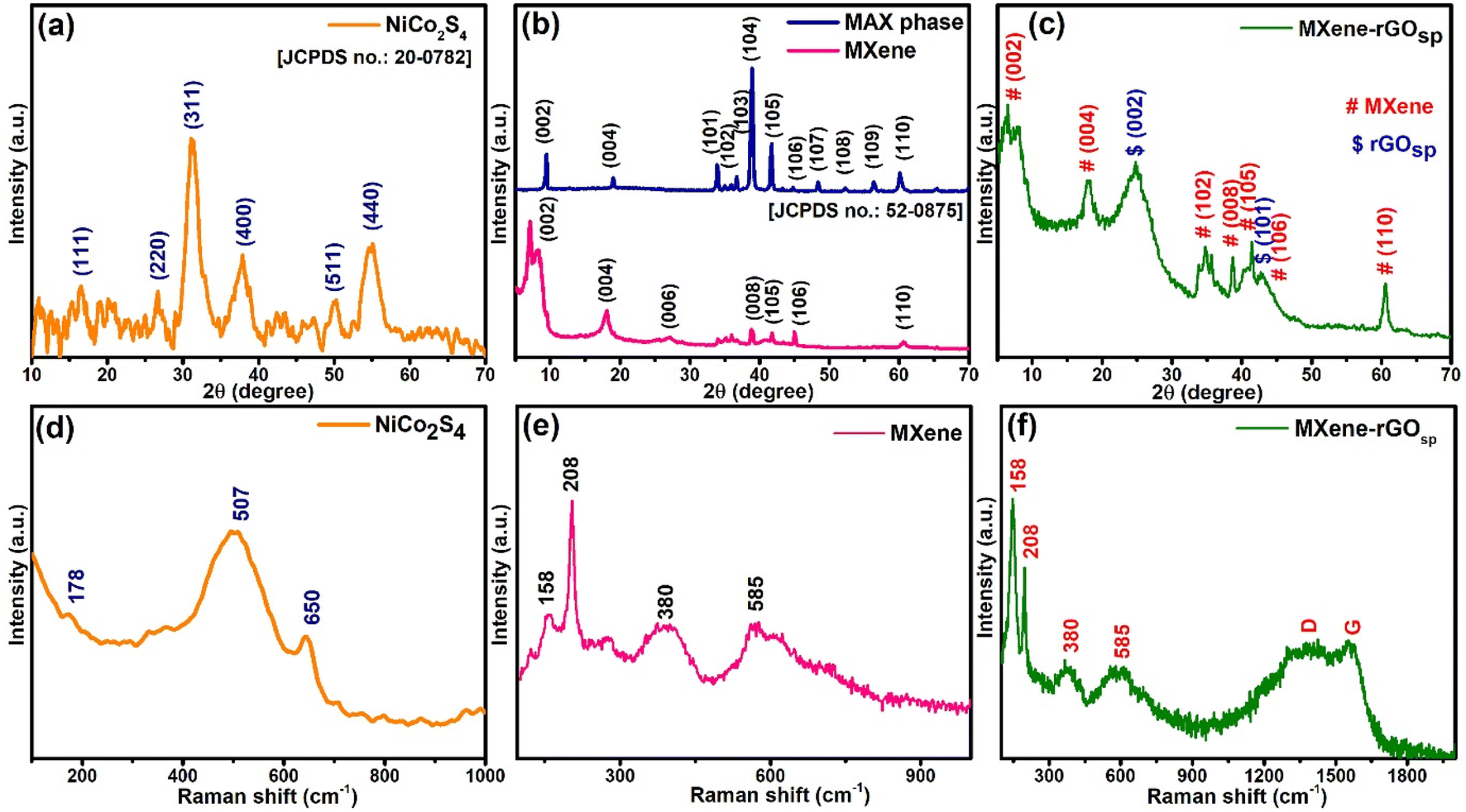
The X-ray diffraction (XRD) technique was conducted to depict the crystal structure of the synthesized materials. The XRD pattern of NiCo2S4 (Fig. 1a) displays distinct peaks compatible with the JCPDS card no. 20-0782 as 2θ values at 16.3, 26.6, 31.3, 38, 50.4, and 55.2° correspond to (111), (220), (311), (400), (511), and (440) planes, respectively.26Fig. 1b presents the comparison graph of XRD patterns of the MAX phase and MXene. In the XRD of MXene, the disappearance of 2θ = 39°, which corresponds to the (104) plane, indicates the etching of Al layers via LiF/HCl treatment during the process of formation of MXene. Also, the other observation was the splitting and shifting of the (002) plane from 2θ = 9.5° (d = 9.3 Å) to 2θ = 8.4° (d = 10.5 Å) and 7.1° (d = 12.1 Å). This indicates the increase in interlayer distance between two layers of MXene because of the elimination of Al layers and weakening of the interaction between the layers.32,33 Other diffraction peaks of MXene were located at 2θ = 18.2°(004), 27.7°(006), 38.7°(008), 41.7°(105), 45°(106), and 60.8°(110). In the XRD pattern of rGOsp, two broad peaks were observed at 2θ values of ∼24.3 and 42.4° concerning (002) and (101) planes, respectively (Fig. S1a†). In the diffraction pattern of the MXene-rGOsp nanocomposites (Fig. 1c and S1b†), all the characteristic peaks of MXene and rGOsp were present. However, characteristic peaks of the (002) plane of MXene were slightly shifted and broadened to lower 2θ values as 8°(11 Å) and 6.3°(14 Å). The shifting of the peak for the (002) plane of MXene towards the lower angle, as well as its broadening, occurred due to the incorporation of rGOsp between the layers of MXene, which led to an increment in the interlayer space.22,23
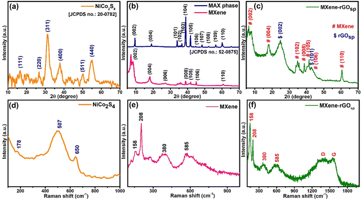 |
| | Fig. 1 XRD patterns of (a) NiCo2S4, (b) MAX phase, MXenes, and (c) MXene-rGOsp. Raman spectra of (d) NiCo2S4, (e) MXenes, (f) MXene-rGOsp nanocomposites. | |
N2 adsorption–desorption analysis of the synthesized materials was performed to estimate their multiple-point Brunauer–Emmett–Teller (BET) surface area and pore volume (Fig. S2†). MXene, rGOsp, and MXene-rGOsp exhibited type-III isotherm with H3 hysteresis, indicating the formation of slit-shape pores due to the aggregation of plate-like particles and the pore network consisting of macropores.34 The specific surface area and pore volume of MXene were 138.04 m2 g−1 and 0.175 cm3 g−1, respectively. For rGOsp, the specific surface area and pore volume values were 303.47 m2 g−1 and 0.424 cm3 g−1, respectively. In the case of MXene-rGOsp nanocomposite, where 50 wt% of MXene was hybridized with 50 wt% of rGOsp, the specific surface area and pore volume became 365.19 m2 g−1 and 0.431 cm3 g−1, respectively. The increase in specific surface area and pore volume in the MXene-rGOsp nanocomposite compared to individual MXene and rGOsp indicated the inhibitory effect of rGOsp on the aggregation or restacking of MXene layers.
In the Raman spectra of NiCo2S4 (Fig. 1d), bands appeared at 650, 507, and 178 cm−1 corresponding to the A1g, F2g, and F2g modes of NiCo2S4, respectively.35,36 Raman spectra of MXene (Fig. 1e) displayed the in-plane Eg vibrational band at ∼158 cm−1 (ω1), the A1g out-of-plane vibrations at 208 cm−1 (ω2) and 585 cm−1 (ω6), and a hump at ∼380 cm−1 due to the heterogeneous termination groups of Ti3C2Tx MXene.37,38 Fig. S3† represents the Raman spectra of rGOsp, which clearly showed D G band peaks at 1345 and 1585 cm−1, respectively.25 The Raman spectra of the MXene-rGOsp nanocomposite (Fig. 1f) display all the characteristic peaks of Ti3C2Tx and rGOsp, indicating their presence in the composite. The Fourier transform infrared spectra (FTIR) were attained to investigate the existence of functional groups or surface bonding in the synthesized materials. The symmetrical stretching and asymmetrical stretching of Ni–S or Co–S vibrations are observed in the FTIR spectra of NiCo2S4 (Fig. S4a†), in which the peaks at 570, 625, and 750 cm−1 are assigned as symmetrical stretching and 1098 cm−1 peak as asymmetrical stretching. Additionally, the band at ∼1630 cm−1 and the broad peak at 3000–3600 cm−1 could be because of the surface-bound –OH groups.39,40 Fig. S4b† displays the FTIR spectra of MXene, rGOsp, and MXene-rGOsp nanocomposite. In the FTIR spectra of MXene, the vibrational bands at (i) 1393 and ∼3700 cm−1 ascribe for –OH groups,38,41,42 (ii) 2970 and 2895 cm−1 correspond to C–H stretching of methyl and methylene groups, which could be due to the presence of some amorphous C in the sample, respectively,43 (iii) 1600 cm−1 (CO) and 672 (Ti–O) cm−1 stretching vibrations,41,44 (iv) two vibrational bands of C–F at 468 and 1060 cm−1.38,43 The FTIR spectra of rGOsp displayed stretching vibrations at ∼3115, 1534, and 1185 cm−1 attributed to the –OH of carboxylic acid, CC, and C–O, respectively. The band at ∼1390 cm−1 could be due to the vibrations of C–H bending/–OH bending of phenol.45,46 The presence of the characteristic bands corresponding to MXene and rGOsp in the MXene-rGOsp nanocomposite confirmed the coexistence of both materials.
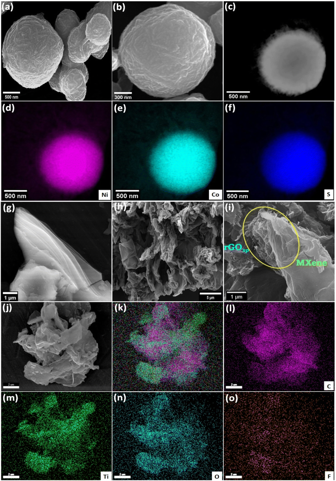
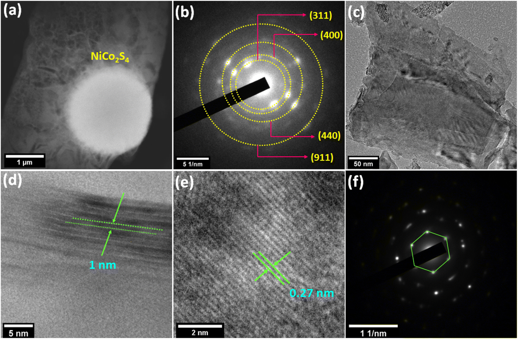
The morphological investigation of the materials was performed using field emission scanning electron microscopy (FESEM). FESEM images of NiCo2S4 reveal its solid spherical microstructure with an average size of ≤1 μm (Fig. 2a). The magnified image of NiCo2S4 displays the wrinkled texture on the surface of a sphere (Fig. 2b). The survey spectrum of energy dispersive X-ray spectroscopy (EDS) (Fig. S5†) and the elemental color mapping (Fig. 2c–f) illustrate that NiCo2S4 spheres are composed of Ni, Co, and S. Fig. 2g shows the FESEM of Ti3C2Tx MXene possessing the nanometer-thin multilayer structure. The FESEM image of a 3D sponge-like morphology of rGOsp is displayed in Fig. 2h. In the MXene-rGOsp nanocomposite (Fig. 2i), the hierarchical arrangement between rGOsp with the layered MXene has been observed, and nanometer thin rGOsp was found to be penetrating within the layers of MXene (see yellow circle in Fig. 2i). In the elemental color mapping of MXene-rGOsp nanocomposite, the uniformly distributed C, Ti, O, and F were observed, indicating the coexistence of MXene and rGOsp (Fig. 2j–o). The existence of C, Ti, O, and F elements in the MXene-rGOsp nanocomposite was also confirmed by the EDS survey spectra (Fig. S6†). The spherical feature of NiCo2S4 was also captured by STEM (Fig. 3a). According to the selected area electron diffraction (SAED) pattern shown in Fig. 3b, the observed diffraction spots confirmed its poly-crystalline nature and are indexed to (311), (400), (440), and (911) planes. Fig. 3c shows the TEM micrograph of the MXene-rGOsp nanocomposite, which confirms its layered nanosheet structure. In the HRTEM of MXene-rGOsp nanocomposite (Fig. 3d), the ∼1 nm interlayer thickness of MXene sheets was observed from the side view, and the lattice fringe distance was 0.27 nm (Fig. 3e). The SAED pattern of the MXene-rGOsp nanocomposite reveals the hexagonal lattice structure of MXene (Fig. 3f).
 |
| | Fig. 2 FESEM image of (a) NiCo2S4 showing its spherical shape, and (b) its magnified image. (c)–(f) color mapping of NiCo2S4. FESEM images of (g) the pure MXene showing its layers, (h) rGOsp showing its sponge-like structure, (i) MXene-rGOsp nanocomposite where the insertion of rGOsp between the layers of the MXene is observed and indicated as a yellow circle, (j)–(o) color mapping of the MXene-rGOsp nanocomposite. | |
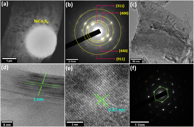 |
| | Fig. 3 (a) STEM image and (b) SAED pattern of NiCo2S4. (c) TEM image, (d and e) HRTEM images, and (f) SAED pattern of the MXene-rGOsp nanocomposite. | |
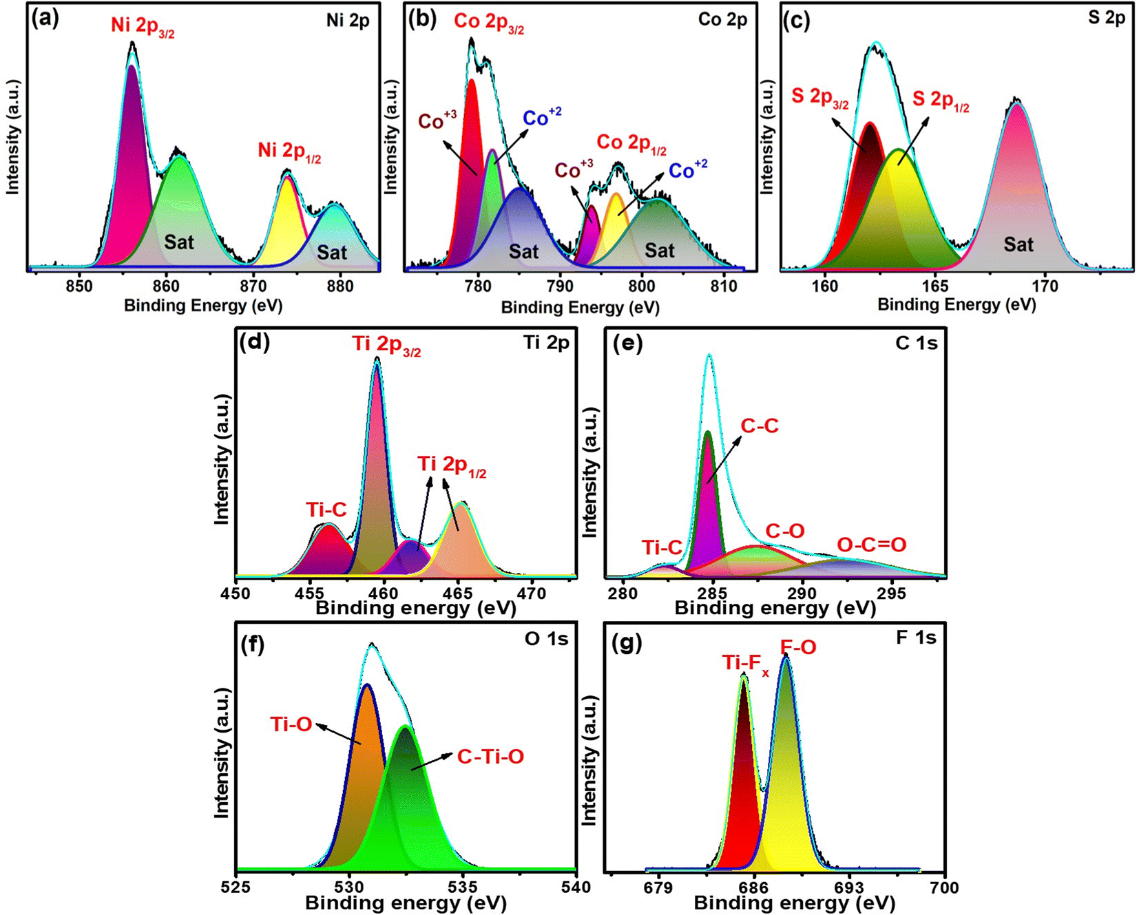
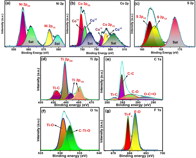
The elemental states of the components present in the synthesized materials were examined by employing XPS analysis. In the XPS survey spectrum of NiCo2S4 (Fig. S7†), the characteristic peaks of Ni 2p, Co 2p, and S 2p were observed, inferring their presence. The Ni 2p XPS spectra (Fig. 4a) were fitted with two spin–orbit doublets at 855.9 eV (Ni 2p3/2), 873.8 eV (Ni 2p1/2), and their two shakeup satellites (Sat) at 861.5, 879.2 eV, respectively. This indicated the presence of Ni in its +2 oxidation state.23,47,48 The high-resolution Co 2p XPS spectrum is presented in Fig. 4b, which was deconvoluted into two spin–orbit doublets (Co 2p3/2, Co 2p1/2) and their respective shakeup satellite peaks. The first pair of doublets were observed at 778.9 and 793.9 eV, and the second pair appeared at 781.5 and 797.05 eV, which were assigned to Co3+ and Co2+, respectively. The splitting energies of both pairs were 15 and 15.55 eV, respectively, which indicated the presence of Co(II) as well as Co(III).19,47 The S 2p spectrum (Fig. 4c) is fitted with two main peaks at 162.05 eV (S 2p3/2), 163.3 eV (S 2p1/2), and one shakeup satellite peak at 168.6 eV, indicating the presence of S2−.36,48 MXene-rGOsp nanocomposite exhibited peaks corresponding to C 1s, O 1s, F 1s, and Ti 2p in its survey spectrum, demonstrating the presence of these elements (Fig. S8†). The deconvoluted Ti 2p spectra (Fig. 4d) were fitted with four peaks at 456.2, 459.5, 461.8, and 465.1 eV, which were assigned to Ti–C, Ti 2 p3/2, and Ti 2 p1/2, respectively.49,50 The deconvoluted C 1s spectra (Fig. 4e) consist of four peaks at 282.2, 284.6, 285.6, and 291.4 eV, credited to Ti–C, C–C, CO, and O–CO bonds, respectively.23,32 The high-resolution O 1s spectra (Fig. 4f) revealed two peaks at 530.7 and 532.4 eV, illustrating the M–O bonds and surface oxygen, respectively.24,51 As for the F 1s spectra presented in Fig. 4g, the peaks at 685.2 and 688.3 eV correspond to Ti–F and F–O bonds, respectively.32,51,52
 |
| | Fig. 4 XPS spectra of NiCo2S4 (a)–(c) and the MXene-rGOsp nanocomposite (d)–(g). | |
3.3. Electrochemical properties
Here, NiCo2S4 was synthesized as an active cathode material and MXene-rGOsp as an anode material to construct an asymmetric supercapacitor device. The electrochemical properties of the as-prepared materials have been characterized in a 3E-cell configuration by employing CV, GCD, and electrochemical impedance spectroscopy (EIS) tests in 3 M KOH electrolyte and also in 3 M KOH and 0.1 M K4[Fe(CN)6] electrolyte.
3.3.1. Cathode material.
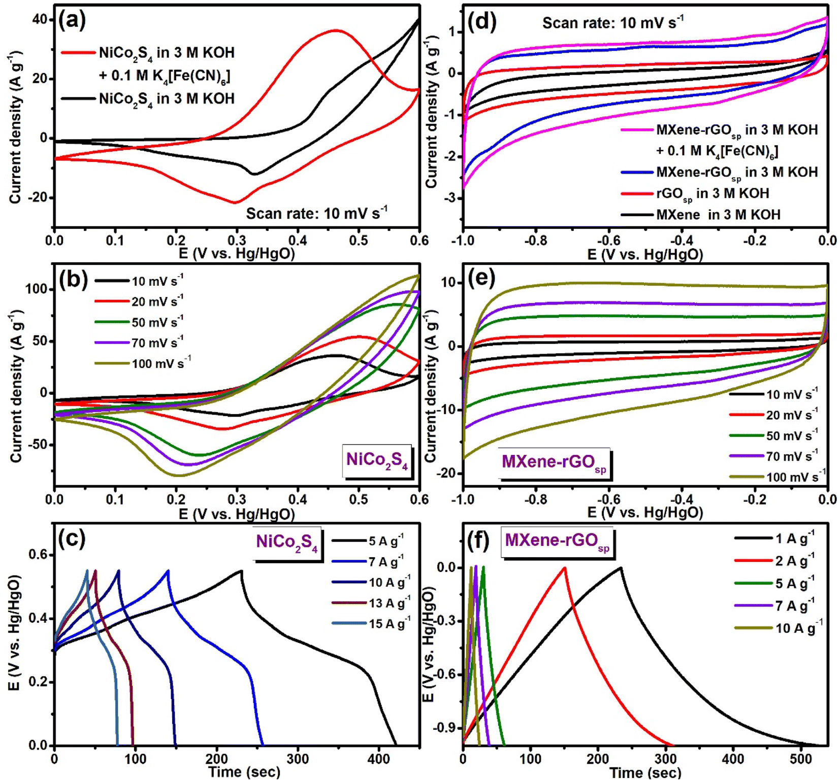
The cyclic voltammogram of NiCo2S4 at a scan rate of 10 mV s−1 in the potential range of 0–0.6 V is presented in Fig. 5a. The observed pair of redox peaks at ∼0.44 V/0.33 V in the CV curve of NiCo2S4 suggested that the capacitance properties were governed by the faradaic redox reaction (eqn (10)–(12)). Even when the scan rate was progressively increased to 100 mV s−1 (Fig. S9a†), the shape of the CV curves remained almost unchanged. However, the oxidation potential was shifted to a more positive potential, along with the shifting of the reduction potential to a lower potential. This phenomenon can occur because of the formation of an overpotential because of the increase in internal diffusion resistance at higher scan rates.47| | | NiCo2S4 + 4OH− ↔ NiSOH + 2CoSOH + SOH− + 3e− | (10) |
| | | NiSOH + OH− ↔ NiSO + H2O + e− | (11) |
| | | CoSOH + OH− ↔ CoSO + H2O + e− | (12) |
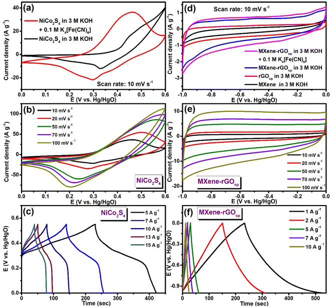 |
| | Fig. 5 (a) CV curves of NiCo2S4 in 3 M KOH and 3 M KOH + 0.1 M K4[Fe(CN)6] at a scan rate of 10 mV s−1. (b) CV curves with the change in scan rates and (c) GCD curves with the change in the current densities of NiCo2S4 in 3 M KOH + 0.1 M K4[Fe(CN)6]. (d) CV curves of the MXene, rGOsp, MXene-rGOsp in 3 M KOH, and MXene-rGOsp in 3 M KOH + 0.1 M K4[Fe(CN)6] at a scan rate of 10 mV s−1. (e) CV curves with the change in scan rates, and (f) GCD curves with the change in the current densities of MXene-rGOsp in 3 M KOH + 0.1 M K4[Fe(CN)6]. | |
Fig. S9b† presents the GCD curves of NiCo2S4 performed at various current densities (from 2 to 10 A g−1) in the voltage window of 0–0.55 V (vs. Hg/HgO).
Furthermore, to improve the electrochemical activity in the system, a redox mediator (K4[Fe(CN)6]) was added to the KOH electrolyte. The comparison of CV curves of NiCo2S4 obtained in 3 M KOH and 3 M KOH + 0.1 M K4[Fe(CN)6] are shown in Fig. 5a. An increase in the integral area of the curve was observed after the addition of 0.1 M K4[Fe(CN)6], which could be because of the presence of an electrochemically reversible [Fe(CN)6]4−/[Fe(CN)6]3− redox couple, which acted as a buffering source of the electron. At the electrode/electrolyte interface, these two reactions cooperate and compensate each other (eqn (13) and (14)), which results in an increase in the rate of the overall redox process.53,54
| | | [Fe(CN)6]3− + e− → [Fe(CN)6]4− | (13) |
| | | [Fe(CN)6]4− → [Fe(CN)6]3− + e− | (14) |
In this electrolyte system, two redox reactions occurred, one on the surface of the electrode material and another in the bulk electrolyte. Fig. 5b shows the CV profile of NiCo2S4 in 3 M KOH + 0.1 M K4[Fe(CN)6], and the current and area of the curves were increased with increasing sweep rate from 10 to 100 mV s−1. GCD curves of NiCo2S4 are presented in Fig. 5c, which indicates its pseudocapacitance nature. Using equation S1,† the values of CS of NiCo2S4 were calculated from the GCD curves. When 3 M KOH aqueous solution was the electrolyte, CS was 554.54 F g−1 at 5 A g−1, and by the addition of 0.1 M K4[Fe(CN)6] to 3 M KOH, CS value was enhanced to 1745.45 F g−1 at 5 A g−1. Fig. S9c† displays the variation of CS with the variation in current density.
The reversible redox peaks were observed in the CV profile of NiCo2S4, which can be due to either a diffusion-controlled redox process resembling battery-type electrodes or pseudocapacitive behavior governed by the adsorption-controlled electrochemical process. To distinguish the charge storage mechanism of NiCo2S4, the relation between the current response and scan rate was used (eqn (15) and (16))55
where
i is the current response at a specific scan rate
ν, and a and
b are the adjustable parameters. In pseudocapacitive electrodes, the current change is directly proportional to the scan rate (
i.e.,
b = 1), whereas, in a diffusion-controlled process, the current response is proportional to the square root of the scan rate (
i.e.,
b = 0.5). For a hybrid system, the value of
b lies between 0.5 and 1.
27 In the case of NiCo
2S
4, the linear rise in current with the square root of the scan rate indicated that its electrochemical response was mainly dictated by the diffusion-controlled process. From the log
![[thin space (1/6-em)]](https://www.rsc.org/images/entities/char_2009.gif) i vs.
i vs. log
ν plot (Fig. S10a
†), the obtained values of
b were 0.5 and 0.49 for NiCo
2S
4 in 3 M KOH and 3 M KOH + 0.1 M K
4[Fe(CN)
6] electrolytes, respectively, which indicated the prominent influence of the diffusion-controlled mechanism of the electrochemical process of NiCo
2S
4 in both the above-mentioned electrolyte systems.
To assess the involvement of capacitive and diffusion to the total current, eqn (17) was used where k1ν indicates the capacitive contribution while k2ν1/2 corresponds to the diffusion-controlled contribution.27,55
| | | i (V)/ν1/2 = k1ν1/2 + k2 | (18) |
where
i is the current at specific voltage V,
k1 and
k2 are constants, and
ν is the scan rate. Fig. S10b
† shows the proportion of capacitive process contributions to the total charge at scan rates of 5 mV s
−1.
Eqn (18) was derived from
eqn (17) to determine the % of the contribution from capacitive and diffusion-controlled processes to the total current. The contribution of these two processes in the energy storage mechanism of NiCo
2S
4 is presented in Fig. S10c
† as a column chart. These results indicated the dominancy of the diffusion contribution to the total current at lower scan rates. With increasing scan rate, the ion transfer rate is enhanced, which limits the contact between electrolyte ions and electrodes. Hence, at a high scan rate, the diffusion mechanism of the electrolyte ions into the electrode material is adversely affected. Therefore, the contribution from the diffusion control process was found to be decreasing with increasing scan rate.
56,57
Further, the electrochemical behavior of NiCo2S4 was examined by employing EIS measurements, and the Nyquist plot was obtained after the circuit fitting, as displayed in Fig. S10d.† In the high-frequency range, a very small semicircle was observed. The calculated RS and RCT values were 0.49 and 0.26 Ω in 3 M KOH electrolyte, respectively, while in 3 M KOH + 0.1 M K4[Fe(CN)6] electrolyte, the RS and RCT values were 0.46 and 0.14 Ω, respectively. In both the electrolyte systems, a very close value of RS indicates that the addition of K4[Fe(CN)6] to the aqueous KOH solution has a negligible effect on the ohmic resistance of the electrolyte, intrinsic electronic resistance of the electrode material and the interfacial resistance between the electrode and electrolyte.5,58 On the other hand, the addition of K4[Fe(CN)6] caused a significant reduction in the RCT value, indicating the enhancement of the charge transfer process because of the presence of this redox mediator in the electrolyte system.
3.3.2. Anode material.
The MXene-rGOsp nanocomposite was synthesized to use as an anode material in this research work. To understand the electrochemical properties of the MXene-rGOsp nanocomposite, the electrochemical measurements of pure MXene and pure rGOsp and MXene-rGOsp nanocomposite were carried out. The study of the cathode material showed the improvement in electrochemical activities on the addition of 0.1 M K4[Fe(CN)6] as a redox additive to 3 M KOH electrolyte; thus, the electrochemical activity of anode materials is also carried out in 3 M KOH as well as 3 M KOH + 0.1 M K4[Fe(CN)6] electrolyte. Fig. S11a and b† display the CV and GCD profiles of pure MXene in 3 M aqueous KOH electrolyte with a −1–0 V (vs. Hg/HgO) potential window. The quasi-rectangular shape of CV curves suggests its pseudocapacitive behavior associated with cation intercalation–deintercalation reaction (eqn (19)) in between the layers of MXene.11,59,60| | | Ti3C2Tx + xK+ + xe− ↔ KxTi3C2Tx | (19) |
Gogotsi and co-workers have already reported that in basic electrolytes, the capacitance of Ti3C2Tx came from the intercalation of cations (e.g., K+) within its layers, and its capacitive behavior was indicated by its rectangular-shaped CV.59 This intercalation process causes the increase in the interlayer spacing of MXene, which was reflected in the XRD pattern of the sample, which underwent 50 CV cycles. In the XRD pattern of the MXene (before CV measurement), the d value of the (002) plane (at 2θ = 8.4°) was 10.5 Å, which increased to 12.6 Å (2θ = 6.9°) for the sample after 50 CV scans (Fig. S11c†).59,61 The CV curves at different scan rates and GCD curves at different current densities of MXene in 3 M KOH + 0.1 M K4[Fe(CN)6] are presented in Fig. S12a and b,† respectively. The Randles–Sevcik plot (Fig. S12c†) indicated that in the case of pure MXene, the peak current was linearly increased when 3 M KOH and 3 M KOH + 0.1 M K4[Fe(CN)6] were used as electrolytes. In the logi vs. logν plot (Fig. S12d†) for pure MXene, the power of the sweep rate was 0.8 and 1 in 3 M KOH and 3 M KOH + 0.1 M K4[Fe(CN)6], respectively, which suggested that adsorption–desorption largely controlled the electrochemical process in both electrolyte systems. However, during electrochemical processes, the agglomeration or restacking of the layers might occur, which could lower the current response. To prevent this agglomeration/restacking of the layers, MXene-rGOsp nanocomposite has been prepared. The CV profile and GCD curves of pure rGOsp are shown in Fig. S13a and b† (in 3 M KOH) and Fig. S13c and d† (in 3 M KOH + 0.1 M K4[Fe(CN)6]). The almost rectangular shape of the CV curve and triangular GCD curves suggested the EDLC nature of the rGO sponge. The CS of 140 F g−1 at 1 A g−1 of rGOsp was obtained when 3 M KOH + 0.1 M K4[Fe(CN)6] was the electrolyte. The almost retention of the shape of the CV and GCD curves obtained at different scan rates indicates its good rate capability. The Randle–Sevcik plots of pure rGOsp (Fig. S14a and b†) indicated an adsorption-controlled electrochemical process at its surface in both 3 M KOH and 3 M KOH + 0.1 M K4[Fe(CN)6] electrolytes. In the MXene-rGOsp nanocomposite, the observed CS was 127 F g−1 at a current density of 1 A g−1 for 30 wt% rGOsp (MXene-rGOsp-1), which increased to 208 F g−1 at 1 A g−1 when the amount of rGOsp was increased to 50% (MXene-rGOsp) in 3 M KOH electrolyte. However, the presence of 70 wt% rGOsp in the nanocomposite (MXene-rGOsp-2) resulted in the reduction of CS to 137 F g−1 at 1 A g−1. This could be owing to the agglomeration of the excessive amount of rGOsp, which can affect the easy ion transport to the electrode material and hence the electrochemical process. Therefore, in the present study, MXene-rGOsp has been chosen as the active anode material. The CV and GCD curves of the different composites are presented in Fig. S15a and b,† respectively. When 0.1 M K4[Fe(CN)6] aqueous solution was added to 3 M KOH solution, the CS of MXene-rGOsp was increased to 296.7 F g−1 at 1 A g−1. The CV profiles of pure MXene, pure rGOsp, and MXene-rGOsp nanocomposite in 3 M KOH and MXene-rGOsp nanocomposite in 3 M KOH + 0.1 M K4[Fe(CN)6] are presented in Fig. 5d when measurements were performed in 3 M KOH + 0.1 M K4[Fe(CN)6] at a scan rate of 10 mV s−1. A significant enhancement of the area under the CV curve due to the addition of 50 wt% rGOsp to 50 wt% MXene (i.e., MXene-rGOsp) was observed, which supports its higher CS than that of pure MXene and rGOsp. The CV profiles and GCD curves of MXene-rGOsp measured in 3 M KOH and 3 M KOH + 0.1 M K4[Fe(CN)6] are shown in Fig. 5e, f, S16a, and b.† In both cases, the quasi-rectangular shape of the CV curves and triangular GCD curves were observed. The profile of CV curves remained nearly the same even with a higher scan rate of 100 mV s−1, which showed its good rate capability. The noticeable features observed from the CV and GCD profiles of pure MXene, pure rGOsp, and MXene-rGOsp were: (i) the order of increase of CS values in both the electrolytes is MXene < rGOsp < MXene-rGOsp, (ii) MXene-rGOsp in 3 M KOH and 3 M KOH + 0.1 M K4[Fe(CN)6] electrolyte retained ∼100% of its capacitance even at a high scan rate of 100 mV s−1, which suggested high rate capability (Fig. S16c and d†). (iii) The logi vs. logν plot of MXene-rGOsp shows that b ≈ 1 (Fig. S17a†). This suggested the kinetic of pseudocapacitance, which indicated an adsorption-controlled electrochemical process. The Randle–Sevcik plot (peak current vs. scan rate) shows a linear trend of peak current increase with increasing scan rate (Fig. S17b†). Fig. S17c and d† show that the electrochemical process of MXene-rGOsp is mainly administered by the capacitive controlled process.
The EIS measurements were conducted to estimate the resistance at the electrode–electrolyte interfaces and the electrochemical kinetics of the charge transfer in the synthesized materials. Fig. S18† represents the Nyquist plots, and the EIS data obtained after the circuit fitting are mentioned in Table S1.† From the EIS data, it can be concluded that MXene-rGOsp nanocomposite shows the lowest RS (0.43 Ω) and RCT (0.66 Ω) values compared to the pure MXene, pure rGOsp, MXene-rGOsp-1, and MXene-rGOsp-2 nanocomposites. As presented, the internal resistance (RS values) of the MXene-based nanocomposites were not affected by the different contents of rGOsp, indicating that the electrochemical reactions are mainly directed by the charge transfer mechanism.25 Amongst the synthesized materials, MXene-rGOsp displayed the lowest RCT value of 0.66 Ω (Table S1†), indicating the lowest charge transfer resistance of the electrolyte–electrode interface between 3 M KOH and MXene-rGOsp. Hence, the appropriate amount of MXene-rGOsp causes the charge transfer process to be faster. As MXene-rGOsp demonstrated its superior electrochemical performance compared to the other synthesized materials, and we have now used it as the active electrode material for the anode to construct a high-performing asymmetric supercapacitor device.
3.3.3. Two-electrode asymmetric supercapacitor device.
To demonstrate the practicability of the prepared MXene-rGOsp nanocomposite as electrode material in the feasible supercapacitor applications, a two-electrode ASC cell was fabricated (NiCo2S4//MXene-rGOsp) using NiCo2S4 spheres as the cathode and the MXene-rGOsp nanocomposite as the anode. The electrodes were separated by a membrane prepared with a Whatman filter paper soaked in a 3 M KOH + 0.1 M K4[Fe(CN)6] solution. Fig. 6a shows the CV curves of MXene-rGOsp (−1–0 V vs. Hg/HgO), NiCo2S4 (0–0.6 V vs. Hg/HgO), and the NiCo2S4//MXene-rGOsp hybrid asymmetric supercapacitor device operating within the working potential window 0–1.6 V at a constant scan rate of 50 mV s−1. The CV profiles of this 2D asymmetric assembly were measured at various potential windows, and a stable working potential window was obtained at 0–1.6 V, and beyond 1.7 V, a sharp peak (indicated as a red circle in Fig. 6b) due to the evolution of oxygen. The shape of the CV curves obtained at different scan rates did not change noticeably with increasing scan rates up to 100 mV s−1 (Fig. 6c), indicating the high rate capability and good reversibility of this ASC. Asymmetric GCD curves were also obtained by changing the potential windows from 1.0 to 1.6 V (Fig. 6d). Fig. 6e shows the GCD curves at varying current densities (4.5–15 A g−1) in the 0–1.6 V potential window. The CS value was 104.6 F g−1 at 4.5 A g−1, which decreased to 64.2 F g−1 when the current density increased to 15 A g−1. The regular nature of these GCD curves reveals its high electrochemical capacitance and reversibility. The coulombic efficiency was found in the range of 88 to 103% with the change in current density. Values of power density and energy density were calculated by eqn S4 and S5† and the relation between them is presented in the Ragone plot of the NiCo2S4//MXene-rGOsp ASC device, as shown in Fig. 6f. The NiCo2S4//MXene-rGOsp ASC device delivered a high energy density of 35.6 W h kg−1 at a power density of 3465 W kg−1 and an energy density of 20.5 W h kg−1 at a high power density of 10760 W kg−1.
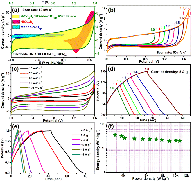 |
| | Fig. 6 (a) CV curves of NiCo2S4 (0–0.6 V), MXene-rGOsp (−1–0 V), and the NiCo2S4//MXene-rGOsp ASC device (0–1.6 V) at a scan rate of 50 mV s−1. (b) CV curves at different operating potential windows in the range of 1.0–1.7 V, (c) CV curves with various scan rates ranging from 10 to 100 mV s−1. (d) GCD curves at different potential windows, (e) GCD curves with the current density changing from 4.5 to 15 A g−1, and (f) Ragone plot of the NiCo2S4//MXene-rGOsp ASC device. | |
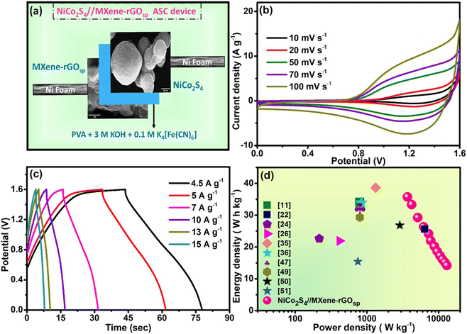
To explore the feasibility in practical applications, an all-solid-state flexible asymmetric supercapacitor device was assembled and comprehensively studied. As graphically illustrated in Fig. 7a, the solid-state NiCo2S4//MXene-rGOsp ASC device was assembled with a gel electrolyte/separator consisting of a mixture of 3 M KOH + 0.1 M K4[Fe(CN)6] embedded in PVA. As shown in CV (Fig. 7b), this asymmetric solid-state device can be operated at high scan rates (10–100 mV s−1) without any shape distortion in the potential window of 0–1.6 V.
 |
| | Fig. 7 (a) Schematic illustration of the assembly of the flexible solid-state NiCo2S4//MXene-rGOsp ASC device. (b) CV profile with various scan rates, (c) GCD profile with different current densities, and (d) Ragone plot of the flexible solid-state NiCo2S4//MXene-rGOsp ASC device compared with some reported works on two-electrode supercapacitor devices. | |
The almost unaffected shape of CV curves and increment of the area under the curves with the increased scan rates owing to faster kinetics indicated the stability of the device. The charge–discharge cycles with various current densities are shown in Fig. 7c. A CS value of 98 F g−1 at a current density of 4.5 A g−1 was observed, which reduced to 36.5 F g−1 when the current density was raised to 15 A g−1. Fig. S19† shows the change in CS values and coulombic efficiency η (%) with changing current densities. The all-solid-state ASC device showed ∼99% coulombic efficiency at 15 A g−1 current density. The Nyquist plot of the device is shown in Fig. S20;† from the high-frequency region, the observed internal and charge transfer resistances are 0.74 and 0.75 Ω, respectively, after the circuit fitting (see inset of Fig. S20†). Moreover, two significant parameters that determine the accessibility of the supercapacitor device are the energy density and the power density, which can be presented by the Ragone plot. The evaluated energy density of 35.75 W h kg−1 at a power density of 3693 W kg−1, and even at a higher power density of 13076 W kg−1, the all-solid-state ASC device still achieved the energy density of 14 W h kg−1. The Ragone plot of the NiCo2S4//MXene-rGOsp device in comparison to other reported supercapacitor devices is shown in Fig. 7d (also see Table S2†).11,22,24,26,35,36,47,49–51 The flexibility of the as-prepared device was also tested by altering its angle to 0°, 90°, 180°, and twist forms. The CV (Fig. 8a) and GCD (Fig. 8b) tests at a scan rate of 50 mV s−1 and current density of 5 A g−1, respectively, were studied with varying angles, and the electrochemical properties were maintained. Further, a long-term cycling stability test of the fabricated all-solid-state NiCo2S4//MXene-rGOsp device was carried out at the current density of 5 A g−1, and it retained ∼95% of the initial CS value while maintaining 99% coulombic efficiency after 4000 cycles, and the ten cycles from the start are shown in the inset of Fig. 8c. XRD and FESEM analyses (Fig. S21(a)–(d)†) of NiCo2S4 and MXene-rGOsp electrode materials after cyclic tests were obtained, which displayed no significant changes in crystal structure and morphology even after ∼4000 cycles.
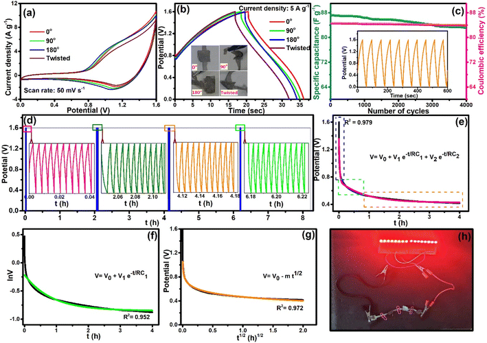 |
| | Fig. 8 (a) CV curves and (b) GCD curves (inset: photographs of the device at 0°, 90°, 180°, and twisted forms) of the flexible solid-state NiCo2S4//MXene-rGOsp ASC device with different physical deformations. (c) Specific capacitance retention and coulombic efficiency versus the number of cycles (inset: first ten GCD cycles). (d) GCD cycles + VHT for 8 h (inset: 10 GCD cycles in-between VHT of 2 h). Self-discharge mechanisms: (e) V vs. t plot, (f) lnV vs. t plot, and (g) V vs. t1/2 plot. (h) Illumination of red LEDs using four flexible solid-state NiCo2S4//MXene-rGOsp ASC devices in series. | |
The voltage holding test (VHT) was conducted to investigate the stability of this device. Fig. 8d presents the VHT for 8 h, which started with 10 cycles of GCD (at 5 A g−1) and continued with the intervening interval of 2 h of voltage holding. The GCD test was carried out in the interval of 2 h of VHT to calculate the specific capacitance (inset of Fig. 8d), and it exhibited the retention of ∼90% of the CS value through 8 h. Further, the self-discharge activity of the device is specified in Fig. 8e; the device was charged to its maximum voltage (1.6 V), and then it was kept under an open circuit potential for 2 h. The device was not completely discharged even after 2 h and retained a potential of ∼0.42 V. Mostly, two types of mechanisms for self-discharge for the supercapacitors can be assumed: (i) potential driven and (ii) diffusion controlled.52 The potential-driven mechanism can be due to the ohmic leakage, and it is further separated as divided potential driven (DPD) or single potential driven (SPD) and expressed as eqn (20) and (21), respectively, and diffusion-driven self-discharging model is expressed as eqn (22).11,52
| | | V = V0 + V1e−t/RC1 + V0e−t/RC2 | (20) |
Here,
V is the variable voltage during self-discharging,
V0 is the initial voltage,
t is the self-discharging time, RC denotes the time constant of the self-discharge, and
m is the diffusion parameter. Firstly, the potential
versus time plot was fitted using the DPD model, which exhibited the mixed potential self-discharge mechanism. Since the asymmetric device was constructed with different electrode materials and nanocomposite, it showed a mixed self-discharge mechanism.
62 Further, the ln
V vs. t plot (
Fig. 8f) and
V vs. t1/2 plot (
Fig. 8g) were fitted using
eqn (21) and
(22), respectively, which exhibited
R-square values of 0.952 and 0.972, respectively. Thus, it can be considered that the constructed all-solid-state NiCo
2S
4//MXene-rGO
sp ASC device has a mixed self-discharged mechanism. Besides, there could also be additional reasons for self-discharge in asymmetric supercapacitors, such as impurities, shuttle effects, functional groups on the electrode surface, overpotential, and charge redistribution.
52Fig. 8h shows the digital image of four NiCo
2S
4//MXene-rGO
sp asymmetric devices, which were connected in series and demonstrated the capability of lighting a panel of 16 red LEDs.
To make a prototype supercapacitor device, a button-cell type (2032 cell) was fabricated (Fig. 9a) using NiCo2S4 as cathode, MXene-rGOsp as anode, and PVA-KOH as electrolyte. The electrochemical measurements were performed at Pilani, India (in December 2023), when the normal room temperature was ∼15 °C. The equivalent circuit resistance of ∼12 Ω was obtained from the EIS measurements of this device, along with a small bulk resistance (∼4 Ω) and low RCT (∼4.49 Ω) (Fig. S22†). This device showed stable and reversible quasi-rectangular-shaped CV curves within the potential window of 0–1.6 V (Fig. S23a†). The nonsymmetric shape of GCD curves obtained at different current densities (ranging from 0.5 to 1 A g−1) implied the pseudo-capacitive behavior (Fig. S23b†). With increasing current density, the coulombic efficiency was increased to ∼100% at 0.5 A g−1 (inset of Fig. S23b†). The cyclic stability test of this 2032 type cell supercapacitor device was performed by the GCD test (Fig. 9b), and the device exhibited ∼90–100 retention of efficiency (inset of Fig. 9b) and ∼85–90% retention of CS even after 4000 cycles (Fig. 9c). This 2032 button type cell supercapacitor device showed a specific power density of ∼643 W kg−1 and specific energy density of ∼5.18 W h kg−1 at 0.05 A g−1 (Ragone plot, Fig. 9d). This device showed its capability of lighting LED lights (inset of Fig. 9d).
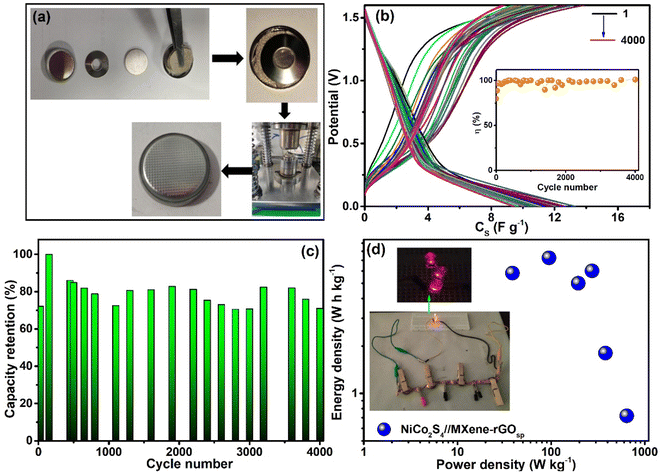 |
| | Fig. 9 (a) Schematic of 2032-type cell preparation, (b) GCD scans with V vs. CS up to 4000 cycles (at 0.5 A g−1) (inset: coulombic efficiency with cycle numbers), (c) retention of capacitance with the cycle number, (d) Ragone plot of the 2032-type cell supercapacitor of NiCo2S4//MXene-rGOsp (inset: LED illumination using four 2032-type cells in series). | |
4. Conclusion
Here, we report a one-step hydrothermal route for synthesizing spherical NiCo2S4. A nanocomposite (MXene-rGOsp) was also prepared, and some of the nanometer-thin sponge-like rGO sheets were placed within the layers of MXene. All the presented electrochemical studies ascertain that the intercalation–deintercalation properties of 2D MXene in the alkaline medium can be enhanced by incorporating rGOsp, which inhibits aggregation/restacking of the MXene sheets and also increases the charge storage capacity of the electrode. NiCo2S4 spheres provide more electrochemical active sites and sustain the reversible redox reaction between the electrolyte and electrode even at a higher current. The all-solid-state flexible ASC device fabricated by combining the anode (MXene-rGOsp) and cathode (NiCo2S4) materials shows excellent electrochemical performance with the CS value (98 F g−1), energy density (35.75 W h kg−1), power density (3693 W kg−1), and cyclic stability (∼95%) and coulombic efficiency (99%) after 4000 cycles. The illumination of LEDs by the NiCo2S4//MXene-rGOsp supercapacitor device significantly indicated its state-of-the-art practical application. This work presents a new prospect in the expansion of MXene-based supercapacitor devices. In the device, the usage of a PVA gel-based electrolyte averts the leakage-related problems associated with the liquid electrolyte-based supercapacitor. The electrochemical performance of this NiCo2S4//MXene-rGOsp all-solid-state supercapacitor is not only superior to most MXene-based ASCs but also exhibits remarkable mechanical flexibility. A prototype of the asymmetric supercapacitor device (button type 2032 cell) was fabricated, which exhibited the energy density of ∼5.18 W h kg−1 at a power density of ∼643 W kg−1, and these values are comparable with commercial supercapacitor devices (energy density of 5–10 W h kg−1). This work can lead to new avenues to accomplish the next generation of all-solid-state supercapacitor devices.
Author contributions
Rajeshvari Samatbhai Karmur: conceptualization, investigation, software, validation, methodology, formal analysis, data curation, writing – original draft, writing – review & editing, visualization. Debika Gogoi: investigation, formal analysis, writing – review & editing. Shrishti Sharma: 2032-type cell study. Manash R. Das: XPS analysis data collection. Anshuman Dalvi: 2032-type cell study supervision. Narendra Nath Ghosh: resources, funding acquisition, supervision, data curation, writing – review & editing.
Conflicts of interest
The authors declare no conflict of interest.
Acknowledgements
N. N. G. acknowledges the Cross-Disciplinary Research Framework (CDRF) scheme BITS Pilani, India (Grant: C1/23/121) for providing financial support. R. S. K. is grateful to CSIR-HRDG, India, for awarding a senior research fellowship (File No. 09/0919(11330)/2021-EMR-I). The authors acknowledge the Central Sophisticated Instrumentation Facility (CSIF), BITS Pilani K Birla Goa Campus, for providing Raman spectroscopy, FESEM, and EDX facilities. The authors convey their sincere gratitude to Ms Mamta and the Department of Chemical Engineering, BITS Pilani, K Birla Goa Campus, for helping with the BET experiment. Also, the authors appreciate IIT Hyderabad for the HRTEM and SAED analysis facilities and CSIR-North East Institute of Science and Technology, Jorhat, for XPS measurements.
References
- R. Morya, T. Raj, Y. Lee, A. Kumar Pandey, D. Kumar, R. Rani Singhania, S. Singh, J. Prakash Verma and S.-H. Kim, Bioresour. Technol., 2022, 366, 128159 CrossRef CAS PubMed
 .
.
- M. R. Lukatskaya, B. Dunn and Y. Gogotsi, Nat. Commun., 2016, 7, 12647 CrossRef PubMed .
- S. S. Siwal, Q. Zhang, N. Devi and V. K. Thakur, Polymers, 2020, 12, 505 CrossRef CAS PubMed .
- S. Natarajan, M. Ulaganathan and V. Aravindan, J. Mater. Chem. A, 2021, 9, 15542–15585 RSC .
- D. Gogoi, R. S. Karmur, M. R. Das and N. N. Ghosh, Sustainable Energy Fuels, 2022, 6, 3599–3610 RSC .
- D. P. Chatterjee and A. K. Nandi, J. Mater. Chem. A, 2021, 9, 15880–15918 RSC .
- J. Huang, Y. Xie, Y. You, J. Yuan, Q. Xu, H. Xie and Y. Chen, Adv. Funct. Mater., 2023, 33, 2213095 CrossRef CAS .
- H. Lv, Q. Pan, Y. Song, X.-X. Liu and T. Liu, Nano-Micro Lett., 2020, 12, 118 CrossRef CAS PubMed .
- P. Simon and Y. Gogotsi, Nat. Mater., 2020, 19, 1151–1163 CrossRef CAS PubMed .
- P. Makkar and N. N. Ghosh, ACS Omega, 2020, 5, 10572–10580 CrossRef CAS PubMed .
- A. K. Tomar, T. Kshetri, N. H. Kim and J. H. Lee, Energy Storage Mater., 2022, 50, 86–95 CrossRef .
- D. Gogoi, P. Makkar, M. R. Das and N. N. Ghosh, ACS Appl. Electron. Mater., 2022, 4, 795–806 CrossRef CAS .
- H. Pan, M. Fan, G. Liu, S. Zeng, R. Wang and H. Zhang, Energy Fuels, 2023, 37, 1396–1403 CrossRef CAS .
- M. R. Pallavolu, S. Vallem, R. R. Nallapureddy, S. Adem and S. W. Joo, ACS Appl. Energy Mater., 2023, 6, 812–821 CrossRef CAS .
- M. S. Javed, H. Lei, J. Li, Z. Wang and W. Mai, J. Mater. Chem. A, 2019, 7, 17435–17445 RSC .
- J. Rehman, K. Eid, R. Ali, X. Fan, G. Murtaza, M. Faizan, A. Laref, W. Zheng and R. S. Varma, ACS Appl. Energy Mater., 2022, 5, 6481–6498 CrossRef CAS .
- P. Kulkarni, S. K. Nataraj, R. G. Balakrishna, D. H. Nagaraju and M. V. Reddy, J. Mater. Chem. A, 2017, 5, 22040–22094 RSC .
- T. Chen, S. Wei and Z. Wang, ChemPlusChem, 2020, 85, 43–56 CrossRef CAS .
- K. Liang, W. He, X. Deng, H. Ma and X. Xu, J. Alloys Compd., 2018, 735, 1395–1401 CrossRef CAS .
- Y. Zhang, M. Ma, J. Yang, C. Sun, H. Su, W. Huang and X. Dong, Nanoscale, 2014, 6, 9824–9830 RSC .
- M. Naguib, M. Kurtoglu, V. Presser, J. Lu, J. Niu, M. Heon, L. Hultman, Y. Gogotsi and M. W. Barsoum, Adv. Mater., 2011, 23, 4248–4253 CrossRef CAS PubMed .
- K. Nasrin, K. Subramani, M. Karnan and M. Sathish, J. Colloid Interface Sci., 2021, 600, 264–277 CrossRef CAS PubMed .
- J. Fu, L. Li, J. M. Yun, D. Lee, B. K. Ryu and K. H. Kim, Chem. Eng. J., 2019, 375, 121939 CrossRef CAS .
- Y. Li, P. Kamdem and X.-J. Jin, J. Alloys Compd., 2021, 850, 156608 CrossRef CAS .
- D. Gogoi, M. R. Das and N. N. Ghosh, ACS Omega, 2022, 7, 11305–11319 CrossRef CAS PubMed .
- F. Wang, G. Li, Q. Zhou, J. Zheng, C. Yang and Q. Wang, Appl. Surf. Sci., 2017, 425, 180–187 CrossRef CAS .
- A. Noori, M. F. El-Kady, M. S. Rahmanifar, R. B. Kaner and M. F. Mousavi, Chem. Soc. Rev., 2019, 48, 1272–1341 RSC .
- P. Phonsuksawang, P. Khajondetchairit, K. Ngamchuea, T. Butburee, S. Sattayaporn, N. Chanlek, S. Suthirakun and T. Siritanon, Electrochim. Acta, 2021, 368, 137634 CrossRef CAS .
- Y.-P. Gao and K.-J. Huang, Chem. - Asian J., 2017, 12, 1969–1984 CrossRef CAS PubMed .
- M. Alhabeb, K. Maleski, B. Anasori, P. Lelyukh, L. Clark, S. Sin and Y. Gogotsi, Chem. Mater., 2017, 29, 7633–7644 CrossRef CAS .
- Y. Chen, H. Yang, Z. Han, Z. Bo, J. Yan, K. Cen and K. K. Ostrikov, Energy Fuels, 2022, 36, 2390–2406 CrossRef CAS .
- R. S. Karmur, D. Gogoi, A. Biswas, C. Prathibha, M. R. Das and N. N. Ghosh, Appl. Surf. Sci., 2023, 623, 157042 CrossRef CAS .
- S. De, C. K. Maity, S. Sahoo and G. C. Nayak, ACS Appl. Energy Mater., 2021, 4, 3712–3723 CrossRef CAS .
- M. Thommes, K. Kaneko, A. V. Neimark, J. P. Olivier, F. Rodriguez-Reinoso, J. Rouquerol and K. S. W. Sing, Pure Appl. Chem., 2015, 87, 1051–1069 CrossRef CAS .
- F. Lu, M. Zhou, W. Li, Q. Weng, C. Li, Y. Xue, X. Jiang, X. Zeng, Y. Bando and D. Golberg, Nano Energy, 2016, 26, 313–323 CrossRef CAS .
- Y. Wen, Y. Liu, T. Wang, Z. Wang, Y. Zhang, X. Wu, X. Chen, S. Peng and D. He, ACS Appl. Energy Mater., 2021, 4, 6531–6541 CrossRef CAS .
- A. Sarycheva and Y. Gogotsi, Chem. Mater., 2020, 32, 3480–3488 CrossRef CAS .
- T. Hu, J. Wang, H. Zhang, Z. Li, M. Hu and X. Wang, Phys. Chem. Chem. Phys., 2015, 17, 9997–10003 RSC .
- W. Guo, J. Wang, C. Fan, Z. Chen, P. Liu, D. Zhu, Z. Xu, L. Pang and T. Li, Electrochim. Acta, 2017, 253, 68–77 CrossRef CAS .
- P. A. K. Reddy, H. Han, K. C. Kim and S. Bae, ACS Appl. Energy Mater., 2022, 5, 13751–13762 CrossRef CAS .
- E. Lee, A. VahidMohammadi, B. C. Prorok, Y. S. Yoon, M. Beidaghi and D.-J. Kim, ACS Appl. Mater. Interfaces, 2017, 9, 37184–37190 CrossRef CAS PubMed .
- Q. Xue, H. Zhang, M. Zhu, Z. Pei, H. Li, Z. Wang, Y. Huang, Y. Huang, Q. Deng, J. Zhou, S. Du, Q. Huang and C. Zhi, Adv. Mater., 2017, 29, 1604847 CrossRef PubMed .
- M. Mahmood, A. Rasheed, I. Ayman, T. Rasheed, S. Munir, S. Ajmal, P. O. Agboola, M. F. Warsi and M. Shahid, Energy Fuels, 2021, 35, 3469–3478 CrossRef CAS .
- J. Chen, X. Yuan, F. Lyu, Q. Zhong, H. Hu, Q. Pan and Q. Zhang, J. Mater. Chem. A, 2019, 7, 1281–1286 RSC .
- Y. J. Oh, J. J. Yoo, Y. I. Kim, J. K. Yoon, H. N. Yoon, J.-H. Kim and S. B. Park, Electrochim. Acta, 2014, 116, 118–128 CrossRef CAS .
- H. Paul and D. Mohanta, Appl. Phys. A, 2011, 103, 395–402 CrossRef CAS .
- L. Li, L. Song, X. Zhang, S. Zhu and Y. Wang, ACS Appl. Energy Mater., 2022, 5, 2505–2513 CrossRef CAS .
- H. Liu, X. Ma, Y. Rao, Y. Liu, J. Liu, L. Wang and M. Wu, ACS Appl. Mater. Interfaces, 2018, 10, 10890–10897 CrossRef CAS PubMed .
- R. S. Karmur, D. Gogoi, M. R. Das and N. N. Ghosh, Energy Fuels, 2022, 36, 8488–8499 CrossRef CAS .
- Q. Xia, W. Cao, F. Xu, Y. Liu, W. Zhao, N. Chen and G. Du, J. Energy Storage, 2022, 47, 103906 CrossRef .
- Z. Pan, F. Cao, X. Hu and X. Ji, J. Mater. Chem. A, 2019, 7, 8984–8992 RSC .
- Z. Wang, Z. Xu, H. Huang, X. Chu, Y. Xie, D. Xiong, C. Yan, H. Zhao, H. Zhang and W. Yang, ACS Nano, 2020, 14, 4916–4924 CrossRef CAS PubMed .
- L.-H. Su, X.-G. Zhang, C.-H. Mi, B. Gao and Y. Liu, Phys. Chem. Chem. Phys., 2009, 11, 2195–2202 RSC .
- Y. Tian, J. Yan, R. Xue and B. Yi, J. Electrochem. Soc., 2011, 158, A818 CrossRef CAS .
- Y. Shao, M. F. El-Kady, J. Sun, Y. Li, Q. Zhang, M. Zhu, H. Wang, B. Dunn and R. B. Kaner, Chem. Rev., 2018, 118, 9233–9280 CrossRef CAS PubMed .
- H. Xu, P. Chen, Y. Zhu, Y. Bao, J. Ma, X. Zhao and Y. Chen, J. Electroanal. Chem., 2022, 921, 116688 CrossRef CAS .
- M. Barazandeh and S. H. Kazemi, Sci. Rep., 2022, 12, 4628 CrossRef CAS PubMed .
- M. Chandel, D. Moitra, P. Makkar, H. Sinha, H. S. Hora and N. N. Ghosh, RSC Adv., 2018, 8, 27725–27739 RSC .
- M. R. Lukatskaya, O. Mashtalir, C. E. Ren, Y. Dall'Agnese, P. Rozier, P. L. Taberna, M. Naguib, P. Simon, M. W. Barsoum and Y. Gogotsi, Science, 2013, 341, 1502–1505 CrossRef CAS PubMed .
- A. M. Patil, N. Kitiphatpiboon, X. An, X. Hao, S. Li, X. Hao, A. Abudula and G. Guan, ACS Appl. Mater. Interfaces, 2020, 12, 52749–52762 CrossRef CAS PubMed .
- C. Zhao, Q. Wang, H. Zhang, S. Passerini and X. Qian, ACS Appl. Mater. Interfaces, 2016, 8, 15661–15667 CrossRef CAS PubMed .
- X. Gong, S. Li and P. S. Lee, Nanoscale, 2017, 9, 10794–10801 RSC .
|
| This journal is © The Royal Society of Chemistry 2024 |
Click here to see how this site uses Cookies. View our privacy policy here. 
 Open Access Article
 This Open Access Article is licensed under a Creative Commons Attribution-Non Commercial 3.0 Unported Licence
 cd,
Anshuman
Dalvi
b and
Narendra Nath
Ghosh
cd,
Anshuman
Dalvi
b and
Narendra Nath
Ghosh