
 Open Access Article
 This Open Access Article is licensed under a
 Creative Commons Attribution 3.0 Unported Licence
Insights into the first multi-transition-metal containing Ruddlesden–Popper-type cathode for all-solid-state fluoride ion batteries†
Vanita
Vanita
 a,
Aamir Iqbal
Waidha
a,
Sami
Vasala
b,
Pascal
Puphal
d,
Roland
Schoch
c,
Pieter
Glatzel
b,
Matthias
Bauer
c and
Oliver
Clemens
*a
a,
Aamir Iqbal
Waidha
a,
Sami
Vasala
b,
Pascal
Puphal
d,
Roland
Schoch
c,
Pieter
Glatzel
b,
Matthias
Bauer
c and
Oliver
Clemens
*a
aInstitute for Materials Science, University of Stuttgart, Materials Synthesis Group, Heisenbergstraße 3, 70569, Germany. E-mail: oliver.clemens@imw.uni-stuttgart.de; Fax: +49 711 685 51933
bID26, European Synchrotron Radiation Facility (ESRF), 71 Avenue des Martyrs, 38000, Grenoble, France
cInstitute of Inorganic Chemistry and Center for Sustainable Systems Design (CSSD), Paderborn University, Warburger Straße 100, 33098, Paderborn, Germany
dMax-Planck-Institute, Heisenbergstr. 1, 70569, Stuttgart, Germany
First published on 28th February 2024
Abstract
Promising cathode materials for fluoride-ion batteries (FIBs) are 3d transition metal containing oxides with Ruddlesden–Popper-type structure. So far, the multi-elemental compositions have not been investigated, but it could alternate the electrochemical performance similar to what has been found for cathode materials for lithium-ion batteries. In this study, we investigate RP type La2Ni0.75Co0.25O4.08 as an intercalation-based active cathode material for all-solid-state FIBs. We determine the structural changes of La2Ni0.75Co0.25O4.08 during fluoride intercalation/de-intercalation by ex situ X-ray diffraction, which showed that F− insertion leads to transformation of the parent phase to three different phases. Changes in the Ni and Co oxidation states and coordination environment were examined by X-ray absorption spectroscopy and magnetic measurements in order to understand the complex reaction behaviour of the phases in detail, showing that the two transition metals behave differently in the charging and discharging process. Under optimized operating conditions, a cycle life of 120 cycles at a critical cut-off capacity of 40 mA h g−1 against Pb/PbF2 was obtained, which is one of the highest observed for intercalation electrode materials in FIBs so far. The average coulombic efficiencies ranged from 85% to 90%. Thus, La2Ni0.75Co0.25O4.08 could be a promising candidate for cycling-stable high-energy cathode materials for all-solid-state FIBs.
1 Introduction
Among the energy storage technologies, lithium-ion batteries (LIBs) have been the leading technology in terms of research and industrial application.1 LIBs offer high energy density due to the high theoretical specific capacity of lithium (3860 mA h g−1) and low density (0.534 g cm−3) along with the lowest reduction potential (3.04 V vs. SHE). In addition numerous high voltage/high capacity cathodes, including Ni-rich transition metal oxides (LiNi0.8Co0.1Mn0.1O2, LiNi0.8Co0.15Al0.05O2, etc.), Li-rich (Li1.2Mn0.54Ni0.13Co0.13O2) and high spinel (LiMn1.5Ni0.5O4) electrode materials were developed but still some of them raise safety issues and show extreme capacity fading or have lower energy density.2–6 In addition, LIBs suffer from critical issues like lithium dendrite growth leading to reduced safety due to the use of flammable organic electrolytes. Further, the limited availability of elemental resources such as Li can pose a supply risk in the future. Hence, it is important to investigate alternative energy storage technologies to keep up with the upcoming increased demand.Fluoride ion batteries are interesting candidates for energy storage applications owing to the highest oxidation potential of the F−/F2 redox couple (+2.87 V vs. SHE) and thus the redox stability of the fluoride ion F−, low atomic mass of F (18.998 g mol−1) along with the abundance of fluorine itself.7 FIBs have the potential to reach both superior gravimetric and volumetric energy density compared to LIBs, which is of interest for electric vehicles and other large-scale energy storage applications.8 Hence, considering F− as a stable ion for the charge transfer in the battery is a viable promising alternative.
The research on FIBs focused strongly on conversion-type cathode chemistries, i.e. metal/metal fluorides (Me/MeFx)9–15 which offer the highest theoretical capacities due to the possibility of taking part in a multi-electron conversion process. For example, Fichtner et al.16 reported the use of CuF2 as the conversion-type electrode material in FIBs. However, despite offering a high discharge capacity (360 mA h g−1) in the first cycle, the consecutive cycles showed severe capacity fading. This is related to large volume changes (∼300%) upon cycling owing to the change in the crystal structure due to breaking and recombination of the chemical bonds, and these volume changes can lead to loss of contact between the active material, conductive carbon and the ion conductive electrode,17–22 hence contributing to the loss of capacity over cycling.
To improve reversibility, intercalation-type cathodes can be viable alternatives. In these systems, the intercalation/deintercalation would result in a reduced degree of structural changes within the active material if the new bonds formed between fluoride and the elements of the host matrix are mainly of ionic nature. This requires the presence of redox-stable, soft cations, e.g., alkaline earths or lanthanide cations within the structures. Few systems were studied and/or suggested.10,17,23–26 Among them, Ruddlesden–Popper-type ((RP) An+1BnO3n+1, n = 1, 2) intercalation-based cathodes were found to be promising. Here, A is a rare earth or alkaline earth element and B is a transition metal ion. Within the crystal structure, an empty layer of interstitial anion sites is found between the perovskite and rock salt layer, which can be intercalated and deintercalated by the fluoride ions during the charging and discharging process.27–29 Such cathodes are known to undergo significantly lower volume changes (∼20%) compared to conversion-type cathodes (∼50–200%), hence reducing contact loss between the active material, carbon additive and the ion conductive additive30 on cycling. Previous investigations studied single transition metal-ion-containing RP compounds as cathodes. Amongst these La2CoO4,23 La2NiO4,24,26 LaSrMnO4 (ref. 25 and 31), and Sr2MnO3F2 (ref. 31–33) were studied intensively. La2NiO4.13 could be cycled for over 220 cycles with the coulombic efficiency between (95–99%) by limiting the critical cut-off capacity to 30 mA h g−1 compared to 60 cycles if the critical cut-off capacity was set to 50 mA h g−1 to limit detrimental side reactions of the carbon-based additive.24
To continue the further development of the RP-type intercalation-based cathodes in FIBs, it is of interest to investigate the role of multi-cation-containing RP cathodes. In the field of LIBs, it was observed that multi-transition metal ion-containing cathodes demonstrate improved rate capabilities and cyclability, e.g., LiMn1−x−yNixCoyO2.2–4,34 For such multi-cation compositions, a reduced degree of structural transformation (e.g., layered to spinel) has been observed, and enhanced electron transport within the inorganic compound may play a further role in their beneficial activity in batteries. In this work, we report for the first time the battery characteristics of a multi-metal RP-type cathode material with composition La2Ni0.75Co0.25O4.08 which would have a theoretical capacity of 134 mA h g−1 for an uptake of two fluoride ions per formula unit. As a model system of choice and our previous results, La2NiO4 was chosen due to its excellent performance as the cathode candidate in FIBs and Co was chosen as the dopant, which has been a common dopant for nickelates in LIB chemistry as well. By combining different experimental techniques (X-ray diffraction, X-ray absorption spectroscopy, magnetic characterisation, and electron microscopy), we determine the individual redox characteristics of the different transition metal cations on battery cycling, showing that Ni and Co change their oxidation states at different states of charge.
2 Experimental
2.1 Material synthesis and electrochemical cell preparation
2.1.2.1 Solid electrolyte. La0.9Ba0.1F2.9 (LaBF) was prepared by ball milling the stoichiometric amounts of LaF3 (99.9%, Sigma Aldrich) and BaF2 (99.9%, Sigma Aldrich) for 12 h at 600 rpm.
2.1.2.2 Anode composite. For the preparation of the Pb + PbF2 anode composite, 45 wt% of elemental lead (Sigma-Aldrich, ≥99%), 45 wt% of PbF2 (STREM chemicals, 99%) and 10 wt% of dried black carbon were milled at 600 rpm for 12 h. The anode system was chosen taking into account previously reported findings, which show this system to possess good kinetics of the conversion process due to the high ionic conductivity of PbF2 and its low melting point.35 This allows good referencing of novel materials with low overpotentials induced by the anode itself.
2.1.2.3 Cathode composite. For the preparation of the La2Ni0.75Co0.25O4.08 cathode composite, 30 wt% of as-synthesized La2Ni0.75Co0.25O4.08 was mixed with 60 wt% of La0.9Ba0.1F2.9 and 10 wt% of dried carbon black to improve the ionic and electronic conductivity of the cathode material. The mixture was then ball milled for 3 h at a rotational speed of 250 rpm. The reduced rotation frequency is necessary to avoid amorphization and destruction of the layered structure.
2.2 Characterisation
 | ||
| Fig. 1 Schematic of an operational electrochemical cell used for electrochemical measurements. | ||
3 Results and discussion
3.1 Structure and morphology of La2Ni0.75Co0.25O4.08 and its cathode composite
La2Ni0.75Co0.25O4.08 (oxygen content determined via iodometric titration) was obtained as a phase-pure material (see Fig. 2). The lattice parameters were found to be a = 3.88125(4) Å, c = 12.57064(18) Å, Vf.u. = 189.365(4) Å3, and the unit cell volume is comparable to that of La2NiO4 (189.05 Å3), which is expected from the similar radii of the different transition metals (if Co and Ni ions are trivalent with very similar ionic radius rCo2+ = 0.65 Å, rCo3+ = 0.545 Å and rNi2+ = 0.69 Å, rNi3+ = 0.56 Å, both low spin). | ||
| Fig. 2 Rietveld fit of the (a) X-ray diffraction pattern of La2Ni0.75Co0.25O4.08. The Miller indices of main reflections belonging to the active material are marked. (b) Cathode composite of La2Ni0.75Co0.25O4.08 containing additional reflections of the electrolyte La0.9Ba0.1F2.9. | ||
The SEM micrograph of the as-synthesized compound is given in Fig. 3. The as-synthesized particles show a coarse well-sintered structure which can be attributed to the high sintering temperatures used for the synthesis of the parent RP compound (the educt mixture after ball milling consists of more loose particles (see Fig. S11†)). Elemental mapping (see Fig. 3c) shows the homogenous uniform distribution of the constituent elements La, Ni and Co within the as-synthesized parent RP oxide. Further, the weight fractions of the constituent elements in La2Ni0.75Co0.25O4.08 observed from EDAX analysis (shown in Table S2†) are in agreement with their initially weighed proportions within the precursor mixture.
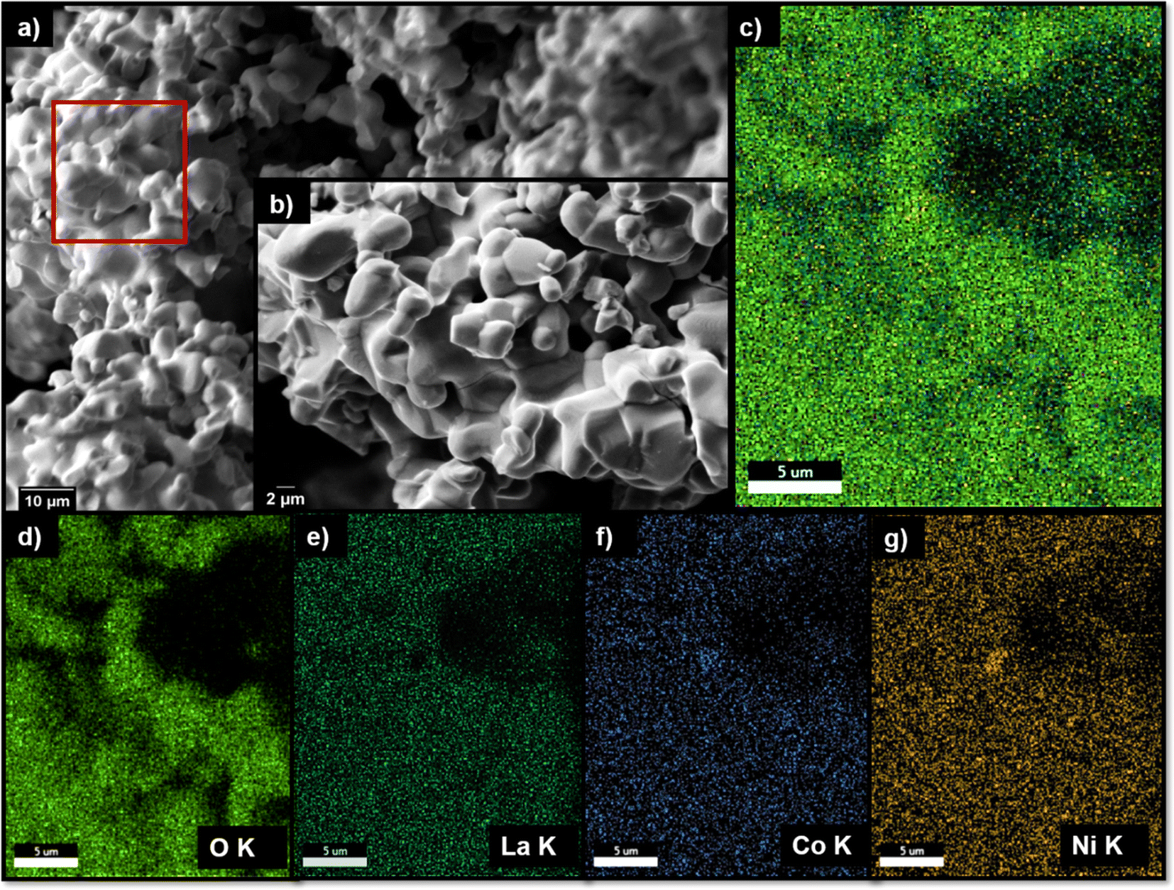 | ||
| Fig. 3 SEM micrograph of La2Ni0.75Co0.25O4.08 at (a) low magnification (800×), (b) higher magnification (6000×), elemental mapping of a specific area (red marked) (c) overlapped elements and (d–g) individual elements. | ||
In order to be used as the cathode in the all-solid-state FIB, the as-synthesized La2Ni0.75Co0.25O4.08 was ball-milled together with the electronically conductive carbon matrix along with ionically conductive La0.9Ba0.1F2.9 solid electrolyte. This serves not only to mix all the components together to form an intimate interfacial contact but also to reduce the particle size of the active material and to increase the electrochemically active surface area of the active material for the redox reactions. For the successful operation of the fabricated all-solid-state FIB, elevated operation temperatures of around 170 °C are necessary in order to achieve sufficient fluoride ion conductivity of the La0.9Ba0.1F2.9 solid electrolyte, which is reported to be in the order of 10−4 S cm−1.17 The temperature stability of the cathode composite mixture was also investigated by heating it at 170 °C for 100 h, i.e., conditions similar to the operating conditions of the FIB. From the comparison of the lattice parameters obtained from the Rietveld fits of the X-ray diffractograms of the as-synthesized parent oxide, ball-milled cathode, composite and heat-treated cathode composite, it is confirmed that ball milling and heating the composite do not influence the nature of the cathode active material and that any structural changes induced are strictly from the electrochemical reaction (see Fig. 2b and Table S1 of the ESI†). Further, the weight fractions of La2Ni0.75Co0.25O4.08 and the solid electrolyte within the cathode composite determined from Rietveld analysis of the XRD data match well with the expected values.
To test the electrochemical performance of La2Ni0.75Co0.25O4.08 as a cathode in FIBs, galvanostatic charging and discharging curves were recorded in an all-solid-state battery comprising La2Ni0.75Co0.25O4.08 II La0.9Ba0.1F2.9 II Pb–PbF2 within the modified stainless-steel Swagelok-type cell at 170 °C as shown in Fig. 1. First, the structural changes induced upon F− intercalation were determined. For this, separate cells were galvanostatically charged to different capacities up to 600 mA h g−1 (which is far beyond the theoretical capacity of the active cathode material and can thus help to indicate potential and capacity ranges in which side reactions of the carbon-based additive can occur) and analyzed by ex situ X-ray diffraction measurements of the cathode side of the pellet (see Fig. 4). Overall, the charging curve can be divided into three different zones as indicated in Fig. 4a.
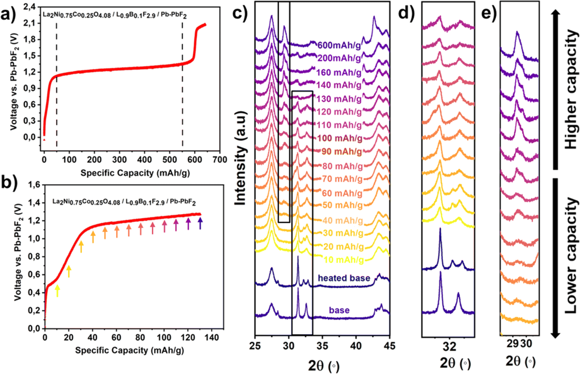 | ||
| Fig. 4 (a) Typical charging curve for the La2Ni0.75Co0.25O4.08/La0.9Ba0.1F2.9/Pb–PbF2 cell. (b) Below shows the details of the lower capacity range and the coloured arrows mark the chosen cut-off capacities for the charging process where the ex situ XRD measurements were taken, (c) ex situ diffraction pattern obtained from the individual cells charged at the different cut-off capacities, (d) enlarged view of the peak at 32° and (e) enlarged view of the peak at 29.5°. Full refinement of the single pattern with partial fit curves for different phases is shown in the ESI.† | ||
(1) A sharp increase in the voltage from 0.2 V to 0.45 V vs. Pb/PbF2 is observed. Such a sharp increase corresponds well with the initiation of the electrochemical reaction involving different processes like F− ion transport from the anode towards the cathode, i.e., the mass transport along with the accumulation of the charge at the electrolyte/cathode interface. In this region, the capacity contribution taken up is very low (∼2 mA h g−1).
The potential change from 0.45 to 0.55 V proceeds over a capacity range of 20–30 mA h g−1. This corresponds to the first oxidation of the transition metal-ions of the RP-type compound from fluoride-ion incorporation. The process only induces moderate changes of the lattice parameters (see later in this section), and is accompanied by broadening and asymmetry of the reflections (in particular those with l ≠ 0, e.g., shoulders appearing on the (103) reflection), see Fig. 4d. This likely originates from the lattice distortions occurring on inserting F− in the interstitial anion sites,25 and inhomogeneous F−distribution in the active material particles.
(2) Two processes likely occur simultaneously in the long plateau at ∼1.2–1.3 V, which are the fluorination of the carbon black additive in addition to the formation of a high fluorine content RP-type phase with a lattice parameter c around 15.275(3) Å, which has also been found for related materials37,38 and is indicated by an additional reflection at 29° within the X-ray diffractograms (Fig. 4e). As the charging process within this plateau proceeds, the reflection at 29° increases in intensity along with the decrease in the intensity of the indicative reflections of the parent (-related) compound La2Ni0.75Co0.25O4.08 at ∼31.5° and ∼32.5° respectively. At the end of this plateau, a full transformation of the RP-type phase to the phase with large lattice parameter c can be observed, and the reflections belonging to this phase become sharper again, indicating that defect-related strain broadening is reduced from the increased fluorination. We would like to emphasize here that pure carbon does only show a very short plateau at 1.2 V (see Fig. S12†); the active RP-type material has a redox-catalytic activity for oxidatively fluorinating the carbon, as described previously by Nowroozi.24,25
(3) Another potential increase beyond a specific capacity of 600 mA h g−1 cannot be assigned to further reaction of the RP-type phase, and likely corresponds to further degradation/oxidation of the carbon matrix,23–25,37,39,40 see also Fig. S12.†
Rietveld analysis can be used to analyze the details of the structural changes occurring on charging RP-type phases in FIBs. From this analysis, weight fractions as well as lattice parameters of the individual phases can be extracted. The results of this analysis (performed on the patterns shown in Fig. 5) can provide a more detailed understanding of the charging process. From a close inspection of the shape of the reflections of the RP-type phases, it becomes clear that it is not possible to refine the pattern of the low-fluorine content phases with a single RP-type phase, and multiple RP-type phases were found to be required to obtain an acceptable fit of the diffraction pattern (see Fig. S2†). On increased charging, we find changes in the different modifications of RP-type phases present along with changes in their phase fractions (see Fig. 6a). Partly, the lattice parameters and cell volumes of the individual phases can be slightly affected depending on the detailed state of charge.
 | ||
| Fig. 5 Scheme of structural changes in La2Ni0.75Co0.25O4.08 – the schematic illustrates the non-fluorinated La2Ni0.75Co0.25O4.08 (left) and the fluorinated phase along with two other different phases (right). | ||
 | ||
| Fig. 6 (a) Relative weight fractions (RWFs) of the phases formed. (b) Volume changes of different phases formed on charging up to various cut-off capacities. (c) Lattice parameters of different phases formed on charging up to various cut-off capacities. | ||
After heating, the sample is mainly composed of an orthorhombic phase (see Section 3.1), which we assign the label orthorhombic #1 in the following discussion. Orthorhombic distortions within RP-type material can have different origins: pure La2NiO4 is known to crystallize in the orthorhombic space group Pmnb, where the distortion originates from tilting of the octahedra within the a/b-plane, which mainly changes the coordination around the La-ions. In addition, orthorhombic distortions can also occur when filling of the interstitial sites takes place, e.g., as observed for La2NiO3F2 with space group Cccm, in which case the orthorhombic distortion is caused by the additional space required by the fluoride ions within the interlayers and accompanied by a moderate increase of the lattice parameter c (see Fig. 6c). Both, tilting occurring on either the increased ordering of anions or on small degrees of anion exchange reactions according to the following reaction equation, are possible and the individual effects cannot be separated precisely:
| A2BO4 + 2xF− → A2BO4−xF2x |
Upon charging beyond 10 mA h g−1 in the first region, the orthorhombic #1 phase fraction is found to decrease significantly. In addition, a tetragonal phase, as well as another orthorhombic phase (labeled as orthorhombic #2) appears. The tetragonal phase possesses cell parameters which appear to be fairly independent of the state of charge, in contrast to what is found for the orthorhombic #1 and #2 phases. The orthorhombic #2 and the tetragonal phase show an increase in the c-axis; in addition, the orthorhombic #2 phase shows an increase in the splitting of the a/b-lattice parameters at an overall increased cell volume as compared to the original state after heating. These changes remind us about the structural distortions found for orthorhombic La2NiO3F2,41,42 and we interpret this structural behavior as being induced by the fluoride-ions accumulating within the interstitial layers at a low content and inducing an orthorhombic distortion to be accommodated therein. The maximum overall amount of the orthorhombic phases is found between 30 and 40 mA h g−1, for which these phases amount to approximately 50% of the total RP-type phases. Considering that carbon side reactions mainly occur above 1.2 V and not in this potential range, one can estimate that the orthorhombic phases contain a maximum of 1 F per formula unit, further supported by the absence of a large increase of the c-axis, i.e. possess a maximum composition of La2Ni0.75Co0.25O4.08F1.
Upon further charging to a higher cut-off capacity, i.e. up to 160 mA h g−1, an additional phase can be observed in the X-ray diffractograms (Fig. 4e) with an indicative reflection at 29°. Schematic illustrations of fluorinated and non-fluorinated La2Ni0.75Co0.25O4.08 state have been shown in Fig. 5. From the Rietveld refinements, it was found that this phase can be refined within a monoclinic RP-type phase (the crystal system is indicated from the splitting of the reflections), for which we took the structural model with symmetry C2/c as previously observed for La2NiO4F1.7 from electron diffraction.30 The relative weight fraction (Fig. 6a) of this phase was found to increase with increased charging between 40 mA h g−1 to 160 mA h g−1. As can be seen from Fig. 6b, this monoclinic phase has an increased volume per La2Ni0.75Co0.25O4.08 unit by about ∼28 Å3 compared to the tetragonal, orthorhombic #1 and orthorhombic #2 phases. This volume change is indicative of a highly fluorinated phase with all interstitial sites occupied by fluoride ions17,24–26,41,43 and mainly originates from the large increase of the c-axis length to ∼15.275(3) Å, whereas the a/b parameters contract due to shortened (Co/Ni)–O bonds from the oxidation process (Fig. 6c). The chemical formula for this phase is likely close to La2Ni0.75Co0.25O4.08F1.92−δ (see also XAS analysis reported in Section 3.3). We note that on charging, a change of the relative weight fraction of the monoclinic phase occurs, whereas its unit cell volume remains mainly constant (Fig. 6b). This can be interpreted in the sense that this phase is saturated with fluoride ions already once it starts to occur, and might have a narrow compositional flexibility. The structural changes on fluorination are also in accordance with what has been observed for the chemical fluorination of Sr2TiO3F2 (c = 15.89 Å) and La2CoO4+dFy (c = 15.1930(6)) and electrochemical fluorinations of La2CoO4Fy (c = 15.292(1) Å), La2NiO4.13Fy (c = 15.255(30) Å), and LaSrMnO4F2−x (c = 15.631(7) Å).10,23–25,41
In order to understand the electrochemical defluorination behavior of the parent RP-type phases, the parent oxide was first charged to 130 mA h g−1 followed by discharging to different discharge capacities (20, 40, 60, 130 and 180 mA h g−1), shown in Fig. 7a and subsequent ex situ XRD analysis (see Fig. 7b). For the sample discharged to 20 mA h g−1, it is found that the monoclinic phase is still the major phase present along with the relatively lower weight fractions of the tetragonal, orthorhombic #1 and orthorhombic #2 phases. The major indicative reflection of the monoclinic phase at 29° is still visible for the discharged state of 20 mA h g−1 (see Fig. 7b), and no significant changes are observed for the lattice parameters. Upon discharging to 40 mA h g−1, the indicative reflection of the monoclinic phase is no longer visible and only the tetragonal and two orthorhombic modifications are found. For high coulombic efficiency (an absence of side reactions on charging), the discharge capacity of 40 mA h g−1 would correspond to the charging capacity of 90 mA h g−1. Interestingly, there is a clear difference between the relative weight fractions of the different phases at this stage shown in Fig. 8a. For charging to 90 mA h g−1, the main phase was found to be the monoclinic phase along with relatively lower weight fractions of the other phases; however, for reaching a comparable state on discharging, the monoclinic phase is completely absent. This also suggests the possible overlapping of side reactions along with the charging of the parent RP oxide phase. Such side reactions can be attributed to carbon fluorination which is well known in FIBs.24,26,37,44,45
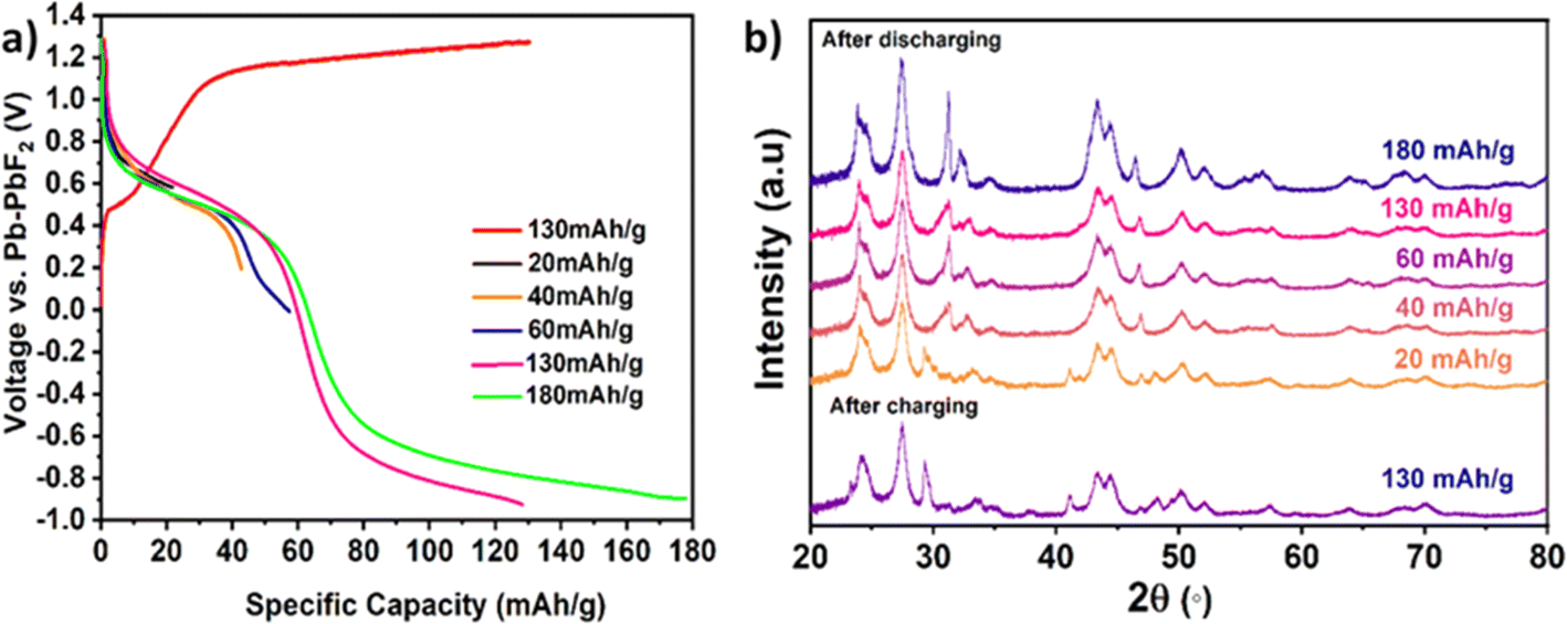 | ||
| Fig. 7 (a) Discharge curves for cells charged to a capacity of 130 mA h g−1 and discharged up to various cut-off capacities. (b) Diffraction patterns for the individual cells discharged to different discharge capacities. | ||
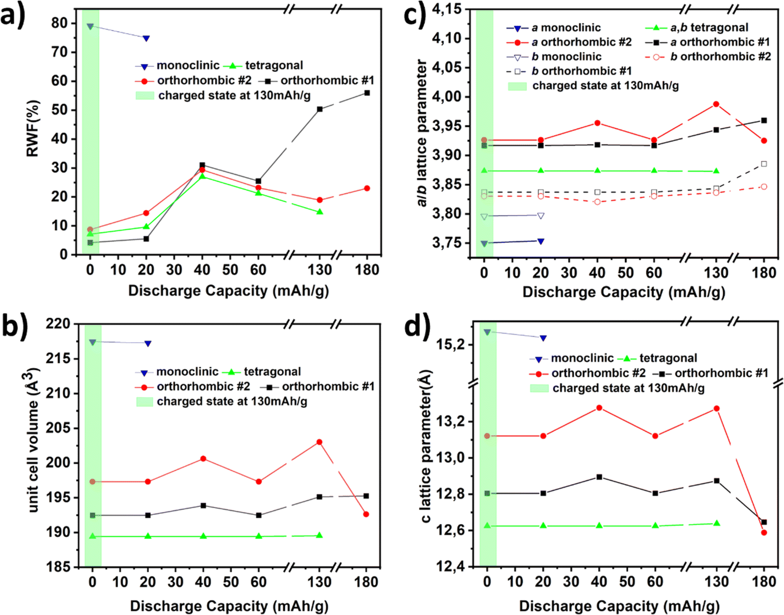 | ||
| Fig. 8 (a) RWFs of the phases formed (b) volume changes (c) lattice constants a, b and (d) lattice constant c of different phases formed on discharging up to various cut-off capacities. | ||
Compared to charged cells, the discharged cells show similar lattice characteristics for the orthorhombic phase #1 (a ∼ 3.9287 Å, b ∼ 3.8463 Å, c ∼ 12.8049 Å), orthorhombic phase #2 (a ∼ 3.9411 Å, b ∼ 3.8322 Å, c ∼ 13.0832 Å) and tetragonal phase (a ∼ 3.8733 Å, b ∼ 3.8733 Å, c ∼ 12.6272 Å) as seen in Fig. 8. Discharging to high discharge capacities (130/180 mA h g−1), i.e., inducing a larger reduction on discharging than oxidation on the prior charging, resulted in negative potentials against Pb/PbF2, with a decrease of the lattice parameters a, b and a decrease in lattice parameter c, resulting in a lower unit cell volume for both the orthorhombic phases. The lattice parameters of the discharged phases are similar to that of the charged phase without a strong indication of amorphisation from the refined weight fractions, hence confirming structurally reversible fluorination/defluorination under maintenance of the principle structural arrangement.
3.2 Cycling stability of La2Ni0.75Co0.25O4.08 as the cathode in FIBs
For its application in the FIBs as a potential cathode material, an attempt was made to determine the cycling stability of the parent RP phase. To do so, we examined cell reversibility on charging and discharging the cell to cutoff conditions of either 40 mA h g−1 or potentials of 1.3 V and 0 V against Pb/PbF2 on charging/discharging respectively. The capacity conditions were chosen according to the findings reported in Section 3.1, which show an increased amount of side reactions, if charging proceeds above 40 mA h g−1. As seen from Fig. 9, it is observed that the discharge capacity increases within the first 6 cycles after charging to the cutoff capacity of 40 mA h g−1. This enhanced discharge capacity as a function of cycle number can be related to reduced side reactions of the carbon additives on increased cycling.46,47 Thus, an increase in cycle number leads to higher active material utilization i.e. intercalation of F− within the RP phase as opposed to the side reactions, thus leading to higher discharge capacities. In previous studies, La2NiO4 was cycled at the cut-off capacity of 30 mA h g−1, whereas La2Ni0.75Co0.25O4.08 has shown certain stability at the increased cut-off capacity of 40 mA h g−1 and shows the cycling stability up to 120 cycles. Already after the first cycle (see Fig. 9a), the charging plateau shifted from lower potential to high potential by about 0.3 V and the specific capacity increased by ∼11%. After the second cycle, the charging plateau shifted again by ∼+0.2 V together with a further increase of the specific capacity of 32%. These voltage gaps are in agreement with the low coulombic efficiencies within the first cycles originating from the presence of side reactions such as decomposition of the carbon matrix, as discussed before. After this, the curves only show minor changes regarding their general shape up to 120 cycles (apart from a continuous increase of discharge capacity by 0.2–0.3 mA h per g per cycle, see Fig. S3,† resulting in improved coulombic efficiency). The discharge capacity remains highly stable with the coulombic efficiency of around 90% without significant capacity fading for 120 cycles as shown in Fig. 9b. La2NiO4 reported previously was found to show higher coulombic efficiencies between 95 and 99%.24 The lower coulombic efficiency of La2Ni0.75Co0.25O4.08 of up to 90% is thus likely related to consumptive processes at low cycles, and Co seems to be the most plausible origin for introducing the side reactions in the carbon additive. However, the capacity retention is also superior in comparison to pure La2CoO4.23 In contrast to this, Co can also have beneficial influences on the cycling behavior. This was observed when cycling the material close to the theoretical cut-off capacity of 130 mA h g−1. | ||
| Fig. 9 Cycling curves of La2Ni0.75Co0.25O4.08/Pb–PbF2 at T = 170 °C, Icharge = +8.0294 μA, Idischarge = −4.0145 μA, at the charging capacities (a) 40 mA h g−1 and (c) 130 mA h g−1 ,(b) charge/discharge capacities and coulombic efficiency against cycle number for the cells with the cut-off capacities of 40 mA h g−1 and (d) cycling curves of La2NiO4.13 under the charging condition of 120 mA h g−1. Reproduced with permission.1 Copyright 2023, Commun. Mater., 2020, 1. | ||
Under these conditions, a discharge capacity as high as 80 mA h g−1 could be observed after the 5th cycle, which is increased compared to pure La2NiO4 under such conditions (compare Fig. 9c to d).
The structural changes of the RP-type compounds at higher cycle numbers were examined within the first 21 charge–discharge cycles for the cut-off capacity of 40 mA h g−1 by stopping at the discharged state as shown in Fig. 10. Ex situ XRD measurements were done on the cathode composition and Fig. 10 shows the RWFs of the phases present in the cycled cells. The XRD patterns of the RP-type phases can be well fitted with the tetragonal phase and two orthorhombic phases. Compared to charged and discharged states, the cells cycled for 21 cycles show similar values of lattice parameters than the discharged state for orthorhombic phase #1 (a ∼ 3.9550 Å, b ∼ 3.8290 Å, c ∼ 12.988(4) Å). For orthorhombic phase #2, a lattice parameter seems to increase slightly and the lattice parameters b and c stay similar. For the tetragonal phase, the most significant change is observed in the 21st cycle, at which it seems to have a higher c lattice parameter together with an increased cell volume. These findings indicate that the reduced coulombic efficiency could also be partly related to changes in the structure and composition in the discharged state. This could be possibly explained by a redistribution of fluoride and oxide ions within the different fractions of RP-type phases formed on cycling. For example, if one phase enriches in oxygen and the other in fluorine, the oxygen-rich phase would not be accessible for further fluoride extraction to the same extent.
 | ||
| Fig. 10 (a) RWFs of the phases present in the cells operated for different cycle numbers and stopped in the discharge state, (b) volume changes and (c) lattice constants of different phases formed on charging–discharging of the cell at different number of cycles. | ||
3.3 Influence of charging/discharging on the electronic states and local structure of Ni and Co ions
Diffraction measurements, though important to characterize the overall structural changes on charging and discharging, are unsuitable to discriminate the individual behavior of the transition metals in multi-metal compounds. Thus, element specific X-ray absorption spectra were recorded to determine changes in the oxidation states as well as individual structural changes around the Ni and Co cations. First, we note that the mixing of the RP-type compound together with carbon and La0.9Ba0.1F2.9 has no influence on the position of the edges, and only the charging influences the position of the Ni and Co edges significantly, see Fig. S4.† However, clear changes in the absorption edges could be determined for the cells charged/discharged to different cut-off capacities. The Ni edge (see Fig. 11a) behaves similarly to what has been observed for pure La2NiO4+δ.24 On charging, the Ni edge shifts progressively to higher energies on increased fluoride uptake of the cathode side. The same trend was also observed for the pre edges of Ni shown in Fig. S5.† The pre-edge is more sensitive to the oxidation state, whereas the main edge has strong contribution from the bond lengths and the type of coordinating anions. The similar behavior of both the absorption energies gives strong confirmation that the Ni oxidation state does change and not just the structure around the atoms. Overall, a change of the oxidation state close to tetravalent Ni4+ is indicated when charging the cell to the highest state of charge.48 This is also in agreement with the changes of the bond distances around the Ni cation (see Table 1), which can be derived from the EXAFS region of the spectra (see Fig. 11b); here, we would like to emphasize that the errors of the bond distances are high and these values should only be interpreted as a general trend. The apical bond distances increase by about 25 pm, whereas the equatorial bonds contract by about 5 pm; the equatorial trend is well supported by the refinement of lattice parameters, which mainly influence them. On discharging the compound to negative potentials, this process seems to be well reversible. The edge position of Ni shifts back close to the original position of the sample before charging, and the bond distances are similar to the sample before charging (see Fig. 11c, d and Table 1). However, we note that the apical anion only moves back to the original position at high discharge capacities.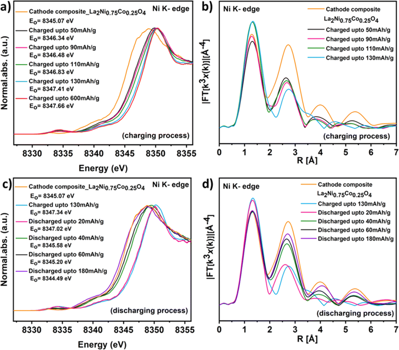 | ||
| Fig. 11 HERFD-XAS at the Ni K-edge (a) XANES of La2Ni0.75Co0.25O4.08 after F− insertion, (b) EXAFS of La2Ni0.75Co0.25O4.08 after F− insertion, (c) XANES of La2Ni0.75Co0.25O4.08 after F− extraction and (d) EXAFS of La2Ni0.75Co0.25O4.08 after F− extraction. | ||
| Sample | Ni–O eq. bond (pm) | Ni–O ap. bond (pm) |
|---|---|---|
| Cathode composite | 194 | 227 |
| Charged up to 50 mA h g−1 | 190 | 248 |
| Charged up to 90 mA h g−1 | 188 | 254 |
| Charged up to 110 mA h g−1 | 188 | 245 |
| Charged up to 130 mA h g−1 | 188 | 250 |
| Discharged up to 20 mA h g−1 | 188 | 246 |
| Discharged up to 40 mA h g−1 | 193 | 249 |
| Discharged up to 60 mA h g−1 | 194 | 238 |
| Discharged up to 180 mA h g−1 | 194 | 228 |
For Co, interesting differences are indicated as a tendency as compared to the Ni cation. On charging, the behavior of Co is in line with the behavior of Ni, the edges shift to higher energies in agreement with the oxidation of the Co cation (see Fig. 12 and S5†), the equatorial bond distances contract by about 5 pm and the apical distance increases by about 25 pm. However, on discharging by 60 mA h g−1, only the equatorial site expands to a bond distance close to what has been observed for the original sample, and the apical bond distances remain high at around 260 pm (see Table 2). The edge position becomes similar to before charging but indicates a slightly higher oxidation state than in the original sample. We hypothesize that this could be interpreted by the formation of Co3+ in an intermediate eg4b2g1a1g1 (for d-orbital splitting in D4h symmetry) spin state, which can be well stabilized in a more square-planar-related coordination. The large distance of the apical site indicates that the coordination around the Co-cation is more similar to a T′ RP-type structure as observed for Nd2CuO4 with oxide ions occupying the equatorial and interstitial anion sites. On discharging the sample further to 180 mA h g−1, the edge of Co shifts to a value which is 1.2 eV lower than the sample before charging. This change of oxidation state is additionally accompanied by an increase of the equatorial anion distance to 196 pm (again in conceptual agreement with increased lattice parameters a/b derived from diffraction analysis) and the apical bond distance reduces to 230 pm length. This indicates that oxidation states around or even lower than +2 might be possible on electrochemical reduction, which has been observed in chemical reduction of perovskite-related cobaltates before.49,50
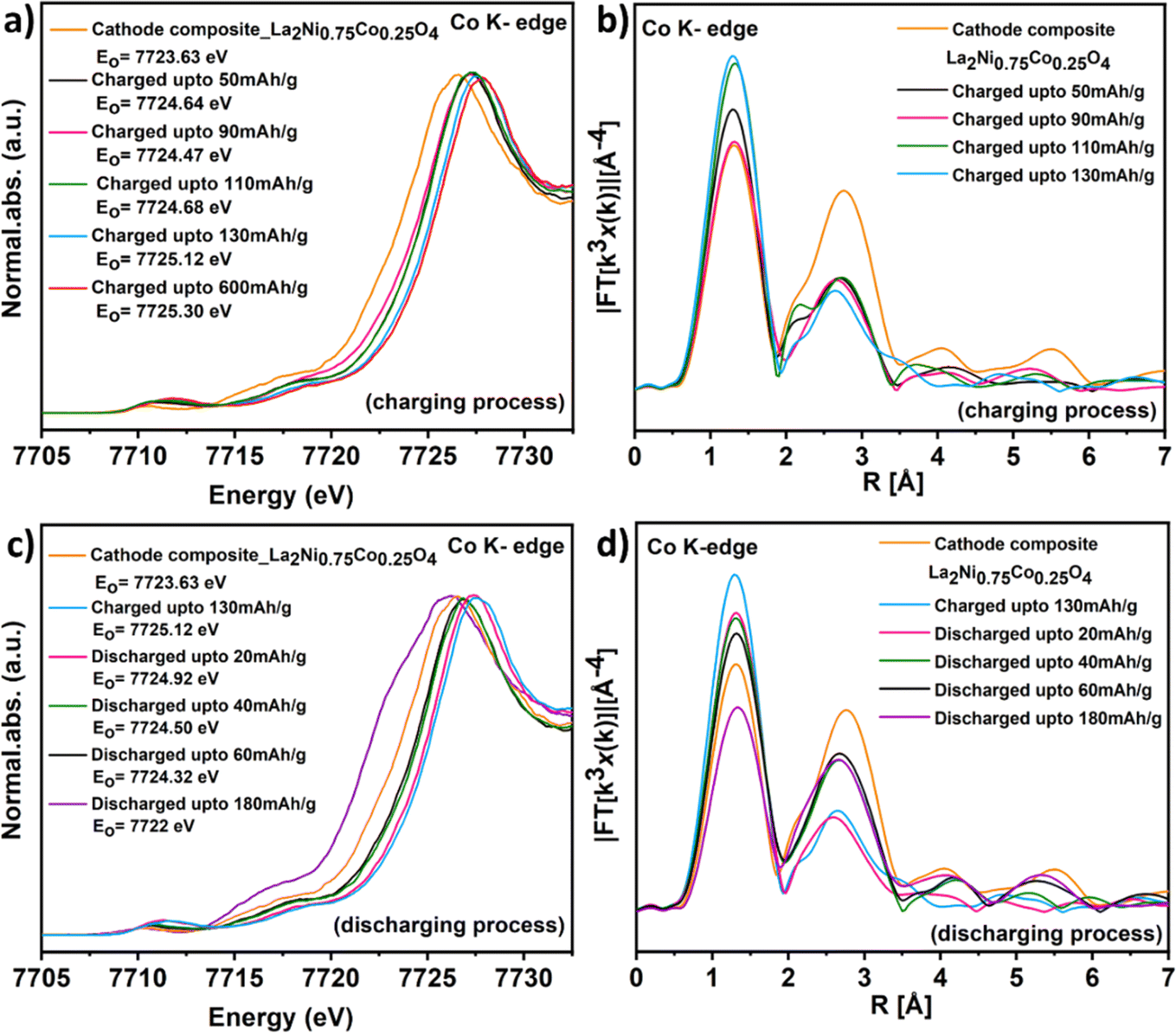 | ||
| Fig. 12 HERFD-XAS at the Co K-edge (a) XANES of La2Ni0.75Co0.25O4.08 after F− insertion, (b) EXAFS of La2Ni0.75Co0.25O4.08 after F− insertion, (c) XANES of La2Ni0.75Co0.25O4.08 after F− extraction and (d) EXAFS of La2Ni0.75Co0.25O4.08 after F− extraction. | ||
| Sample | Co–O eq. bond (pm) | Co–O ap. bond (pm) |
|---|---|---|
| Cathode composite | 191 | 219 |
| Charged up to 50 mA h g−1 | 189 | 215 |
| Charged up to 90 mA h g−1 | 191 | 247 |
| Charged up to 110 mA h g−1 | 189 | 236 |
| Charged up to 130 mA h g−1 | 186 | 251 |
| Discharged up to 20 mA h g−1 | 188 | 250 |
| Discharged up to 40 mA h g−1 | 189 | 259 |
| Discharged up to 60 mA h g−1 | 190 | 261 |
| Discharged up to 180 mA h g−1 | 196 | 231 |
Thus, the XAS analysis reveals that doping of La2NiO4 with Co induces a complex structural fluorination chemistry and that the fluorine incorporation, though occurring at decent coulombic efficiency might induce differences in the local surroundings of the different transition metal cations, which have an impact on the electrochemical properties.
3.4 Influence of charging/discharging on magnetic properties of La2Ni0.75Co0.25O4.08
To further characterize the La2Ni0.75Co0.25O4.08 compound, magnetic measurements were performed on the pristine, cathode composite, charged/discharged cells and cycled cells as shown in Fig. 13. | ||
| Fig. 13 Magnetization as a function of temperature and external magnetic field measured in (a) pristine La2Ni0.75Co0.25O4.08, (b) cathode composite of La2Ni0.75Co0.25O4.08 and different charging and (c) cycled state of La2Ni0.75Co0.25O4.08. | ||
The magnetic susceptibility of pure La2NiO4+δ, due to the flexibility of oxygen content δ, has been studied in a vast amount of literature with different results.51–53. Stoichiometric La2NiO4 is an orthorhombic (Bmab), brown, semiconducting, and antiferromagnetically ordered material below room temperature. Furthermore, it also transforms to a tetragonal modification with space group I4/mmm at temperatures above 700 K and shows an orthorhombic-to-orthorhombic transition at low temperatures, i.e. below 80 K.54
In contrast, oxidized La2NiO4+δ (0 < δ < 0.25) is a black material, which lacks 3D long-range order at any temperature below 300 K.54 Finally, with La2NiO4.25i.e. La8Ni4O17 clear oxygen ordering was observed with Fmmm at room temperature, but still no magnetic Bragg peaks were observed extending up to δ = 0.34.55
La2CoO4.25 was shown to order antiferromagnetically at 36 K with both oxygen and charge ordering via neutron diffraction.56 In contrast, La2CoO4 undergoes a Néel-type order at 275 K and a structural transition at 135 K to the tetragonal phase.57 For the substituted La2Ni0.75Co0.25O4.08 composite, no sharp transitions in susceptibility were expected due to the observations on the two parent compounds. As shown by the red curve in Fig. 13a, the susceptibility versus temperature in an applied field of 1 T shows a broad maximum in the susceptibility around 200 K, with the onset of an increase around 250 K. Since La2Ni0.75Co0.25O4.08 (black curve) already has an increased oxygen content no clear magnetic transition is expected and the origin of this maximum originates from the exchange interaction in low dimensional quantum magnets as this typical 2D Heisenberg magnet. The base sample for the reaction is a mixture of the La2Ni0.75Co0.25O4.08 composite with La0.9Ba0.1F2.9, which shows in the entire temperature range a paramagnetic contribution due to the nonmagnetic sample signal mixed with the sample holder (see Fig. 13a). The charged samples also contain diamagnetic graphene nanoparticles leading to a largely changed signal shown in Fig. 13a, where no maximum is apparent. Thus, for the measurements, it was tried to extract solely the La2Ni0.75Co0.25O4.08Fy part from the pellet. Hence, we plot the effective susceptibility in emu/Oe g−1 and note that the precise mass ratios of each sample might vary slightly, due to the different amounts of contamination with the base mixture as described earlier by Vasala et al.58
For the M(H) curves, a subtle hysteresis dominated by a Brillouin function with a very low moment of 0.002 μB for the pure La2Ni0.75Co0.25O4.08 was observed (not shown). Given the impossibility of dividing by the real molar masses due to a mixture in the fluorinated compounds, the M(H) curves in detail were not analysed but found in all a similar shape and coercivity.
In Fig. 13b, the effect of fluorination on the susceptibility of the cells charged at 50, 110 and 600 mA h g−1 is shown. This electrochemical fluorination of La2Ni0.75Co0.25O4.08 leads to changes in the susceptibility, without the appearance of long-range order (similar to increasing oxygen intercalation from 0.08 < δ < 0.34). It was found that with increasing charge the maximum shifts towards higher temperatures (highlighted by an arrow). This effect is in principle in agreement with what has been observed for oxygen intercalation, which effectively happens when increasing delta in La2NiO4+δ as we are separating the layers producing more 2D physics. Likely the Ni–O–Ni buckling decreases, which increases in-plane Js. For the maximum charge saturation is reached and instead disorder increased producing a less pronounced maximum. Finally, in Fig. 13c, the effect of cycling on the susceptibility is shown. No major effect on the susceptibility was observed besides a subtly varying signal strength due to the described varying contents of phases from repeated cycling. Notably however upon discharging or defluorination, we do not recover the susceptibility of pure La2Ni0.75Co0.25O4.08 likely due to a larger amount of disorder, which is also in agreement with the observations made in powder diffraction as well as the evaluation of XAS data.
4 Conclusions
In this study, we have demonstrated the first multi-transition element containing Ruddlesden–Popper-type La2Ni0.75Co0.25O4.08 as a cathode material for all-solid-state FIBs. Increasing the elemental complexity at the octahedrally coordinated transition metal site has changed the electrochemical behaviour of the material and makes it different from the parent compounds: La2CoO4 and La2NiO4. Detailed structural analysis via XRD has shown the successful insertion and removal of fluoride ions from the vacant anion rock salt interlayers of La2Ni0.75Co0.25O4.08, confirming the reversible fluorination/defluorination under maintenance of the lattice. XAS measurements have clearly shown the change in the oxidation state of Ni and Co upon electrochemical fluorination and the coordination environment around the transition metals such as contraction of the octahedron. Thus, the doping of La2NiO4 with cobalt has induced more complex structural fluorination chemistry with differences in the local surroundings, impacting the electrochemical properties. Regarding the interactions with the carbon matrix, Co also seems to be a strong player for introducing side reactions, though it also leads to more stable cycling closer to the maximum theoretical capacity compared to pure nickelates.At the moment, the full capacity of ∼140 mA h g−1 of RP-type materials has not been accessed in extended cycling experiments. Also, mixed cation compositions do not change this in a drastic manner, since the carbon additives appear to be too unstable. However, by minimizing the interactions with the carbon matrix independently (e.g., by choosing different geometries or different chemical approaches for the additives), mixed cation compounds might indeed help to obtain improved properties for a cathode material. Further, the anode chemistries would also have to be optimized in a similar way,30 to obtain high voltage batteries with properties more similar to current LIB systems.1
Author contributions
V. V.: writing the manuscript, executing the synthesis of the precursors, preparation of electrochemical cells and samples for further characterization measurements such as diffraction experiments, SEM-EDAX, electrochemical characterization, XAS measurement, magnetic measurements, and analysis of XRD, XAS and GCPL data including plotting of all the data. A. I. W.: guided the synthesis part in order to get a phase pure compound. P. P.: performed the magnetic measurements, plotted and analyzed the data. S. V. and R. S.: performed X-ray absorption spectroscopy with guidance from P. G. and M. B. S. V.: analyzed EXAFS data using X-ray Larch software. O. C.: designed the study and supervised the project. All authors read the final version of the manuscript and contributed to it by writing, corrections and/or suggestions.Conflicts of interest
The authors declare no conflicts of interest.Acknowledgements
This work was funded by the German Research Foundation within the Emmy Noether program (Grant CL 551/2-1). AMICA, Uni Stuttgart is acknowledged for providing access to the SEM device.References
- J.-K. Park, Principles and Applications of Lithium Secondary Batteries, John Wiley & Sons, 2012 Search PubMed.
- M. Akhilash, P. S. Salini, K. Jalaja, B. John and T. D. Mercy, Synthesis of Li1.5Ni0.25Mn0.75O2.5 cathode material via carbonate co-precipitation method and its electrochemical properties, Inorg. Chem. Commun., 2021, 126, 108434 CrossRef CAS.
- M. Akhilash, P. S. Salini, B. John and T. D. Mercy, A journey through layered cathode materials for lithium ion cells - From lithium cobalt oxide to lithium-rich transition metal oxides, J. Alloys Compd., 2021, 869, 159239 CrossRef CAS.
- S. Chen, T. He, Y. Su, Y. Lu, L. Bao, L. Chen, Q. Zhang, J. Wang, R. Chen and F. Wu, Ni-Rich LiNi0.8Co0.1Mn0.1O2 Oxide Coated by Dual-Conductive Layers as High Performance Cathode Material for Lithium-Ion Batteries, ACS Appl. Mater. Interfaces, 2017, 9(35), 29732–29743 CrossRef CAS PubMed.
- J. Liu and A. Manthiram, Understanding the Improved Electrochemical Performances of Fe-Substituted 5 V Spinel Cathode LiMn1.5Ni0.5O4, J. Phys. Chem. C, 2009, 113(33), 15073–15079 CrossRef CAS.
- X. He, S. Su, B. Zhang, Z. Xiao, Z. Zhang and X. Ou, Alleviating the anisotropic microstructural change and boosting the lithium ions diffusion by grain orientation regulation for Ni-rich cathode materials, J. Energy Chem., 2024, 88, 213–222 CrossRef CAS.
- List of Mineral Species, https://www.mindat.org/min-1576.html Search PubMed.
- F. Gschwind, H. Euchner and G. Rodriguez-Garcia, Chloride Ion Battery Review: Theoretical Calculations, State of the Art, Safety, Toxicity, and an Outlook towards Future Developments, Eur. J. Inorg. Chem., 2017, 2017(21), 2784–2799 CrossRef CAS.
- M. Anji Reddy and M. Fichtner, Batteries based on fluoride shuttle, J. Mater. Chem., 2011, 21(43), 17059–17062 RSC.
- K. Wissel, S. Dasgupta, A. Benes, R. Schoch, M. Bauer, R. Witte, A. D. Fortes, E. Erdem, J. Rohrer and O. Clemens, Developing intercalation based anode materials for fluoride-ion batteries: topochemical reduction of Sr2TiO3F2via a hydride based defluorination process, J. Mater. Chem. A, 2018, 6(44), 22013–22026 RSC.
- F. Gschwind, Z. Zao-Karger and M. Fichtner, A fluoride-doped PEG matrix as an electrolyte for anion transportation in a room-temperature fluoride ion battery, J. Mater. Chem. A, 2014, 2(5), 1214–1218 RSC.
- Y. Yu, M. Lei, D. Li and C. Li, Near-Room-Temperature Quasi-Solid-State F-Ion Batteries with High Conversion Reversibility Based on Layered Structured Electrolyte, Adv. Energy Mater., 2023, 13(12), 2203168 CrossRef CAS.
- Y. Yu, M. Lei and C. Li, Room-temperature reversible F-ion batteries based on sulfone electrolytes with a mild anion acceptor additive, Mater. Horiz., 2024, 11(2), 480–489 RSC.
- Y. Yu, A. Lin, M. Lei, C. Lai, C. Wu, Y.-Y. Sun and C. Li, High-Capacity and Long-Cycling F-Ion Pouch Cells Enabled by Green Electrolytes, ACS Energy Lett., 2024, 1008–1016 CrossRef CAS.
- K. Nakayama, R. Ishikawa, T. Tojigamori, H. Miki, H. Iba, N. Shibata and Y. Ikuhara, Fluoride-ion conversion alloy for fluoride-ion batteries, J. Mater. Chem. A, 2022, 10(7), 3743–3749 RSC.
- D. T. Thieu, M. Hammad, H. Bhatia, T. Diemant, V. S. K. Chakravadhanula, R. J. Behm, C. Kubel and M. Fichtner, CuF2 as Reversible Cathode for Fluoride Ion Batteries, Adv. Funct. Mater., 2017, 27(31), 1701051 CrossRef.
- M. A. Nowroozi, I. Mohammad, P. Molaiyan, K. Wissel, A. R. Munnangi and O. Clemens, Fluoride ion batteries - past, present, and future, J. Mater. Chem. A, 2021, 9(10), 5980–6012 RSC.
- L. Zhang, M. A. Reddy, P. Gao, T. Diemant, R. Jürgen Behm and M. Fichtner, Study of all solid-state rechargeable fluoride ion batteries based on thin-film electrolyte, J. Solid State Electrochem., 2017, 21, 1243–1251 CrossRef CAS.
- T. Yoshinari, D. T. Zhang, K. Yamamoto, Y. Kitaguchi, A. Ochi, K. Nakanishi, H. Miki, S. Nakanishi, H. Iba, T. Uchiyama, T. Watanabe, T. Matsunaga, K. Amezawa and Y. Uchimoto, Kinetic analysis and alloy designs for metal/metal fluorides toward high rate capability for all-solid-state fluoride-ion batteries, J. Mater. Chem. A, 2021, 9(11), 7018–7024 RSC.
- D. T. Zhang, K. Yamamoto, A. Ochi, Y. C. Wang, T. Yoshinari, K. Nakanishi, H. Nakano, H. Miki, S. Nakanishi, H. Iba, T. Uchiyama, T. Watanabe, K. Amezawa and Y. Uchimoto, Understanding the reaction mechanism and performances of 3d transition metal cathodes for all-solid-state fluoride ion batteries, J. Mater. Chem. A, 2021, 9(1), 406–412 RSC.
- J. Haruyama, K. I. Okazaki, Y. Morita, H. Nakamoto, E. Matsubara, T. Ikeshoji and M. Otani, Two-Phase Reaction Mechanism for Fluorination and Defluorination in Fluoride-Shuttle Batteries: A First-Principles Study, ACS Appl. Mater. Interfaces, 2020, 12(1), 428–435 CrossRef CAS PubMed.
- L. Zhang, M. A. Reddy and M. Fichtner, Development of tysonite-type fluoride conducting thin film electrolytes for fluoride ion batteries, Solid State Ionics, 2015, 272, 39–44 CrossRef CAS.
- M. A. Nowroozi, S. Ivlev, J. Rohrer and O. Clemens, La2CoO4: a new intercalation based cathode material for fluoride ion batteries with improved cycling stability, J. Mater. Chem. A, 2018, 6(11), 4658–4669 RSC.
- M. A. Nowroozi, K. Wissel, M. Donzelli, N. Hosseinpourkahvaz, S. Plana-Ruiz, U. Kolb, R. Schoch, M. Bauer, A. M. Malik, J. Rohrer, S. Ivlev, F. Kraus and O. Clemens, High cycle life all-solid-state fluoride ion battery with La2NiO4+d high voltage cathode, Commun. Mater., 2020, 1(1), 27 CrossRef.
- M. A. Nowroozi, K. Wissel, J. Rohrer, A. R. Munnangi and O. Clemens, LaSrMnO4: Reversible Electrochemical Intercalation of Fluoride Ions in the Context of Fluoride Ion Batteries, Chem. Mater., 2017, 29(8), 3441–3453 CrossRef CAS.
- K. Wissel, R. Schoch, T. Vogel, M. Donzelli, G. Matveeva, U. Kolb, M. Bauer, P. R. Slater and O. Clemens, Electrochemical Reduction and Oxidation of Ruddlesden-Popper-Type La2NiO3F2 within Fluoride-Ion Batteries, Chem. Mater., 2021, 33(2), 499–512 CrossRef CAS.
- O. Clemens, M. Kuhn and R. Haberkorn, Synthesis and characterization of the La1−xSrxFeO3−δ system and the fluorinated phases La1−xSrxFeO3−xFx, J. Solid State Chem., 2011, 184(11), 2870–2876 CrossRef CAS.
- E. E. McCabe and C. Greaves, Fluorine insertion reactions into pre-formed metal oxides, J. Fluorine Chem., 2007, 128(4), 448–458 CrossRef CAS.
- T. Sivakumar and J. B. Wiley, Topotactic route for new layered perovskite oxides containing fluorine: Ln1.2Sr1.8Mn2O7F2 (Ln=Pr, Nd, Sm, Eu, and Gd), Mater. Res. Bull., 2009, 44(1), 74–77 CrossRef CAS.
- M. A. Nowroozi, On the Development of Intercalation-Based Cathode Materials for All-Solid-State Fluoride Ion Batteries, TUprints:11523, 2020.
- Y. Wang, K. Yamamoto, Y. Tsujimoto, T. Matsunaga, D. Zhang, Z. Cao, K. Nakanishi, T. Uchiyama, T. Watanabe, T. Takami, H. Miki, H. Iba, K. Maeda, H. Kageyama and Y. Uchimoto, Anion Substitution at Apical Sites of Ruddlesden–Popper-type Cathodes toward High Power Density for All-Solid-State Fluoride-Ion Batteries, Chem. Mater., 2022, 34(2), 609–616 CrossRef CAS.
- K. Yamamoto, Development of Electrode Materials Based on Design Guideline of Electronic Structure Obtained by Synchrotron Radiation X-ray Analyses, Electrochemistry, 2023, 91(10), 102004 CrossRef CAS.
- Y. C. Wang, K. Yamamoto, Y. Tsujimoto, T. Matsunaga, D. T. Zhang, Z. L. Cao, K. Nakanishi, T. Uchiyama, T. Watanabe, T. Takami, H. Miki, H. Iba, K. Maeda, H. Kageyama and Y. Uchimoto, Anion Substitution at Apical Sites of Ruddlesden-Popper-type Cathodes toward High Power Density for All-Solid-State Fluoride-Ion Batteries, Chem. Mater., 2022, 34(2), 609–616 CrossRef CAS.
- J. B. Goodenough and K. S. Park, The Li-ion rechargeable battery: A Perspective, J. Am. Chem. Soc., 2013, 135(4), 1167–1176 CrossRef CAS.
- R. Bonne and J. Schoonman, The ionic conductivity of beta lead fluoride, J. Electrochem. Soc., 1977, 124(1), 28 CrossRef CAS.
- Larch: Data Analysis Tools for X-Ray Spectroscopy, https://xraypy.github.io/xraylarch/index.html Search PubMed.
- A. Grenier, A. G. Porras-Gutierrez, M. Body, C. Legein, F. Chretien, E. Raymundo-Pinero, M. Dolle, H. Groult and D. Dambournet, Solid Fluoride Electrolytes and Their Composite with Carbon: Issues and Challenges for Rechargeable Solid State Fluoride-Ion Batteries, J. Phys. Chem. C, 2017, 121(45), 24962–24970 CrossRef CAS.
- M. A. Nowroozi and O. Clemens, Insights on the Behavior of Conversion-Based Anode Materials for Fluoride Ion Batteries by Testing against an Intercalation-Based Reference Cathode, ACS Appl. Energy Mater., 2018, 1(11), 6626–6637 CrossRef CAS.
- M. A. Nowroozi, B. de Laune and O. Clemens, Reversible Electrochemical Intercalation and Deintercalation of Fluoride Ions into Host Lattices with Schafarzikite-Type Structure, ChemistryOpen, 2018, 7(8), 617–623 CrossRef CAS PubMed.
- N. J. Dudney, W. C. West and J. Nanda, Handbook of solid state batteries, World Scientific, 2015, vol. 6 Search PubMed.
- K. Wissel, Topochemical fluorination and defluorination in the context of fluoride-ion batteries and tuning of magnetic properties, TUprints:13383, 2020.
- K. Wissel, A. M. Malik, S. Vasala, S. Plana-Ruiz, U. Kolb, P. R. Slater, I. da Silva, L. Alff, J. Rohrer and O. Clemens, Topochemical reduction of La2NiO3F2: the first Ni-based Ruddlesden–Popper n= 1 T′-type structure and the impact of reduction on magnetic ordering, Chem. Mater., 2020, 32(7), 3160–3179 CrossRef CAS.
- K. Wissel, F. Bernardini, H. Oh, S. Vasala, R. Schoch, B. Blaschkowski, P. Glatzel, M. Bauer, O. Clemens and A. Cano, Single-Layer T'; Nickelates: Synthesis of the La and Pr Members and Electronic Properties across the Rare-Earth Series, Chem. Mater., 2022, 34(16), 7201–7209 CrossRef CAS.
- H. Touhara, J. Inahara, T. Mizuno, Y. Yokoyama, S. Okanao, K. Yanagiuch, I. Mukopadhyay, S. Kawasaki, F. Okino, H. Shirai, W. H. Xu, T. Kyotani and A. Tomita, Property control of new forms of carbon materials by fluorination, J. Fluorine Chem., 2002, 114(2), 181–188 CrossRef CAS.
- H. Touhara and F. Okino, Property control of carbon materials by fluorination, Carbon, 2000, 38(2), 241–267 CrossRef CAS.
- Z. Tu, P. Nath, Y. Lu, M. D. Tikekar and L. A. Archer, Nanostructured electrolytes for stable lithium electrodeposition in secondary batteries, Acc. Chem. Res., 2015, 48(11), 2947–2956 CrossRef CAS PubMed.
- Y. J. Zhang, W. Wang, H. Tang, W. Q. Bai, X. Ge, X. L. Wang, C. D. Gu and J. P. Tu, An ex-situ nitridation route to synthesize Li3N-modified Li anodes for lithium secondary batteries, J. Power Sources, 2015, 277, 304–311 CrossRef CAS.
- R. J. Woolley, B. N. Illy, M. P. Ryan and S. J. Skinner, In situ determination of the nickel oxidation state in La 2 NiO 4+ δ and La 4 Ni 3 O 10− δ using X-ray absorption near-edge structure, J. Mater. Chem., 2011, 21(46), 18592–18596 RSC.
- A. I. Waidha, L. Ni, J. Ali, M. Lepple, M. Donzelli, S. Dasgupta, S. Wollstadt, L. Alff, U. Kramm and O. Clemens, Synthesis of bifunctional BaFe 1− x Co x O 3− y− δ (OH) y catalysts for the oxygen reduction reaction and oxygen evolution reaction, J. Mater. Chem. A, 2020, 8(2), 616–625 RSC.
- A. I. Waidha, Developing nebulized spray pyrolysis as a synthesis route for energy materials: Composite electrolytes and mixed electron-proton-conductors, TUprints:20773, 2022.
- R. R. Schartman and J. M. Honig, Magnetic susceptibility investigations of the La2NiO4+δ system, Mater. Res. Bull., 1989, 24(6), 671–679 CrossRef CAS.
- D. J. Buttrey, J. M. Honig and C. N. R. Rao, Magnetic properties of quasi-two-dimensional La2NiO4, J. Solid State Chem., 1986, 64(3), 287–295 CrossRef CAS.
- N. J. Poirot, C. Allançon, P. Odier, P. Simon, J. M. Bassat and J. P. Loup, Magnetic Properties of La2NiO4.16and La2−xPrxNiO4+δ, J. Solid State Chem., 1998, 138(2), 260–266 CrossRef CAS.
- R. Sáez-Puche, F. Fernández, J. L. Martínez and J. Rodríguez-Carvajal, Neutron diffraction study on the orthorhombic form of La2NiO4, J. Less-Common Met., 1989, 149, 357–361 CrossRef.
- A. Aguadero, J. Alonso, M. Martínez-Lope, M. Fernandez-Diaz, M. Escudero and L. Daza, In situ high temperature neutron powder diffraction study of oxygen-rich La 2 NiO 4+ δ in air: correlation with the electrical behaviour, J. Mater. Chem., 2006, 16(33), 3402–3408 RSC.
- R. De Barros, M. Ceretti, W. Schmidt, V. Y. Pomjakushin and W. Paulus, Growth and Oxygen Stoichiometry Control of High-Quality La2CoO4+δ Single Crystals (δ = 0.25), Cryst. Growth Des., 2022, 22(9), 5542–5551 CrossRef CAS.
- K. Yamada, M. Matsuda, Y. Endoh, B. Keimer, R. J. Birgeneau, S. Onodera, J. Mizusaki, T. Matsuura and G. Shirane, Successive antiferromagnetic phase transitions in single-crystal La2CoO4, Phys. Rev. B: Condens. Matter Mater. Phys., 1989, 39(4), 2336–2343 CrossRef CAS PubMed.
- S. Vasala, A. Jakob, K. Wissel, A. I. Waidha, L. Alff and O. Clemens, Reversible Tuning of Magnetization in a Ferromagnetic Ruddlesden-Popper-Type Manganite by Electrochemical Fluoride-Ion Intercalation, Adv. Electron. Mater., 2020, 6(2), 1900974 CrossRef CAS.
Footnote |
| † Electronic supplementary information (ESI) available: Data supporting XRD, structural parameters, weight and atomic% from the EDAX analysis, XAS and EXAFS data, Fig. S1–S12 and Tables S1 and S2. See DOI: https://doi.org/10.1039/d4ta00704b |
| This journal is © The Royal Society of Chemistry 2024 |